Abstract
Incorporating continuous carbon fibre-reinforced polymer (CCFRP) parts within additive manufacturing processes presents a significant advancement in the fabrication of robust lightweight parts, particularly relevant to aerospace, engineering, and various industrial sectors. Nonetheless, prevailing additive manufacturing methodologies for CCFRP parts exhibit notable limitations. Techniques reliant on resin and extrusion entail extensive and costly post-processing procedures to eliminate support structures, constraining design versatility and complicating small-scale production endeavours. In contrast, laser sintering (LS) emerges as a promising avenue for industrial application. It facilitates the efficient and cost-effective manufacturing of resilient parts without needing support structures. However, the current state of research and technological capabilities has yet to yield an LS machine that integrates the benefits of continuous fibre reinforcement with the inherent advantages of the LS process. This paper describes the systematic development process according to VDI 2221 of a new type of LS machine with automated continuous fibre integration while keeping the advantages of the LS process. The resulting physical prototype of the machine is also presented. Furthermore, this study presents an approach to integrate the cost and Product Carbon Footprint of the process in the product design. For this purpose, a machine state model was developed, and the costs and Product Carbon footprint of a part were analysed based on the model. The promising potential for future lightweight products is demonstrated through the production of CCFRP parts.
1. Introduction
Employing continuous carbon fibre-reinforced polymer (CCFRP) parts in industrial settings holds considerable promise for economically and effectively reducing future product consumption and CO2 emissions [1]. CCFRP parts are distinguished by their high strength-to-weight ratio and superior mechanical tensile properties along the fibre direction. Continuous fibre integration bolsters the mechanical properties of fibre-reinforced components along the load path [2].
Additive manufacturing methods present a promising avenue for the tool-less and time-efficient fabrication of continuous carbon fibre-reinforced polymer (CCFRP) parts, allowing for a high level of customisation and intricate shapes. Material extrusion (MEX) techniques, including fused layer modelling (FLM) and ARBURG plastic free-forming (APF), have been extensively documented in the literature as practical approaches for additive manufacturing of CCFRP parts [3]. In MEX, a meltable polymer filament (FLM) or polymer granulate (APF) is melted through a heated nozzle and applied in layers to a build platform using kinematics. In current research and technology, three possible techniques exist for integrating continuous fibres into MEX. In [4,5], pre-impregnated continuous fibres are fixed to the part or build platform before the material is applied and then overprinted with the molten polymer. In [6,7,8,9], the polymer filament and the continuous fibre strand are fed separately via two nozzles onto the build platform or brought into contact/consolidated in a heated nozzle and then applied to the build platform. In [10,11,12], the continuous fibre strand is inside the polymer filament core before processing. Another category of processes for CCFRP parts is vat photopolymerisation (VPP). VPP is a resin-based process in which a photosensitive resin is cured or polymerised layer-by-layer using a light source (laser, projector) [13,14]. In VPP, according to the current state of research and technology, continuous fibres are manually placed on the build platform [13,15,16,17] or infiltrated into tube-like channels within the part and then cured using UV light [18]. However, CCFRP parts manufactured through MEX and VPP exhibit notable drawbacks attributed to their process-specific characteristics. These methods necessitate the use of support structures, which must be subsequently removed and disposed of post-production, incurring both time and cost. Moreover, the employment of support structures constrains the capacity to fabricate overhangs, cavities, and undercuts, consequently limiting part complexity. Additionally, the detachment of support structures may induce surface defects on the remaining part surfaces, leading to a less uniform appearance of the parts. Furthermore, MEX and VPP methodologies could be more conducive to cost-effective small-batch production.
By contrast, the laser-sintering (LS) process represents a promising alternative for producing CCFRP parts. The LS process is a powder bed-based process in which a primarily semi-crystalline thermoplastic is processed. In this process, the polymer powder inside the build chamber is first heated as uniformly as possible in the process window, i.e., between crystallisation temperature and just before the melting temperature, using infrared (IR) emitters placed directly above the build platform. A laser beam is used to apply the necessary energy required to melt the polymer particles selectively. Once the laser has completed the part layer, fresh powder is applied with a recoater and a set layer thickness. More detailed information on the structure of an LS machine and the process sequence can be found in [19]. In a comparative analysis of MEX, VPP, and LS regarding mechanical and thermal properties and long-term stability of polymer parts, LS emerges as particularly advantageous. LS enables the production of durable, functional parts with nearly isotropic mechanical properties [19,20]. Notably, LS offers the advantage of eliminating support structures, providing greater design flexibility. In LS, the unsintered powder is a supportive medium, streamlining the process without requiring time-consuming post-processing steps [19]. Furthermore, LS showcases its prowess by effortlessly crafting intricate parts with undercuts, cavities, and overhangs in a single step, achieving near-net-shape functionality with remarkable complexity. The LS process allows for efficient production of small batches by compactly positioning parts vertically and horizontally in the powder bed. Compared to FLM parts, LS parts have up to 19 times (tensile strength) and 14 times (elongation at break) less anisotropy, higher dimensional accuracy, and less surface roughness [14,19,20]. The LS process, thus, produces polymer parts with promising basic properties (matrix) for CCFRP parts.
However, no commercially available LS machines in the current state of technology allow a combination of the advantages of the LS process with the advantages of continuous fibres. Challenges for automated continuous fibre integration in the LS process are the movement of the coater required for each layer and the control of the part’s and powder bed’s surface temperatures. In the current state of research on additive manufacturing of CCFRP parts with the LS process, there is almost no research work addressing continuous fibre integration in the LS process. The research work identified is limited to technical boundary conditions (additional kinematics required for targeted fibre placement) [21] or to manual integration tests of rovings [22]. In [22], process-side interaction effects were identified when integrating coated rovings with 1000 single fibres (1K) made of carbon (Teijin Ltd., Tokyo, Japan), powder, and the recoater using a commercially available LS machine Sintratec Kit (Sintratec AG, Swiss, Brugg, Switzerland). In addition, the time of roving integration, i.e., before or after the coating of fresh powder, was investigated to determine the automatability of the process. A thermoplastic-compatible polymer dispersion PERICOAT AC 250 (Textilchemie Dr. Petry GmbH, Reutlingen, Germany) was used as a roving coating. Due to the lack of a machine concept, the potential for support structure-free production of complex lightweight products with continuous fibre reinforcement is limited. The process boundaries were analysed in [23], and the operating points of the process were identified in [24]. However, a systematically developed prototype LS machine with continuous fibre integration is still missing.
Besides the mentioned need for a systematic analysis of the part–machine interdependencies to raise the application potential of the process, an integration in a product development process with a focus on ecologic and economic characteristics is required. In [25], the importance of the early integration of production into the development process is identified. The developed parts are continuously evaluated regarding their economic and ecological impact during production [26]. Especially for currently unestablished processes, it is crucial to make the potential measurable at an early stage. For this purpose, evaluation models regarding economic and ecological impacts are required to enable a quantitative decision for a manufacturing process. The input data to the evaluation model should be the geometrical information of the parts. The required calculation should be based on material databases and measured values from the machines.
This paper presents the systematic development process of a prototypical LS machine with automated roving integration according to VDI 2221 [27], focusing on the definition of requirements with boundary conditions, the derivation of basic functions for automated roving integration, as well as concept development and selection using utility value analysis. The findings of [22] form the starting point for defining requirements and boundary conditions. To enable the evaluation of the process regarding cost and Product Carbon Footprint, a model for evaluating these parameters is presented. The goal is to present what a systematically developed LS machine with roving integration looks like and how the process can be evaluated during manufacturing process selection.
Section 2.1 describes the procedure for systematically developing an LS machine with automated roving integration following VDI 2221. The methodology for analysing the sustainability of parts manufactured by the developed LS machine is presented in Section 2.2. Afterwards, Section 3 presents the analysed machine concepts, as well as the final design of the machine. The functionality of the process is presented by the production of demonstrator parts, which are also evaluated regarding cost and Product Carbon Footprint. The paper ends with a summary and an outlook.
2. Materials and Methods
This section presents the procedure for systematic machine development based on VDI 2221. It describes the methodology for evaluating the developed LS machine regarding requirements and boundary conditions. Furthermore, it describes the process’s economic and ecological key figures.
2.1. Development of an LS machine with Continuous Fibre Integration following VDI 2221
Due to the manufacturer-specific control and machine architecture, commercially available LS machines do not have the option of functional expansion. Furthermore, some relevant process parameters cannot be changed, so an in-depth investigation of the influence and target variable relationships cannot be realised. A prototypical LS machine with automated roving integration is developed in this paper to enable automated roving integration in the LS process. The systematic development of an LS machine with automated roving integration is based on the VDI 2221 development methodology. The development steps presented in this paper can be seen in Figure 1.
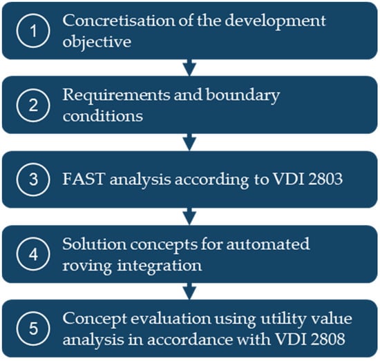
Figure 1.
Development steps for systematically developing an LS machine with continuous fibre integration according to VDI 2221.
In the first development step in Figure 1, the development objective is first concretised, and the scope of consideration is narrowed down. In the second development step, the requirements and boundary conditions for the LS machine to be developed are defined. The results from [22] form the starting point for defining requirements and boundary conditions. The basic functions required for automated roving integration are identified with the help of the function analysis system technique (FAST) following (VDI 2803) [28] in development step three. The fourth development step presents three solution concepts based on the basic functions, requirements, and boundary conditions for automated roving integration in the LS process. With the help of previously defined evaluation factors, the solution concepts are evaluated in development step five as part of a utility value analysis following VDI 2808. Based on the results of the utility value analysis, the most promising solution concept is selected. Finally, the developed LS machine with automated roving integration, which was developed based on the selected concept, is presented. A detailed derivation, analysis, and optimisation of the process-side influencing and target variable relationships (reduction in process times and increase in reproducibility and process reliability, improvement in the fibre–matrix bond, optimisation of the fibre volume content, and determination of the mechanical properties) will be omitted in this paper. These properties were presented in [23,24,29,30]. Determining the mechanical part properties achievable with the developed LS machine is also different from the subject of this paper (see [31]).
2.2. Production of Demonstrator Parts Using the Developed LS machine
To validate and evaluate the requirements and boundary conditions for the LS machine to be developed, the demonstrator parts shown in Figure 2 were manufactured with continuous roving reinforcement.
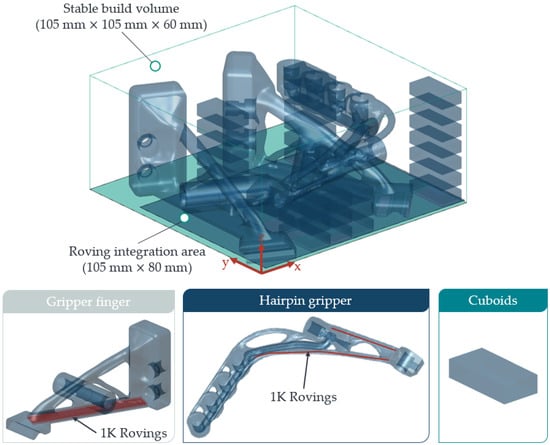
Figure 2.
Demonstrator parts for validation and evaluation of the LS process with automated continuous fibre integration.
The demonstrator parts are two gripper fingers with an integrated air channel for an additional suction gripper. Furthermore, it is a suction gripper with an integrated vacuum ejector (Venturi nozzle) for handling hairpins within the production lines of an electric motor assembly. The cuboids with dimensions of 30 mm × 15 mm × 6 mm are simple specimen geometries used for filling the powder bed. The in-house developed MATLAB R2020a-based app, LSFibrePLaner (LSFP), is used for laser control and deriving the NC code for automated roving integration [32]. Depending on the powder requirement calculated by the LSFP for the respective print, the mixing ratio between old and new powder can be determined. The material and process parameters used to manufacture the demonstrators are listed in Table 1 and are based on source.

Table 1.
Process and material parameters of the LS machine selected for the demonstrator parts.
2.3. Modelling of the Economic and Ecologic Impacts of the Process
Based on the procedure described in the previous chapter, the systematically developed machine for LS with roving integration is presented in Section 3. In order to be able to evaluate parts produced by the developed machine in the development of components, such as the gripper fingers shown in Figure 2, compared to other manufacturing processes, it is necessary to quantify the costs and CO2 emissions during production. It is important to provide this information in the early stages of product development, when the impact is greatest. The Life Cycle Assessment (LCA) is a known method for assessing the ecological impact of a product. The requirements for an LCA are defined in the DIN EN ISO 14040 [33] and the DIN EN ISO 14044 [34]. This paper calculates the PCF based on the guideline DIN EN ISO 14067 [35]. First of all, the goal of the analysis needs to be defined to calculate the PCF. In this case, the aim is to analyse the PCF and the cost of a part design during the development phase. The system boundaries of the PCF need to be defined concerning the goals [35]. This paper considers the cradle-to-gate life cycle. This includes the raw material production as well as the part manufacturing until it is leaving the prudcing company. This requires the process modelling to analyse the PCF and cost of the incoming material as well as the manufacturing energy and time.
To compare the energy consumption of LS process with other processes, it is best to use a machine state model [36]. For the analysed LS process with roving integration, the machine state model needs to be extended. The resulting machine state model is shown in Figure 3.
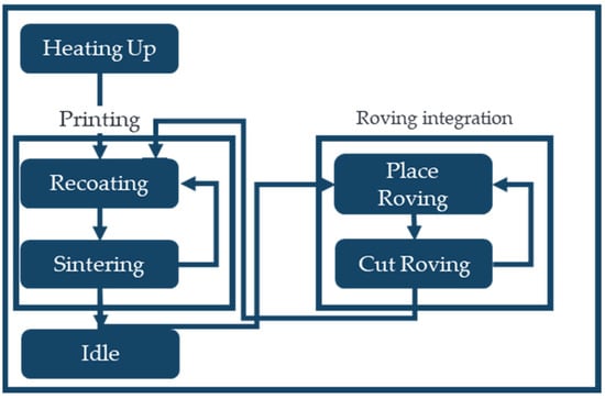
Figure 3.
Operation view as state diagram of the LS process with roving integration.
Compared to a conventional powder bed fusion process machine state model, as presented in [36], the state of fibre placement has been added on the right-hand side. The process starts on the left-hand side by heating up the machine’s assembly space. Afterwards, the printing process begins with the recoating of the layer and the sintering process. Suppose a fibre needs to be integrated. The machine switches to fibre integration and returns to the printing status after all fibres are integrated into the layer. During the fibre’s integration, the machine’s fibre integration unit must wait until the roving integration for the layer is finished. Different energy consumers need to be considered in each machine state.
The machine states are parametrised through power consumption measurements during production. The measurement setup is visualised in Figure 4.
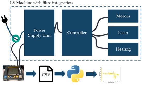
Figure 4.
Setup for power measurement of the machine.
The power consumption is measured with a clamp-on power analyser Yokogawa IM CW 240P-D (Yokogawa Electric Corporation, Tokyo, Japan). The measured data are stored in a CSV file analysed with Python (3.11). The clamp-on power analyser is mounted on the main cable of the machine, which measures the energy consumption of the entire system. Since the operation state of the machine is known during the measurements, the energy consumption can be assigned to the machine states based on the measurements.
To calculate the energy consumption resulting from the parametrised machine states, the time the machine is in each machine state needs to be estimated based on the product design. Niazi et al. [37] summarised and categorised existing approaches for estimating manufacturing costs. The focus of this paper is not just on costs but also on PCF, but the time estimation is for both. Therefore, the activity-based times are calculated using an analytical approach. The heating time for the assembly chamber only depends on the heating equipment used and the required temperature for the process. The printed part has no impact. Therefore, the heating time is set to 90 min based on experience knowledge.
One machine state is the conventional LS process. In [38], the time for the LS process is presented according to Equation (1):
The part volume and the part surface describe the part. These parameters are the results of the geometry of the printed part.
The layer thickness depends on the required surface roughness as well as on the machine boundaries. The number of lasers , the diameter of the laser , the hatching distance , and the scanning speed depend on the machine possibilities.
For each layer, a recoating step is required. The recoating time is machine-specific and is equal for each layer. However, it depends on the number of layers how often it is needed. The total amount of recoating time is calculated with Equation (2):
The height of the part in the printing direction depends on its geometry and orientation in the printer’s assembly space. In Figure 2, this is the z-direction.
The time for integrating the rovings in one layer can be calculated with Equation (3):
Equation (3) is based on the number of rovings and the length of the rovings . These variables define the length of all fibres in one layer and depend on the part design. Based on the physical relationships between velocity, time, and distance, the speed for roving integration is the machine-dependent parameter used for the time calculation. After placing the rovings, each roving needs to be separated, which is considered with an additional time , which is the time for cutting one roving.
The PCF for the system boundaries is calculated by Equation (4).
PCFCradle-to-gate = PCFMaterial extraction + PCFManufacturing
The PCF during the raw material extraction is calculated by Equation (5). is the density of the material, and are the CO2equ per kg of the material.
The PCF during manufacturing PCFManufacturing is calculated by Equation (6) and mainly depends on the energy consumption during manufacturing. The printing time is calculated by Equations (1) and (2). The called power of the machine depends on the current state of manufacturing, which is defined in Figure 2. The PCF of electricity depends on the country of the production and represents the CO2-emissions for one kwh. The presented machine and process is located in Karlsruhe, Germany.
Based on DIN EN ISO 14051 [39], manufacturing costs can be structured as shown in Figure 5. The machine in this study is used in a laboratory environment. Therefore, the costs of are reduced to the direct production costs and the material costs .
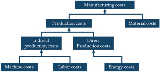
Figure 5.
Cost structure based on the DIN EN ISO 14051 [39].
With Equation (7), the Costdirect are calculated. CostEnergy are the costs per kwh electricity.
Based on the mentioned basics of machine modelling, the cost and PCF calculation, and the time estimation, a model that supports the evaluation of the parts is generated. The inventory data used for materials and electricity are summarised in Table 2. The power value is a live estimated value and, therefore, very volatile.

Table 2.
Parameters used for calculating the cost and PCF manufactured with LS with roving integration.
3. Results and Discussion
First of all, this section presents the results from the development steps shown in Figure 1 and the resulting LS machine. In addition, the manufactured parts are presented and discussed. Furthermore, the parametrisation of the machine state model is presented, and the evaluation of a manufactured part is demonstrated.
3.1. Development of an LS Machine with Automated Roving Integration
In Section 2.1, the individual development steps to develop the LS machine with automated roving integration are presented. This section presents the results of the development steps.
3.1.1. Concretisation of the Development Objective
The LS machine to be developed is intended to enable layer-related and load-path-compatible part reinforcement using continuous fibre strands (1K rovings) made of carbon. In other words, rovings will be automatically integrated into the part structure during the layer-by-layer build-up process within the LS process. Due to the existing explanations in the state of the art and research and technology on the development and construction of pure LS machines [47], a description of the development process of the complete LS machine is omitted in this paper. The development objective is therefore limited to deriving a fibre integration unit for the related layer, i.e., two-dimensional and automated integration of coated 1K rovings made of carbon within a prototypical LS machine.
3.1.2. Requirements and Boundary Conditions
An essential boundary condition is the continuous retention of the process window of the semi-crystalline thermoplastic used to avoid premature crystallisation of the part or overheating of the entire powder bed. Leaving the process window (overheating of the powder bed or part crystallisation) leads to process errors and, in the worst case, to process interruption or damage to machine components [19]. Furthermore, for automated roving integration, the repetitive movement of the recoater with fresh powder over the powder bed after completing a part layer must be considered for each part layer. According to [22], if rovings are not integrated deep enough into the part, the recoater may entrain the integrated rovings. This also results in a process interruption [24]. For reproducible and process-reliable roving integration, the roving strand must be integrated as far as possible below the movement plane of the recoater, i.e., within the part or the fresh powder layer (layer thickness), to avoid an entrainment effect. Another boundary condition in the LS process is the lack of bonding of the parts to a build platform. The parts lie loose, i.e., without a permanent fixation, in the powder bed. If excessive integration forces occur due to roving integration, this can lead to the displacement of the parts and thus to process errors or parts that are not dimensionally accurate. Furthermore, according to [22], for optimum load transfer from the matrix to the roving, the rovings must be connected to the part layers already produced (bottom side of rovings) and to the newly applied part layer (top side of roving). The boundary conditions for the fully automated LS machine to be developed for CCFRP parts considered in this paper are listed in Table 3.

Table 3.
Requirements and boundary conditions for the LS machine to be developed.
As can be seen in Table 3, the most widely used material in the LS process is PA12. PA12 has a large process window compared to other common polymers for the LS process [19]. 1K rovings are used as a coating with a thermoplastic-compatible polymer dispersion (PERICOAT AC 250, Textilchemie Dr. Petry GmbH, Reutlingen, Germany) in the current state of research. Compared to 3K or 6K rovings, 1K rovings have a significantly lower thickness, which is expected to result in more reliable roving integration into the part and below the movement plane of the recoater in the LS machine to be developed. By using the conventional LS process without any additional tools or support structures, the advantages of the LS process are kept. Process boundaries regarding the highest possible fibre volume content, the most homogeneous possible roving distribution within the part, and the lowest possible pore content of the manufactured CCFRP parts were described in [31]. The identification of the operating point to improve the reproducibility, process reliability, and process speed of the roving investigation was presented in [24]. This paper focuses on systematic machine development and the evaluation of sustainability. For this reason, the boundaries and process optimisation are not part of this paper.
3.1.3. FAST Analysis According to VDI 2803
To systematically derive the basic functions required for automated roving integration in the LS process, a FAST analysis following VDI 2803 is used with the help of a FAST diagram. With the FAST diagram, the scope for the product to be developed (fibre integration unit) is defined within a left and right system boundary. Outside the left system boundary, the main purpose or the function with the highest order is defined. In the horizontal viewing direction (from left to right), the sequential definition of functions required to solve the main purpose is carried out. To solve the main purpose (from left to right), a new lower-order function is created (how does a lower-order function solve the higher-order function?). In the opposite direction, i.e., from right to left, the higher-order function is justified by using lower-order functions (why is the higher-order function needed?). In the vertical direction, the temporal sequence of the identified functions is also categorised. Based on this function analysis, the functions will be systematically determined, and the process flow for integrating rovings will be concretised. Figure 6 shows the FAST diagram for the developed fibre integration unit.
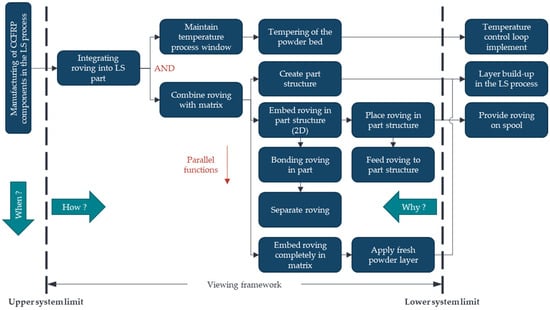
Figure 6.
FAST diagram for the continuous fibre integration to be developed.
The main purpose of the LS machine to be developed is the automated production of CCFRP parts. The rovings must be integrated into the parts to be reinforced following the derived FAST diagram and its basic functions to fulfil this purpose. Based on the requirements and boundary conditions from Section 3.1.2, Table 4 summarises the basic functions required for roving integration.

Table 4.
Overview and explanation of the basic functions for continuous fibre integration.
To integrate the rovings, the powder bed or part surface temperature must be continuously controlled within the process window (basic function 1) to protect the powder bed or part from crystallisation or overheating. Suppose the temperature falls below the crystallisation temperature or exceeds the melting temperature of the polymer used. This can be achieved by controlling the powder bed’s or part surface’s temperature using a temperature control loop. The roving and the matrix must be bonded to integrate rovings into the part structure previously produced by the LS process. For a bond to be formed, the matrix or the part structure to be reinforced must first be created by the LS process (basic function 2). This is followed by the layer-related, two-dimensional embedding of one or more rovings in the part structure in sequential order. For individual rovings to be embedded in the matrix, the initially continuous roving must be conveyed to the process zone (basic function 3) and positioned in the part structure (basic function 4). The roving must be bonded to the already generated part structure underneath the roving (basic function 5) to form the composite.
Another critical aspect of the LS process is bonding the rovings to other part layers in the build-up direction. This bonding is achieved by applying and melting fresh powder, ensuring the matrix surrounds the rovings. Before the rovings are fully embedded in the matrix, they must be separated using a separation mechanism dependent on the part size (basic function 6). Once the roving has been separated, fresh powder is applied to the powder bed surface and the parts with integrated rovings. The laser beam selectively melts the newly applied powder layer, thus completely embedding the roving in the matrix (basic function 7). The functions with the lowest order are thus the rolled-up and coated roving on a spool, the part structure generated by the LS process, and a control circuit for controlling the temperature of the part or powder bed surface temperature.
3.1.4. Solution Concepts for Roving Integration in the LS Process
Based on the basic functions identified in Table 4 for roving integration, this section presents three solution concepts and their evaluation using a utility value analysis.
Figure 7 shows the first concept, “pressure roller”, schematically.
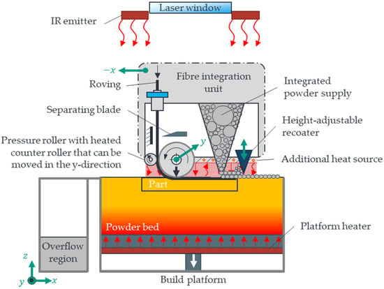
Figure 7.
Schematic representation of the pressure roller concept.
The initial state for the first concept is a part structure produced by the LS process within the powder bed tempered in the process window (basic function 1/2). The roving is conveyed to the process zone with the help of a pair of rollers, consisting of a heated counter roller and a pressure roller required for embedding (basic function 3). The roving is partially positioned by a synchronous sequence of movements between the conveying speed of the roving, which is generated by the pressure roller, and the resulting feed rate of the fibre integration unit during interpolation in the x and y directions (basic function 4). The roving is heated to a defined temperature with the help of the heated counter roller, which favours the formation of the bond during the pressing of the roving by the pressure roller (basic function 5). Before reaching the end position of a roving path, a separating blade is used to cut the roving to a part-dependent length (basic function 6). Due to the shading of the IR radiation by the structure of the fibre integration unit, the part and powder bed surface are continuously kept warm using an additional heat source on the bottom of the fibre integration unit (basic function 1). The laser installed in the LS machine is inactive for the entire duration of the roving integration. The recoater, part of the fibre integration unit, is initially offset in the z-direction and above the powder bed so that no powder is applied to the parts during the roving integration period. After integration of the last roving or all rovings have been integrated into the part layer according to the NC code, the recoater is set down to the required layer thickness, and fresh powder stored in the fibre integration unit is applied to the powder bed. After the fibre integration unit has been moved to the machine zero point, the laser melts the powder particles to embed the roving completely in the matrix (basic function 7). This process is repeated until all part layers have been produced. The controlled cooling process follows this and, finally, part removal. Table 5 lists the advantages and disadvantages of the “pressure roller” concept.

Table 5.
Advantages and disadvantages expected for the pressure roller concept.
Figure 8 shows a schematic representation of the second “downholder” concept.
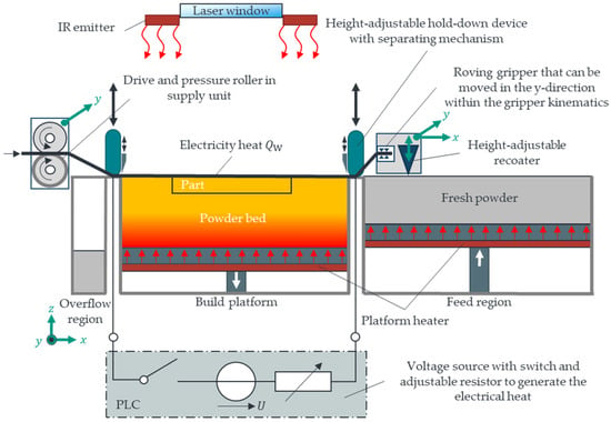
Figure 8.
Schematic representation of the “downholder” concept.
As in the first concept, the starting point for the "downholder" concept is a part structure produced by the LS process within a powder bed tempered in the process window (basic function 1/2). The roving is conveyed into the process chamber before embedding with the help of a supply unit (basic function 3). A clamping unit with an integrated, height-adjustable recoater and a gripper kinematic system that can be moved in the x and y directions is used to pick up the roving at the supply unit on the left-hand side of the build platform. The gripper kinematics move to the left end so that the roving gripper can receive the provided roving from the supply unit. The gripper kinematics then moves in the x and y directions with the picked-up roving, pulling it parallel to the x-axis or diagonally across the build platform (build function 4). The roving to be integrated is clamped over the powder bed surface, and the part is to be reinforced with the help of vertically movable downholders. The roving is pressed against electrical contacts by the lowered downholders, creating an electrical circuit. By applying a voltage and controlling an electrical resistance, the current flow through the electrically conductive roving causes the roving to heat (Joule heat). The heat generated by the roving causes the roving to bond to the part and the surrounding powder bed (basic function 5). After the bond is formed, the roving is separated at the left and right edges of the build platform, and the ends of the roving are pressed into the powder bed by the separating blade (basic function 6). Pressing the roving ends into the powder bed is intended to avoid possible interfering contours for the recoater. Once all rovings have been integrated, the recoater is lowered within the gripper kinematics to the set layer thickness of the part and fresh powder is applied to the powder bed containing the parts with rovings. Melting the applied powder layer with the laser results in the complete embedding and bonding of the rovings in the matrix (basic function 7). During the entire roving integration, the part with rovings and the powder bed is tempered in the process window of the polymer by the IR emitters installed in the LS machine. The subsequent layer-by-layer build-up process follows this. Table 6 lists the advantages and disadvantages of the "hold-down" concept.

Table 6.
Advantages and disadvantages expected for the downholder concept.
The “fibre nozzle” concept is shown schematically in Figure 9 and is based on [48].
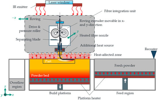
Figure 9.
Schematic representation of the fibre nozzle concept. Illustration based on [30].
As in the first two concepts, the starting point for the "fibre nozzle" concept is a part structure produced by the LS process within a powder bed tempered in the process window (basic function 1/2). The roving is conveyed through a heated fibre nozzle with a central bore within the process chamber at a defined conveying speed using a drive and pressure roller (basic function 3). The heated fibre nozzle is located above the part surface with a defined air gap distance. The viscosity of the molten part is reduced locally by heat transfer from the fibre nozzle to the part. A heat-affected zone (HAZ) is created within the part structure with a shape-defining width and depth. A synchronised movement sequence between the resulting feed rate of the fibre integration unit and the fibre nozzle in the x and y directions and the conveying speed of the roving ensures the targeted positioning and integration of the roving into the HAZ. The roving is increasingly heated as it moves through the heated fibre nozzle. The resulting intrinsic heat of the roving and, as a result, the inherent stiffness of the roving (basic function 4) causes the roving to bond to the matrix (basic function 5). Before reaching the end position of the roving path, the roving is cut to a part size-dependent length (basic function 6). During the entire duration of the roving integration, the powder bed and part surface temperature are kept warm within the process window of the polymer used with the help of an additional heat source on the bottom of the fibre integration unit (basic function 1). More information on heat transfer (heat transfer by free convection with internal flow) between the fibre nozzle, additional heat source, and powder bed surface can be found in [24,30]. The layer-by-layer build-up process is continued after all rovings have been integrated into the part layer according to an NC code. Table 7 lists the advantages and disadvantages of the “fibre nozzle” concept.

Table 7.
Advantages and disadvantages expected for the fibre nozzle concept.
3.1.5. Concept Evaluation and Selection Using Utility Value Analysis
The solution concepts presented in the previous section are evaluated in this section using a utility value analysis following VDI 2808 based on weighted evaluation criteria. Thus, the most promising solution concept for automated roving integration has been selected. In [48], the evaluation criteria with weighting were derived using a pairwise comparison. The highest weighted evaluation criteria (20%) are the process stability when coating the integrated roving with fresh powder and the ability of the solution concepts to maintain the process window during roving integration. The evaluation criteria with weighting and the result of the NWA carried out are shown in Table 8.

Table 8.
Summary of the results of the utility value analysis.
The first two concepts (pressure roller, downholder) were rated mediocre due to the high risk of powder adhesion to the pressure roller (concept 1) or in-build curling due to the current heat in concept 2. For the “fibre nozzle” concept, the process stability was rated very good, as powder adhesion can be avoided by an adjustable air gap distance between the fibre nozzle and the part surface. By implementing surface heating on the underside of the FI unit for the “fibre nozzle” concept, reliable maintenance of the process window is expected compared to the pressure roller concept. It should also be emphasised that a higher degree of freedom can be achieved for the “fibre nozzle” concept concerning roving path complexity. In addition to linear and angled roving paths, curved paths with a radius can also be realised, allowing for more targeted, load-path-compliant part reinforcement. Although the fibre nozzle concept is expected to be highly complex regarding mechanical design and cost, the advantages of process stability, maintaining the process window and roving path complexity, and the automation capability, which is rated as good, outweigh the disadvantages. According to Table 8, the “fibre nozzle” concept has the highest utility value with 740 points. The “fibre nozzle” concept is thus implemented in the prototype LS machine.
3.2. LS Machine with Automated Roving Integration
This section presents the developed LS machine with automated roving integration. A detailed description of the process sequence, as well as the systematic derivation, analysis, and optimisation of the process-side influencing and target variable relationships for process-stable and reproducible roving integration is omitted in this paper (please refer to [23,24,30,31]. Figure 10a shows the realised, prototypical LS machine.
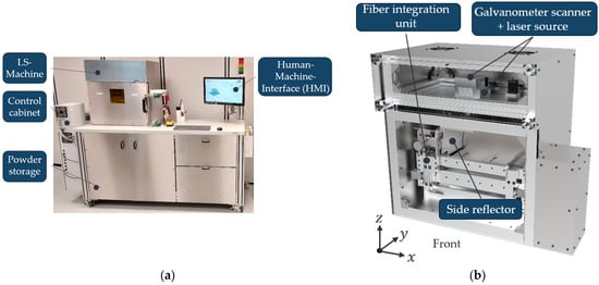
Figure 10.
Developed LS machine (a) and CAD model (without door) with a view into the process chamber (b). Illustration based on [30].
Figure 10b shows the CAD model of the LS machine (without a door) with a view into the process chamber. The core elements of the LS machine are a galvanometer scanner, a diode laser, a blade recoater, an F-theta lens, a powder storage container, and heat sources (IR emitters, platform heaters) with temperature control (pyrometer, PT100) so that parts can be generated layer by layer in the developed LS machine. The core elements installed in the developed LS machine (with the manufacturer) and the porosity of the parts to measure part quality (without the influence of roving integration) are listed in Table 9.

Table 9.
Components installed in the LS machine with description.
A fibre integration unit installed in the process chamber is used for the layer-related integration of rovings. The fibre integration unit within the process chamber of the LS machine is shown in Figure 11.
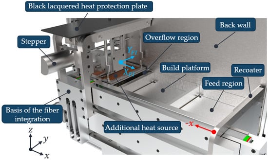
Figure 11.
Overall structure of the fibre integration unit within the process chamber of the developed LS machine. Illustration based on [30].
According to Figure 11, the fibre integration unit can be moved two-dimensionally along the and axes over the entire build platform. Figure 12 provides a more detailed illustration of the fibre integration unit and a description of the core elements.
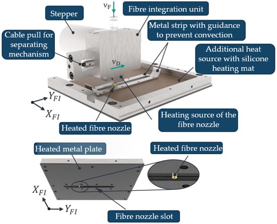
Figure 12.
Detailed illustration of the fibre integration unit with designation of the main components. Illustration based on [30].
As shown in Figure 12, the fibre integration unit consists of a roving extruder (stepper motor) with a drive roller to generate the roving feed in the direction of the part, a pressure roller to ensure slip-free roving feed, and a separating blade with a rope pull to cut through the rovings. Furthermore, an additional heat source on the bottom of the fibre integration unit is used to keep the part and powder bed surface warm within the process window. The additional heat source consists of a black-painted metal sheet and a bonded silicone heating mat with a PT100 temperature sensor (otom® Group GmbH, Bräunlingen, Germany). A heating cartridge heats the fibre nozzle.
3.3. Evaluation of Economic and Ecologic Impacts of the Process
This section presents the parametrisation of the machine state model as well as the application of the model to evaluate a part produced by the developed machine.
3.3.1. Determination of Power Consumption during Machine States
Based on the setup presented in Section 2.3, the machine’s power consumption was measured during the manufacturing of the parts presented in Section 2.2. In Figure 13, the measured power consumption is visualised over time.
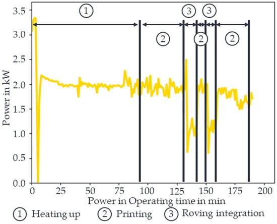
Figure 13.
Measured power consumption during the manufacturing of CCFRP parts.
The data are smoothed with piecewise aggregate approximation with a window size of 60. In state one, the machine is heating up. Initially, the machine was at room temperature, meaning the heater’s full power was initially called up. Afterwards, it falls to around 2 kW during this state. If the temperature for sintering is reached, the power of the heaters is reduced a little bit. In phase two, the LS process starts, which requires the laser and motors for positioning. During the roving integration in three, the power consumption is significantly reduced because the laser is switched off, and the heaters covered by the fibre integration unit are switched off. The peak at the beginning of the roving integration results from the fact that the pyrometer for measuring the temperature of the powder bed is covered by the cold fibre integration unit, which temporarily increases the heating power. The measured data calculate the average power consumption for each operation state. The results are summarised in Table 10.

Table 10.
Average power consumption during operation states.
The calculated average power consumption during the machine states forms the basis for the energy consumption calculations.
3.3.2. Evaluating Costs and PCF of the LS Process with Roving Integration
The presented process enables it to manufacture parts with different geometries. The printed demonstrator parts from Figure 2 are shown in Figure 14a.
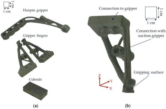
Figure 14.
Manufactured parts (a) and a detailed view of the evaluated gripper finger (b).
It is also possible to print them during one printing process. This leads to a reduction in the manufacturing time and the PCF of each part. The reason for this is that the heating time and the time for recoating can be divided between several parts. The evaluation of cost and PCF is demonstrated on the gripper finger with an integrated suction gripper function for handling parts in a training system in Figure 14b. The complex structure is possible only through the design freedom of additive manufactured parts. The main load case of the front strut is bending. Therefore, it was supported by roving integration. Since the machine can only insert rovings in the printing plane, the part must be aligned so that the printing direction is perpendicular to the strut. The input parameters of the part for evaluating costs and PCF are summarised in Table 11.

Table 11.
Relevant part parameters for calculating the costs and PCF.
All of the parameters are defined during the design process and can be extracted from the part’s CAD model. Thus, the evaluation can occur during product design and be integrated into the decision process. The Y-direction is selected as the printing direction, leading to a height in the printing direction of 41.5 mm.
Based on the part data, the time in each machine state is calculated using Equations (1)–(4). The calculation results are summarised in Table 12.

Table 12.
Calculated times in the operation states for the gripper finger.
Besides the heating-up time taken from Table 1, the times are part-specific and can be assigned to the part geometry. The heating-up time depends on the process temperature and not on the number of parts or the geometry of the parts. For this reason, the energy consumption during the heating phase is only charged proportionally to the part. The goal in manufacturing planning should be to use the space of the assembly as well as possible. The amount of energy used to heat up the part is the proportion of the part’s bounding box in the total construction chamber. The finger gripper takes 25% of the chamber. Therefore, just 25% of the energy consumption during heating up is assigned to the gripper finger. Furthermore, Table 12 presents the printing time for the gripper finger with the recoating time. If several parts are in the build chamber, the recoating is performed once for each layer and not for each part. Therefore, the power consumption during recoating is just assigned proportionally to the part. For this purpose, the area of the bounding box in the printing level is calculated. For the presented finger, it is the Bunding Box in the X and Z directions. This leads to a surface area of 3686 mm2. The area in the printing level is 11,025 mm2 according to Figure 2. The calculated times result in an overall energy consumption of 2.15 kWh. With Equations (6) and (7), the energy can be converted to the costs and PCF of the part. Figure 15 presents the ratio between material and energy costs during manufacturing as well as the PCF of the part.
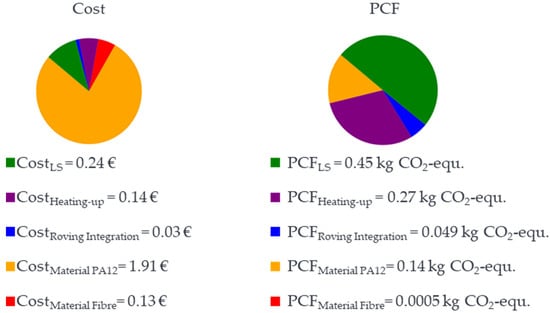
Figure 15.
Breakdown of costs (left) and PCF (right).
Furthermore, the ratio between PCF material and PCF manufacturing is visualised. The values of the material are split into the part of rovings and the part of the PA 12 powder. Furthermore, the energy costs and energy PCF of manufacturing are divided into the operation states of the machine. With the assumed frame, without considering the machine costs and labour costs, the total part costs EUR 2.45. A huge part of the costs are the material costs, followed by the energy costs during the printing process. The PCF in Figure 15 results in a total PCF of 0.91 kg CO2-equ.
The biggest part of the PCF is PCF resulting from the energy consumption during the LS process. The ratio between the PCF during manufacturing and the PCF of material also depends on the used power mix for the calculation. The PCF for this operation state will also increase with increasing fibre amount. The results give a hint regarding the main cost and PCF driver of products manufactured with the LS process with roving integration. Furthermore, the modelling of the process enables engineers to evaluate the products compared to other products with other manufacturing processes. A huge benefit is the material consumption of the process because, using LS’s potential, only the material used for the part needs to be considered in the evaluation. Furthermore, manufacturing several parts in one print job enables part-independent consumption to be divided between several parts. The manufacturing of lightweight parts also reduces costs and PCF during the use phase of the product. The cooling down time was neglected during the evaluation of the process. For a process selection, this should definitely be integrated.
4. Conclusions
With the LS machine concept derived in this paper, a layer-related integration of continuous fibre strands (1K rovings) into LS components is now possible and thus a combination of the advantages of the LS process with the advantages of continuous fibre reinforcement is possible without the disadvantageous properties of MEX and VPP (the use of support structures, lower part complexity, time-consuming and cost-intensive post-processing of parts for the removal and disposal of support structures in the case of MEX and VPP and for post-exposure in the case of VPP; limited part throughput and poorer dimensional accuracy and surface quality in the case of MEX; and high brittleness in the case of VPP). The core element of this prototypical LS machine is a fibre integration unit used for integrating the rovings into the already manufactured layers of the part. A heated fibre nozzle is used to liquefy the polymer locally, creating a heat-affected zone (HAZ) with a characteristic width and depth. The roving is then placed into the liquefied melt by a synchronised sequence of motions between the roving feed rate and the nozzle feed rate. For implementing the process in the industry and comparing the potential to other manufacturing processes from a cost and PCF point of view, the machine was described with different machine states. For each machine state, the power consumption was measured with a current clamp. Based on the average consumption for each machine state and analytical time models based on product design parameters, the process evaluation for manufacturing a specific part was demonstrated. The roving integrations lead to additional manufacturing time compared to the LS process. However, in the presented part, the impact of the roving on the PCF is very small. The increasing manufacturing time created through roving integration led to increased costs compared to parts produced by LS. The combination of the systematic development of an LS machine with roving integration and the developed model for sustainability evaluation supports the implementation of the novel manufacturing process in the industry.
Further research is needed to speed up the process and support the designer in finding the optimum between the amount of rovings and the PA 12 material. Furthermore, the LS machine developed can currently only process PA12. In order to expand the range of materials, further LS powder materials must be qualified, and process parameters for automated roving integration must be found. In addition, through-impregnated semi-finished fibre products such as those used in FDM are too stiff for the developed fibre integration unit and cannot be cut. Further development is necessary to utilise the better material properties of these semi-finished products. To improve the data quality of the consumption, more data during manufacturing are required. Furthermore, an assistance tool is required to analyse the potential of the products in the development process. Moreover, the impact of the part during the use phase needs to be integrated into the evaluation process.
Author Contributions
Conceptualization, M.B. and J.S.; methodology, M.B. and J.S; validation, M.B. and J.S.; writing—original draft preparation, M.B. and J.S; writing—review and editing, F.K. and J.F.; visualization, M.B. and J.S; supervision, J.F. All authors have read and agreed to the published version of the manuscript.
Funding
The authors thank the “Technologietransfer-Programm Leichtbau (TTP LB)” of the Federal Ministry for Economic Affairs and Climate Action (BMWK) and Projektträger Jülich (PTJ) for supporting their research within their project “SyProLei” (03LB2007G).
Data Availability Statement
Data are contained within the article.
Conflicts of Interest
The authors declare no conflicts of interest.
References
- Bundesministerium für Wirtschaft und Klimaschutz. Schlüsseltechnologie Leichtbau. Available online: https://www.bmwi.de/Redaktion/DE/Schlaglichter-der-Wirtschaftspolitik/2019/05/kapitel-1-6-schluesseltechnologie-leichtbau.html (accessed on 6 November 2023).
- Schürmann, H. Konstruieren mit Faser-Kunststoff-Verbunden, 2., Bearbeitete und Erweiterte Auflage; Springer: Berlin/Heidelberg, Germany, 2007; ISBN 9783540721895. [Google Scholar]
- Bakhtiari, H.; Aamir, M.; Tolouei-Rad, M. Effect of 3D Printing Parameters on the Fatigue Properties of Parts Manufactured by Fused Filament Fabrication: A Review. Appl. Sci. 2023, 13, 904. [Google Scholar] [CrossRef]
- Yao, X.; Luan, C.; Zhang, D.; Lan, L.; Fu, J. Evaluation of carbon fiber-embedded 3D printed structures for strengthening and structural-health monitoring. Mater. Des. 2017, 114, 424–432. [Google Scholar] [CrossRef]
- Nakagawa, Y.; Mori, K.-I.; Maeno, T. 3D printing of carbon fibre-reinforced plastic parts. Int. J. Adv. Manuf. Technol. 2017, 91, 2811–2817. [Google Scholar] [CrossRef]
- Matsuzaki, R.; Ueda, M.; Namiki, M.; Jeong, T.-K.; Asahara, H.; Horiguchi, K.; Nakamura, T.; Todoroki, A.; Hirano, Y. Three-dimensional printing of continuous-fiber composites by in-nozzle impregnation. Sci. Rep. 2016, 6, 23058. [Google Scholar] [CrossRef] [PubMed]
- Tian, X.; Liu, T.; Yang, C.; Wang, Q.; Li, D. Interface and performance of 3D printed continuous carbon fiber reinforced PLA composites. Compos. Part A Appl. Sci. Manuf. 2016, 88, 198–205. [Google Scholar] [CrossRef]
- Liu, S.; Li, Y.; Li, N. A novel free-hanging 3D printing method for continuous carbon fiber reinforced thermoplastic lattice truss core structures. Mater. Des. 2018, 137, 235–244. [Google Scholar] [CrossRef]
- Bettini, P.; Alitta, G.; Sala, G.; Di Landro, L. Fused deposition technique for continuous fiber reinforced thermoplastic. J. Mater. Eng. Perform. 2017, 26, 843–848. [Google Scholar] [CrossRef]
- Dickson, A.N.; Barry, J.N.; McDonnell, K.A.; Dowling, D.P. Fabrication of continuous carbon, glass and Kevlar fibre reinforced polymer composites using additive manufacturing. Addit. Manuf. 2017, 16, 146–152. [Google Scholar] [CrossRef]
- Goh, G.D.; Dikshit, V.; Nagalingam, A.P.; Goh, G.L.; Agarwala, S.; Sing, S.L.; Wei, J.; Yeong, W.Y. Characterization of mechanical properties and fracture mode of additively manufactured carbon fiber and glass fiber reinforced thermoplastics. Mater. Des. 2018, 137, 79–89. [Google Scholar] [CrossRef]
- van Der Klift, F.; Koga, Y.; Todoroki, A.; Ueda, M.; Hirano, Y.; Matsuzaki, R. 3D Printing of Continuous Carbon Fibre Reinforced Thermo-Plastic (CFRTP) Tensile Test Specimens. OJCM 2016, 06, 18–27. [Google Scholar] [CrossRef]
- Karalekas, D.E. Study of the mechanical properties of nonwoven fibre mat reinforced photopolymers used in rapid prototyping. Mater. Des. 2003, 24, 665–670. [Google Scholar] [CrossRef]
- Gebhardt, A. Additive Fertigungsverfahren: Additive Manufacturing und 3D-Drucken für Prototyping—Tooling—Produktion, 5., neu Bearbeitete und Erweiterte Auflage; Hanser: München, Germany, 2016; ISBN 978-3-446-44401-0. [Google Scholar]
- Greer, C.; McLaurin, J.; Ogale, A.A. Processing of Carbon Fiber Reinforced Composites by Three Dimensional Photolithography; University of Texas at Austin: Austin, TX, USA, 1996. [Google Scholar]
- Lu, Y.; Han, X.; Gleadall, A.; Chen, F.; Zhu, W.; Zhao, L. Continuous fibre reinforced Vat photopolymerisation (CONFIB-VAT). Addit. Manuf. 2022, 60, 103233. [Google Scholar] [CrossRef]
- Boyala, G.; Dehgahi, S.; Zubair, M.; Ullah, A.; Waghmare, P.; Qureshi, A.J. 3D printed human hair—polymer continuous fiber reinforced composites through Vat Photopolymerization process. Mater. Today Commun. 2023, 35, 106096. [Google Scholar] [CrossRef]
- Crescenti, M. New Post-Process for Reinforcing 3D Printed Parts Using Continuous Carbon Fibers. Available online: https://reinforce3d.com/#technology (accessed on 6 November 2023).
- Schmid, M. Lasersintern (LS) mit Kunststoffen: Technologie, Prozesse und Werkstoffe, 2., Aktualisierte und Erweiterte Auflage; Hanser: München, Germany, 2023; ISBN 9783446466647. [Google Scholar]
- Wegner, A.; Witt, G. Adjustment of isotropic part properties in laser sintering based on adapted double laser exposure strategies. Opt. Laser Technol. 2019, 109, 381–388. [Google Scholar] [CrossRef]
- Goh, G.D.; Yap, Y.L.; Agarwala, S.; Yeong, W.Y. Recent Progress in Additive Manufacturing of Fiber Reinforced Polymer Composite. Adv. Mater. Technol. 2019, 4, 1800271. [Google Scholar] [CrossRef]
- Moll, P.; Pirrung, F.; Baranowski, M.; Coutandin, S.; Fleischer, J. Evaluation of Fibre Placement Strategies for the Implementation of Continuous Reinforcement Fibres in Selective Laser Sintering Process. In Proceedings of the SAMPE Conference 2020, Online, 1 June 2020. [Google Scholar]
- Baranowski, M.; Völger, L.; Friedmann, M.; Fleischer, J. Experimental Analysis and Optimisation of a Novel Laser-Sintering Process for Additive Manufacturing of Continuous Carbon Fibre-Reinforced Polymer Parts. Appl. Sci. 2023, 13, 5351. [Google Scholar] [CrossRef]
- Baranowski, M.; Shao, Z.; Spintzyk, A.; Kößler, F.; Fleischer, J. Simulation-Based Identification of Operating Point Range for a Novel Laser-Sintering Machine for Additive Manufacturing of Continuous Carbon-Fibre-Reinforced Polymer Parts. Polymers 2023, 15, 3975. [Google Scholar] [CrossRef] [PubMed]
- Scholz, J.; Kaspar, J.; Quirin, S.; Kneidl, B.; Kleiner, S.; Friedmann, M.; Fleischer, J.; Herrmann, H.-G.; Vielhaber, M. Konzept eines systemischen Entwicklungsprozesses zur Hebung von Leichtbaupotenzialen. Z. Wirtsch. Fabr. 2021, 116, 797–800. [Google Scholar] [CrossRef]
- Kaspar, J.; König, K.; Scholz, J.; Quirin, S.; Kleiner, S.; Fleischer, J.; Herrmann, H.-G.; Vielhaber, M. SyProLei-A systematic product development process to exploit lightweight potentials while considering costs and CO2 emissions. Procedia CIRP 2022, 109, 520–525. [Google Scholar] [CrossRef]
- Verein Deutscher Ingenieure. Entwicklung Technischer Produkte und Systeme—Gestaltung Individueller Produktentwicklungsprozesse; Beuth: Berlin, Germany, 2019; VDI 2221; Available online: https://www.dinmedia.de/de/technische-regel/vdi-2221-blatt-2/311603776 (accessed on 4 November 2023).
- Verein Deutscher Ingenieure. Funktionenanalyse—Grundlagen und Methode; Beuth: Berlin, Germany, 2023; VDI 2803; Available online: https://www.beuth.de/de/technische-regel/vdi-2803-blatt-1/296563038 (accessed on 4 November 2023).
- Baranowski, M.; Beichter, S.; Griener, M.; Coutandin, S.; Fleischer, J. Additive manufacturing of continuous fibre-reinforced plastic components by a novel laser-sintering process. In Proceedings of the SAMPE Europe Conference 2021, Online, 30 June–1 July 2021. [Google Scholar]
- Baranowski, M.; Basalla, F.; Kößler, F.; Fleischer, J. Investigation of the Thermal Characteristics of a Novel Laser Sintering Machine for Additive Manufacturing of Continuous Carbon Fibre-Reinforced Polymer Parts. Polymers 2023, 15, 3406. [Google Scholar] [CrossRef] [PubMed]
- Baranowski, M.; Rabenseifner, V.; Kößler, F.; Fleischer, J. Experimental Determination of Mechanical Properties of Additively Manufacturing Continuous Carbon Fibre Reinforced Polymer Parts Produced by a Novel Laser Sintering Process. In Proceedings of the SAMPE Europe Conference 2023, Madrid, Spain, 3–5 October 2023; pp. 1–12. [Google Scholar]
- Knispel, H. Further Development of a Software for the Generation of Control Code for Integration of Continuous Fibres in the Selective Sintering Process. Bachelor’s Thesis, Karlsruhe Institute of Technology, Karlsruhe, Germany, 2023. [Google Scholar]
- DIN EN ISO 14040:2021-02; Umweltmanagement_-Ökobilanz_-Grundsätze und Rahmenbedingungen (ISO_14040:2006_+Amd_1:2020); Deutsche Fassung EN_ISO_14040:2006_+A1:2020. Deutsches Institut für Normung e.V.: Berlin, Germany; Beuth: Berlin, Germany, 2021.
- DIN EN ISO 14044:2021-02; Umweltmanagement_-Ökobilanz_-Anforderungen und Anleitungen (ISO_14044:2006_+Amd_1:2017_+Amd_2:2020); Deutsche Fassung EN_ISO_14044:2006_+A1:2018_+A2:2020. Deutsches Institut für Normung e.V.: Berlin, Germany; Beuth: Berlin, Germany, 2021.
- DIN EN ISO 14067:2019-02; Treibhausgase_-Carbon Footprint von Produkten_-Anforderungen an und Leitlinien für Quantifizierung (ISO_14067:2018); Deutsche und Englische Fassung EN_ISO_14067:2018. Deutsches Institut für Normung e.V.: Berlin, Germany; Beuth: Berlin, Germany, 2019.
- Wiese, M.; Leiden, A.; Rogall, C.; Thiede, S.; Herrmann, C. Modeling energy and resource use in additive manufacturing of automotive series parts with multi-jet fusion and selective laser sintering. Procedia CIRP 2021, 98, 358–363. [Google Scholar] [CrossRef]
- Niazi, A.; Dai, J.S.; Balabani, S.; Seneviratne, L. Product Cost Estimation: Technique Classification and Methodology Review. Int. J. Prod. Res. 2006, 128, 563–575. [Google Scholar] [CrossRef]
- Zhang, Y.; Bernard, A. Generic build time estimation model for parts produced by SLS. In High Value Manufacturing: Advanced Research in Virtual and Rapid Prototyping; Todd, M.K., Ed.; CRC Press: Boca Raton, FL, USA, 2013; pp. 597–673. ISBN 9780429227745. [Google Scholar]
- DIN EN ISO 14051:2011-12; Umweltmanagement_-Materialflusskostenrechnung_-Allgemeine Rahmenbedingungen (ISO_14051:2011); Deutsche und Englische Fassung EN_ISO_14051:2011. Deutsches Institut für Normung e.V.: Berlin, Germany; Beuth: Berlin, Germany, 2011.
- Devaux, J.-F. Application of Eco-Profile Methodology to Polyamide 11; Arkema: Colombes, France, 2011. [Google Scholar]
- Sintratec AG. Available online: https://www.solidpro.de/wp-content/uploads/3D-Druck/Sintratec/Datenblatt/Sintratec-Datenblatt-PA12-EN.pdf (accessed on 19 March 2024).
- Sintratec AG. Available online: https://sintratec.com/de/3d-druck-materialien/sintratec-pa12-pulver/?utm_source=adwords-cpc&utm_medium=20893978707&utm_campaign=160843279121&utm_term=sintratec%20pa12&utm_content=content&gad_source=1&gclid=CjwKCAjw48-vBhBbEiwAzqrZVKcF-v_BGelQtPea_0ItzTHu8syGD3ii0JCUTa76XAOGOtVJPKbXPBoCIo0QAvD_BwE (accessed on 15 March 2024).
- Takahashi, J.; Verpoest, I.; Michaud, V. Overview of LCI Data for Carbon Fiber. Available online: https://www.carbonfiber.gr.jp/english/tech/lci.html (accessed on 19 March 2024).
- Teijin Carbon Europe GmbH. Product Data Sheet. Available online: https://www.teijincarbon.com/fileadmin/user_upload/Datenbl%C3%A4tter/Filament_Yarn/Product_Data_Sheet_TSG01en__EU_Filament_.pdf (accessed on 14 March 2024).
- Electricity Maps. Electricity Maps. Available online: https://app.electricitymaps.com/zone/DE?lang=de (accessed on 19 March 2024).
- BDEW. Industriestrompreise (inklusive Stromsteuer) in Deutschland in den Jahren 1998 bis 2024 (in Euro-Cent pro Kilowattstunde) [Graph]. Statista. Available online: https://de.statista.com/statistik/daten/studie/252029/umfrage/industriestrompreise-inkl-stromsteuer-in-deutschland/ (accessed on 19 March 2024).
- Ziegler, S. Methodik zur Branchen-und Anwendungszentrierten Konzeptionierung von Laser Powder Bed Fusion Maschinen. Ph.D. Thesis, Rheinisch-Westfälische Technische Hochschule Aachen, Aachen, Germany, 2022. [Google Scholar]
- Burchard, B. Construction of a Machine for the Selective Laser Sintering of Polymers with an Automated Insertion of Continuous Fibres Continuous Fibres. Bachelor’s Thesis, Karlsruhe Institute of Technology, Karlsruhe, Germany, 2020. [Google Scholar]
Disclaimer/Publisher’s Note: The statements, opinions and data contained in all publications are solely those of the individual author(s) and contributor(s) and not of MDPI and/or the editor(s). MDPI and/or the editor(s) disclaim responsibility for any injury to people or property resulting from any ideas, methods, instructions or products referred to in the content. |
© 2024 by the authors. Licensee MDPI, Basel, Switzerland. This article is an open access article distributed under the terms and conditions of the Creative Commons Attribution (CC BY) license (https://creativecommons.org/licenses/by/4.0/).