Abstract
The electro-hydraulic servo system has advantages such as high pressure, large flow, and high power, etc., which can also realize stepless regulation, so it is widely used in many engineering machineries. A linear model is sometimes only a simple approximation of an idealized model, but in an actual system, there may be nonlinear and transient variation characteristics in the systems. Coupling is reflected in the fact that the components or functional structures implemented by each system used for the design of hydraulic systems are not completely or independently related to each other, but affect each other. The nonlinear clearance between the actuator and the load reduces the control accuracy of the system and increases the impact, thus losing stable working conditions. In the paper, based on the nonlinear clearance problem of the electro-hydraulic servo system, a mathematical transfer model with clearance is established, and on this basis, a clearance compensation method based on the Hopfield neural network is proposed. In this way, clearance compensation can be realized by adjusting the parameters of neural network nodes, through simple and convenient operation. Finally, by setting different clearance values, the results of the step response and sine response curve before and after clearance compensation of the hydraulic system are compared, and the effectiveness of Hopfield neural network compensation clearance control is verified based on the comparison simulation results.
1. Introduction
The hydraulic control system has many outstanding application characteristics such as stable and high precision, high power, low consumption, energy-saving, and emission reduction. In many related fields, such as industrial manufacturing and automation control systems of agricultural machinery, automobile transportation, auxiliary machinery, and construction machinery, etc., it has begun to develop a wide range of practical applications [1,2]. Compared with other transmission structures such as electrical devices, mechanical braking systems produced by the unit power of hydraulic systems are relatively thin and light, with a more flexible and reasonable layout design, convenient maintenance, and a generally large range of speed regulation. The working state is more stable and faster, and it is easy to control the system, realizing the integrated development of the electromechanical-hydraulic control system [3,4].
As the overall design and layout of electro-hydraulic servo system components are becoming more and more mature, and heading towards the development direction of ultra-high power, the characteristic of a light structure, and ultra-high-speed response methods, many abnormal and vibration damage phenomena have occurred in the production and operation of the system. Since the above error phenomena are mostly caused by a series of nonlinear factors considered in the design of a servo system, it is obvious that the pure linear theory cannot give a reasonable or reliable explanation for the system. Generally speaking, the static parameters, stiffness, and action response of hydraulic servo system control are directly related to the functional stability of the control system, especially the nonlinearity of the valves in the electro-hydraulic servo system, which has certain limitations on the system [5,6,7,8].
The electro-hydraulic servo power system is a mechanical power system that includes a combination of multiple power coupling links. Nonlinear variations in mechanical coupling exist in coupling characteristics and working dead zones, etc., as well as time-delay variability of coupling of mechanical parameters such as the damping coefficient, flow coefficient, and oil temperature. On the other hand, due to the frequent fluctuations and changes in the internal and external conditions of the hydraulic servo control system and the dynamic characteristics of the load, the random variation coefficient of design parameters is too large, and the degree of nonlinear influence is relatively high, making it easy to cause direct data [9,10]. Due to the interferences caused by various external information, it is still difficult to quickly and effectively establish a better, accurate, and effective mathematical model to describe the characteristics of the entire electromechanical system. In a normal working and cyclic operation system loop, some complex nonlinear states such as mechanical vibrations, noises, impact acceleration, and abnormal mechanical creep force are often most likely to occur, which affect the performance of the overall equipment structure and the operation stability [11,12].
In the work of an electro-hydraulic servo system, it is generally believed that a pair of hinges are required to be connected and fastened between the piston shaft of the hydraulic cylinder and the drive load shaft. However, when the hinge is fixed, there are small clearances, resulting in the irregular distribution of torque, which makes the hydraulic cylinder system unable to quickly, accurately, and properly distribute thrust and torque to the driving load, resulting in significant changes in the signal parameters of the system output, and causing significant interference to the normal signal transmission of the driving system and the steady state of the waveform. Therefore, as one of the main physical factors leading to the deformation of signal morphology, the clearances greatly affect the accuracy of the whole system signal control device in a short time [13,14]. Therefore, people also need to take various scientific methods with certain procedures to effectively compensate for the system and eliminate its influence [15].
Guo et al. proposed an adaptive dynamic friction compensation control for an electro-hydraulic servo system based on a nonlinear observer, which could continuously modify the dynamic friction parameters of the servo system, compensate for friction through an online adaptive rate, and improve low-speed performance [16]. Liu et al. designed a Popov-MRAC (model reference adaptive control) system to realize a position servo system model and a parameter variable dual-input single-output system with good following characteristics, accuracy, and robustness [17]. Hayama et al. solved the effect of a pullback pressure control system on the responses of electro-hydraulic clearance control by pressurizing the counter-load side of the cylinder to increase the load force, obtaining compensation of the controller [18]. Dinh proposed an adaptive controller that could improve the position tracking accuracy by compensating for the time-varying backlash and continuously updating model parameters, validating the clearance-lag model control scheme [19]. To improve the control accuracy and fault tolerance when clearance increases, control and fuzzy PID compensation strategies can be used to effectively solve the problem of clearance increase in large hydraulic-press operating systems [20].
Aiming at the problem that the motion pairs in the dynamic mechanism of clearance among moving parts, and that clearance easily causes large vibrations and even instability and other adverse consequences for the whole system, this paper proposed an evolutionary algorithm and its control strategies based on the ant colony algorithm, which could realize the control performance indicators of the electro-hydraulic servo system dynamics, such as fastness, as well as the static accuracy and stability of the system [21]. In order to study the influence of clearance on hydraulic support and avoid the mutual interferences among different clearances, Zeng et al. established normal force and tangential force models of moving pairs with clearance based on the Tankarani–Nikravesh contact force model and the Coulomb friction model, and studied the influence of clearance on the movement as well as stress of hydraulic support [22]. In the control of hydraulic components, it is necessary to accurately and mathematically describe the radial clearance between the fluid flowing through the control piston and the main body of the component. In the case of a zero overlap, small valve opening, and small overlap length, dynamic and stability analyses of the hydraulic system are carried out. Therefore, this article provided a model description and experimental verification of fluid flow through radial clearance during a zero overlap [23]. Due to the lack of consideration for the coupling effect between the actuator and the reciprocating compressor in traditional design, Zhang proposed a study on compound compressors and actuators in the past, using computational fluid dynamics to simulate the return clearance of the suction valve. The relationship between the return clearance and the resultant force of the valve plate was discussed. The relationship among actuator parameters was studied by establishing a mathematical model considering the backflow clearance and impact rebound of the actuator [24].
In this paper, according to the characteristics of the mathematical model of the nonlinear dynamics of clearance, a dynamic analysis of the electro-hydraulic servo system is carried out, and a mathematical model for its system optimization is established. Through the constructed simulation model, the influence of clearance nonlinearity on the system is analyzed. For the sake of solving the unfavorable effect caused by nonlinearity, the optimal control of the electro-hydraulic servo system is realized using the Hopfield neural network control strategy. After comparing the simulation results, it is proved that the Hopfield neural network algorithm can be used to effectively solve the problem of clearance nonlinearity and improve the output performance of hydraulic systems.
2. Modeling of Asymmetric Hydraulic Servo System with Nonlinear Clearance
2.1. General Mathematical Model of Nonlinear Clearance
Fundamentally speaking, the clearance nonlinear system has the characteristics of having multiple values and being nonlinear, and usually appears in various mechanical systems. This phenomenon is affected by many variables such as manufacturing accuracy and assembly error, so it is indeed difficult to completely eliminate the possibility of its occurrence in the actual operation process [25]. When the system operates, the wear caused by the contact and joint between mechanical parts often leads to nonlinear growth and expands with the passage of operation time, which causes the vibration of the system [26].
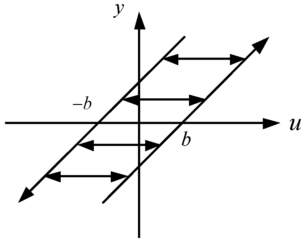
When a part generated from the input and transmitted to the output is transformed, if the corresponding reverse transformation is transmitted at the same time, the output also forms a change in the amount of change in the corresponding direction. However, if only the reverse change quantity is introduced, the output quantity does not immediately respond to the instantaneous change from the input side, but responds according to the output quantity until the input value exceeds a specific threshold [27]. The linear output signal generated by the system not only depends on the current linear input signal, but is also affected by the characteristics of the past input signal [28]. The historical input and output time characteristic curve of the nonlinear signals of clearance is shown in Figure 1 below.
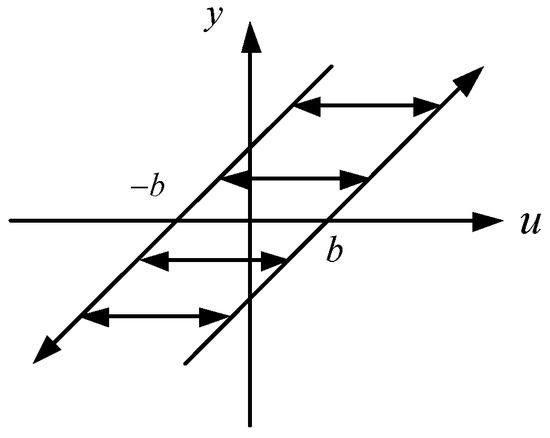
Figure 1.
Input and output characteristic curve of clearance characteristic.
The general mathematical model of clearance nonlinearity is shown below:
where:
- u—input signal;
- y—output signal;
- b—the size of the clearance;
- y(t−)—the output signal value at the previous time at time t.
The position function of the clearance is expressed as:
The clearance output formula is:
The position memory function of the clearance nonlinearity is expressed as:
The linear input signal and linear output of the clearance nonlinear system model are clearance displacements, so they directly reflect the linear displacement correspondence between the input signal and the system output. The output position signal of the memory link with the nonlinear memory characteristic of clearance at a certain time clearance is directly related to not only the input position signal, but the input position signal of each time clearance before the memory of a specific time clearance and its relationship with the historical position signal. There is also a direct correlation among the clearances, and this special property reflects the memorability of the clearance with nonlinear memory.
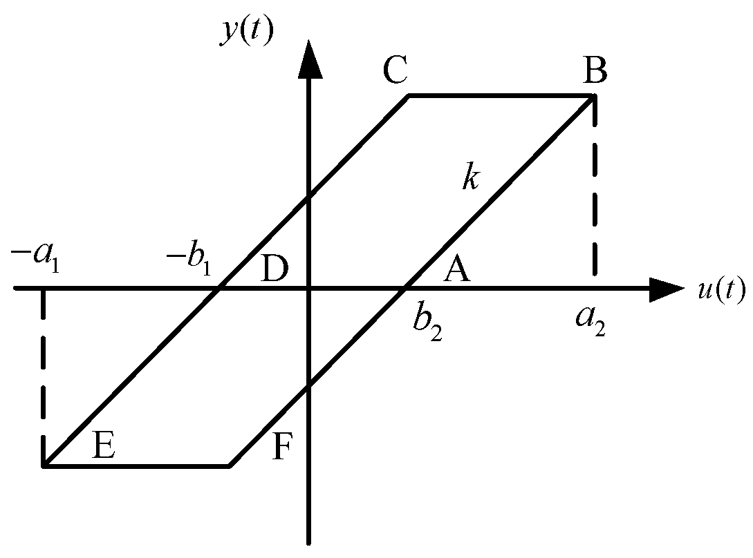
The active components need to be first connected to the follower through a certain distance to create a clearance. In this way, the follower can be activated and controlled, making the output signal of the system faster than its input signal [29]. As shown in Figure 2, its output may also occur with given parameters, indicating its multi-value nature; that is, its output is affected by the parameters, and its variations also become larger as the parameters increase [30].
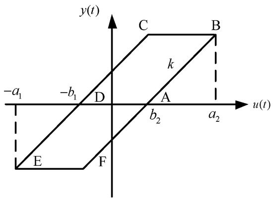
Figure 2.
Hysteresis model of clearance.
If an object moves to the right within the articulation clearance and the position of movement is lower than the articulation clearance, it will be in a stationary state. In this case, the object will be in the OA segment, which is the dead zone. However, if an object moves to the left, it will be pulled by an object, and in this case, the position of the object’s movement will change, and the speed of the object’s movement will slow down as the active components reach their lowest point. At this point, the driven component is in a stopped state, as shown in the BC section of the figure. However, once the active component is reconnected with the driven component, it is equivalent to the CE part, which pushes the driven component forward. The interval delay of this movement can be described by a simple formula:
where:
- x(t)—input displacement;
- y(t)—output displacement;
- al—maximum forward input;
- ar—maximum negative input;
- bl—left clearance amount;
- br—right clearance amount;
- k—transmission ratio of clearance input and output parts.
In the electro-hydraulic position servo system, if the clearance value between the piston rod of the hydraulic cylinder and the load exceeds the standard value, it will cause damage to the system stability during the movement of the hydraulic cylinder. Therefore, in the process of constructing an electro-hydraulic position servo system, due to the large inertia generated by the driven part, clearance nonlinearity must be considered.
2.2. Modeling of Electro-Hydraulic Servo System with Nonlinear Clearance
Theoretically speaking, the clearance is a kind of multi-value system nonlinear with typical characteristics in the hydraulic system. Usually, the clearance leads to the accumulation of additional system energy in the moving medium in the whole hydraulic system, and the accumulation of this additional energy easily leads to incomplete balance or oscillation in the hydraulic system. In the theoretical process of the mechanical hydraulic control system, the connection between the active-slave system and the driven motor part of the mechanical pair is often realized by the connection between the rotating pair and the spherical pair. Therefore, there must be a meshing clearance between the joints.
In fact, due to a series of internal reasons, such as large differences in surface processing and dimensional accuracy, installation and positioning mode accuracy, and different degrees of mechanical friction or wear, there is a certain radial sliding clearance coefficient between the load on the mechanism executing mechanical transmission and the actual machinery and the load system and its connection, which often varies greatly.
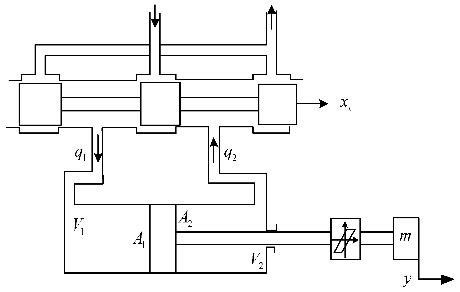
In hydraulic systems, the main and driven parts are usually connected by rotating pairs, ball pairs, and column pairs, but not directly. Because the interaction between the two leads to the need to use a tunable connection mode, the relationship between the two presents nonlinear characteristics. In the real hydraulic controller, the nonlinearity between the actuator and the load is usually significant due to the accuracy of the design, displacement error, consumption, and other problems. The basic form of the ideal load end clearance asymmetric hydraulic cylinder is shown in Figure 3. Set the movement to the right in the positive direction, and vice versa in the negative direction. According to the selected ratio , the flow relationship is:
where:
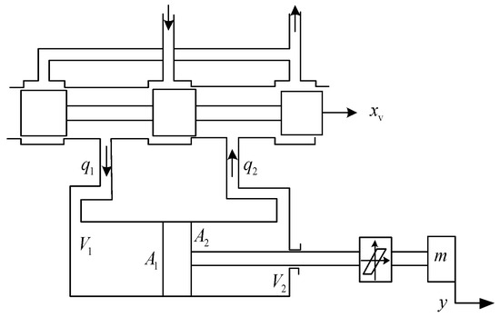
Figure 3.
The model of asymmetric cylinder system with flexible connection.
- q1—flow rate of a rodless chamber into asymmetric hydraulic cylinder, (L/min);
- q2—flow rate of rod cavity flowing out of asymmetric hydraulic cylinder, (L/min).
When the spool moves in the positive direction, the linearized flow continuity equation is:
where:
- qL—load flow, (m3/s);
- pL—load pressure drop, (Pa);
- xv—spool displacement, (m);
- Kc—flow pressure coefficient, (m3/s/Pa).
When the spool moves in the negative direction, the equation is:
The equation of positive motion is:
where:
- Ctc—the total leakage coefficient (m3/s/Pa);
- Ve—equivalent volume, (m3).
Similarly, the equation of positive motion is:
The force balance equation of asymmetric cylinder and load is:
Thus, the transfer function of positive motion is as follows:
Since there is no elastic load in the object driven by the hydraulic cylinder, the elastic load caused by the part material can be ignored. In addition, the viscous damping coefficient B is also very small. The piston speed caused by leakage is very small compared with the piston speed driven by oil flow, that is , so is ignored compared with 1.
It can be simplified as:
Similarly, the following transfer function can be obtained:
The parameter values of the actual hydraulic servo system are shown in Table 1.

Table 1.
Parameter value of hydraulic servo system.
3. Clearance Nonlinear Control Strategy Based on Hopfield Neural Network
3.1. Analysis of Clearance Changes at the Connection between the Load End and the Hydraulic Cylinder
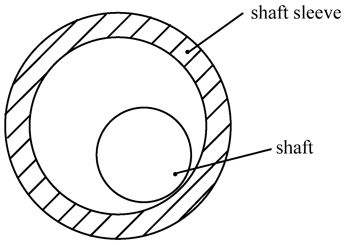
In the electro-hydraulic position servo system, the mechanism and load are generally connected by dynamically matched rotating pairs. However, due to issues such as equipment configuration clearances, design errors, and equipment damage, there is always a clearance at the equipment connection. The clearance model between the bearing and the shaft sleeve is shown in Figure 4. During this period, the load remains at a non-moving position, and when the bearing sleeve is in relative contact with the bearing, the load is pushed to the right. When the piston rod of the hydraulic cylinder retracts, the active part also needs to pass through clearance, and the bearing sleeve contacts the load, as shown in Figure 5.
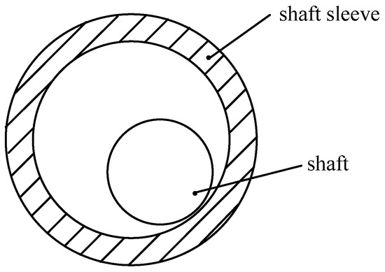
Figure 4.
Schematic diagram of rotating pair with clearance.

Figure 5.
Schematic diagram of clearance changes.
Due to the existence of nonlinear variables such as clearances, there is a negative impact on the dynamic function and reliable performance of the position feedback of the electro-hydraulic servo system [31,32]. Moreover, if the clearance value in the servo system can not be effectively controlled, the efficiency of the control system will gradually decrease. Therefore, finding an appropriate way to balance or reduce the adverse impact on the accuracy and efficiency of the system control caused by the clearance problem is the core challenge.
3.2. Clearance Compensation Control Based on Hopfield Network
The Hopfield network was developed by American physicist J. J. Hopfield, who first proposed it in 1982. Hopfield refers to a fully connected neural network, which simulates and studies the memory mechanism in the biological neural network system [33]. The “energy function” is used to intuitively present the dynamic stability of the artificial neural network system, thus providing a more reliable, accurate, practical, simple, and intuitive analysis basis for people to prove the dynamic stability of the neural network in the long-term operation state [34].
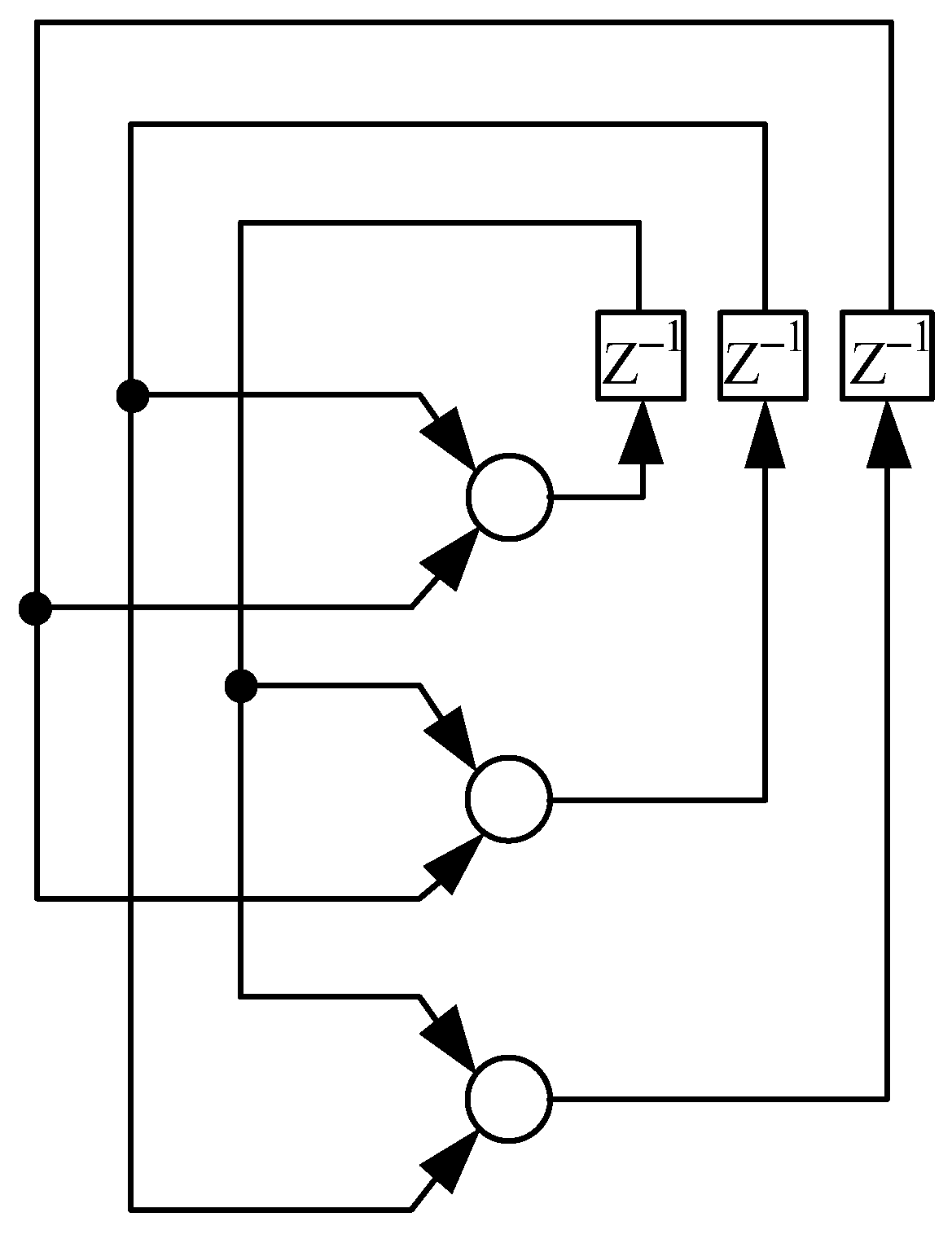
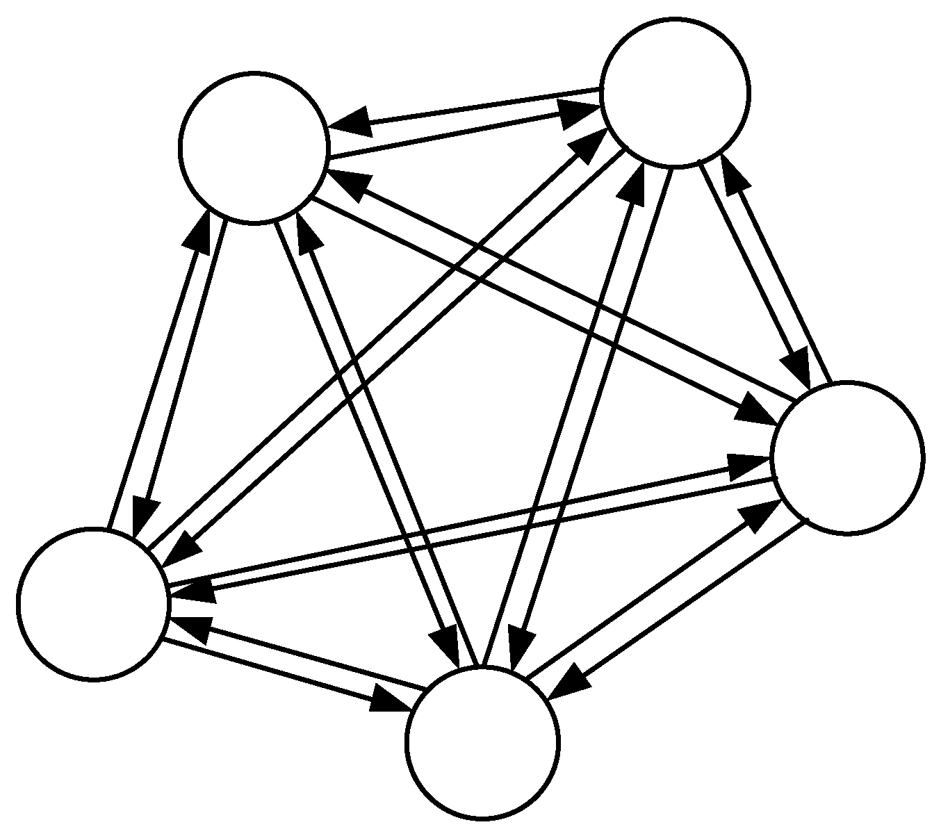
The Hopfield neural network model is mainly used to describe the establishment of a fully connected neural network containing feedback information. Its theoretical structure is shown in Figure 6. If there is only one input neuron level on the network, and the output of each neuron is connected to the input of other neurons, it is called a single-layer full feedback network. It is assumed that there are n neurons in this feedback neural network level, and each output neuron level is both an output neuron and an input neuron. All the two adjacent neurons in the network domain restrict each other. The weight of the connection between any two neurons i and j is defined as wij, and all the connections between these two neurons must be symmetric, that is, wij = wji [35,36]. Each neuron is also connected to one another as a single-layer fully interconnected network, as shown in Figure 7.
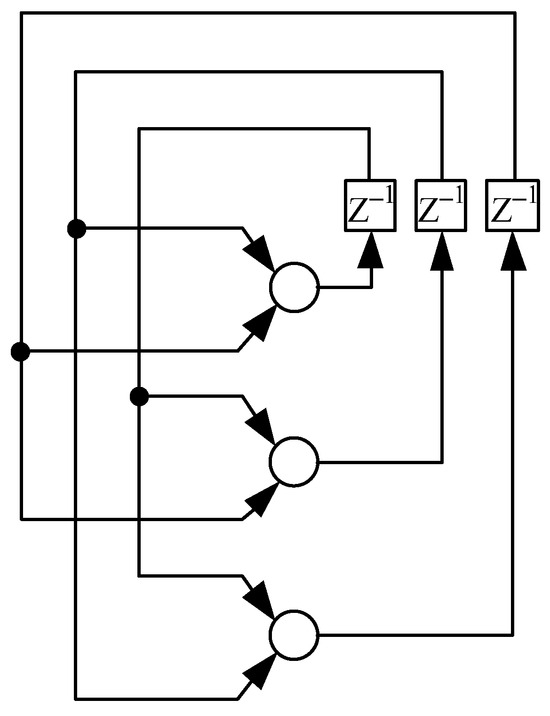
Figure 6.
Hopfield neural network.
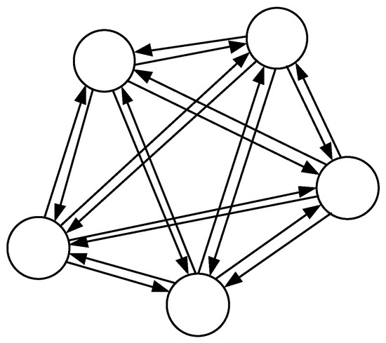
Figure 7.
Mesh structure of Hopfield network.
The value of the whole network state is X = [x1, x2, …, xn]T, and the initial value of the network state is X(0) = [x1(0), x2(0), …, xn(0)]T, that is, the input of the whole network. The network state is constantly changed and updated under the excitation of the new input signal, thus automatically generating the new output of the new signal. The network state and its evolution law are as follows:
where vj is a linear combination of the input domains of an induction network, which is referred to as the local domain of the induction network. bj refers to a fixed bias of an additional applied signal on the activated neuron j. The activated neuron function is defined as f (·).
The activation function adopts the symbolic function:
The Hopfield neural network system operates in the way of neurodynamic evolution. The working process is the evolution process of the initial state. For the initial operating state of a given system, it evolves in the way of capacity reduction and finally reaches a stable state. It can be seen from the analysis that it is very appropriate to use the nonlinear model of the hysteresis clearance problem to directly describe the delay clearance between the piston rod and the load of the position servo drive system.
When the piston rod passes through the clearance area, the clearance area is at the input end of the system, which changes in the clearance area, and indicates the existence of hysteresis nonlinearity. A more effective compensation technique for this change in the clearance area is to use the model compensation method. Due to the nonlinear variation in the clearance, this compensation technology cannot adjust in a timely manner according to the changing situation to prevent jitter and effectively adjust the clearance value or promptly correct its deviation through feedback.
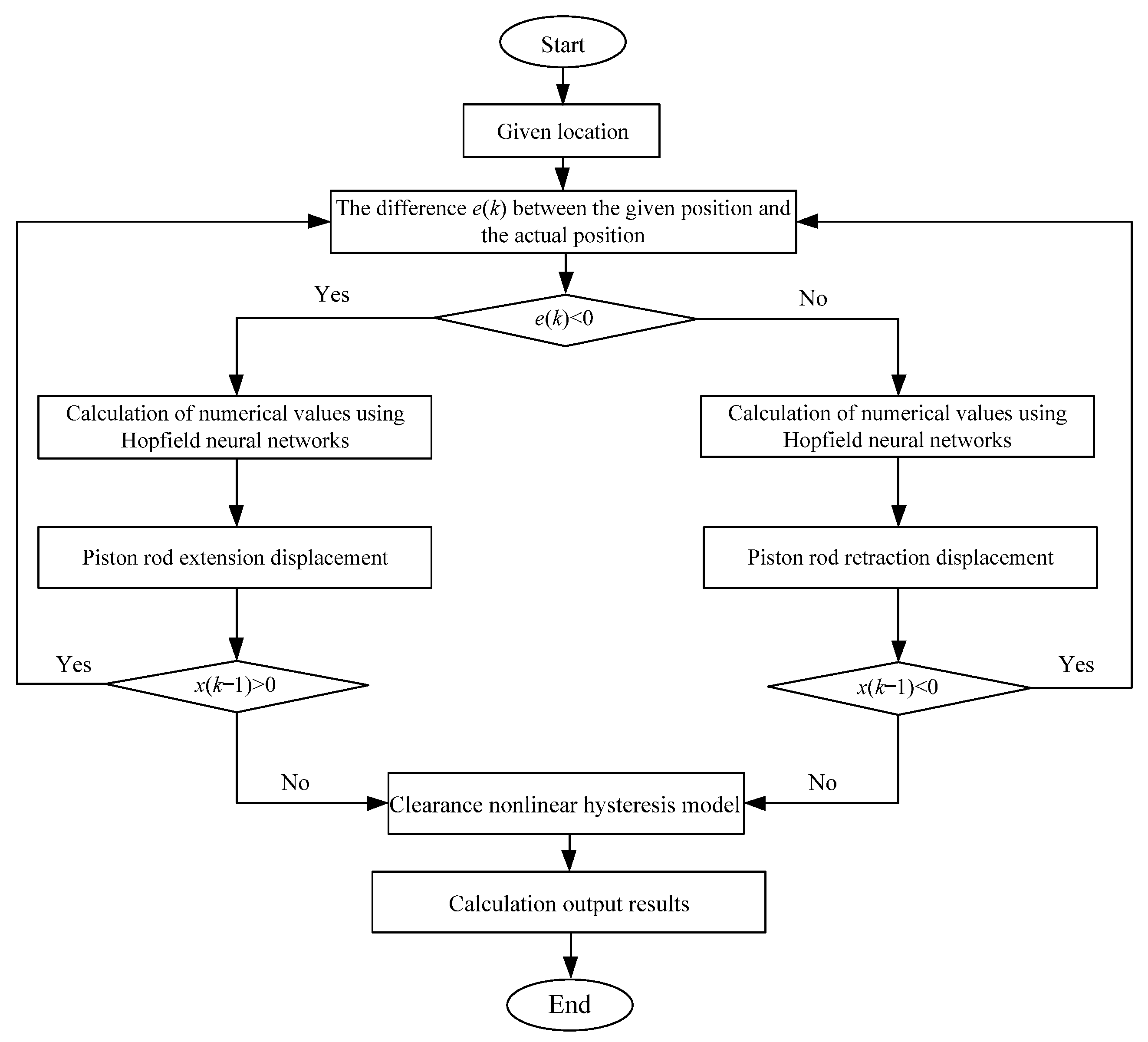
By introducing a fixed model compensation control algorithm, the negative impact caused by clearance delay can be effectively reduced. The algorithm process can be referred to in Figure 8. This algorithm needs to establish a reference point and calculate the distance between the reference point and the real point to obtain accurate control results. The model is as follows:
where:
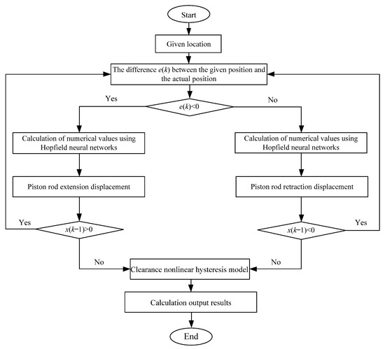
Figure 8.
Process block diagram.
- g(τ, t)—vertical jump, g(τ, t) = m(b1 + b2)δ(τ − t);
- δ(t)—Dirac δ function.
The clearance nonlinear hysteresis model under discrete time can be represented as:
By using the Hopfield neural network algorithm, the operation of the electro-hydraulic servo system can be effectively controlled, and the specific control structure can be seen in Figure 9. This algorithm can adjust the node parameters of the feedback neural network, and use a servo controller to control the valve core of the servo valve, effectively controlling the operation of the hydraulic cylinder. It can also convert the abnormal values of input and output into error feedback, effectively suppressing the clearance changes in the system and reducing the adverse impact of the clearance on the model results.

Figure 9.
Block diagram of an electro-hydraulic servo system with nonlinear clearance model control.
4. Clearance Nonlinear Compensation Control Based on Hopfield Neural Network
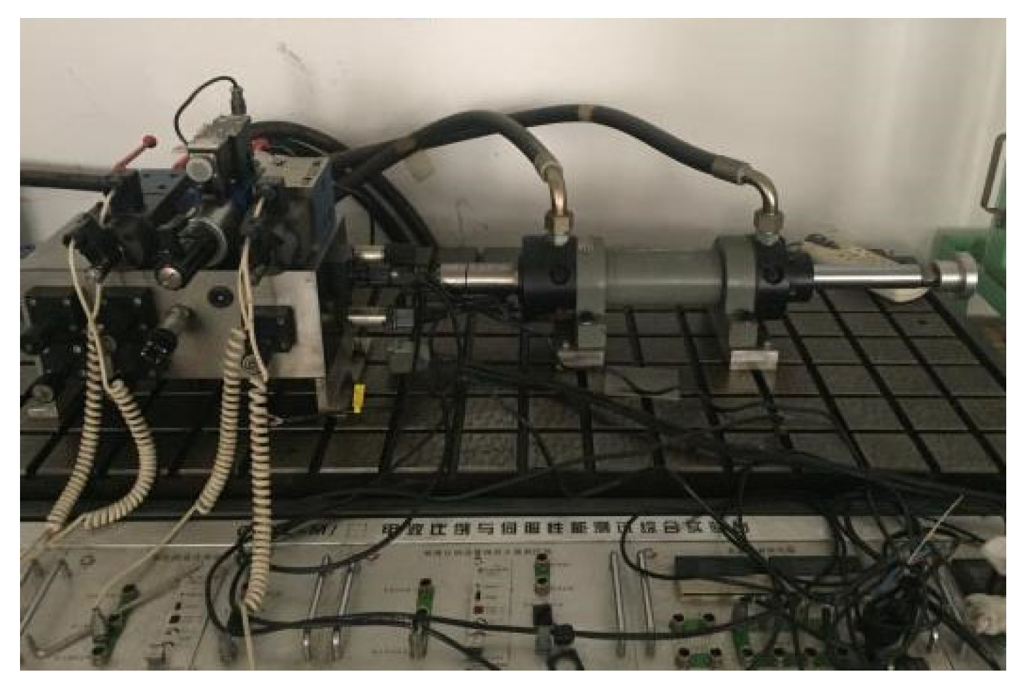
This platform is based on virtual instrument technology to build an auxiliary measurement tool, which makes full use of the computer’s efficient computing power and large capacity storage space to achieve the role of measurement equipment. By providing the input signal, the requirements of the system for dynamic characteristics are met. The core technology of this platform is that it can perform tasks such as high-frequency data interaction, collection, inspection, management, and data analysis, as shown in Figure 10. This experimental platform is mainly composed of a hydraulic station, servo valve-controlled hydraulic cylinders, loads, various sensors, and data acquisition cards. In order to deeply understand how clearance affects the nonlinear problem of the electro-hydraulic servo control system, an electro-hydraulic servo control platform with clearance was built, as shown in Figure 11.

Figure 10.
Control system of electro-hydraulic servo system.
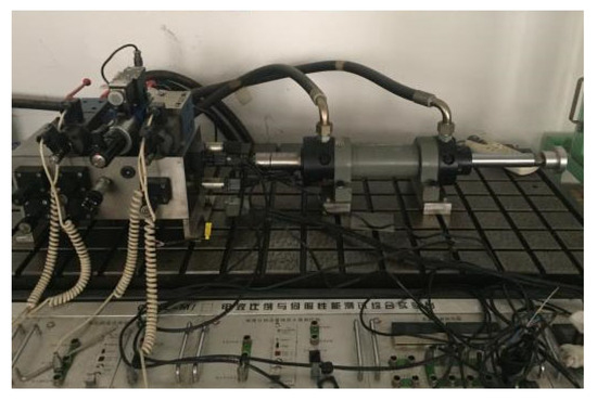
Figure 11.
Applied electro-hydraulic servo system.
The entire operation process is mainly composed of three parts: a data acquisition module, a measurement control module, and an experimental system. The data acquisition module uses sensors for digital measurement and amplification, which performs an analog-to-digital conversion in the digital acquisition card before sending it to the computer. The control system mainly utilizes a computer to control the entire system, achieve digital to analog conversions, and generate analog signals, which are amplified by amplifiers and sent to the electro-hydraulic servo system on the platform to complete the control system.
From the above research methods, it can be seen that if there is a clearance problem at the connection between the hydraulic cylinder and the load, it leads to a nonlinear relationship between the active and passive components, which affects the output performance of the entire hydraulic system. Once an impact occurs, the system is subject to significant interference, resulting in stable deviations. With the expansion of the system clearance, it may cause limit cycle oscillation, which causes serious damage to the dynamic performance of the controller. In order to explore the interaction between various sizes of clearances and the system in the actual use process, the mathematical model of different sizes of clearances between the shaft sleeve and the load connecting the shaft is established.
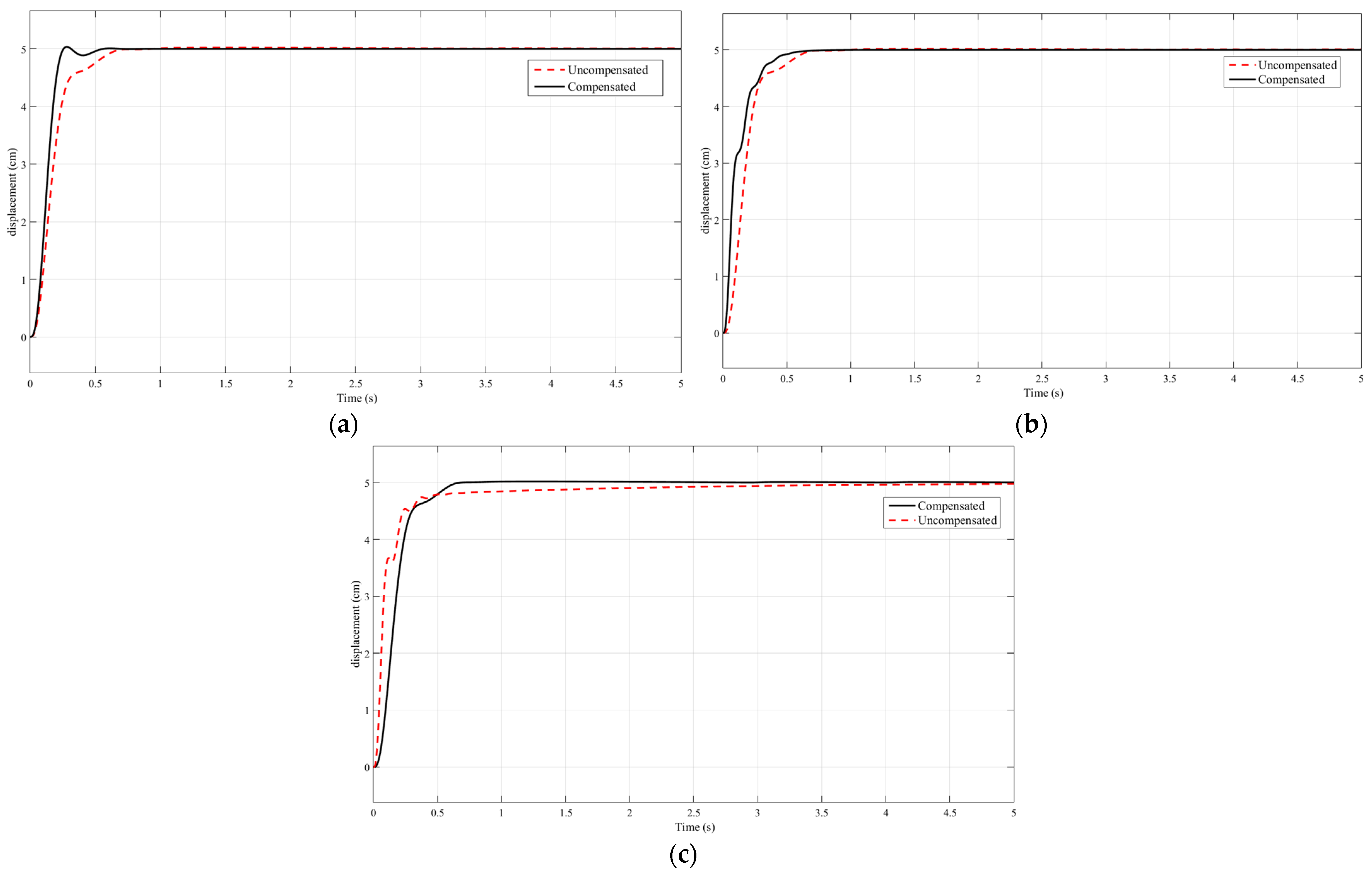
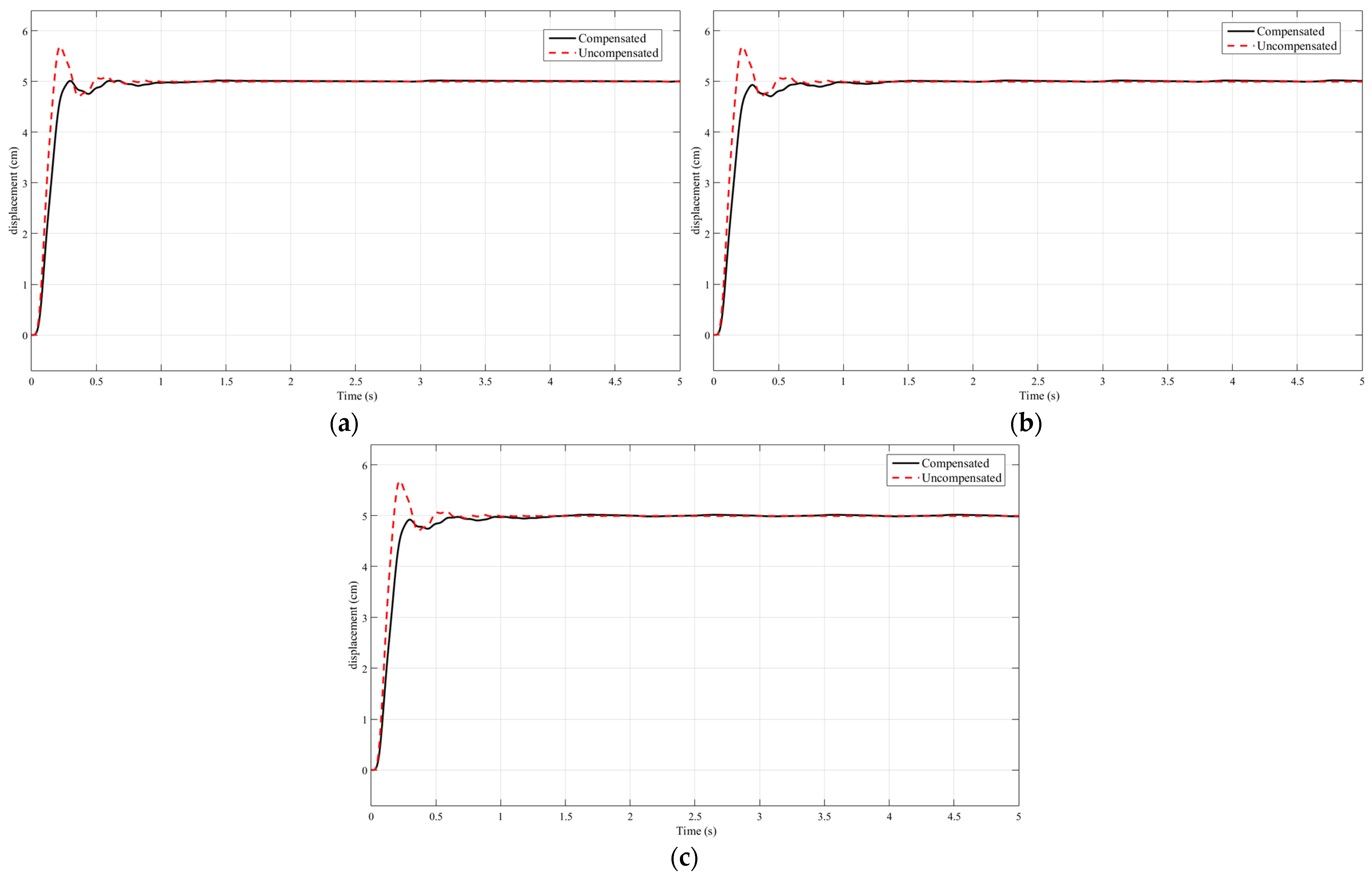
In order to verify the proposed compensation of clearance nonlinearity based on the Hopfield neural network, the step response signal is applied to the electro-hydraulic servo system, and the effect on the system after compensation is observed. Taking the extension movement of the asymmetric hydraulic cylinder as an example, the clearance values are set as 0.1, 0.5, and 1 mm, respectively, and the step response comparison is shown in Figure 12, where the black solid line represents compensation and the red dashed line represents uncompensated. Similarly, when an asymmetric hydraulic cylinder undergoes a retraction motion. The clearance value setting is the same as that of the hydraulic cylinder during the extension movement. The comparison of step response is shown in Figure 13, where the black solid line represents compensation and the red dashed line represents uncompensated. Observe the difference after the comparison of the lines in the figure.
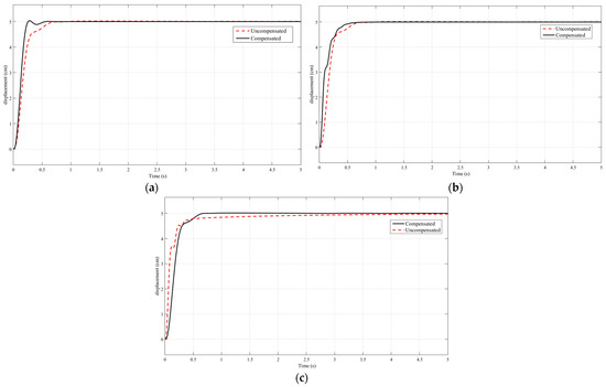
Figure 12.
Comparison diagram of system step response curve between uncompensated clearance and compensated clearance during extension movement: (a) The clearance value is 0.1 mm; (b) the clearance value is 0.5 mm; (c) the clearance value is 1 mm.
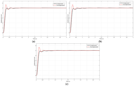
Figure 13.
Comparison diagram of system step response curve between uncompensated clearance and compensated clearance during retraction movement: (a) The clearance value is 0.1 mm; (b) the clearance value is 0.5 mm; (c) the clearance value is 1 mm.
It can be seen from the comparison simulation results that after the clearance nonlinearity is compensated, the step response curve of the asymmetric hydraulic cylinder’s extension motion is well improved, the overshoot is reduced, and the oscillation amplitude is reduced, and there will be no small oscillation after reaching stability. The same is true when the asymmetric hydraulic cylinder is retracted. Through the analysis, it can be concluded that the potential influence of the clearance nonlinear system and the dynamic performance change of the control system can be well eliminated by constructing a Hopfield neural network clearance compensator.
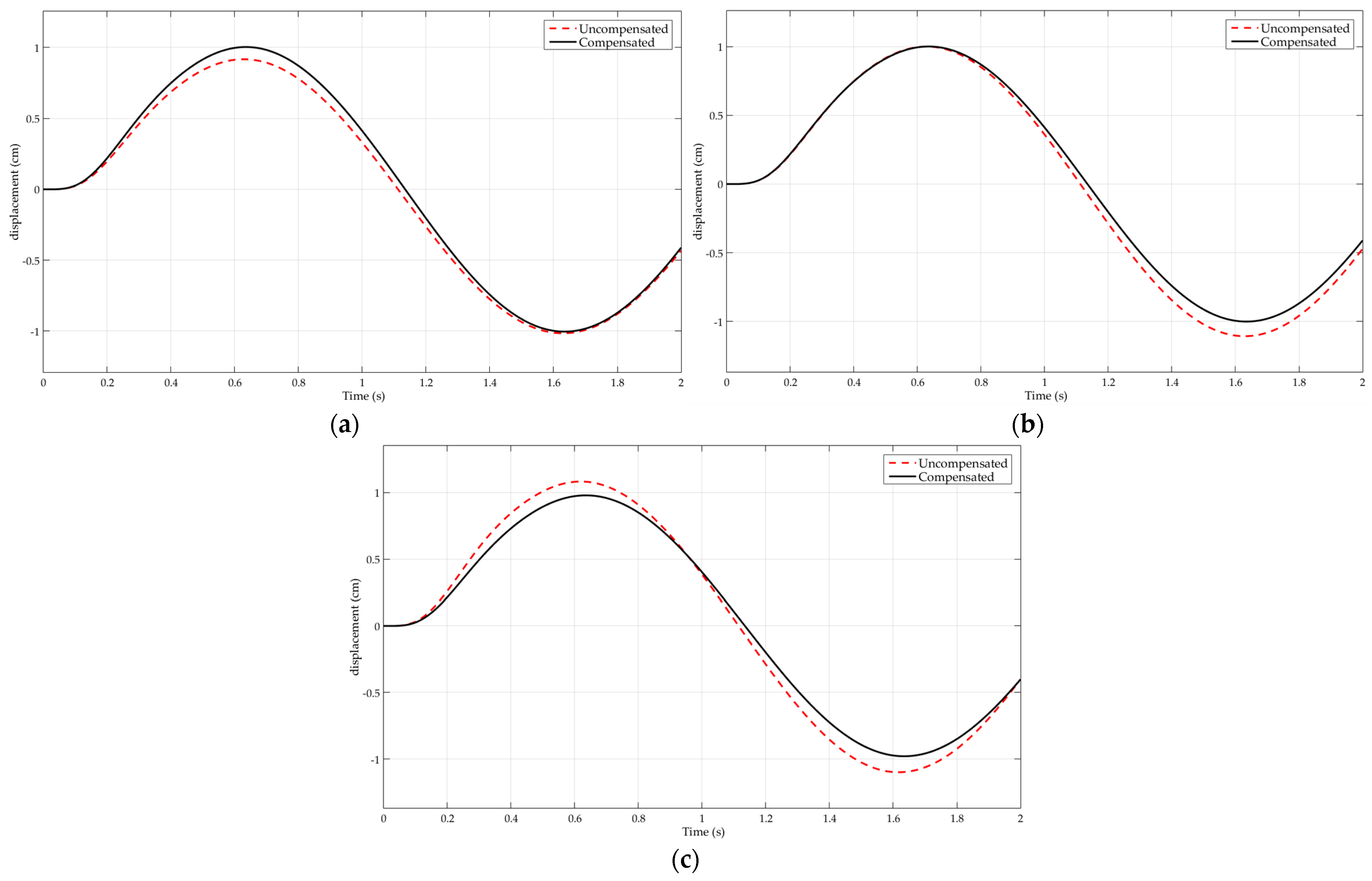
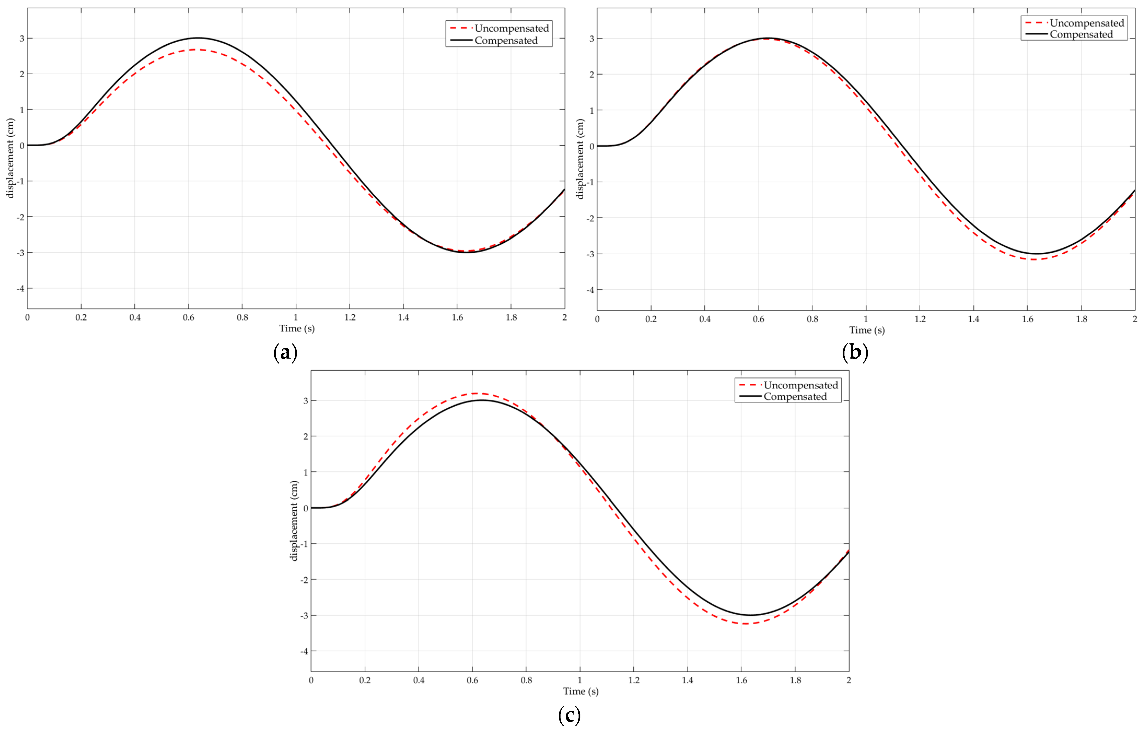
As shown in Figure 14 where the black solid line represents compensation and the red dashed line represents uncompensated, when the displacement of the system’s sinusoidal output reaches 1 cm, a corresponding attenuation phenomenon occurs in the clearance after the system operates normally. When the sinusoidal output displacement reaches 3 cm, the corresponding curve appears in the clearance after the normal operation of the system in Figure 15. When the input signal waveform reaches its peak, a significant amount of error is produced in the output waveform due to the influence of the system clearance. However, the output curve does not start tracking the input signal again until the piston rod completes the clearance work. After completing the clearance compensation work, the attenuation phenomenon has been improved and the accuracy of the feedback waveform provided by the system has basically met the requirements. At the same time, the tracking stability of the system and its reproducibility of system signals have been significantly improved. Based on this, it can be concluded from the comparison simulation results that the constructed control compensation algorithm can reduce the negative effect caused by the reduction of the output signal amplitude caused by the clearances in the process of sinusoidal system signal, so as to enhance the tracking accuracy of the control system. It has a good supplementary effect on the nonlinearity problem caused by clearances in the transmission process of the servo system. According to the phenomenon, the system clearance has little effect on the step signal because the effect of the clearance is smaller when the hydraulic cylinder is in the body movement than when it is in the cable back movement, but when the hydraulic cylinder is in the round-trip movement, the effect is more obvious.
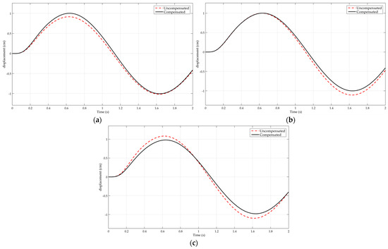
Figure 14.
Comparison of the sine signal curves (1 cm) of the system output between the uncompensated clearance and the compensated clearance: (a) The clearance value is 0.1 mm; (b) the clearance value is 0.5 mm; (c) the clearance value is 1 mm.
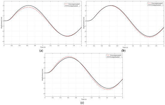
Figure 15.
Comparison of the sine signal curves (3 cm) of the system output between the uncompensated clearance and the compensated clearance: (a) The clearance value is 0.1 mm; (b) the clearance value is 0.5 mm; (c) the clearance value is 1 mm.
5. Conclusions
The clearance nonlinearity of the electro-hydraulic servo system in many transmission links, especially the clearance between the piston rod of the hydraulic cylinder and the load, is mainly the actual value of the control clearance coefficient. Because it continues to change with the specific operation characteristics of the control equipment components, it is of great practical value to study the control attributes of the dynamic system, including the clearance.
In the paper, the common servo driver configuration in the electro-hydraulic servo system is simplified, and it is converted to a typical valve controlled hydraulic cylinder mode, and the mathematical model of the system is constructed, the transfer function of system parameters is solved, and a numerical simulation model of those system parameters is obtained based on the electro-hydraulic servo mechanism. Based on the influence of clearance nonlinearity on the step responses of the electro-hydraulic servo system, the Hopfield neural network control strategy is adopted to compensate for the control of the system. The simulation results show that the oscillation of the step response curve and overshoot is reduced, with the adjustment time reduced accordingly. It is proved that the Hopfield neural network method has better control performance and certain practical values.
Using the method of system analysis, the interaction between the electro-hydraulic servo device and the nonlinear hydraulic controller is studied, and a compensation mode with clearance is constructed. The clearance between the systems is adjusted and corrected, and good control results are achieved. However, there are still some problems to be solved. For the interval nonlinear characteristics in the electro-hydraulic servo system, this part focuses on the clearance between the piston rod and the load, rather than the clearance caused by other components. These aspects need to be further explored. In addition, the input and output data are only a single value, and in the real environment, it often involves multiple groups of data. At this point, the phenomenon of clearance influence becomes even more complex, and further research is needed in future practical engineering.
Author Contributions
Conceptualization, T.W. and J.S.; methodology, T.W. and J.S.; software, T.W. and J.S.; validation, T.W. and J.S.; formal analysis, T.W. and J.S.; resources, T.W. and J.S.; writing—original draft preparation, T.W.; writing—review and editing, T.W.; funding acquisition, T.W. and J.S. All authors have read and agreed to the published version of the manuscript.
Funding
This research was funded by the scientific research support plan of Shenyang Ligong University to introduce high-level talents, grant number 1010147001113.
Data Availability Statement
Due to privacy, confidentiality, or ethical considerations, the data underlying the findings of this study cannot be made publicly available. We respect and uphold the privacy and rights of all participants involved, and therefore, the raw data cannot be shared. We appreciate your understanding and respect for these constraints.
Acknowledgments
The authors would like to thank the professors and reviewers for their professional and helpful comments.
Conflicts of Interest
The authors declare no conflict of interest.
References
- Ziaei, K.; Sepehri, N. Modeling and Identification of Electro-hydraulic Servos. Mechatronics 2010, 10, 761–772. [Google Scholar] [CrossRef]
- Yao, J.Y. Model-based nonlinear control of hydraulic servo systems: Challenges, developments and perspectives. Front. Mech. Eng. 2018, 13, 179–210. [Google Scholar] [CrossRef]
- Wen, S.; Yu, H.; Zhang, B.; Zhao, Y.S.; Lam, H.K.; Qin, C.Q. Fuzzy Identification and Delay Compensation based on the Force/Position Control Scheme of the 5-DOF Redundantly Actuated Parallel Robot. Int. J. Fuzzy Syst. 2017, 19, 124–140. [Google Scholar] [CrossRef]
- Hao, Y.; Quan, L.; Qiao, S.; Xia, L.; Wang, X. Coordinated Control and Characteristics of an Integrated Hydraulic-Electric Hybrid Linear Drive System. IEEE/ASME Trans. Mechatron. 2021, 27, 1138–1149. [Google Scholar] [CrossRef]
- Brylina, O.G. Influence of the pattern of pulse-width and frequency-pulse-width modulation on the ripple level of the output signal of the first-order aperiodic link. Russ. Electr. Eng. 2014, 85, 604–609. [Google Scholar] [CrossRef]
- Hsieh, C.T.; Lai, C.P. Nonlinear dynamic analysis and control of a hydraulic press electro-hydraulic servo system. J. Low Freq. Noise Vib. Act. Control 2018, 38, 1594–1606. [Google Scholar] [CrossRef]
- Ba, D.X.; Dinh, T.Q.; Bae, J.; Ahn, K.K. An Effective Disturbance-Observer-Based Nonlinear Controller for a Pump-Controlled Hydraulic System. IEEE/ASME Trans. Mechatron. 2019, 25, 32–43. [Google Scholar] [CrossRef]
- Simon, S.A.; Clemens, C.M.; Wolfgang, E.C.; Alexander, F.A.; Christoph, H. Two-degree-of-freedom MIMO control for hydraulic servo-systems with switching properties. Control Eng. Pract. 2020, 95, 104246. [Google Scholar]
- Park, C.G.; Yoo, S.; Ahn, H.; Kim, J.; Shin, D. A coupled hydraulic and mechanical system simulation for hydraulic excavators. Proc. Inst. Mech. Eng. Part I J. Syst. Control Eng. 2020, 234, 527–549. [Google Scholar] [CrossRef]
- Maghareh, A.; Silva, C.E.; Dyke, S.J. Parametric model of servo-hydraulic actuator coupled with a nonlinear system: Experimental validation. Mech. Syst. Signal Process. 2018, 104, 663–672. [Google Scholar] [CrossRef]
- Yang, M.; Hao, L.; Xu, D.G. Analysis of mechanical resonance mechanism and fast identification of resonance characteristic for 2-mass system with elastic load. Electr. Mach. Control 2007, 20, 112–120. [Google Scholar]
- Sun, C.; Yuan, R. Adaptive robust cross-coupling position synchronization control of a hydraulic press slider-leveling. Sci. Prog. 2021, 104, 82–89. [Google Scholar] [CrossRef] [PubMed]
- Katsura, S.; Ohnishi, K. Vibration Control of Multi-Mass Resonant System Based on Phase-Lead Compensator. IEEJ Trans. Ind. Appl. 2006, 126, 1601–1607. [Google Scholar] [CrossRef]
- Ni, T.W.; Yang, Z.G. Failure analysis on unexpected leakage of electro-hydraulic servo valve in digital electric hydraulic control system of 300 MW thermal power plant. Eng. Fail. Anal. 2021, 119, 104992. [Google Scholar] [CrossRef]
- Bing, X.; Qi, S.; Zhang, J.; Lu, Z. A dead-band model and its online detection for the pilot stage of a two-stage directional flow control valve. Arch. Proc. Inst. Mech. Eng. Part C J. Mech. Eng. Sci. 2016, 230, 1989–1996. [Google Scholar]
- Guo, J.; Yang, J. Adaptive dynamic friction compensation control of electrohydraulic servo system. In Proceedings of the 10th World Congress on Intelligent Control and Automation, Beijing, China, 6–8 July 2012. [Google Scholar]
- Liu, C.; Jiang, Y.; Zhang, Z.; Deng, T.; Yu, D.; Gao, J. Research on Electro-hydraulic Servo System of Air Rudder on Model Reference Adaptive Control. J. Phys. Conf. Ser. 2020, 1650, 022001. [Google Scholar] [CrossRef]
- Hayama, Y.; Nishizaki, J.; Teramoto, Y.; Mohri, A. Stability Analysis of Roll Gap Control System on Rolling Mill in Non-Rolling State. Trans. Jpn. Soc. Mech. Eng. 2000, 66, 759–764. [Google Scholar] [CrossRef][Green Version]
- Dinh, B.K.; Xiloyannis, M.; Cappello, L.; Antuvan, C.W.; Yen, S.-C.; Masia, L. Adaptive backlash compensation in upper limb soft wearable exoskeletons. Robot. Auton. Syst. 2017, 92, 173–186. [Google Scholar] [CrossRef]
- Yang, J.; Tan, J.; Shu, Z. Online compensation of gap in large hydraulic press operation system. Zhongnan Daxue Xuebao (Ziran Kexue Ban)/J. Cent. South Univ. (Sci. Technol.) 2015, 46, 479–484. [Google Scholar]
- Li, J.; Zhao, Z.; Wang, Y.; Wang, X.J.; Han, G.H.; Li, S.M.; Dong, F.T. Research on electro-hydraulic force servo system and its control strategy considering transmission clearance and friction. Acta Tech. CSAV (Ceskoslovensk Akad. Ved) 2016, 61, 207–218. [Google Scholar]
- Zeng, Q.; Li, Y.; Yang, Y. Dynamic Analysis of Hydraulic Support with Single Clearance. Fac. Mech. Eng. 2021, 67, 53–66. [Google Scholar] [CrossRef]
- Knežević, D.M.; Milašinović, A.N.; Milovanović, Z.N.; Laloš, S.S. The influence of thermodynamic state of mineral hydraulic oil on flow rate through radial clearance at zero overlap inside the hydraulic components. Therm. Sci. 2017, 20 (Suppl. S5), 1461–1471. [Google Scholar] [CrossRef]
- Zhang, J.; Zhou, C.; Jiang, Z.; Wang, Y.; Sun, X. Optimization Design of Actuator Parameters with Stepless Capacity Control System Considering the Effect of Backflow Clearance. Appl. Sci. 2020, 10, 2703. [Google Scholar] [CrossRef]
- Chen, X.; Jiang, S. Nonlinear dynamic behavior analysis of multi-linkage mechanism with multiple lubrication clearances. Eur. J. Mech. B Fluids 2022, 91, 177–193. [Google Scholar] [CrossRef]
- Ma, J.; Qian, L. Modeling and simulation of planar multibody systems considering multiple revolute clearance joints. Nonlinear Dyn. 2017, 90, 1907–1940. [Google Scholar] [CrossRef]
- Zahid, M.H.; Ovy, E.G. Coupling Effects on Torsional Vibration with Clearance of a Two-Degree-of-Freedom System. Adv. Mater. Res. 2011, 199–200, 824–830. [Google Scholar] [CrossRef]
- Kim, T.C.; Rook, T.E.; Singh, R. Super- and sub-harmonic response calculations for a torsional system with clearance nonlinearity using the harmonic balance method. J. Sound Vib. 2005, 281, 965–993. [Google Scholar] [CrossRef]
- Aoki, S.; Watanabe, T. Practical Response Analysis of a Mass-spring Impact System with Hysteresis Damping. Nucl. Eng. Des. 2003, 234, 1–9. [Google Scholar] [CrossRef]
- Aoki, S.; Watanabe, T. Practical Response Analysis of a Simply Supported Beam with Clearance and Hysteresis Damping. In Proceedings of theTransaction SMiRT 16, Washington, DC, USA, 12–17 August 2001. [Google Scholar]
- Baragetti, S.; Villa, F. Effects of geometrical clearances, supports friction, and wear rings on hydraulic actuators bending behavior. Math. Probl. Eng. 2016, 2016, 3781397. [Google Scholar] [CrossRef]
- Nikas, G.K. Analytical study of the extrusion of rectangular elastomeric seals for linear hydraulic actuators. Proc. Inst. Mech. Eng. Part J J. Eng. Tribol. 2003, 217, 365–373. [Google Scholar] [CrossRef]
- Kumar, S.S.; Palanisamy, V. A dynamic programming based fast computation Hopfield neural network for unit commitment and economic dispatch. Electr. Power Syst. Res. 2007, 77, 917–925. [Google Scholar] [CrossRef]
- Kobayashi, M. Diagonal Rotor Hopfield Neural Networks. Neurocomputing 2020, 415, 40–47. [Google Scholar] [CrossRef]
- Kasihmuddin, M.S.N.; Mansor, M.A.; Basir, M.F.M.; Sathasivam, S. Discrete Mutation Hopfield Neural Network in Propositional Satisfiability. Mathematics 2019, 7, 1133. [Google Scholar] [CrossRef]
- Silva, H.O.; Bastos, C.J.A. Inter-domain routing for communication networks using Hierarchical Hopfield Neural Networks. Engineering Applications of Artificial Intelligence. Int. J. Intell. Real-Time Autom. 2018, 70, 184–198. [Google Scholar]
Disclaimer/Publisher’s Note: The statements, opinions and data contained in all publications are solely those of the individual author(s) and contributor(s) and not of MDPI and/or the editor(s). MDPI and/or the editor(s) disclaim responsibility for any injury to people or property resulting from any ideas, methods, instructions or products referred to in the content. |
© 2024 by the authors. Licensee MDPI, Basel, Switzerland. This article is an open access article distributed under the terms and conditions of the Creative Commons Attribution (CC BY) license (https://creativecommons.org/licenses/by/4.0/).

