Abstract
Vibration in hot tandem rolling mills has been a problem in the iron and steel industry mainly due to its unpredictability. In this work, vibration data of the second finishing mill (F2) stand of a hot tandem rolling mill are collected and analyzed, and a mathematical model based on the coupling of a non-uniform deformation process, mill structure and hydraulic control system is constructed. The influence of different inlet thickness fluctuation forms, structural parameters and control parameters on the vibration behavior is analyzed. It is concluded that the low-frequency thickness fluctuation with additional skewness can cause the resonance of each subsystem of the rolling mill. The deviation angle of the roll system influences the vibration harmonic output of the rolling mill under a single low-frequency thickness fluctuation excitation. The compensation parameter in the thickness control system affects the natural frequency of the vertical system.
1. Introduction
The mill vibration problem has troubled the steel industry for decades and its occurrence is often accompanied by a variety of rolling process conditions. Violent vibration negatively impacts the mill itself and the surface quality of the strip. Some scholars believe that mill vibration is the loss of stability caused by negative system damping. Yarita et al. [1] first made a theoretical analysis of this view. Tlusty et al. [2] attributed the negative damping to the tension fluctuation of the strip. Yun et al. [3,4,5] analyzed the negative damping mechanism of modal coupling and regenerative vibration. Gao et al. [6] studied the critical rolling speed under the negative damping mechanism. Heidari et al. [7] optimized the process parameters of rolling and improved the rolling speed limited by flutter. Some scholars believe that there are coupling mechanisms in the rolling mill vibration. Zheng et al. [8] considered that the mill vibration included multimode coupling such as vertical, horizontal, axial and torsional vibrations. Wang et al. [9] used the harmonic response method of ANSYS to study the amplitude-frequency characteristics of the vertical-torsion coupling system. Jia et al. [10] studied the effect of dynamic stiffness compensation on the electromechanical coupling vibration of a rolling mill. Cui et al. [11] studied the rigid–flexible coupling problem between rolling mill and strip vibration. The mill vibration will appear as nonlinear behavior, so some scholars focus on the study of mill nonlinear vibration. Peng et al. [12] analyzed the vibration characteristics of a hot rolling mill with elastoplastic hysteresis deformation. Liu et al. [13] analyzed the influence of time-varying bearing stiffness on rolling mill vibration. Zeng et al. [14] analyzed the Hopf bifurcation of mill vibration caused by nonlinear friction. Kapil et al. [15] considered the influence of strip vibration on work roll vibration and established the motion control equation of a nonlinear parameter excitation system. Hou et al. [16] established the nonlinear dynamic rolling force in vertical and horizontal directions, respectively, and considered the influence of vertical and horizontal vibration of roll.
The above research is aimed at vibration at a certain frequency or a small range of frequencies. This work focuses on the generation and influencing factors of harmonics in the vibration process. In this work, the vibration state of the rolling mill is monitored over a long period of time and a multi-system dynamic coupling model is constructed based on the rolling mill structure, non-uniform deformation process and control process. The model is used to study the vibration response characteristics of rolling mills under different inlet thickness fluctuation modes, as well as the influence of the mill structure and control parameters on the mill vibrations. The phenomenon of the occurrence and increase of harmonics in the frequency spectrum during the development of vibration is observed in the experiment. Based on this phenomenon, different from previous studies, this work focuses on the mechanism of low-frequency thickness fluctuation generating harmonics and stimulating high-frequency vibration of rolling mills.
2. Experiments
Severe mill vibration occurs in industrial sites. In order to analyze the vibration characteristics of the rolling mill, the top of the rolling mill, the bearing seat of the work roll and the process parameters are obtained by the experimental test method, and the time–frequency characteristics are extracted by the FFT.
The installation of the measuring points is shown in Figure 1. The vibration speed sensor on the top of the mill is used to detect the vertical vibration of the mill, the horizontal vibration of the work roll can be approximated with the sensor on the bearing seat and the torque tester on the drive shaft can detect the rolling torque. After data collection, subsequent data analysis is carried out through calculation. Other rolling process parameters can be obtained from the PLC.
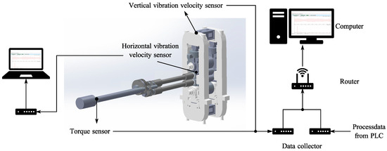
Figure 1.
Schematic of the sensor installation.
The vibration monitoring results show that the vibration of the second finishing mill (F2) is the most intense and the strip steel at the exit and work rolls have clear traces of vibration, as shown in Figure 2. When rolling low alloy steel Q235B strips with different thicknesses and rolling speeds, the vibration of the F2 is monitored and the vertical vibration speed signal at the top of the frame is analyzed as shown in Figure 3b. With the rolling process, the vibration state of the rolling mill has changed. Before 700 s, the vibration is dominated by a single fundamental frequency of about 20 Hz, and higher harmonics gradually appear in the range of 1000–3000 s. After 3000 s, the violent vibration stabilizes at about 3 times the fundamental frequency, that is, at about 60 Hz. The development process of vibration corresponds to the generation of harmonics, so this work studies the factors that may affect the high-order harmonics in the process of vibration by establishing a mathematical model of the dynamic rolling process.

Figure 2.
Roller and strip vibration traces: (a) roller vibration traces; (b) strip vibration traces.
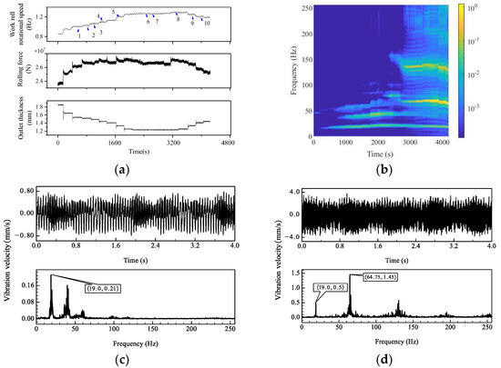
Figure 3.
Vibration state of rolling mill when rolling Q235B: (a) the rolling process parameters; (b) the spectrum varies with time; (c) period 4 vibration curve; (d) period 10 vibration curve.
3. Model Establishment and Verification
It is found that the development of mill vibration is accompanied by the generation of high-order harmonics, and this process must be related to the performance of the mill itself and the dynamic rolling process between the work rolls. In this chapter, the dynamic rolling process model and the multi-system coupling model of the mill structure–control are established and verified. Dynamic rolling force and rolling moment are used to link the two models. The natural frequency, mode and natural frequency sensitivity to the structural parameters of the system are analyzed, and the influence of strip fluctuation performance, mechanical structure and control parameters on the vibration of the rolling mill is studied.
3.1. Rolling Process Model
First, reasonable assumptions are made according to the actual rolling process: 1. All plastic deformations occur in the deformation zone; 2. Since the width of the strip in the deformation zone is much larger than the dimensions in the other two directions, it is considered that the deformation zone can be approximated to the plane strain state; 3. τxy is the shear stress in the xy plane, which is assumed to be linearly distributed vertically from the center of the strip thickness; 4. σyy is the normal stress in the y direction, assuming that it is a constant along the vertical direction. The x direction represents the horizontal direction of rolling, the y direction represents the vertical direction of rolling and the z direction represents the axial direction. According to the above conditions, the Von Mises yield condition can be obtained:
Here, σs and τs are tensile and shear yield strength, respectively, and J2dev is the second invariant of stress eccentricity. σxx, σyy, σzz, τxy, τxz and τyz are the stress components in each direction.
k is the yield limit of the strip. Assuming the intermediate stress σzz = 0.5(σxx + σyy), based on the plane strain condition, that is, τyz = τxz = 0, then the yield condition becomes:
At the delivery side of the deformation zone, the stress state of the strip at the rolling interface is shown in Figure 4a. pdel represents the normal stress of the strip surface at the delivery side and τdel represents the tangential stress generated by friction.
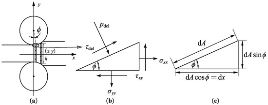
Figure 4.
Schematic diagram of surface stress on the unit body on the delivery side: (a) rolling scheme; (b) surface stress; (c) unit body side length.
The surface force diagram of the unit element with length dx at x distance from the rolling exit in the rolling direction is shown in Figure 4b. The analysis is carried out according to the normal and tangential directions of the surface. The force balance equation is as follows:
By combining Equations (3) and (4), the solution is as follows:
In the equation, α = arcsin (τdel/k). According to the above solution results and assumptions 2 and 3, the stress field at any point in the deformation region is:
where h is the thickness of the strip at x length from the rolling exit and y is the distance from the central symmetric line of the strip. As shown in Figure 5, according to the stress field of any point in the above deformation zone, the force balance equation of the element with length dx in the horizontal direction can be listed:
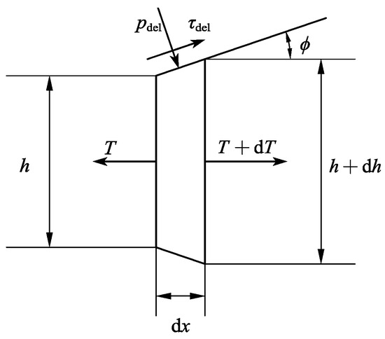
Figure 5.
Schematic diagram of force on the unit body in the deformation zone.
In the equation, T is the horizontal force.
where .
In a similar way, the stress and distribution of the entrance side can be determined. Based on the stress distribution on the entrance and delivery sides, the vertical and horizontal components of the rolling force and rolling moment can be calculated, respectively.
3.2. Multi-System Coupling Dynamics Model
Based on the above dynamic rolling process model, the mechatronic hydraulic coupling system model of the rolling mill is further established. The hydraulic system, as shown in Figure 6, includes the position feedback and rolling force feedback control of the system, with the strip outlet thickness as the final control target. When the system position is specified, the PI controller, the servo valve amplifier and the servo valve are used to control the rolling force. The displacement of the roller system is controlled by the flow into the hydraulic cylinder and the actual displacement is detected by the magnetic ruler in the hydraulic cylinder and transmitted to the input position, forming a closed-loop position control system. In addition, in the vertical system of the rolling mill, there is a way to measure the rolling force and compensate for the elastic deformation of the rolling mill by a certain proportion, so as to indirectly control the thickness of the strip. In this way, the feedback adjustment of the roll gap is realized by the natural stiffness K of the rolling mill, the variable stiffness coefficient αmmc and the equivalent stiffness ks of the strip.
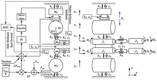
Figure 6.
Schematic of multi-system coupling dynamics model.
Servo valve dynamics equation:
Continuity equation:
Hydraulic cylinder balance equation:
Dynamic stiffness compensation equation:
where ΔSmmc represents the amount of roll gap adjustment required to compensate for rolling force fluctuations and K represents the natural stiffness of the rolling mill.
By combining the above control equations and the dynamic rolling process model, the coupling dynamic model of the rolling mill is created. The parameters in the equation are shown in Table 1.
where

Table 1.
Structural parameters of the rolling mill.
3.3. Model Verification
Since the industrial site has the conditions for measuring the rolling force and vertical stiffness of the rolling mill, the model calculation results of these two values are compared with the field-measured values to verify the accuracy of the model, and the results are shown in Table 2. It can be seen that the vertical stiffness of the calculation model of Equation (15) is within the design stiffness range of the rolling mill, and the difference between the calculated rolling force and the measured rolling force is within 5%, which indicates the accuracy of the steady-state rolling process.

Table 2.
Rolling process parameters.
3.4. System Modal Analysis
First, the mode of the vertical–horizontal–torsional coupling system of the rolling mill is calculated. The damping has little influence on the natural frequency of the system and the angle between the rollers caused by the roller offset is also small. Therefore, the above conditions can be ignored during system modal analysis. Different rolling materials, specifications and other process parameters lead to variations in the equivalent stiffness of the strip steel, and the rolling force in this model is not linear with the roll gap value. Taking into account the fact that the nonlinear system often contains the properties of its derived linear dynamic system. Therefore, it is assumed that the equivalent elastic–plastic stiffness of the strip is ks = 2.5 × 10⁹ N/m and the equivalent stiffness of the hydraulic cylinder is kh = 2 × 10¹¹ N/m by linearizing the equation. According to the above parameters, the calculation results of the natural frequencies and vibration modes of each order of the rolling mill are shown in Table 3 and Figure 7.

Table 3.
Natural frequency of rolling mill coupling system.

Figure 7.
Principal mode of vertical system: (a) 1st order; (b) 2nd order; (c) 3rd order; (d) 4th order; (e) 5th order.
In Figure 7, horizontal coordinates 1–5 correspond to the m0–m4, respectively. Zero and 6 are fixed constraints on the upper and lower ends. The results show that the second-order natural frequency of the vertical system of the model is essentially the same as the vibration frequency detected in the field, and the mode is the relative vibration of the upper and lower roller systems. In order to further investigate the influence of parameters on the natural frequency of each order, the parameter sensitivity analysis of the natural frequency is carried out. The sensitivity can be calculated through the free vibration equation of the system, and the influence of damping on the natural frequency is ignored, which is expressed as:
M and K are the mass and stiffness matrices, respectively. Equation (17) can be transformed into:
Take the partial derivative of pi on both sides of the Equation (18).
Multiply both sides of this equation by {}T.
Transpose both sides of Equation (18).
Due to the symmetric properties of the stiffness matrix and mass matrix,
Equation (20) can be simplified as:
where
The sensitivity can be calculated as follows:
where fi is the i-th natural frequency, {} is the normal mode matrix, corresponding to the modes of order 1–5 in Figure 7 and pj refers to a structural parameter.
The natural frequency sensitivity results are shown in Figure 8.

Figure 8.
Natural frequency sensitivity of each order.
The results show that, firstly, the mass parameters of the system have a greater influence on the higher-order natural frequency, while the low-order natural frequency is more sensitive to the stiffness parameters. Secondly, the sensitivity of the natural frequency to various parameters depends on the vibration mode, and the parameters corresponding to the parts with a large deformation in the vibration mode have a greater influence on the natural frequency of the system. For example, the vibration mode corresponding to the second-order natural frequency of the system is symmetrical to the roll gap. The calculation results show that the stiffness parameter ks between the roll gaps has the greatest influence on the natural frequency of this order. This also explains the phenomenon that the vibration frequency of the mill is different when the rolling material is different.
3.5. Study on the Vibration Influence Law
3.5.1. Vibration Laws of the Rolling Mill with Different Thickness Fluctuation Forms
The billet produced by a continuous casting process is often used as raw material in the continuous rolling process. Due to the role of the vibrating crystallizer in continuous casting, the thickness of the billet changes periodically. As shown in Figure 9, after rough rolling and phosphorus removal process in the hot rolling process, the thickness fluctuation amplitude is greatly reduced, usually less than 50 μm, but there is still a periodic change rule. Different forms of thickness fluctuations lead to different forms of vibration after entering the finishing rolling group. Under ideal conditions, the thickness fluctuation patterns of the sinusoidal and additional skewness are taken as an example, and the vibration during the rolling process is studied with the above coupling model in Section 3.2.

Figure 9.
The thickness of different forms of inlet fluctuates.
The vibration between the roll gaps directly affects the thickness deviation of the strip, which is the most important Therefore, the vertical vibration velocity , horizontal vibration velocity and torsional vibration angular velocity of the work roll are taken as indicators to analyze the vibration state of the rolling mill, corresponding to the first, second and third rows in Figure 10, respectively. It is assumed that the inlet thickness fluctuation frequency is 10 Hz and the amplitude is 0.02 mm. The calculation results are shown in Figure 10. After rolling, the vibration of the rolling mill is basically sinusoidal due to the sinusoidal thickness fluctuation, and the non-sinusoidal form of additional skewness fluctuation leads to rich harmonic components in the vibration of the rolling mill. The 60 Hz in vertical vibration spectrum, 20 Hz in horizontal vibration spectrum and 10 Hz in torsional vibration spectrum are all significant. Obviously, the latter form of thickness fluctuation can easily stimulate the natural frequency of each system of the rolling mill.
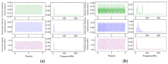
Figure 10.
Vibration characteristics of the rolling mill under different inlet thickness fluctuation patterns: (a) sinusoidal form; (b) non-sinusoidal form of additional skewness.
3.5.2. The Influence of αoff on Vibration
The system dynamics equation shows that the angle αoff created by the work roll offset leads to the coupling relationship on the left side of Equation (14). In the actual production process, the value is usually less than 2°. As the value increases, the coupling strength between the vertical and horizontal structures increases. When the inlet thickness h0 = 22 + 0.02sin(20πt), the vibration characteristics of the rolling mill are examined at different angles, as shown in Figure 11.
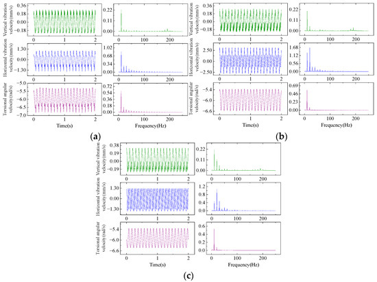
Figure 11.
Vibration characteristics of rolling mill under different roll system offset angles: (a) αoff = 0.005 rad; (b) αoff = 0.01 rad; (c) αoff = 0.015 rad.
The calculation results show that the system response changes from a single frequency output to a higher harmonic output as the inlet thickness varies periodically with sinusoidal regularity and the angle αoff increases. This feature is more obvious in the vertical and horizontal vibration results, and the ratio of the harmonic amplitude to the fundamental frequency amplitude increases with increasing angle. In other words, by increasing this angle, the coupling between the vertical, horizontal and torsion systems is enhanced, so that the system can obtain a response containing rich harmonic frequency components even with a single frequency excitation. This is unfavorable to the mill, as the parameter αoff increases, the low-frequency external excitation cannot only excite the resonance of the torsional system but also excite the resonance of the vertical and horizontal systems.
3.5.3. The Influence of Control Parameters αmmc on Vibration
The closed-loop control process of the roll gap in the rolling mill hydraulic system affects the dynamic characteristics of the system. When the difference between the actual and the reference value of the roll gap is detected in the form of rolling force feedback, the system compensates for the value of the roll gap by adjusting the displacement of the hydraulic cylinder. When the compensation coefficient αmmc = 1, the deviation in the roll gap caused by external disturbances is fully compensated. When the compensation coefficient αmmc = 0, the roll gap change caused by external disturbances is not compensated at all, and usually the value is set between 0.6 ~ 0.9.
The result is shown in Figure 12. Under the same entry conditions, the equivalent stiffness of the strip between the roll gap decreases as the exit thickness decreases, so as the compensation coefficient increases, the exit thickness of the strip becomes smaller and the equivalent stiffness of the strip decreases. Meanwhile, the above sensitivity calculation results in Section 3.4 show that the equivalent stiffness of the strip has the greatest influence on the second-order vibration mode, so increasing the αmmc will lead to a decrease in the second-order natural frequency of the rolling mill, as shown in Figure 12a. Reducing the parameter αmmc can also reduce the peak response of the system and thus reduce the mill vibration at the resonance frequency, as shown in Figure 12b.

Figure 12.
Influence of αmmc on natural frequency and amplitude-frequency of the vertical system: (a) influence of αmmc on the second natural frequency; (b) influence of αmmc on amplitude-frequency characteristic.
4. Conclusions
In this work, the vibration of the rolling mill is monitored and analyzed, and it is found that the dominant vibration frequency of F2 is 10–20 Hz at the beginning. With the rolling process, the harmonic amplitude in the range of 40–60 Hz increases and the vibration increases. Based on this phenomenon, a dynamic model of the non-uniform dynamic rolling process, rolling mill structure and multi-system coupling of the control process is established, and system modal and natural frequency sensitivity analysis is carried out. It is considered that the equivalent stiffness of the strip between the roll gap has the greatest influence on the relative vibration mode of the roll system.
The vibration of the rolling mill excited by a strip with different inlet thickness fluctuation forms is analyzed. It is considered that the periodic change of the inlet thickness under additional skewness can excite the natural frequencies of the vertical, horizontal and torsional systems of the rolling mill.
Due to the structure of the rolling mill, there is an offset between the work roll and the support roll in the vertical direction. The calculation results show that the angle can cause the rolling mill vibration to produce harmonics under the excitation of the inlet thickness fluctuation of a single frequency, and the harmonic components show an increasing trend with increasing angle.
Changing the parameter αmmc in the control system leads to a change in the natural frequency of the coupling system. With the increase of αmmc, the compensation of the roll gap increases, the outlet thickness decreases, the second-order natural frequency of the vertical system decreases and the response peak increases.
Author Contributions
Conceptualization, Y.L.; methodology, Y.L. and X.Y.; software, Y.L.; validation, Y.L., S.W. and X.W.; formal analysis, S.W.; investigation, X.W. and Y.L.; data curation, X.W. and Y.L.; writing—original draft preparation, Y.L.; writing—review and editing, Y.L., X.W. and S.W.; visualization, Y.L.; supervision, Y.L. and X.Y.; project administration, S.W. and X.Y. All authors have read and agreed to the published version of the manuscript.
Funding
This research did not receive any specific grant from funding agencies in the public, commercial or not-for-profit sectors.
Data Availability Statement
The data used to support the findings of this study are available from the corresponding author upon request.
Conflicts of Interest
The authors declare no conflicts of interest.
Nomenclature
| F2 | The second finishing mill |
| Ap | Effective area of hydraulic cylinder piston |
| B | Strip width |
| ci | Equivalent damping |
| Cd | Flow coefficient |
| Ctp | Leakage coefficient |
| fi | Natural frequency of order i |
| fx | Horizontal component of rolling force |
| fy | Vertical component of rolling force |
| Fh | Hydraulic cylinder force |
| h | Thickness of the strip at x distance from the exit of the deformation zone |
| J2dev | The second invariant of stress eccentricity |
| k | The yield limit of the strip |
| ki | Equivalent stiffness |
| mi | Equivalent mass |
| M | Rolling torque |
| pdel | The normal stress of the strip surface |
| ps | Charge oil pressure |
| pL | Loading pressure |
| pt | Back pressure |
| R | Work roll radius |
| ΔSmmc | Roll gap compensation value |
| T | The horizontal force of the unit body |
| W | Area gradient |
| xv | Servo valve spool displacement |
| αoff | Roll offset angle |
| αmmc | Dynamic modulus compensation coefficient |
| βe | Hydraulic oil elastic modulus |
| ρ | Hydraulic oil density |
| σxx | The stress components in x direction |
| σinxx | The stress components in x direction of the strip interior |
| σs | Tensile yield strength |
| τs | Shear yield strength |
| τdel | The tangential stress of the strip surface |
References
- Yarita, I.; Furukawa, K.; Seino, Y.; Takimoto, T.; Nakazato, Y.; Nakagawa, K. An analysis of chattering in cold rolling for ultrathin gauge steel strip. Trans. Iron Steel Inst. Jpn. 1978, 18, 1–10. [Google Scholar] [CrossRef]
- Tlusty, J.; Chandra, G.; Critchley, S.; Paton, D. Chatter in Cold Rolling. CIRP Ann. 1982, 31, 195–199. [Google Scholar] [CrossRef]
- Yun, I.S.; Ehmann, K.F.; Wilson, W.R.D. Chatter in the Strip Rolling Process, Part 2: Dynamic Rolling Experiments. J. Manuf. Sci. Eng.-Trans. ASME 1998, 120, 337–342. [Google Scholar] [CrossRef]
- Yun, I.S.; Ehmann, K.F.; Wilson, W.R.D. Chatter in the Strip Rolling Process, Part 3: Chatter Model. J. Manuf. Sci. Eng.-Trans. ASME 1998, 120, 343–348. [Google Scholar] [CrossRef]
- Yun, I.S.; Wilson, W.R.D.; Ehmann, K.F. Chatter in the Strip Rolling Process, Part 1: Dynamic Model of Rolling. J. Manuf. Sci. Eng.-Trans. ASME 1998, 120, 330–336. [Google Scholar] [CrossRef]
- Gao, Z.Y.; Liu, Y.; Zhang, Q.D.; Liao, M.L.; Tian, B. Chatter model with structure-process-control coupled and stability analyses in the cold rolling system. Mech. Syst. Signal Proc. 2020, 140, 106692. [Google Scholar] [CrossRef]
- Heidari, A.; Forouzan, M.R. Optimization of cold rolling process parameters in order to increasing rolling speed limited by chatter vibrations. J. Adv. Res. 2013, 4, 27–34. [Google Scholar] [CrossRef] [PubMed]
- Zheng, Y.J.; Xie, Z.H.; Li, Y.; Shen, G.X.; Liu, H.M. Spatial vibration of rolling mills. J. Mater. Process. Technol. 2013, 213, 581–588. [Google Scholar] [CrossRef]
- Wang, L.D.; Yan, X.Q.; Jia, X.D.; Wang, X.L. Dynamic Amplitude-Frequency Characteristics of Vertical–Torsional Coupling System with Harmonic Response in Hot Tandem Mill. Electronics 2022, 11, 3031. [Google Scholar] [CrossRef]
- Jia, X.D.; Wang, S.; Yan, X.Q.; Wang, L.D.; Wang, H.P. Research on Dynamic Response of Cold Rolling Mill with Dynamic Stiffness Compensation. Electronics 2023, 12, 599. [Google Scholar] [CrossRef]
- Cui, J.X.; Peng, Y.; Wang, J. Instability of roll nonlinear system with structural clearance in rolling process. J. Iron Steel Res. Int. 2023, 30, 112–125. [Google Scholar] [CrossRef]
- Peng, R.R.; Zhang, X.Z.; Shi, P. Coupled Vibration Behavior of Hot Rolling Mill Rolls under Multinonlinear Effects. Shock Vib. 2020, 2020, 6104028. [Google Scholar] [CrossRef]
- Liu, Y.J.; Wang, S.; Qi, J.B.; Yan, X.Q. Vibrations of tandem cold rolling mill: Coupled excitation of rolling force and variable stiffness of fault-free back-up roll bearing. J. Iron Steel Res. Int. 2023, 30, 1792–1802. [Google Scholar] [CrossRef]
- Zeng, L.Q.; Zang, Y.; Gao, Z.Y. Hopf Bifurcation Control for Rolling Mill Multiple-Mode-Coupling Vibration Under Nonlinear Friction. J. Vib. Acoust. 2017, 139, 061015. [Google Scholar] [CrossRef]
- Kapil, S.; Eberhard, P.; Dwivedy, S.K. Nonlinear Dynamic Analysis of a Parametrically Excited Cold Rolling Mill. J. Manuf. Sci. Eng. 2014, 136, 041012. [Google Scholar] [CrossRef]
- Hou, D.X.; Peng, R.R.; Liu, H.R. Analysis of Vertical-Horizontal Coupling Vibration Characteristics of Rolling Mill Rolls Based on Strip Dynamic Deformation Process. Shock Vib. 2014, 2014, 543793. [Google Scholar] [CrossRef]
Disclaimer/Publisher’s Note: The statements, opinions and data contained in all publications are solely those of the individual author(s) and contributor(s) and not of MDPI and/or the editor(s). MDPI and/or the editor(s) disclaim responsibility for any injury to people or property resulting from any ideas, methods, instructions or products referred to in the content. |
© 2024 by the authors. Licensee MDPI, Basel, Switzerland. This article is an open access article distributed under the terms and conditions of the Creative Commons Attribution (CC BY) license (https://creativecommons.org/licenses/by/4.0/).