Abstract
In this study, a novel cambered snow removal device is designed to achieve automatic snow removal in large curved areas, such as the south roof of a Chinese solar greenhouse. The theory of structural parameters and shear force is ambiguous. People are not based on the greenhouse structure parameters for the selection of snow removal devices. Therefore, the quantitative relationship between the structure of the greenhouse span and the number of scissor arm-length knots is analysed, and the relationship between the material strength and application distance is determined. This study’s objectives are (1) to establish a theoretical model of scissor arm motion and (2) to analyse the force distribution of the scissor arm using multi-body dynamics. The results show that the scissor arm of a round-arch greenhouse has fewer sections but a larger arm length, whereas the scissor arm of a traditional solar greenhouse has more sections but a smaller arm length. Based on the shear force of the scissor structure, the optimised wall thickness reduces the force of the node by 17%.
1. Introduction
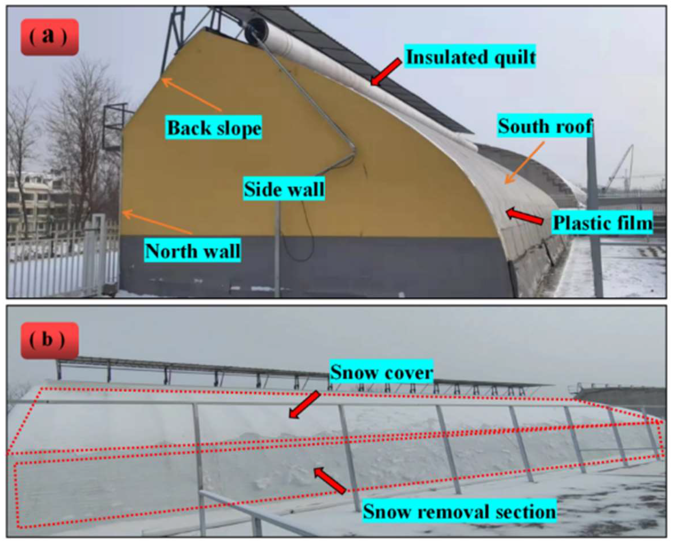
Chinese solar greenhouses (CSGs) contribute significantly to the supply of fruits and vegetables in northern China. However, heavy snowfall during winter in the middle and high latitudes causes snow accumulation in CSGs [1,2,3]. The snow accumulation on the front roof of CSGs results in low crop yield, mechanical damage, or greenhouse collapse [4,5]. The general construction of a CSG is depicted in Figure 1a, which shows the south roof, back slope, back wall, and side walls [6]. As shown in Figure 1b, the south roof is covered with an insulation quilt to maintain the temperature stability inside the CSG during snowfall. However, the differing inclination degrees of the front roof led to the natural shedding of snow at the bottom’s more significant inclination angle and the creation of snow at the top slight inclination angle.

Figure 1.
(a) CSG structure. (b) Schematic diagram of snow accumulation on the south roof insulation.
Owing to the environmental variances and varied crops cultivated in each location, the span of the CSG, the inclination angle of the south roof, and other structural parameters are different. Therefore, the shape of the south roof of a solar greenhouse is irregular. Moreover, the south roof is coated with insulation, which makes installing and maintaining a snow removal device (SRD) difficult. Most farmers still use snow shovels or blowers to remove snow, which incurs high labour costs. Greenhouses often collapse owing to untimely snow removal, causing considerable economic losses. Computer-aided engineering technology is used to simulate the deformation of Chinese solar greenhouse skeletons under wind and snow loads [7,8]. The aforementioned studies provide a theoretical basis for the rational optimisation of the skeleton. An electric-motor-driven rail-type snow shovel is used to remove snow from coloured steel tiles [9]. Researchers have improved robots to clear snow from sloping roofs [10]. Yan and Zhou proposed models for snow drifting on flat and sloping roofs, respectively [11,12]. Electricity is used to heat solar panels to remove snow from tilted solar panels [13,14]. Researchers have developed an early warning mechanism for greenhouse snow loads based on a greenhouse snow collapse model [15]. Projects have been created to solve the problem of snow accumulation in solar greenhouses. The structure of the film winder is changed, and mechanical waves are generated for snow removal [16]. However, this method is only applicable to southern plastic greenhouses and not northern solar greenhouses. In one study, roller brushes were connected in series to a hydraulic pivot arm. The hydraulic arm was connected to a tractor, which was manoeuvred to remove snow from a solarium [17]. However, the device was bulky and could not be automated. Thus, none of the aforementioned SRDs can solve the problem of snow accumulation on the south roof of solar greenhouses.
To solve the problems of a large extent and inconsistent slope of the south roof of CSGs, a structure that can telescope along the front roof of the greenhouse must be designed. The shear structure has a large systolic ratio and has the ability to work in curved areas, and its range of motion can be explained using a mathematics model [18,19]. Researchers have designed foldable shear-type robotic arms to grip heavy objects [20]. Shear structures are also designed for hydraulic lifts, and detailed process parameters can be calculated [21]. Shear structures have also been used in paint robots to extend the travelling space of the arms [22]. The shear structure includes special structures for expansion and contraction. Deformable and compressible shear structures with large compression ratios have also been used in space operations [23]. An SRD utilises a shear mechanism and an articulated structure to achieve telescopic and rotational movements along the front roof of the greenhouse. Force and deformation analyses of static cantilever structures have become common [24]. However, the study of the stress distribution during the motion of shear structures involves only two directions: horizontal and vertical. The structural stresses in complex shear structures during tilting motion are unknown. Therefore, the stresses in shear structures during tilting motion are investigated in this study.
Solid-Works 2018 software was used for modelling [25], and Adams-View 2019 software was used to simulate the dynamics of the scissor extension mechanism [26,27,28], evaluate the shear force at the connection point of the scissor arm, and analyse the effects of the arm length, wall thickness, and extension length on the shear force of the scissor structure during the tilt extension process. The appropriate scissor arm models were determined based on various greenhouse types and spans under the concept of maintaining structural safety. Finally, the shear force change in each structural unit connection point of the scissors was determined during movement. An optimisation technique for scissor arm wall thickness was also presented.
2. Materials and Methods
2.1. Model and Working Principle
Figure 2 depicts the overall structure of the scissor arm. It consists of a track trolley, a standard track, an electric pusher, a pusher swing arm, an articulated assembly, a drive motor, a scissor arm, and a snow blade. The working principle of the SRD is shown in Figure 3. The standard track is connected to the solar greenhouse skeleton, and the track trolley moves laterally along the standard track at the top of the solar greenhouse. The scissor arm is connected to the track trolley through the rotary hinge ear, the front end of the scissor arm is connected to the snow blade, and the operating systems are coordinated to clean the snow on the south roof of the CSG.
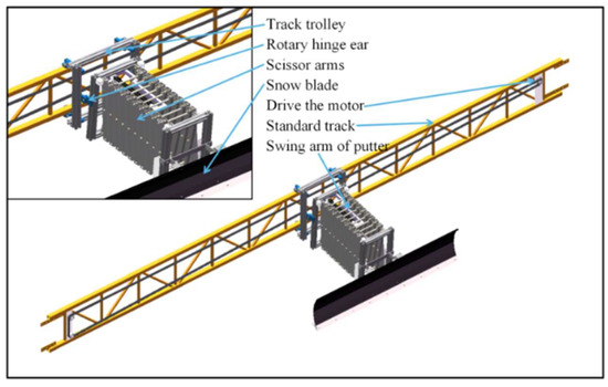
Figure 2.
Schematic of the SRD structure.
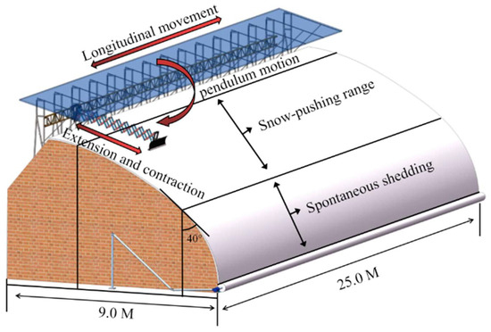
Figure 3.
Schematic diagram of the working principle of the SRD.
A motion sketch of the SRD was created to illustrate its range of activity, as shown in Figure 4. Here, the black line box represents the track trolley, which can move along the east–west track. The blue line box represents the scissor structure, which can contract or extend. These two structures are connected by a hinge that can be rotated up and down. A Cartesian coordinate system is created using the centre point of the hinge as the origin. South is the positive direction of the z-axis. Vertical upwards is the positive direction of the y-axis. East is the positive direction of the z-axis. Take point E as the research object and analyse its activity range in 3-dimensional space, E (x, y, z). α is the extension angle of the scissor structure controlled by the pusher ①; β is the dip angle of the scissor structure controlled by the pusher ②; and is the length of the hinge l1. is the length of the arm l. N is the number of scissor units. The range of activity of point E in the x-direction is shown in Equation (4). The range of activity in the y-direction is shown in Equation (5). The range of activity in the z-direction is equivalent to the length of track laying, 0 M < z < 25 M.
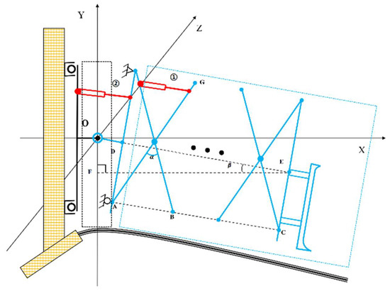
Figure 4.
Simplified diagram of an assembled SRD with n scissor units.
2.2. Transmission Mechanism
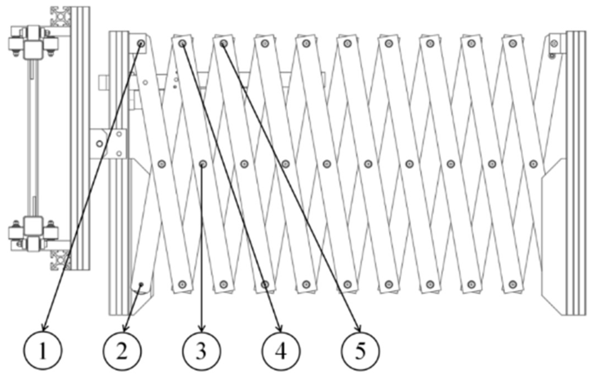
As shown in Figure 5, point 1 is the electric actuator lower swing arm installation position. Four upper swing arm installation positions are present, of which point 2 has stress concentration when the scissor arm tightens. Point 3 is extremely long owing to the upper swing arm, meaning that the scissor arm cannot be drawn. At point 5, the length of the actuator cannot meet the requirements of the maximum extension angle. Thus, point 4 is the optimal installation position.

Figure 5.
Telescopic mechanism.
During the extension of the scissor arm, the electric actuator swing arm moves higher, and the force analysis reveals that the ideal installation location is an extension angle of 120°. As illustrated in Figure 6, the lower swing arm rises when the scissor arm is extended. At an angle () of 120°, the distance of is 0. The mathematical relationship is shown in Equation (6), where = = 4 cm, the value of angle is 0°–120°, 0, and the minimum value of the distance, , between the lower swing arm of the linear actuator and the scissor arm connection point is 8 cm.
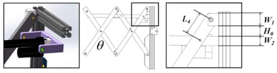
Figure 6.
Push rod lower swing arm installation.
2.3. Range of Snow Accumulation in Solar Greenhouses
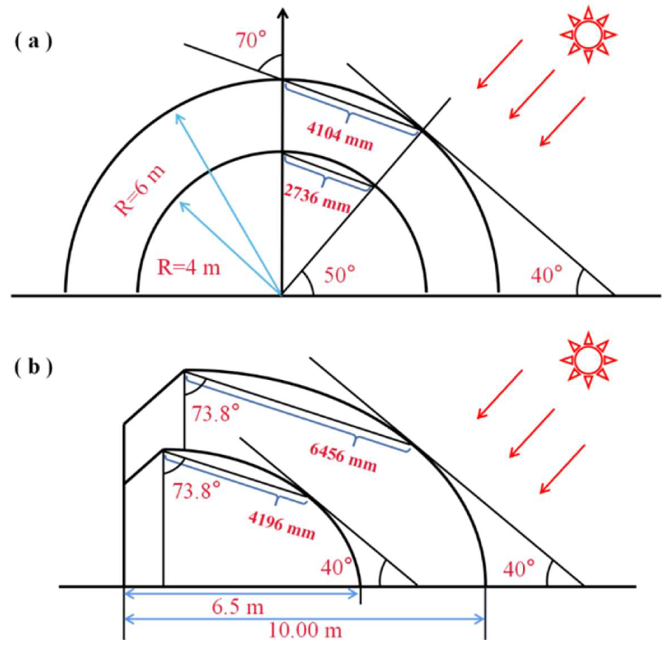
In China, the span of a conventional CSG in the area of 34°–46° N is 6.5–10.0 m, the top height is 3.9–6.6 m, and the inclination angle of the south roof of the greenhouse is 32°–43°. The space inside a round vaulted solar greenhouse (RVSG) is larger, with good lighting and relatively better thermal insulation. Therefore, the span is larger than that of a conventional CSG. Typically, the span of RVSGs is 8.0–12.0 m. Several studies have indicated that when the inclination angle of the south roof of the greenhouse is larger than 30°–40° [29], the snow on the south roof slides down naturally owing to the action of gravity. As shown in Figure 7, the snow accumulation ranges from a roof inclination angle of 40° to the top of the greenhouse is 2736–4104 mm for an RVSG with a span of 8.0–12.0 m. The snow accumulation ranges from a roof inclination angle of 40° to the top of the greenhouse is 4196–6456 mm for a typical CSG with a span of 6.5–10.0 m. The snow accumulation part of both greenhouses can be considered as a sloping surface with an inclination of 70°.

Figure 7.
(a) Range of snow accumulation on the south roof of an RVSG with an 8.0–12.0 m span. (b) Range of snow accumulation on the south roof of a conventional CSG with a 6.5–10.0 m span.
2.4. Relation between Section Number and Span
The difference between the conventional CSG and RVSG in snow clearing is evident primarily in the snow range owing to the difference in the cross-sectional structure. The snow removal range of the RVSG is significantly lower than that of the conventional CSG for the same span. The snow removal range, , of the two types of greenhouses is 2.5–6.5 m. The elements connected to the extension of the telescopic mechanism are related to the number of scissor arm sections, , length of the scissor arm, , and extension angle, , as displayed in Figure 8. The correlation is shown in Equation (7).
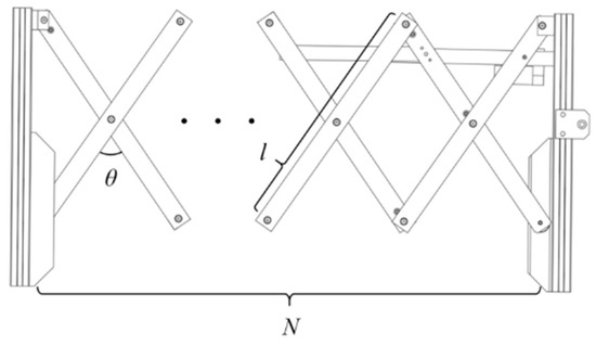
Figure 8.
Scissor arm structure.
2.5. Greenhouse South Roof Snow Force Analysis
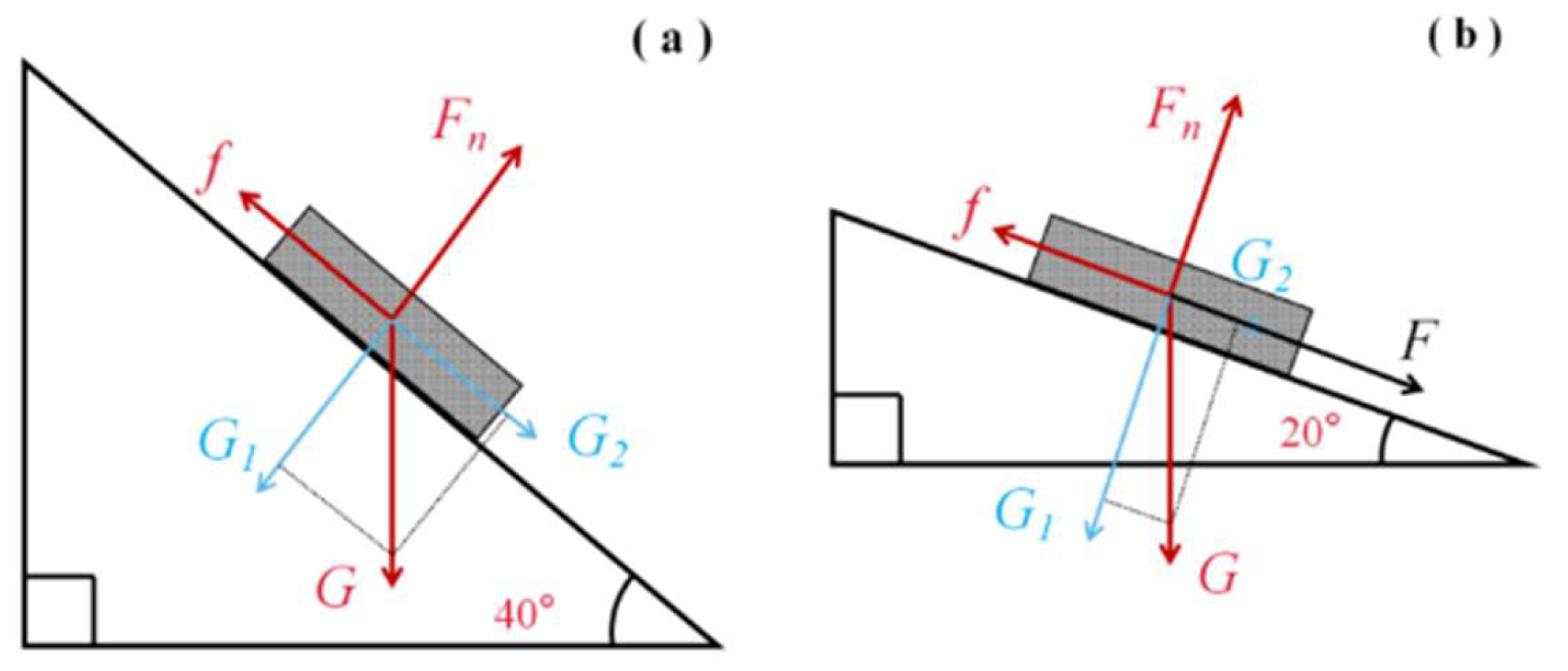
The angle between the south roof of the conventional CSG and RVSG and the horizontal plane is 20°. Its force analysis is presented in Figure 9. As the snow naturally glides down when the greenhouse south roof inclination is below 40°, the frictional force, , of the snow is regarded as equal to the component force, , of the snow gravity down along the roof at this time. The force balance equations are expressed in the direction along the inclined plane and in the direction of the vertically inclined plane. The simplification provides the thrust force, , and friction factor, .
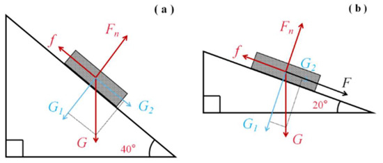
Figure 9.
(a) Overall force analysis of snow accumulation at a 40° dip angle. (b) Overall force analysis of snow accumulation at a 20° dip angle.
2.6. Dynamics Simulation
The scissor arm model is drawn using Solid-Works software and saved in a para-solid format. Open Adams-View software is used to import the model. First, the imported model is subjected to Boolean operations to combine the parts. Second, the material properties of each part are renamed and defined. Then, the constraints, contacts, and dynamics are applied. Finally, the solver is set up, and a simulation is performed. The constraints of the structure are set as shown in Figure 10. The driving function employed is the time–displacement function step(time, 0, 0, 10, c) + step(time, 10, 0, 20, −c) + step(time, 20, 0, 30, c) + step(time, 30, 0, 40, −c), where c denotes the displacement. The value of c is calculated using Equation (14), where b is the width of the aluminium profile (b = 38 mm).
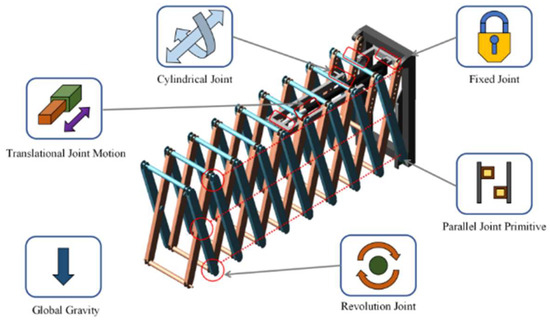
Figure 10.
Adams multi-body dynamics simulation model constraint settings.
3. Results and Discussion
3.1. Relationship between Span, Snow Accumulation, and Stress
The relationship between the snow accumulation range and the number of scissor arm sections required for the two types of solar greenhouses is presented in Table 1.

Table 1.
Correspondence between the span of different types of greenhouses, range of snow accumulation, length of the scissor arm, and number of scissor arm sections.
Several studies have indicated that the thicker the snow, the denser it is under gravity. Thus, the value of is considered as the maximum density of snow [30]; = 0.64 g/cm3. The values of , , and are inserted into the Formulas (10)–(13) to obtain the thrust force, . If = 0.75 m, is considered as 5 cm, 10 cm, and 15 cm for each type of greenhouse. The relationship between the range of snow removal and the required thrust force, , for snow removal of different spans is shown in Figure 11. The thrust required for snow removal in both types of greenhouses should be mainly related to the greenhouse span. However, with the increase in span, the thrust required for snow removal in the conventional CSG is higher than that in the RVSG.
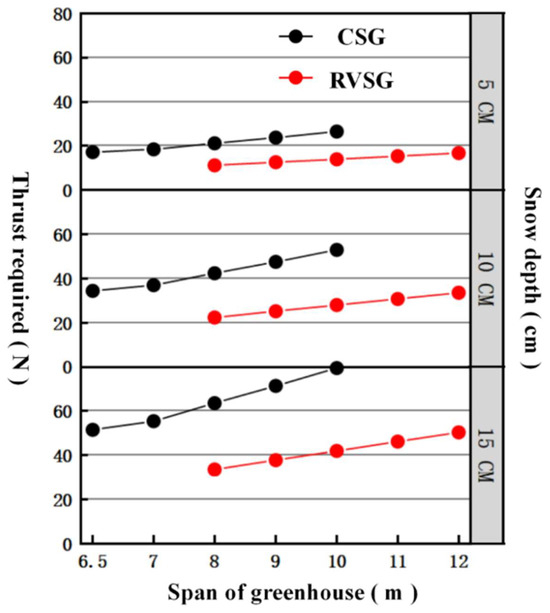
Figure 11.
Thrust required to clear the snow when the snow depth on the south roof is 5 cm, 10 cm, and 15 cm for an RVSG with an 8.0–12.0 m span and a conventional CSG with a 6.5–10.0 m span.
3.2. Dynamics Analysis
The scissor arm is made of AL6010 with a material strength of 210 MPa. The diameter of the shaft is 6 mm, and the material is structural steel Q325 with a strength of 300 MPa. According to Equations (15)–(17), the calculated scissor arm thickness is divided into 1, 2, 3, 4, and 5 mm when the maximum shear resistance of the scissor arm is 1260, 2520, 3780, 5040, and 6300 N, respectively. The maximum shear resistance of the shaft is 4241 N.
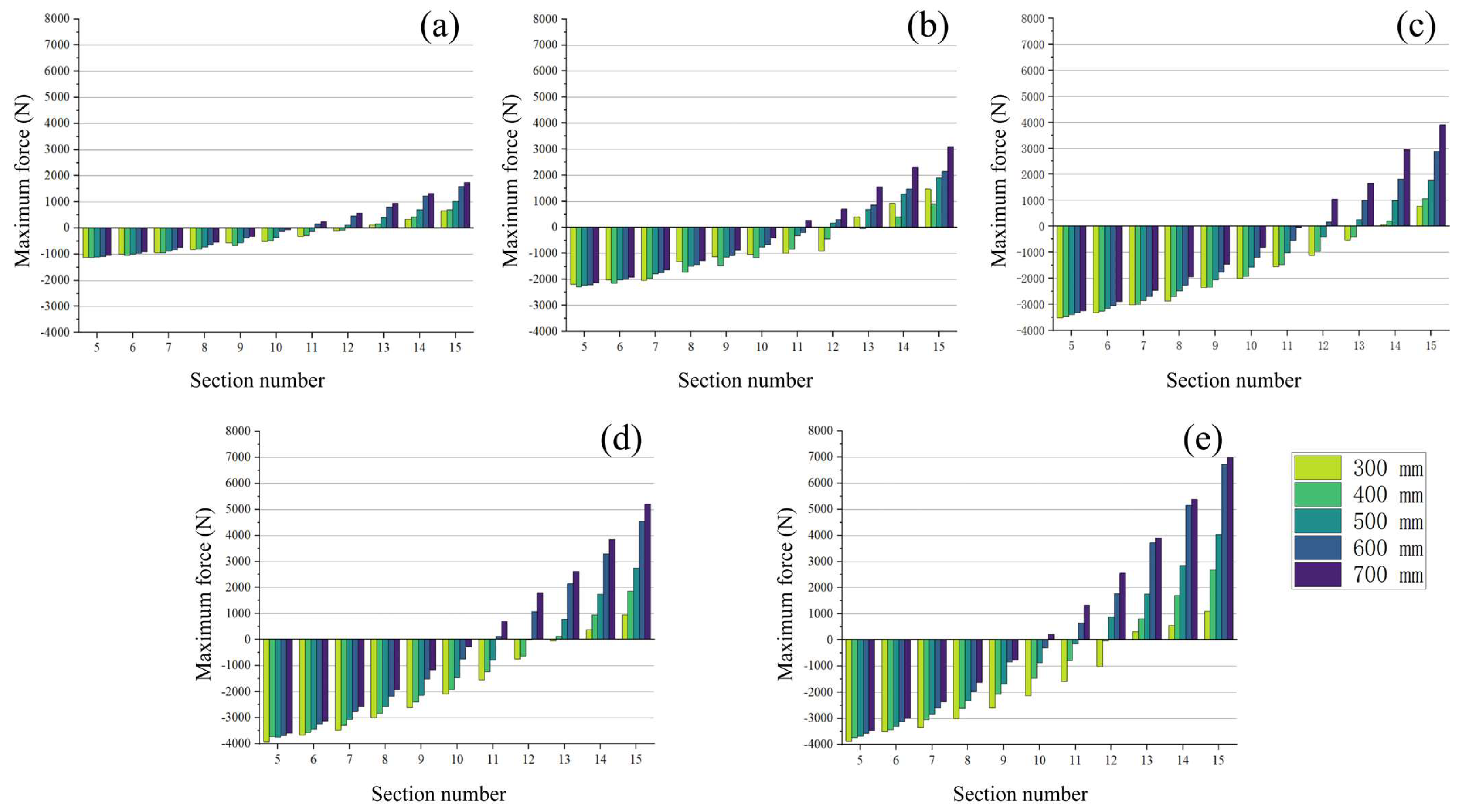
The thicker the scissor arm, the greater the effect of gravity on the mass. The structural strength of the scissor arm connection is less than the structural strength of the shaft when the thickness of the scissor arm is 1–3 mm. Therefore, the shear forces at the connection point should be less than the maximum shear resistance of the scissor arm. For more than 3 mm, the structural strength of the scissor arm will be greater than the structural strength of the shaft. For thicknesses of 1, 2, and 3 mm, the maximum shear resistance is 1260, 2520, and 3780 N. For thicknesses of 4 and 5 mm, the maximum shear resistance of the shaft is subtracted from the maximum shear resistance of 4241 N. The results in Figure 12 show the nodal shear force minus the maximum shear force obtained from the simulation calculations The results indicate that increasing the wall thickness causes a significant increase in the shear force at the connection point of the scissor arm. In contrast, the number of sections that can be applied increases and then decreases as the material thickness increases within the range of the maximum shear resistance. When the wall thickness is small, the maximum shear resistance of the scissor arm is less than the shear force of the shaft and gradually converges to the shear force of the shaft as the wall thickness increases. The number of applied sections also gradually increases, increasing the wall thickness until the maximum shear resistance of the scissor arm and the shaft reaches its optimal length. After the increase in the wall thickness, the structure is significantly affected by gravity, and the shear force at the connection point of the scissor arm increases. In contrast, the structural strength of the shaft remains unchanged, resulting in a decrease in the number of maximum permissible sections.

Figure 12.
(a–e) Maximum shear force distribution at different scissor arm connection points when the scissor arm thicknesses are 1, 2, 3, 4, and 5 mm, and the extension angle is 120°.
Increasing the scissor arm length increases the extension length of a single section of the scissor arm. However, this makes the whole structure larger and more difficult to install and fix. Therefore, when the application distance is the same, the shortest possible scissor arm is selected. The correspondence between the maximum shear resistance of the node and the number of sections achieved by increasing the length of the scissor arm is shown in Figure 13. As the maximum shear resistance increases with an increase in the scissor arm length, the number of sections that can be applied decreases gradually.
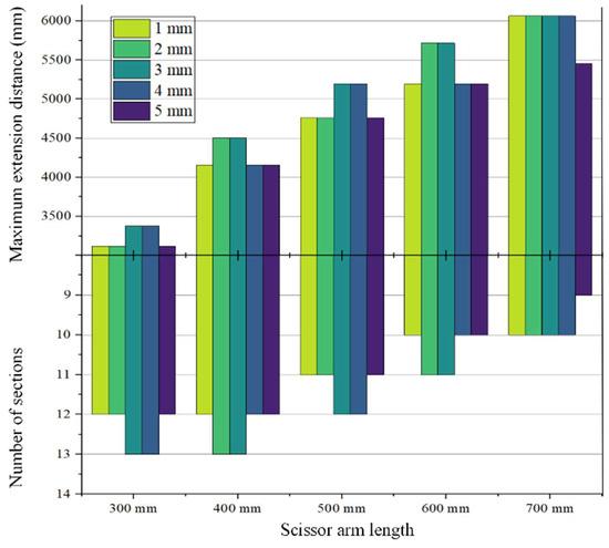
Figure 13.
Distribution of the maximum extension distance and the number of sections in the range of maximum shear resistance of the material for different thicknesses and lengths of the scissor arm with an extension angle of 120°.
As shown in Table 2, the effect of increasing the arm length on the actual application length of the scissor arm is greater than that of increasing the wall thickness. However, the greenhouse is covered with insulation at the top. Moreover, the upper part is equipped with partial energy storage facilities. Thus, a smaller total volume of the overall SRD is better. If the scissor arm parameters satisfy the snow removal requirements, the shorter arm length is chosen as the first choice. Furthermore, to reduce the weight of the device and save material, the scissor arm thickness should be 1–3 mm. However, the lower structural strength should be avoided considering the gravity of the snow removal operating end, snow removal thrust, and joint friction. Therefore, the most suitable scissor wall thickness should be 2 mm or 3 mm.
Table 2.
Relationship between range, number, and force for different scissor arm lengths and thicknesses.
The correspondence between the span and snow accumulation range of the two types of greenhouses and the actual permissible length of the scissor arms is shown in Table 3. The applicable scissor arm lengths are 300 mm for an RVSG span of 8.0–9.0 m, 400 mm for a span of 10.0–12.0 m, and 500 mm for a span of 6.5–7.0 m in a conventional CSG and 600 mm for a span of 8.0 m and 700 mm for a span of 9.0 m. As this study was conducted exclusively to evaluate the impacts of various parameters of the scissor arms on structural stresses, only the scissor arms were chosen. Because only the influence of the scissor arm parameters on the structural stresses is investigated, only the commonly used parameters are selected for this study. Moreover, the best scissor arm model for snow removal on a larger span and more extensive area of the arc can be calculated using this method.
Table 3.
Snow removal range and the most suitable scissor arm type corresponding to 8.0–12.0 m for an RVSG and 6.5–10.0 m for a conventional CSG.
3.3. Scissor Arm Thickness Optimisation
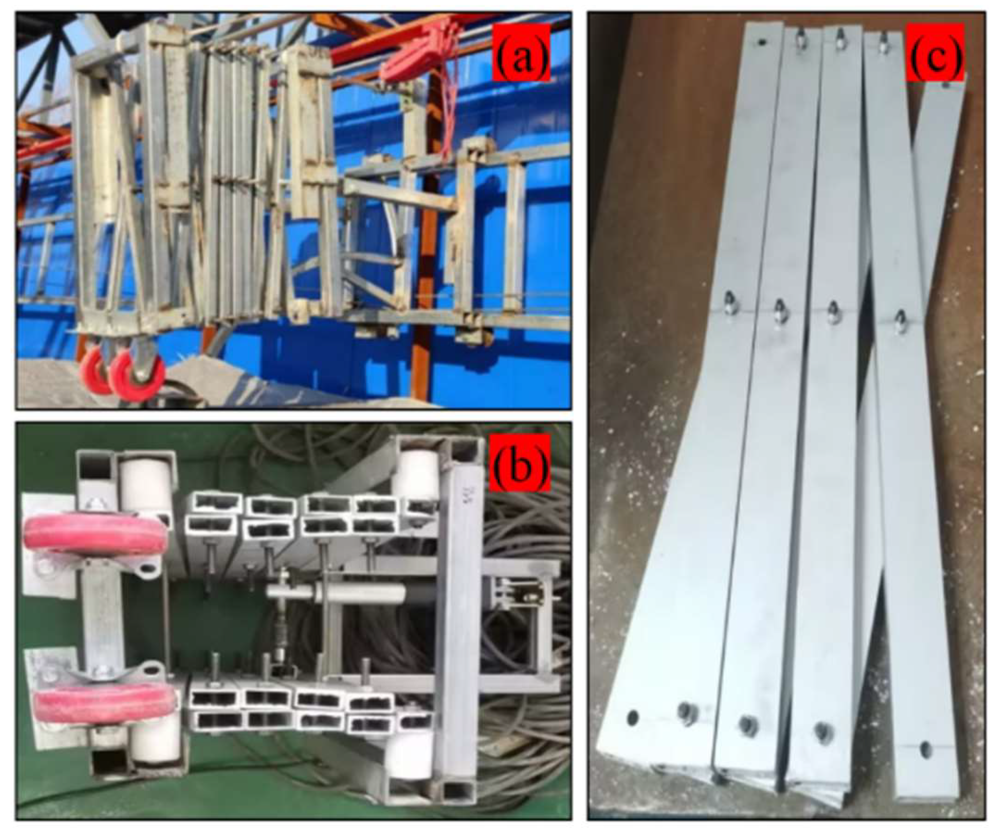
As shown in Figure 14a,b, the test prototype operation reveals that the snow removal operation end of the SRD decreases significantly after the scissor arm extension and the insulation is cut. Structural stress concentration due to gravity occurs during scissor arm movement. Nevertheless, the structural strength of the scissor arm is inadequate for sustaining these loads, resulting in deformation and wear of the scissor arm at the joints and causing the front end of the SRD to collapse, as shown in Figure 14c.
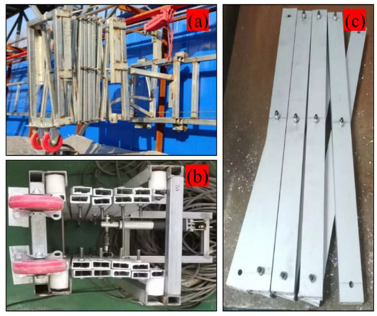
Figure 14.
(a) Prototype running test; the scissor arm is made of a square tube. (b) Second prototype running test; the scissor arm is made of aluminium profile. (c) The scissor arm connection hole is deformed and badly worn.
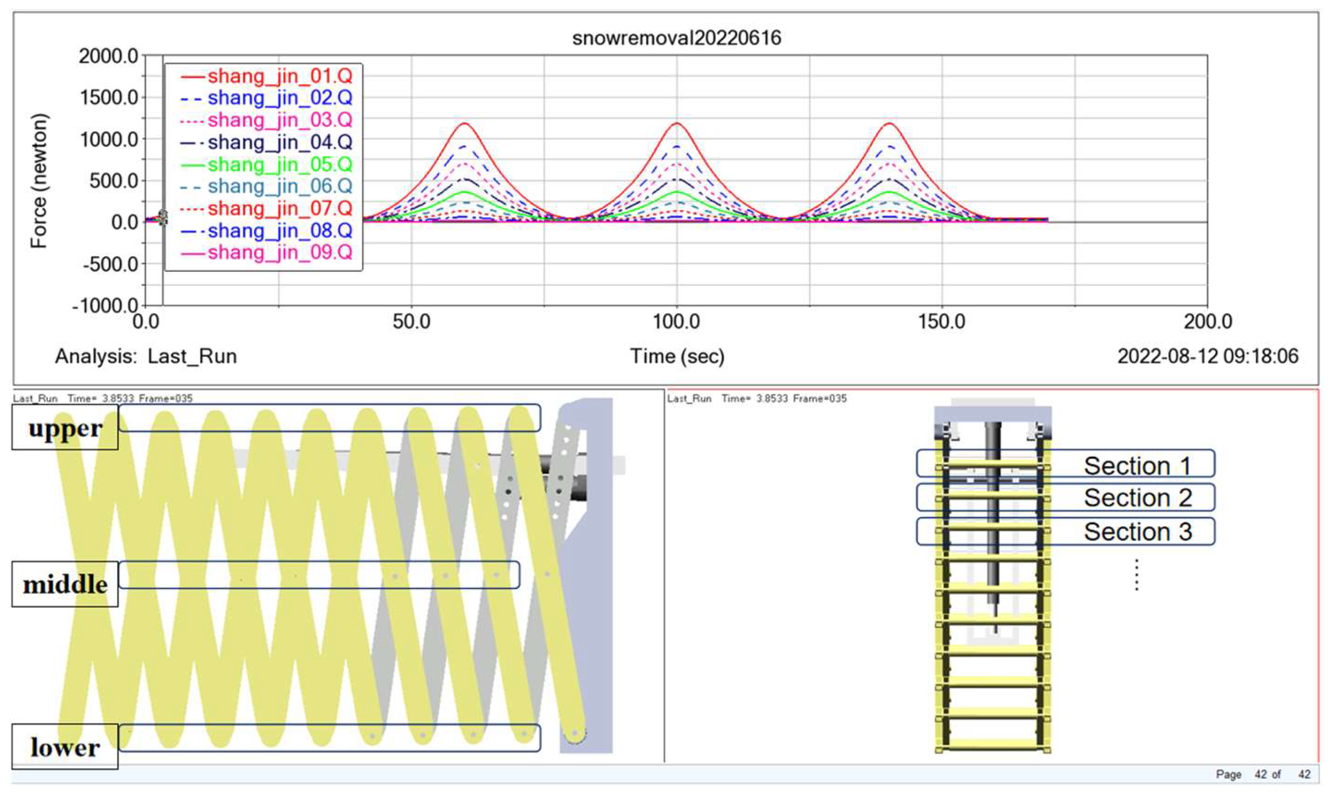
The shear force at the connection point of the horizontally suspended shear structure is influenced by gravity; this is different from the horizontal arrangement with gravity direction and support. The shear force at the connection point exhibits nonlinear changes. In the simulation model shown in Figure 15, a scissor arm with an arm length of 500 mm, a wall thickness of 2 mm, and nine sections is selected as the object of study. The shear force in the upper middle and lower parts of the shear structure is measured during the motion of the shear structure.
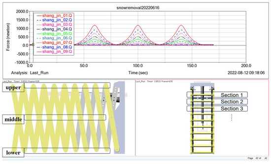
Figure 15.
Post-processing of dynamics simulation results.
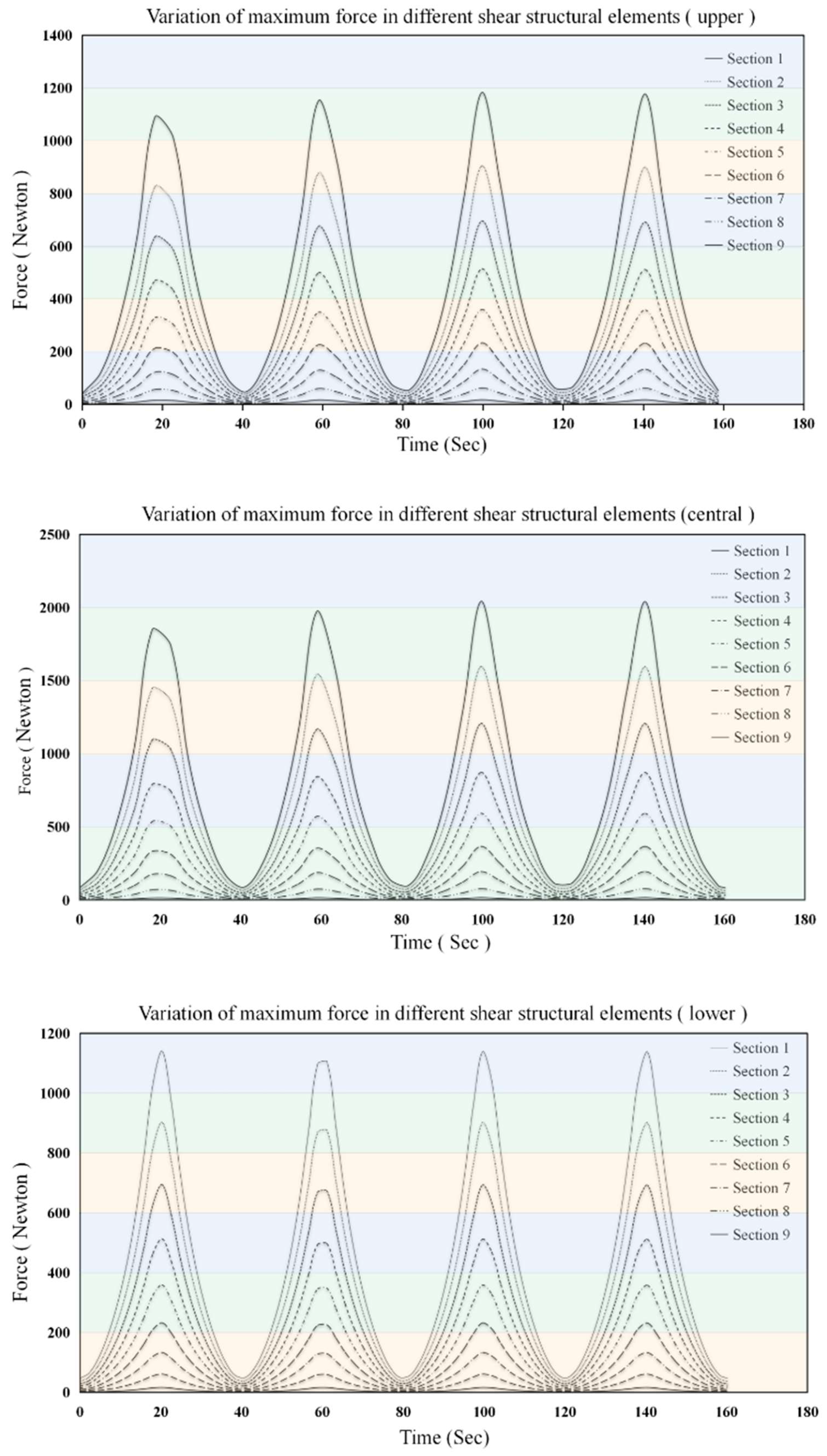
As shown in Figure 16, the shear force at the upper, middle, and lower joints of the shear structure first increases and then decreases during the extension and contraction processes. The shear force in the structure reaches its maximum value at the maximum extension angle. The maximum shear force in the upper, middle, and lower parts of each shear structure unit vary between 41.76–1183.76 N, 84.09–2041.88 N, and 47.54–1141.37 N, respectively.
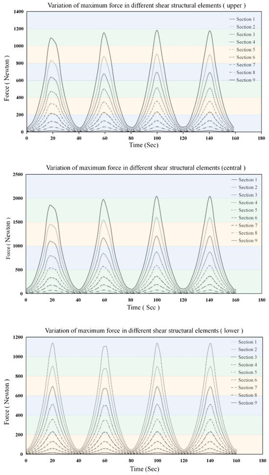
Figure 16.
Shear force of the scissor arm.
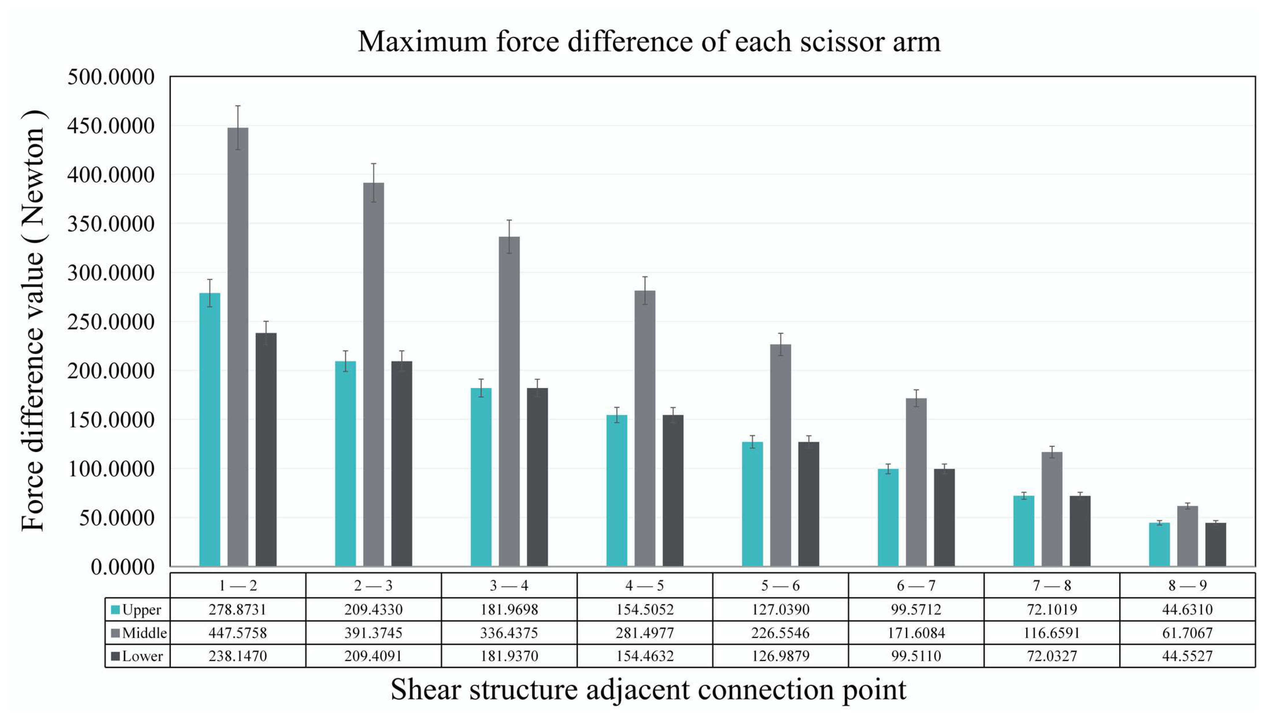
The differences between the maximum shear force of adjacent shear structural units are shown in Figure 17. The reduction in the maximum shear force of the adjacent shear structures gradually decreases. The shear force in the upper and lower joints changes almost identically. The shear force change at the connection points of the horizontally suspended shear structure does not vary linearly with the number of shear structural units.
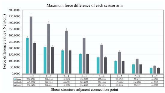
Figure 17.
Difference in the maximum shear force at the connection point of adjacent shear structures.
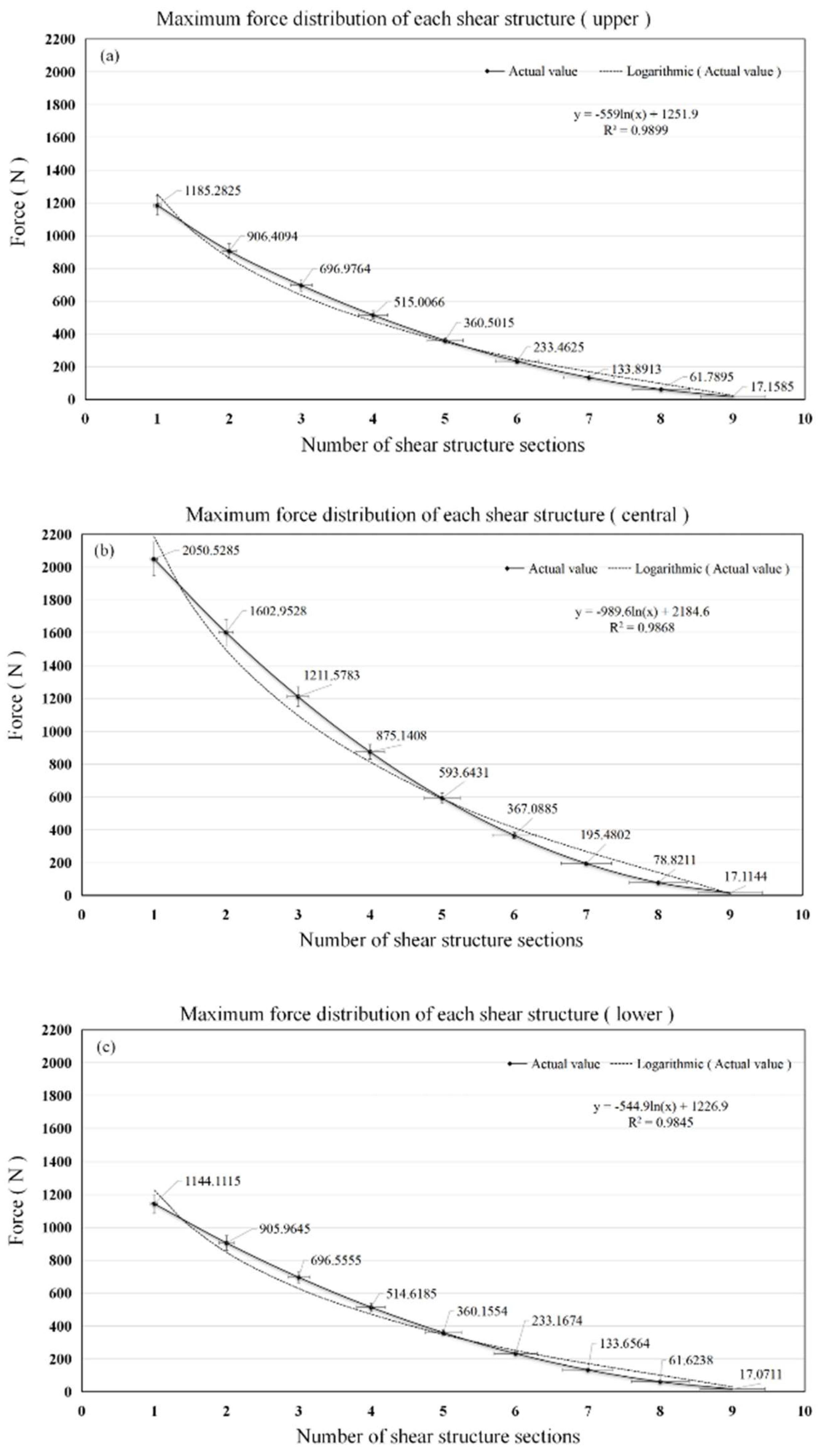
To determine the relationship between the number of scissor arm sections and the maximum shear force, scissor arm shear force is examined by performing functional fitting. As shown in Figure 18, the highest degree of fit is logarithmic, and the results of the logarithmic function fit reveal that the function between the upper connection point of the scissor arm and the maximum shear force is y = −559ln(x) + 1251.9, with a variance of R2 = 0.9899. The functional relationship between the connection point in the middle of the scissor arm and the maximum shear force is y = −989.6ln(x) + 2184.6, with a variance of R2 = 0.9868. The functional relationship between the lower connection point of the scissor arm and the maximum shear force is y = −544.9ln(x) + 1226.9, with a variance of R2 = 0.9845. Therefore, the number of scissor arm sections and their maximum shear force conform to a logarithmic relationship for a shear structure with a horizontal overhanging arrangement.
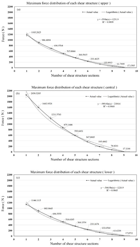
Figure 18.
Scissor arm connection point maximum shear force variation curve. (a) Shear force variation curve at the upper connection point. (b) Shear force variation curve at the central connection point. (c) Shear force variation curve at the lower connection point.
In the overhanging arrangement of the scissor arm under gravity, the shear force difference between different scissor arm wall sections is large, resulting in a partial structural shear force overload and partial structural thickness surplus. To reasonably allocate the material to enhance the structural performance, the maximum shear force of each scissor arm section combined with the sum of each resistance is 480 N under a constant total wall thickness. Subsequently, the wall thickness of each scissor arm section is optimised as per the law of logarithmic variation. The specific optimisation results are listed in Table 4.
Table 4.
Wall thickness optimisation results for each section of the scissor arm.
As shown in Figure 19, the shear force in each section of the optimised scissor arm is reduced. The maximum stresses in the upper, middle, and lower sections of the scissor arm before optimisation are 1173.53 N, 2027.67 N, and 1131.25 N, which are reduced to 953.46 N, 1673.81 N, and 937.25 N, respectively. After the wall thickness is optimised, the reductions are 18.75%, 17.45%, and 17.15%, respectively, suggesting that optimising the wall thickness of the scissor arm can successfully reduce the shear force distribution of the scissor arm.
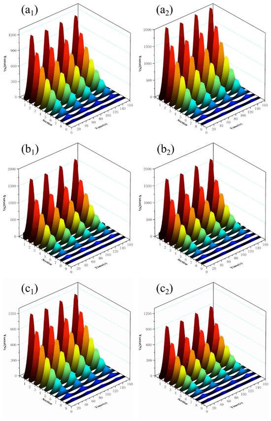
Figure 19.
Comparison chart of wall thickness optimisation results of the shear structure. (a1) Shear force at the upper connection point before optimisation. (a2) Shear force at the upper connection point after optimisation. (b1) Shear force at the middle connection point before optimisation. (b2) Optimised shear force at the central connection point. (c1) Optimisation of shear force at the lower front joint. (c2) Shear force at the lower connection point after optimisation.
4. Conclusions
In this study, an SRD for the south roof of a solar greenhouse was designed, and a mechanical model of the scissor arm was developed. The main contributions of this study are as follows.
- (1)
- The designed SRD can be applied to a large curved area, such as a solar greenhouse; it satisfies the snow removal requirements of a greenhouse, reduces labour intensity, and realises the automatic snow removal function of a greenhouse using telescopic scissor arms, rotating hinge lugs, and transitional rail cars.
- (2)
- Simulation results of scissor arm multi-body dynamics show that increasing the arm length can significantly increase the applied range of the scissor arm but reduce the number of applied knots. Increasing the wall thickness can increase the applied length of the scissor arm. When the thickness increases to a level greater than the strength of the pin roll, the maximum applied length is reduced due to gravity.
- (3)
- The short scissor arms with long knots are used in round-arched solar greenhouses, and the applicable length of scissor arms for greenhouses with a span of 8.0–12.0 m is 300–400 mm. Traditional solar greenhouses utilise long scissor arms with more sections, and the applicable length of scissor arms for greenhouses with a span of 6.5–10.0 m is 500–700 mm.
- (4)
- The wall thickness of the scissor arm is optimised based on the shear force in each section of the scissor arm. Before optimisation, the maximum shear force at the upper, middle, and lower connection points of the scissor arm are 1173.53, 2027.67, and 1131.25 N. After optimisation, the shear force decreases to 953.46, 1673.81, and 937.25 N, with a reduction of 18.75%, 17.45%, and 17.15%, respectively.
Author Contributions
Methodology, X.L.; Software, Y.L. (Yu Liu); Resources, S.G.; Writing—original draft, Z.G.; Writing—review & editing, Y.L. (Yiming Li); Project administration, T.L. All authors have read and agreed to the published version of the manuscript.
Funding
This work was supported by the Northeast Geological S&T Innovation Center of the China Geological Survey [QCJJ2022-26].
Data Availability Statement
Data will be made available upon request.
Acknowledgments
The authors are grateful to the National and Local Joint Engineering Research Center of Northern Horticultural Facilities Design and Application Technology for supporting this project.
Conflicts of Interest
The authors declare that they have no known competing financial interests or personal relationships that could have appeared to influence the work reported in this paper.
Nomenclature
| Symbols | |||
| L4 | Distance between the connection points (cm) | θ | Stretch angle (°) |
| W1 | Width of the articulated assembly (cm) | σ | Yield strength (N·mm−2) |
| W2 | Width of the pusher lower swing arm (cm) | μ | Coefficient of friction |
| H0 | Distance between the articulated body from the lower arm (cm) | Abs1 | Scissor arm shaft force area (mm2) |
| L | Snow removal range (m) | Abs2 | Shaft cross-sectional area (mm2) |
| l | Scissor arm length (mm) | ρ | Density (kg·m3) |
| α | Extension angle (°) | β | Tilt angle (°) |
| N | Number of sections | d | Shaft diameter (mm) |
| a | Width of snow removal (m) | h | Thickness of scissor arm (mm) |
| b | Scissor arm width (mm) | g | Gravitational acceleration (m/s2) |
| c | Length (mm) | m | Quantity (kg) |
| l2 | Hinge length (mm) | ||
References
- Gao, J. Analysis and assessment of the risk of snow and freezing disaster in China. Int. J. Disaster Risk Reduct. 2016, 19, 334–340. [Google Scholar] [CrossRef]
- Yang, Z.-Q.; Zhang, T.-H.; Huang, H.-J.; Zhu, K.; Zhang, B. Meteorological Disaster Risk Evaluation of Solar Greenhouse in North China. Chin. J. Agrometeorol. 2013, 34, 342–349. [Google Scholar] [CrossRef]
- Han, X.J.; Shen, Y.; Sun, X.; Li, S.; Yu, H.; Wang, M.; Xu, C.; Li, G. The snow disaster zoning and the snowfall impact pre-assessment in Liaoning Province. J. Glaciol. Geocryol. 2016, 38, 21–27. [Google Scholar]
- Wang, C.; Jiang, Y.; Bai, Y.; Wang, T. Numerical study on static properties and failure mechanisms of landing assembled Chinese solar greenhouses. Comput. Electron. Agric. 2021, 188, 106347. [Google Scholar] [CrossRef]
- Yang, S.; Liu, X.; Jiang, X. Countermeasures against extreme wind and snow disasters to solar greenhouses based on temporary reinforcement. J. Jiangsu Univ. Nat. Sci. Ed. 2022, 43, 45–53. [Google Scholar] [CrossRef]
- Xia, T.; Li, Y.; Wu, X.; Fan, Z.; Shi, W.; Liu, X.; Li, T. Performance of a new active solar heat storage–release system for Chinese assembled solar greenhouses used in high latitudes and cold regions. Energy Rep. 2022, 8, 784–797. [Google Scholar] [CrossRef]
- Ren, J.; Wang, J.; Guo, S.; Li, X.; Zheng, K.; Zhao, Z. Finite element analysis of the static properties and stability of a large-span plastic greenhouse. Comput. Electron. Agric. 2019, 165, 104957. [Google Scholar] [CrossRef]
- Liu, X.; Li, Z.; Zhang, L.; Liu, Y.; Li, Y.; Li, T. Effect of single tube sections on the structural safety of Chinese solar greenhouse skeletons. Sci. Rep. 2021, 11, 19307. [Google Scholar] [CrossRef] [PubMed]
- Niu, H.; Zheng, S.; Zhao, Z.; Zhang, J. Design of a new type of snow remover for the color steel tile roof. Hebei J. Ind. Sci. Technol. 2022, 39, 218–223. [Google Scholar] [CrossRef]
- Shen, J.; Gao, B.; Zhang, Y.; Kang, J.; He, L.; Liu, X. Mechanical Structure Design of Multifunctional Snow Remover. Appl. Technol. 2021, 330, 99–103. [Google Scholar] [CrossRef]
- Zhou, X.; Zhang, T.; Liu, Z.; Gu, M. A study of snow drifting on monoslope roofs during snowfall: Wind tunnel test and numerical simulation. Cold Reg. Sci. Technol. 2023, 206, 103731. [Google Scholar] [CrossRef]
- Yan, C.; Niu, C.; Ma, S.; Tan, H.; Xu, L. CFD models as a tool to analyze the deformation behavior of grape leaves under an air-assisted sprayer. Comput. Electron. Agric. 2022, 198, 107112. [Google Scholar] [CrossRef]
- Yan, C.; Qu, M.; Chen, Y.; Feng, M. Snow removal method for self-heating of photovoltaic panels and its feasibility study. Sol. Energy 2020, 206, 374–380. [Google Scholar] [CrossRef]
- Huo, Y.; Gang, S.; Guan, C. FCIHMRT: Feature Cross-Layer Interaction Hybrid Method Based on Res2Net and Transformer for Remote Sensing Scene Classification. Electronics 2023, 12, 4362. [Google Scholar] [CrossRef]
- Lee, S.-I.; Jeong, Y.-J.; Lee, J.-H.; Chung, G.; Choi, W. Development of a heavy snowfall alarm model using a Markov chain for disaster prevention to greenhouses. Biosyst. Eng. 2020, 200, 353–365. [Google Scholar] [CrossRef]
- Chen, Y.; Xu, Z.; Wang, Q.; Mou, Q.; Fang, Y.; Shu, P. Research on Design of New Canopy Snow Removal Machine. J. Qingdao Univ. Eng. Technol. Ed. 2012, 27, 92–96. [Google Scholar] [CrossRef]
- Hao, Z.; Liu, W. Research on the overall design of new greenhouse snow blower. J. Northeast Agric. Univ. 2012, 43, 156–160. [Google Scholar]
- Yu, B.; Yang, J.; Du, R.; Zhong, Y. A Versatile Pneumatic Actuator Based on Scissor Mechanisms: Design, Modeling, and Experiments. IEEE Robot. Autom. Lett. 2021, 6, 1288–1295. [Google Scholar] [CrossRef]
- Sun, Y.; Pancheri, F.; Lueth, T.C. Kinematic Modeling of Scissor-Mechanism-Based Curvilinear Actuator. In Proceedings of the IECON 2022—48th Annual Conference of the IEEE Industrial Electronics Society, Brussels, Belgium, 17–20 October 2022; pp. 1–6. [Google Scholar] [CrossRef]
- Li, G.; Huang, H.; Guo, H.; Li, B. Design, analysis and control of a novel deployable grasping manipulator. Mech. Mach. Theory 2019, 138, 182–204. [Google Scholar] [CrossRef]
- Dinevari, N.F.; Shahbazi, Y.; Maden, F. Geometric and analytical design of angulated scissor structures. Mech. Mach. Theory 2021, 164, 104402. [Google Scholar] [CrossRef]
- Li, Z.-Y.; Zhao, D.-J.; Zhao, J.-S. Structure synthesis and workspace analysis of a telescopic spraying robot. Mech. Mach. Theory 2018, 133, 295–310. [Google Scholar] [CrossRef]
- McHale, C.; Telford, R.; Weaver, P.M. Morphing lattice boom for space applications. Compos. Part B Eng. 2020, 202, 108441. [Google Scholar] [CrossRef]
- Virgin, L.N.; Plaut, R.H. Large deflections of folded cantilever: Experiments and elastica analysis. Int. J. Non-Linear Mech. 2021, 129, 103641. [Google Scholar] [CrossRef]
- Lu, W. Simulation Analysis of Feeding Mechanical System Based on SOLIDWORKS and ADAMS. Chem. Ind. Eng. 2020, 11, 136–139. [Google Scholar] [CrossRef]
- Guo, Y.; Gao, H.; Fu, Y.; Duan, Z. Design and simulation of scissor lift platform based on ADAMS and AMESim. Mach. Des. Manuf. Eng. 2019, 48, 29–34. [Google Scholar] [CrossRef]
- Wang, R.; Zheng, Z.; Lu, X.; Gao, L.; Jiang, D.; Zhang, Z. Design, simulation and test of roller comb type Chrysanthemum (Dendranthema morifolium Ramat) picking machine. Comput. Electron. Agric. 2021, 187, 106295. [Google Scholar] [CrossRef]
- Llopis-Albert, C.; Rubio, F.; Zeng, S. Multiobjective optimization framework for designing a vehicle suspension system. A comparison of optimization algorithms. Adv. Eng. Softw. 2023, 176, 103375. [Google Scholar] [CrossRef]
- Zhang, S.; Chen, Y.; Wang, P.; Han, X.; Ma, S.; Wu, M.; Li, G.; Liu, Q. The maximum snow depth, snow pressure, and critical indicators of sunlight greenhouse collapsing in Northeast China. Chin. J. Ecol. 2016, 35, 1601–1607. [Google Scholar] [CrossRef]
- Kaur, S.; Satyawali, P.K. Estimation of snow density from SnowMicroPen measurements. Cold Reg. Sci. Technol. 2017, 134, 1–10. [Google Scholar] [CrossRef]


Disclaimer/Publisher’s Note: The statements, opinions and data contained in all publications are solely those of the individual author(s) and contributor(s) and not of MDPI and/or the editor(s). MDPI and/or the editor(s) disclaim responsibility for any injury to people or property resulting from any ideas, methods, instructions or products referred to in the content. |
© 2024 by the authors. Licensee MDPI, Basel, Switzerland. This article is an open access article distributed under the terms and conditions of the Creative Commons Attribution (CC BY) license (https://creativecommons.org/licenses/by/4.0/).