Design of a Flexure-Based Flywheel for the Storage of Angular Momentum and Kinetic Energy
Abstract
1. Introduction
1.1. Flywheel State-of-the-Art and Article Contributions
1.2. Requirements for a Flexure-Based Flywheel Equivalent
- The center of mass of the reaction mechanism must remain fixed throughout its motion.
- The mechanism must be able to generate angular momentum that is constant in direction.
- The mechanism must be able to generate angular momentum that is constant in amplitude.
- The mechanism must be able to control the amplitude of its angular momentum in order to deliver a reaction torque.
- The inertia tensor of the flywheel, as seen from its base, must remain constant throughout the motion (optional).
1.3. Outline of Paper
2. Flexure-Based Flywheel
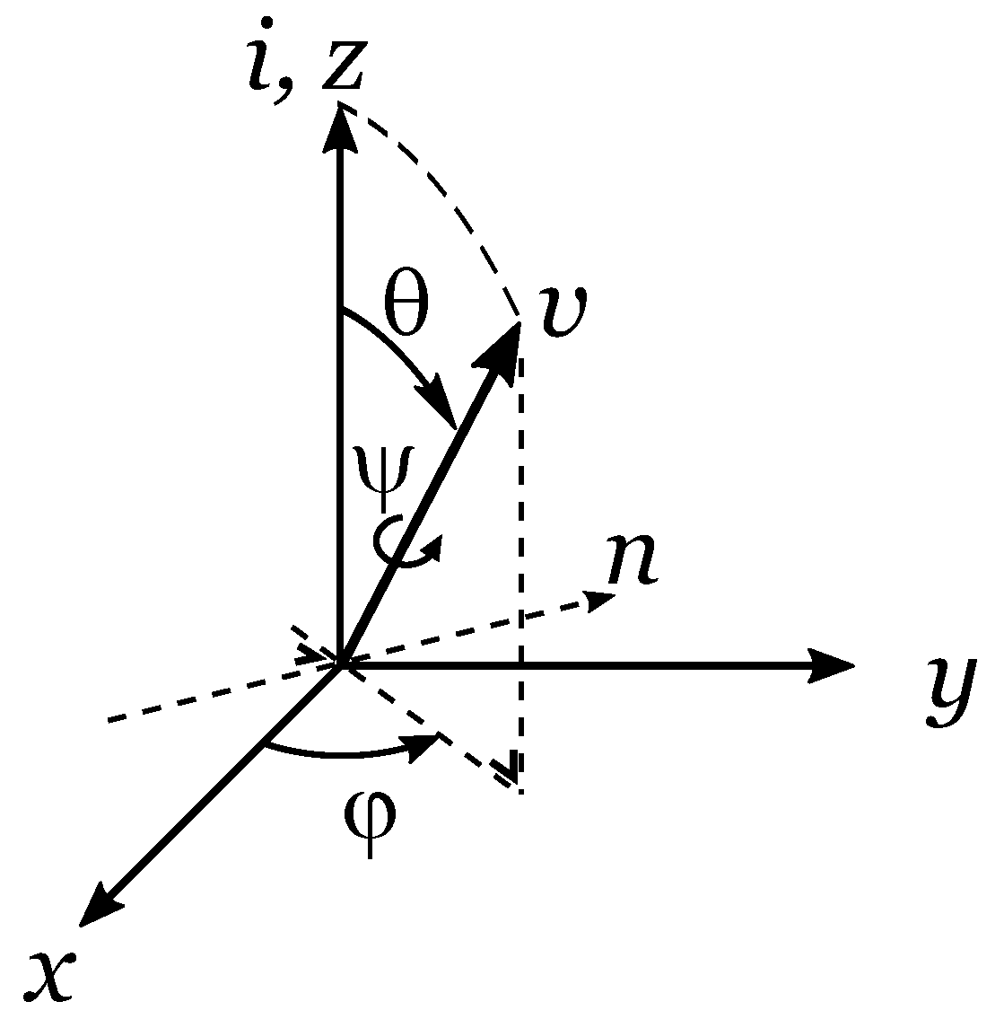
2.1. Definition of Specific Inertial Bodies and CV-Joint Kinematics
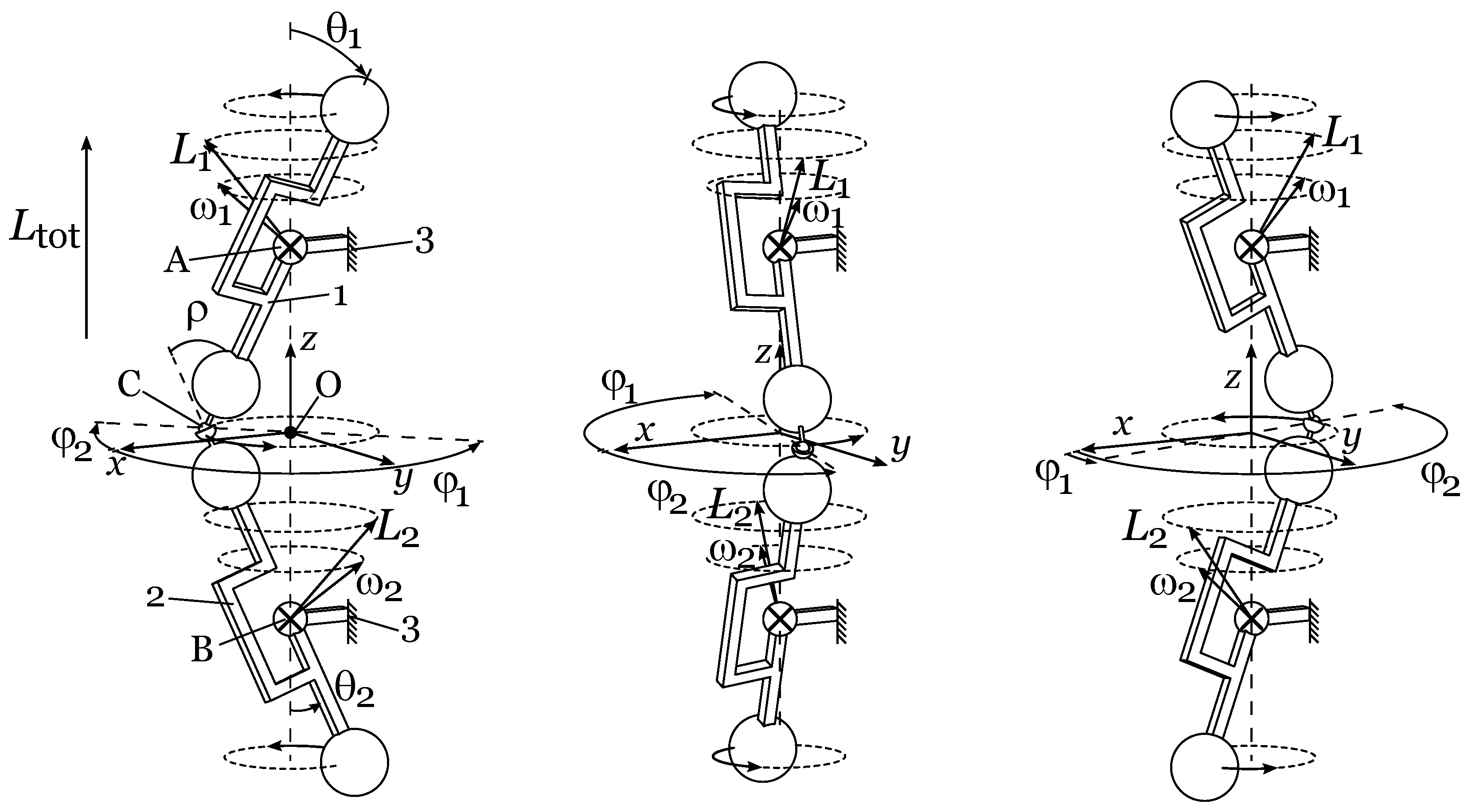
2.2. Description of the Mechanism and Working Principle
- One degree of freedom, i.e., the azimuth angle fully determines the position of both segments (1) and (2).
- For a constant velocity, , the total angular momentum of the mechanism is constant.
- The angular deflection of the two CV joints (A) and (B) in elevation remains constant at all times .
- The angular deflection of the ball joint (C) in elevation remains constant at all times and equal to .
- If the joints (A), (B), and (C) have positive isotropic (in the sense that the stiffness does not vary with , i.e., that the stiffness is the same for all tilting directions) angular stiffnesses, then the elastic potential energy of the mechanism remains constant at all times and the mechanism is statically balanced (i.e., the mechanism as a whole is zero force and is stable in any position). The total elastic potential energy of the mechanism may vary with if the flexure joints exhibit stiffness anisotropy. In this case, the actuation of the mechanism may be disturbed by one or multiple stable states.
- If the rigid bodies (1) and (2) are also spherical rigid bodies, then the inertia tensor of the mechanism as a whole remains constant at all times, and condition 5 is fulfilled.
2.3. Kinematics
2.3.1. Kinematics of Rigid Body 1
2.3.2. Kinematics of Rigid Body 2
2.3.3. Angular Momentum and Kinetic Energy of the Complete Mechanism
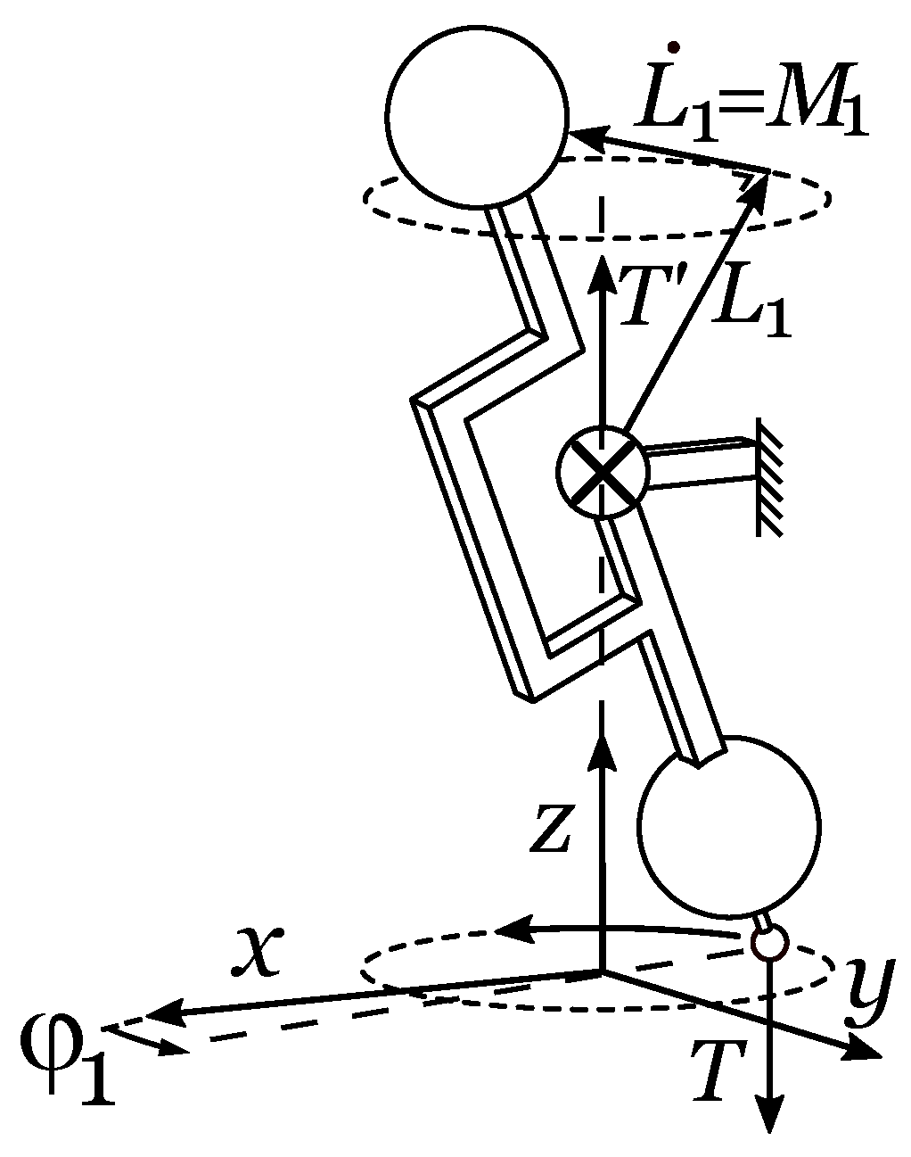
2.4. Joint Solicitation through Internal Forces
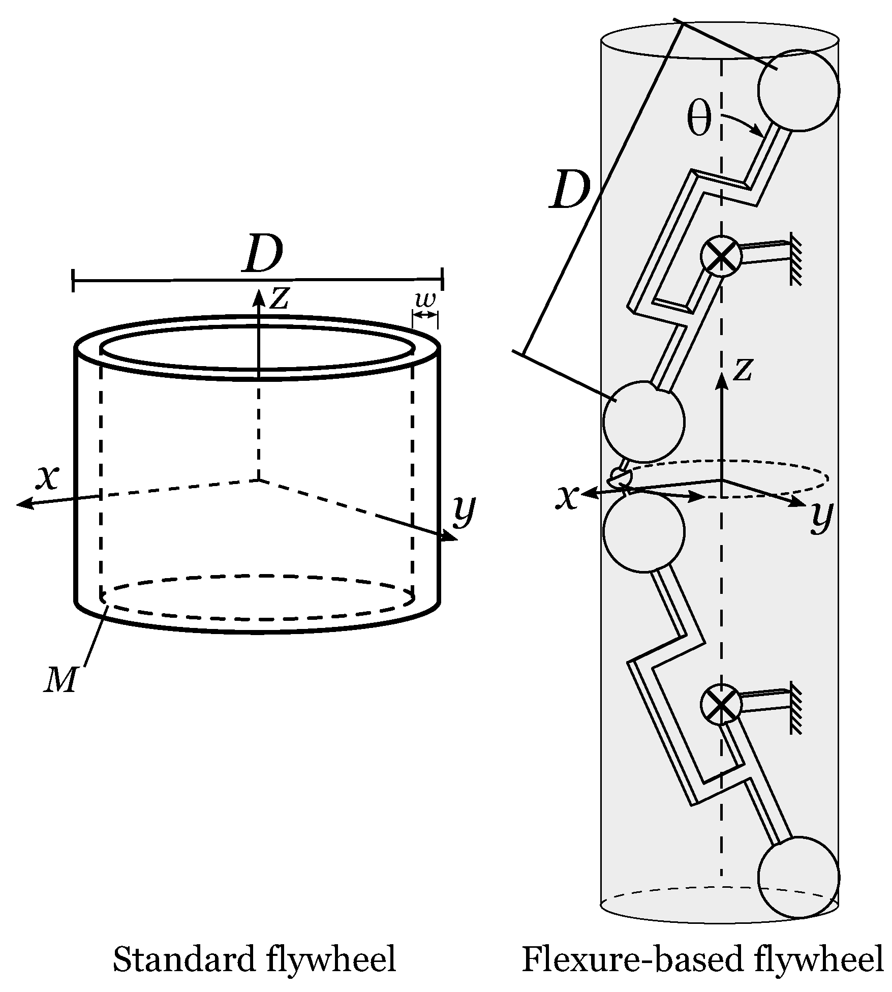
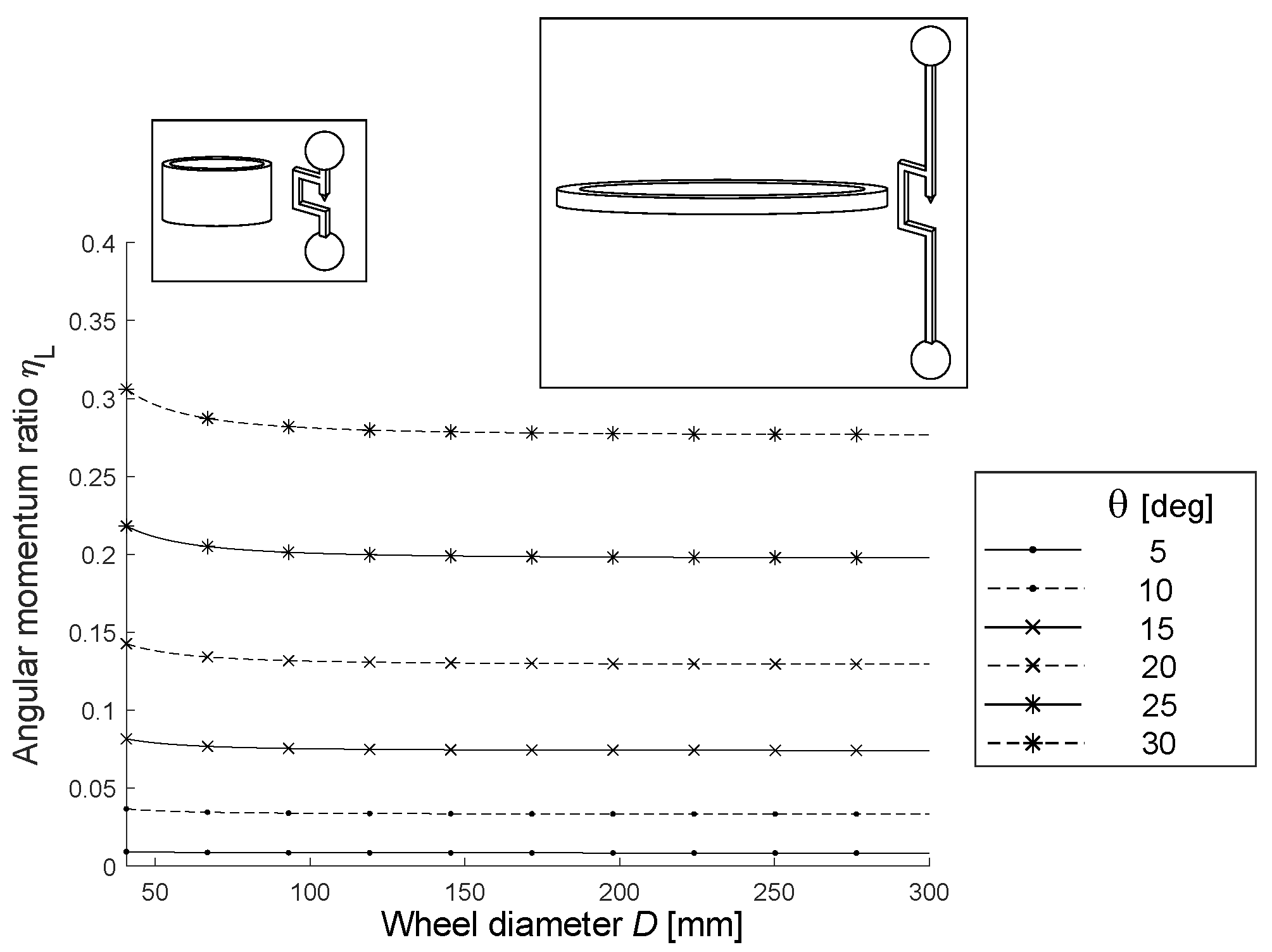
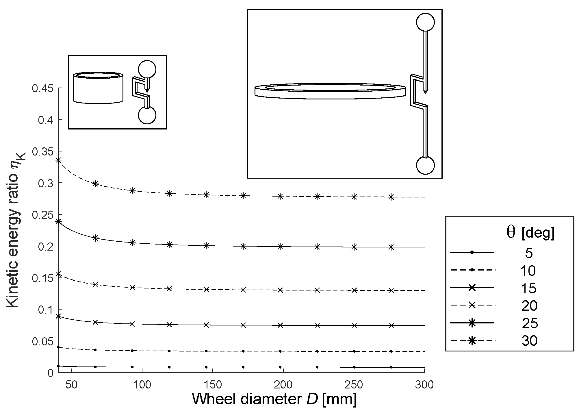
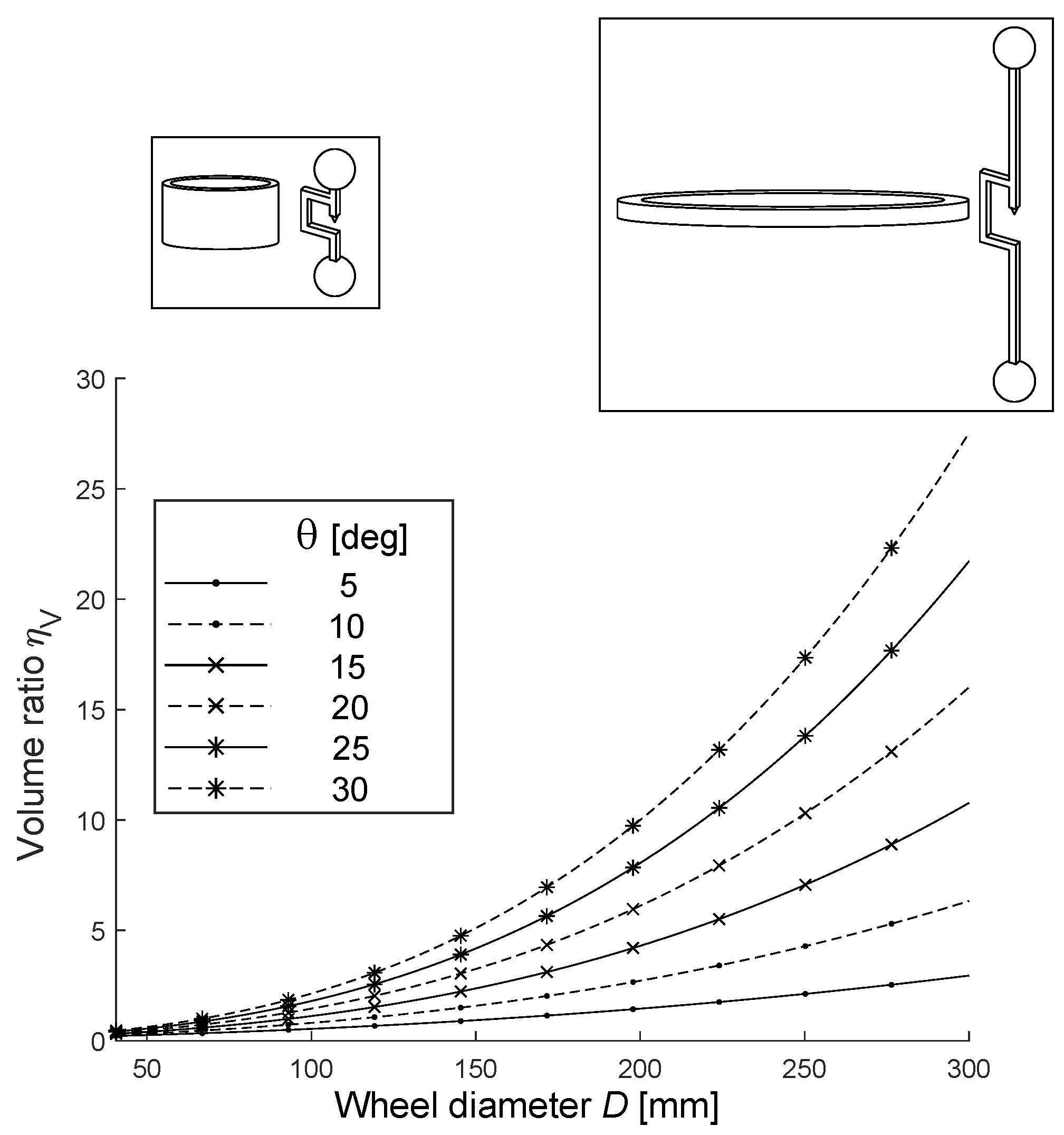
3. Comparison of a Dumbbell Flexure Design to a Standard Flywheel
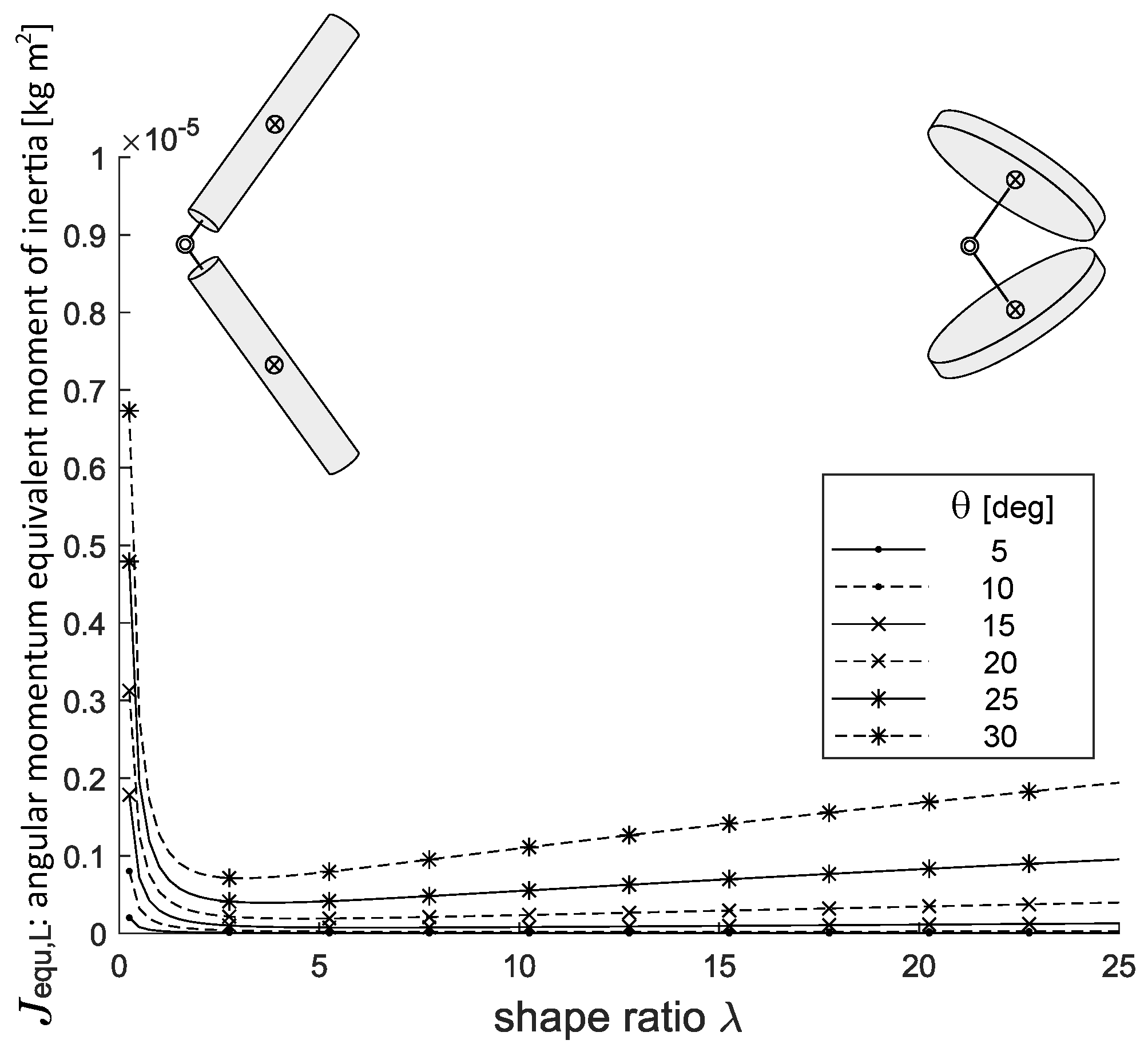
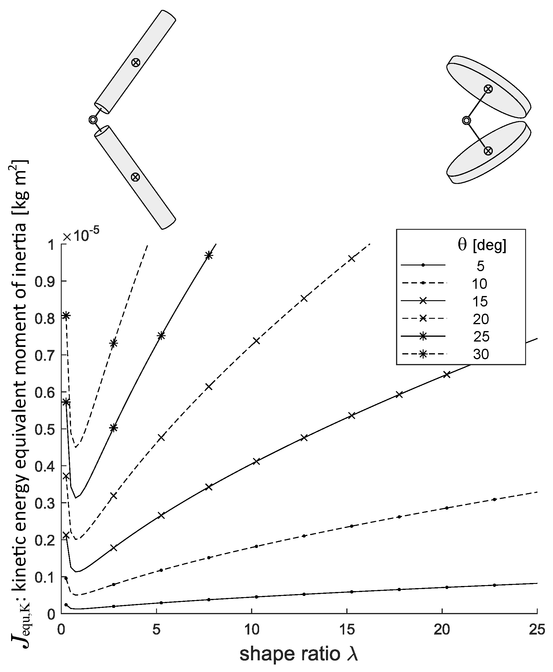
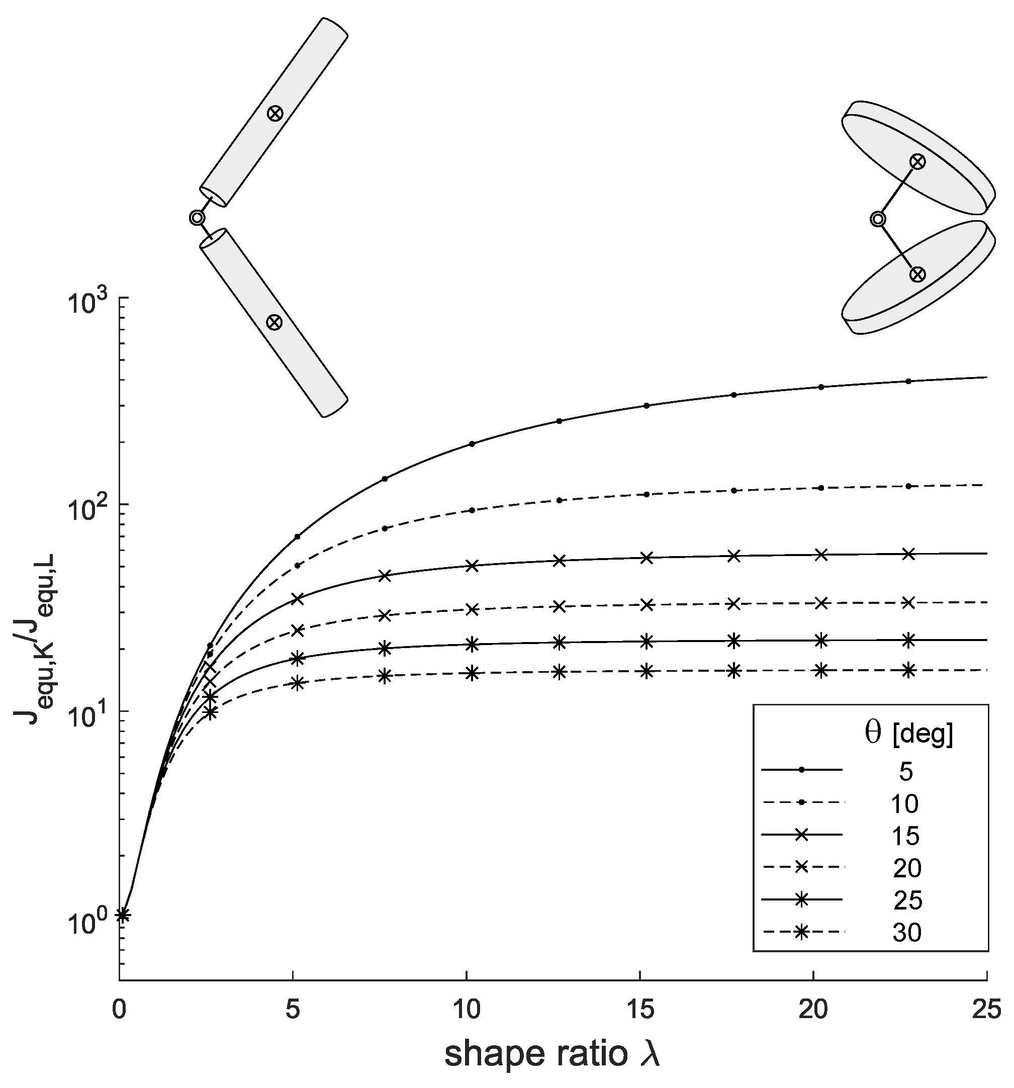
4. Influence of the Cylindrical Rigid Body Shape
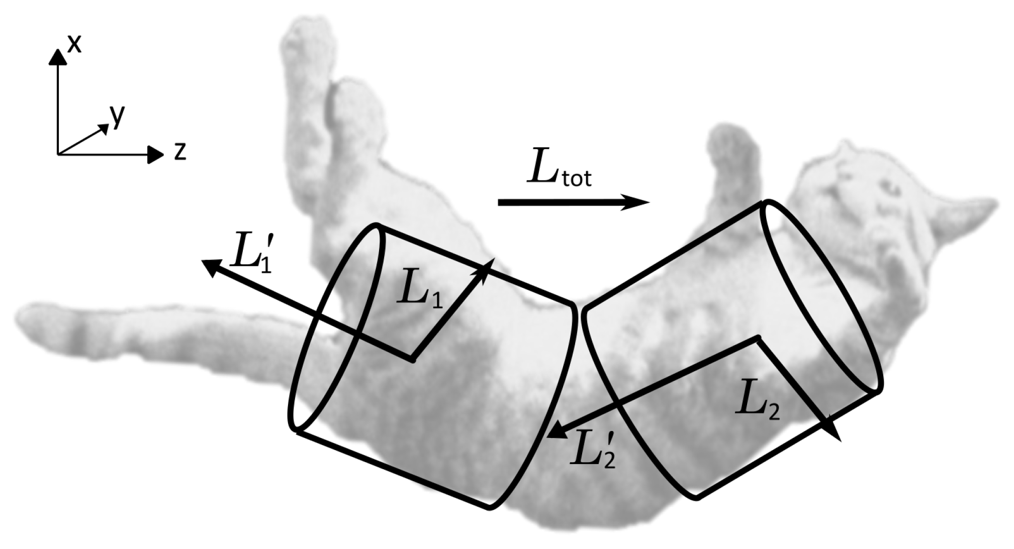
5. Analogy with a Falling Cat
6. Demonstrator Prototype of the Flywheel
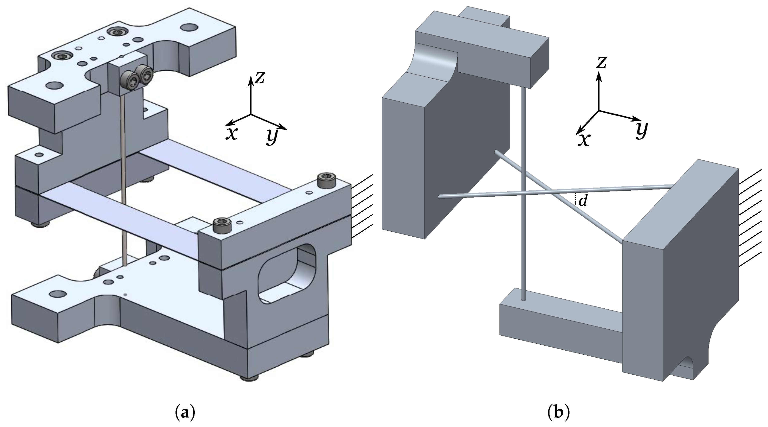
6.1. Constructed Demonstrator
6.2. Experimental Validation
6.2.1. Experimental Setup
6.2.2. Experimental Results
7. Discussion and Conclusions
Author Contributions
Funding
Data Availability Statement
Acknowledgments
Conflicts of Interest
Appendix A
References
- Mathews, T.; Nishanth, D. Flywheel Based Kinetic Energy Recovery Systems (KERS) Integrated in Vehicules. IJEST 2013, 5, 1694–1699, ISSN: 0975-5462. [Google Scholar]
- Heindel, S.; Liebold, F.; Sander, L. A Gas Bearing Reaction Wheel Supplied by Ultrasonic Pumps. In Proceedings of the 19th European Space Mechanisms and Tribology Symposium 2021, Online, 20–24 September 2021. [Google Scholar]
- Gerlach, B.; Ehinger, M.; Seiler, R. Low noise five-axis magnetic bearing reaction wheel. In Proceedings of the International Federation of Automatic Control (IFAC), Heidelberg, Germany, 15 September 2006. [Google Scholar] [CrossRef]
- Cosandier, F.; Henein, S.; Richard, M.; Rubbert, L. The Art of Flexure Mechanism Design; EPFL Press: Lausanne, Switzerland, 2017; ISBN 978-2-940222-56-8. [Google Scholar]
- Flückiger, P.; Henein, S.; Vardi, I.; Schneegans, H.; Tissot-Daguette, L. Flexure wheels for spacecraft attitude control. Eng. Arch. 2021. pre-print. [Google Scholar] [CrossRef]
- Schneegans, H.; De Jong, J.; Cosandier, F.; Henein, S. Mechanism Balancing Taxonomy. Mech. Mach. Theory 2024, 191, 105518. [Google Scholar] [CrossRef]
- Vardi, I.; Rubbert, L.; Bitterli, R.; Ferrier, N.; Kahrobaiyan, M.; Nussbaumer, B.; Henein, S. Theory and design of spherical oscillator mechanisms. Precis. Eng. 2018, 51, 499–513. [Google Scholar] [CrossRef]
- Guyou, M. Note relative à la communication de M. Marey. C. R. Acad. Sci. 1894, 119, 717–718. [Google Scholar]
- Rademaker, G.G.J.; Ter Braak, J.W.G. Das Umdrehen der fallenden Katze in der Luft. Acta Oto-Laryngol. 1936, 23, 313–343. [Google Scholar] [CrossRef]
- Kane, T.R.; Scher, M.P. A dynamical explanation of the falling cat phenomenon. Int. J. Solids Struct. 1969, 5, 663–670. [Google Scholar] [CrossRef]
- Cao, J.; Wang, S.; Zhu, X.; Song, L. A Review of Research on Falling Cat Phenomenon and Development of Bio-Falling Cat Robot. In Proceedings of the 4th WRC Symposium on Advanced Robotics and Automation 2022, Beijing, China, 20 August 2022. [Google Scholar] [CrossRef]
- Crane, R. A Cat Being Dropped Upside Down. Available online: https://www.shutterstock.com/editorial/image-editorial/cat-being-dropped-upside-down-demonstrate-how-12360717d (accessed on 18 March 2024).
- Mather, T.W.; Yim, M. Modular configuration design for a controlled fall. In Proceedings of the 2009 IEEE/RSJ International Conference on Intelligent Robots and Systems, St. Louis, MO, USA, 11–15 October 2009. [Google Scholar] [CrossRef]
- Crews, S.; Agrawal, S.; Velado, S. CatAstroΦ—Inertial Reorientation of a Freely Falling Cat Using Nonholonomic Motion Planning. Available online: https://www.youtube.com/watch?v=rq2wpRNUbDI (accessed on 18 March 2024).
- Garant, X.; Gosselin, G. Design and Experimental Validation of Reorientation Manoeuvres for a Free Falling Robot Inspired from the Cat Righting Reflex. IEEE Trans. Robot. 2021, 37, 482–493. [Google Scholar] [CrossRef]


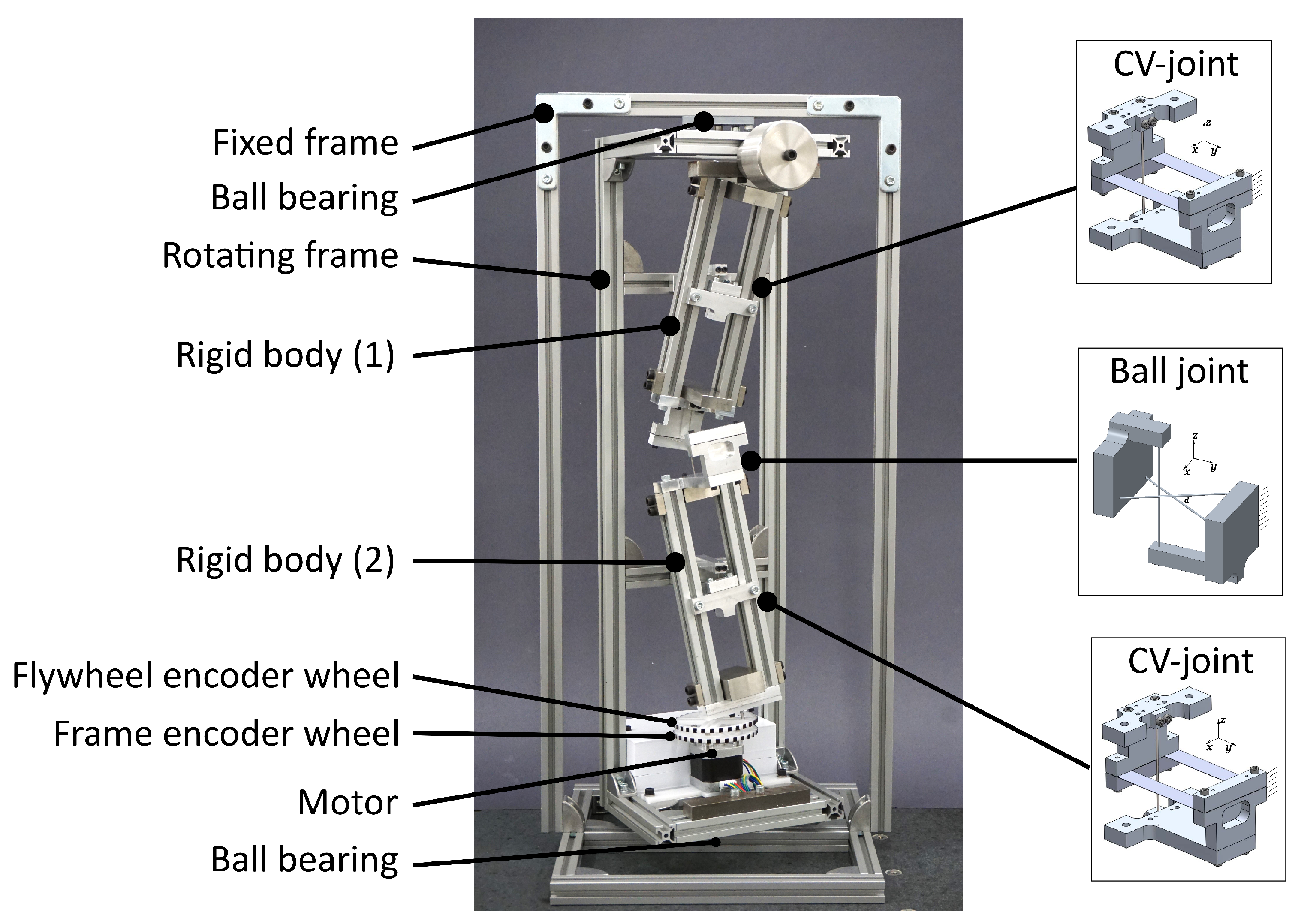
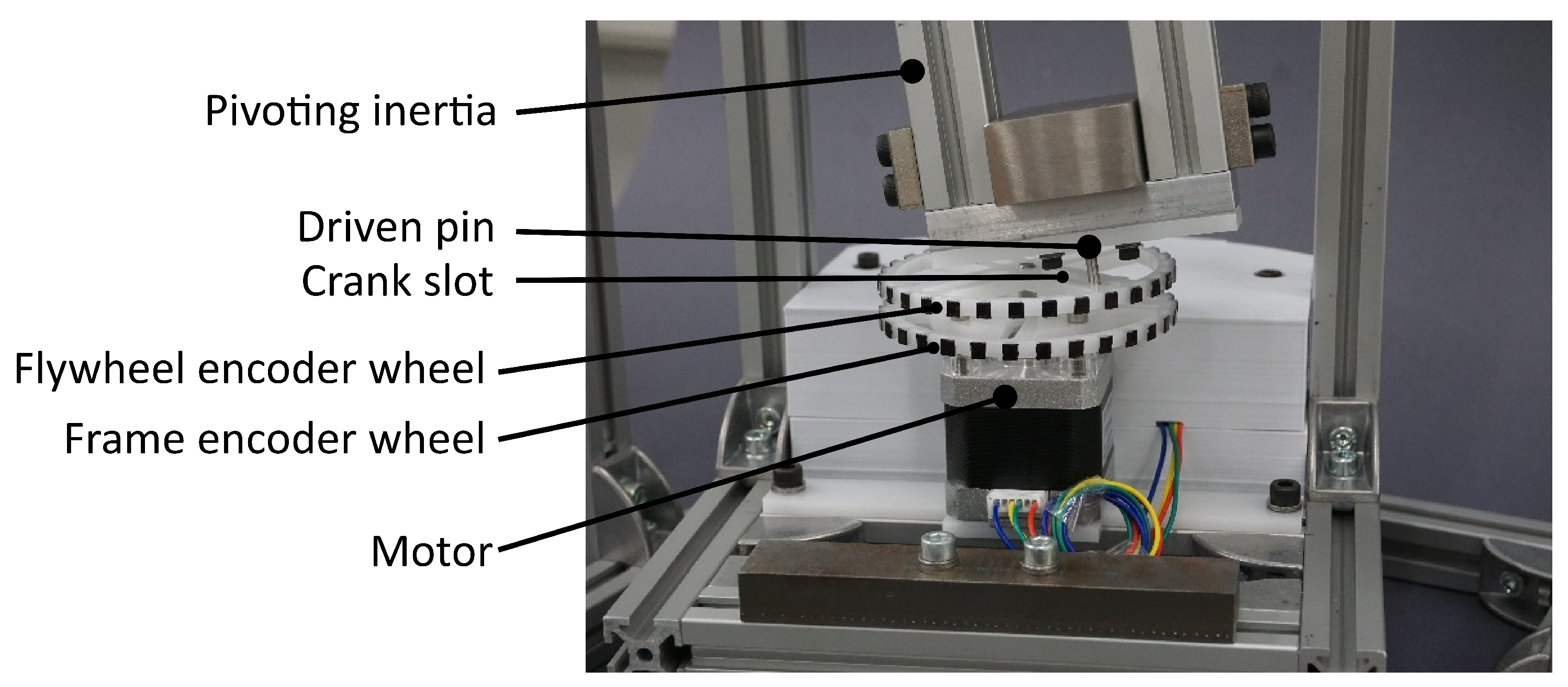
| Description | Name | Value [kg· m2] |
|---|---|---|
| Horizontal inertia of the pivoting body | ||
| Vertical inertia of the pivoting body | ||
| Vertical inertia of the frame | ||
| Vertical inertia of the rotor |
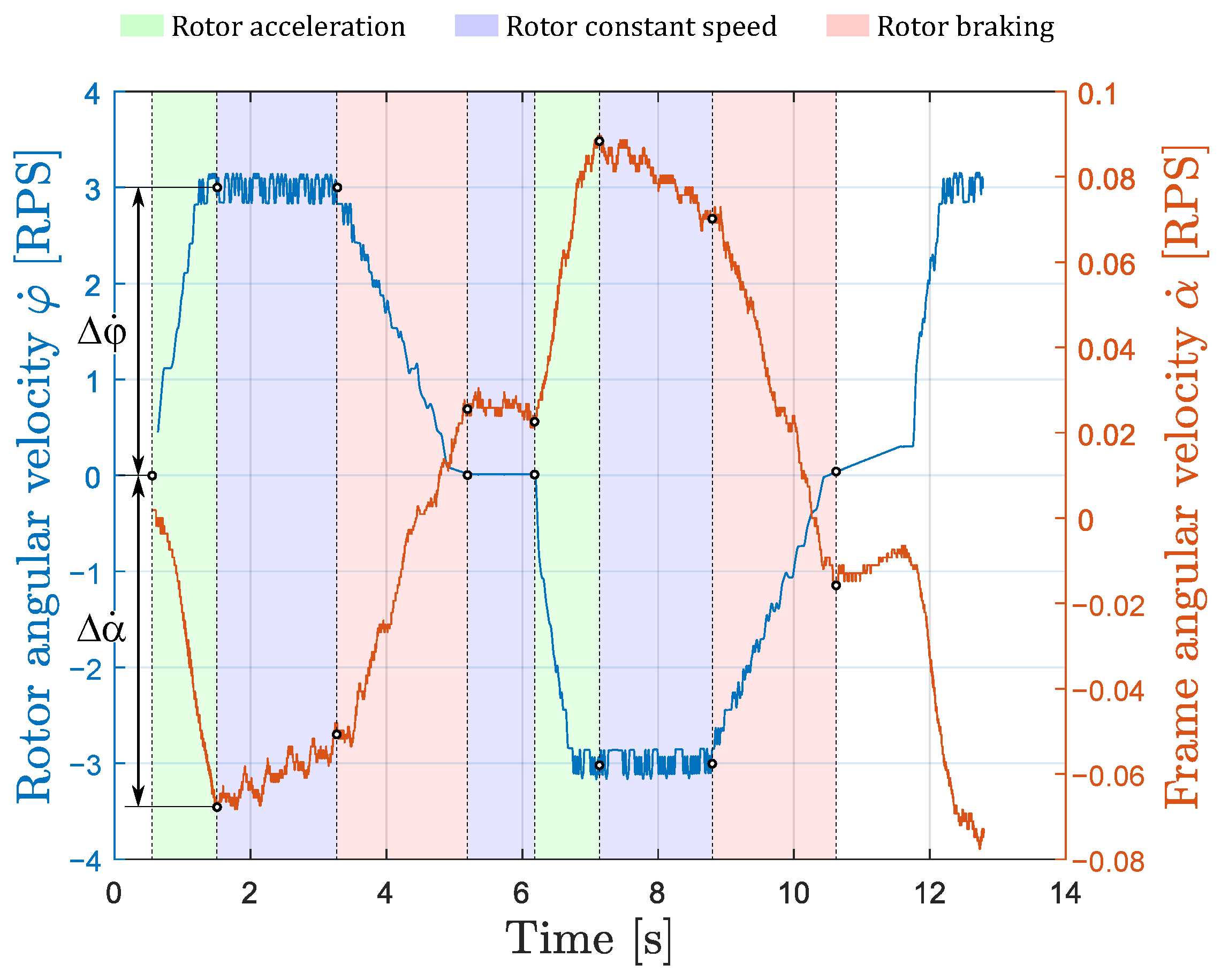
| Acceleration 1 | Braking 1 | Acceleration 2 | Braking 2 | |
|---|---|---|---|---|
| [RPS] | 3.0 | −3.0 | −3.0 | 3.0 |
| [RPS] | −0.0683 | 0.0776 | 0.0656 | −0.0849 |
| [/] | −43.9 | −38.7 | −45.7 | −35.3 |
Disclaimer/Publisher’s Note: The statements, opinions and data contained in all publications are solely those of the individual author(s) and contributor(s) and not of MDPI and/or the editor(s). MDPI and/or the editor(s) disclaim responsibility for any injury to people or property resulting from any ideas, methods, instructions or products referred to in the content. |
© 2024 by the authors. Licensee MDPI, Basel, Switzerland. This article is an open access article distributed under the terms and conditions of the Creative Commons Attribution (CC BY) license (https://creativecommons.org/licenses/by/4.0/).
Share and Cite
Flückiger, P.; Cosandier, F.; Schneegans, H.; Henein, S. Design of a Flexure-Based Flywheel for the Storage of Angular Momentum and Kinetic Energy. Machines 2024, 12, 232. https://doi.org/10.3390/machines12040232
Flückiger P, Cosandier F, Schneegans H, Henein S. Design of a Flexure-Based Flywheel for the Storage of Angular Momentum and Kinetic Energy. Machines. 2024; 12(4):232. https://doi.org/10.3390/machines12040232
Chicago/Turabian StyleFlückiger, Patrick, Florent Cosandier, Hubert Schneegans, and Simon Henein. 2024. "Design of a Flexure-Based Flywheel for the Storage of Angular Momentum and Kinetic Energy" Machines 12, no. 4: 232. https://doi.org/10.3390/machines12040232
APA StyleFlückiger, P., Cosandier, F., Schneegans, H., & Henein, S. (2024). Design of a Flexure-Based Flywheel for the Storage of Angular Momentum and Kinetic Energy. Machines, 12(4), 232. https://doi.org/10.3390/machines12040232


