Article

Sampled-Data Cooperative Adaptive Cruise Control for String-Stable Vehicle Platooning with Communication Delays: A Linear Matrix Inequality Approach

1
Automated Driving Technology Research Laboratory, Korea Automotive Technology Institute (KATECH), Cheonan 31214, Republic of Korea
2
Department of Electronics and Electrical Engineering, Dankook University, Yongin 16890, Republic of Korea
*
Author to whom correspondence should be addressed.
Machines 2024, 12(3), 165; https://doi.org/10.3390/machines12030165
Submission received: 18 January 2024 / Revised: 18 February 2024 / Accepted: 24 February 2024 / Published: 28 February 2024
(This article belongs to the Special Issue Autonomous Navigation of Mobile Robots and UAV)

Abstract

:
This study aims to propose a sampled-data control technique, utilizing a linear matrix inequality (LMI) approach, to achieve string-stable vehicle platooning in a cooperative adaptive cruise control (CACC) system with communication delays. To do this, a decentralized sampled-data controller design technique that combines one controller using sensor measurements and another one utilizing vehicle-to-vehicle (V2V) communication, ensuring both individual and string stability, is proposed first. Next, a memory sampled-data control (MSC) approach is presented to account for transmission delays in V2V communication. Additionally, an improved Lyapunov–Krasovskii functional (LKF) is presented to improve computational complexity and sampling performance. The design conditions are formulated as linear matrix inequalities (LMIs) in the time domain, facilitating efficient stability analysis and optimization. Finally, vehicle platooning simulations are provided to validate the effectiveness and feasibility of the proposed technique.

1. Introduction

Adaptive cruise control (ACC) is an established driver assistance technology that automatically adjusts a vehicle’s velocity to maintain a safe distance from the vehicle ahead [1]. ACC utilizes sensors such as radar or LiDAR to detect the distance and speed of the preceding vehicle, enabling the vehicle to autonomously accelerate or decelerate to match the traffic conditions. Recently, there has been a growing focus on cooperative adaptive cruise control (CACC), an expanded technology of ACC that improves safety, efficiency, and traffic flow through vehicle-to-vehicle (V2V) communication and collaboration [2,3]. This advanced expansion has sparked significant research interest and ongoing studies to investigate the potential benefits of CACC. In particular, CACC enables vehicles to form closely spaced groups called platoons, where vehicles move in a coordinated manner [4,5,6,7,8,9,10,11]. By enabling vehicles to exchange information, CACC enhances the coordination and cooperation among vehicles in a platoon. This cooperative aspect allows for more precise velocity control and tighter vehicle spacing, which can further reduce congestion and enhance fuel efficiency.
Meanwhile, guaranteeing string stability is crucial in vehicle platoon control to prevent disturbances or uncertainties from amplifying and causing instability. Achieving this often involves complex processes in the frequency domain, where parameters are manually determined to obtain a transfer function that represents the signal flow between the preceding and following vehicles while ensuring its magnitude remains limited to one [12,13,14,15,16,17]. Due to the inefficiency of determining parameters through trial and error in the frequency domain, recent studies [18,19] have proposed a controller synthesis method for CACC that applies a time domain definition to string stability and autonomously derives the parameters. When it becomes possible to analyze string stability in the time domain, controller design conditions can be expressed using linear matrix inequalities (LMIs), simplifying the process of specifying system requirements and constraints. Additionally, the use of LMIs enables efficient stability analysis and optimization, facilitating the evaluation of performance and robustness in platoon control systems. By considering the trade-off between performance and robustness, this approach contributes to the design of platoon control systems that achieve string stability while satisfying desired performance objectives.
In the CACC scheme, vehicles rely on both signals from the preceding vehicle measured by the sensors attached to the ego vehicle and transmitted via V2V communication. To facilitate V2V communication in CACC, sampled signals need to be utilized. Sampled signals significantly improve transmission efficiency by reducing the amount of data exchanged between vehicles. This conserves communication bandwidth, minimizes congestion on the communication channels, and enables efficient and reliable information exchange. In conclusion, the use of sampled signals in CACC offers advantages such as improved transmission efficiency and reliability, making the application of sampled-data control techniques practical and applicable in the development and implementation of CACC systems. However, considering that most studies on CACC have been conducted in the continuous-time domain, there is a need for ongoing studies on the sampled-data control approach [20] to CACC.
On the other hand, the constant time headway (CTH) strategy, which aims to maintain a fixed time gap between the preceding and following vehicles within a platoon, is widely used as the inter-vehicle spacing strategy in CACC systems [21,22]. To achieve this, information about the acceleration of the preceding vehicle is crucial. Without information about the preceding vehicle’s acceleration, the CACC system cannot effectively respond to changes in the preceding vehicle’s dynamics. As a result, the inter-vehicle travel time becomes variable, potentially leading to instability. Therefore, accurate and up-to-date information about the acceleration of the preceding vehicle is highly important for the CTH strategy in CACC. However, the acceleration of the preceding vehicle is obtained by the following vehicle through V2V communication, which also needs to consider the transmission delay. Thus, a decentralized controller design approach is necessary to flexibly incorporate feedback control based on sensor-acquired information and feedforward control based on information with delay obtained through communication.
In this context, applying conventional sampled-data control approaches to CACC systems is impractical due to the time delays that occur in V2V communication. Recently, research has been actively conducted on memory sampled-data control (MSC), an extended form of the conventional sampled-data control scheme, to address the issue of transmission delays between the sampler and the controller [23,24,25,26,27]. Therefore, the MSC approach can be introduced in CACC systems that rely on delayed data obtained through V2V communication to explicitly consider communication delays in the controller design and ensure control performance and stability.
Based on the observations mentioned above, this study proposes a sampled-data CACC technique that ensures string-stable vehicle platooning considering communication delays, using the LMI approach. Firstly, the CTH strategy is introduced to derive the platooning error dynamics in an interconnected form. The decentralized sampled-data controller is composed of a controller based on the measurements from the ego vehicle and another controller using the information on the preceding vehicle transmitted via V2V communication. To effectively consider the time delays caused by V2V communication, the MSC technique is applied, and a novel Lyapunov–Krasovskii functional (LKF) is introduced to improve sampling performance. The controller design conditions are formulated as an optimization problem in the form of LMIs, ensuring individual stability of all vehicles within the platoon and string stability of the platoon. Finally, simulation examples of vehicle platooning are provided to demonstrate the feasibility and effectiveness of the proposed design technique. The main contributions of this study can be summarized as follows:
  • This study introduces a practical CACC technique for vehicle platooning, incorporating the MSC technique to enhance the reliability of V2V communication.
  • The proposed controller design conditions, applicable to variable-sampling intervals, are established in the time domain as LMIs, simultaneously ensuring both individual stability and string stability.
  • An improved LKF, designed with partitioned sampling intervals and considering essential states for the CACC system configuration, is proposed. This improved LKF reduces conservatism in the design conditions of the sampled-data controller and optimizes computational complexity.
Notations: The notation R n represents an n-dimensional Euclidean space and R n × m denotes the set of all n × m real matrices. The identity matrix and the zero matrix of appropriate dimensions are denoted by I and 0 , respectively. An integer set 1 , 2 , , p is represented as I p for a positive integer p. The notation Sym X = X + X T is used to represent the shorthand form of a matrix X. For a symmetric matrix X, the notation X 0 ( X 0 ) indicates that X is positive (negative) definite. col and diag denote a column vector and a block-diagonal matrix, respectively. ∗ in the matrix represents the transposed element of its symmetric position. The space of functions ϕ : [ a , b ] R n , which are absolutely continuous on [ a , b ) , have a finite lim θ b ϕ ( θ ) and square-integrable first-order derivatives, denoted by W n [ a , b ) .

2. Problem Statement

2.1. Vehicle Longitudinal Dynamics

In this study, we consider the following third-order linear model describing the vehicle longitudinal dynamics, which is obtained using conventional exact feedback linearization to simplify its complexity [28]:
p ˙ i ( t ) = v i ( t ) v ˙ i ( t ) = a i ( t ) a ˙ i ( t ) = 1 ς u i ( t ) 1 ς a i ( t ) , i I N ,
where p i ( t ) , v i ( t ) , a i ( t ) , and u i ( t ) represent the position, velocity, acceleration, and control input of the i-th vehicle and ς is a time constant representing the engine dynamics of the vehicle.

2.2. Platooning Error Dynamics

This study considers the vehicles in a platoon with a predecessor-following (PF) topology. The actual inter-vehicle distance between the i-th vehicle and its predecessor vehicle is given by:
d i ( t ) = p i 1 ( t ) p i ( t ) .
In this paper, the CTH strategy, where each following vehicle maintains a constant time headway from the vehicle in front, is adopted [21]. Based on the CTH strategy, the desired spacing between the i-th vehicle and its predecessor vehicle can be expressed as follows:
d ^ i ( t ) = d s + λ v i ( t ) ,
where d s is the standstill distance and λ is the headway time.
Based on Equations (2) and (3), the spacing error is defined as
d ˜ i ( t ) = d i ( t ) d ^ i ( t ) = p i 1 ( t ) p i ( t ) d s λ v i ( t ) .
Definition 1.
The vehicle platooning with PF topology is said to be achieved if
lim t d ˜ i ( t ) = 0 and lim t v ˜ i ( t ) = 0 .
Now, the error dynamics are derived to achieve Equation (5). The time derivative of Equation (4) yields
d ˜ ˙ i ( t ) = v ˜ i ( t ) λ a i ( t ) ,
where v ˜ i ( t ) = v i 1 ( t ) v i ( t ) is the velocity error in the platoon with PF topology; thus, the time derivative of v ˜ i ( t ) is determined by
v ˜ ˙ i ( t ) = a i 1 ( t ) a i ( t ) .
By combining Equations (1), (6), and (7), the platooning error system can be obtained as the following interconnected form:
x ˙ i 1 ( t ) = A 1 x i 1 ( t ) + H x i 2 ( t ) + B 1 u i ( t ) x ˙ i 2 ( t ) = A 2 x i 2 ( t ) + B 2 u i 1 ( t ) ,
where
x i 1 = col d ˜ i ( t ) , v ˜ i ( t ) , a i ( t ) ; x i 2 = a i 1 ( t ) ; A 1 = 0 1 λ 0 0 1 0 0 1 ς ; H = 0 1 0 ; B 1 = 0 0 1 ς ; A 2 = 1 ς ; B 2 = 1 ς .
In this paper, we employ the MSC control scheme to achieve the platoon. Based on the MSC control scheme, we propose the platooning controller for the i-th vehicle as follows:
u i ( t ) = K 1 x i 1 ( t k ) + K 2 x i 2 t k τ for t [ t k , t k + 1 ) ,
where K 1 R 1 × 3 and K 2 R 1 are gain matrices to be determined, respectively; the k-th sampling time t k > 0 is defined for k Z 0 and satisfies t k + 1 t k = h k with an allowable variable-sampling interval h k [ h 1 , h 2 ] ; and τ > 0 is the communication delay that occurs when the vehicle receives information from the predecessor vehicle via V2V communication.
Remark 1.
In this study, considering the need to account for communication delays in obtaining the acceleration of the preceding vehicle through V2V communication, we choose to use the platooning error system in an interconnected form (8). By integrating a controller based on sensor information and another controller utilizing V2V communication, the decentralized sampled-data controller (Equation (9)) provides a comprehensive approach to addressing the complexities of the platooning system with communication delays.
Remark 2.
Applying the conventional sampled-data control approach directly to the CACC system cannot guarantee stability and control performance due to the time delays caused by V2V communication. Recently, studies on the MSC [23,24,26,27], an extended form of the sampled-data control, have shown potential in addressing the transmission delay issue between the sampler and the controller. Inspired by this, we introduce the MSC technique to the CACC system to address the challenge posed by communication delays. By effectively managing and compensating for communication delays, the MSC technique holds promise for improving the overall reliability and effectiveness of the CACC system, leading to safer and more efficient vehicle platooning.
Now, by substituting Equation (9) into Equation (8), we obtain the closed-loop error system, as follows:
x ˙ i 1 ( t ) = A 1 x i 1 ( t ) + H x i 2 ( t ) + B 1 K 1 x i 1 ( t k ) + B 1 K 2 x i 2 t k τ x ˙ i 2 ( t ) = A 2 x i 2 ( t ) + B 2 u i 1 ( t ) .
The problem below is provided to clarify the objective of the controller design proposed in this study.
Problem 1.
Design the decentralized sampled-data controller (9) in the platoon with the PF topology to meet the following criteria:
1 .
The equilibrium of x i 1 ( t ) is asymptotically stable when u i 1 ( t ) = 0 , ensuring individual stability;
2 .
The following inequality is guaranteed, which ensures string stability [29]:
S i ( t ) L 2 S i 1 ( t ) L 2 , 2 i N ,
which is satisfied by
0 t f S i T ( s ) S i ( s ) d s V ( 0 ) + 0 t f S i 1 T ( s ) S i 1 ( s ) d s ,
where t f is the termination time of control; S i ( t ) represents a signal that can correspond to either the spacing error d ˜ i ( t ) , the velocity v i ( t ) , the acceleration a i ( t ) , or the control input u i ( t ) of the i-th vehicle; and V ( 0 ) represents a value of the scalar function V ( t ) at t = 0 .
Remark 3.
In this study, we offer Problem 1, which provides control design conditions to ensure both individual vehicle stability within a platoon and string stability for the entire platoon simultaneously. Additionally, in this study, S i 1 ( t ) is set as u i ( t ) to ensure string stability for the spacing error d ˜ i ( t ) , the velocity v i ( t ) , and the acceleration a i ( t ) [18].

2.3. Required Lemmas

Before advancing to the next section, some lemmas are introduced.
Lemma 1
([30]). For any positive definite matrix R R n × n , any matrix Z of appropriate dimension, scalars ρ 1 and ρ 2 satisfying ρ 1 < ρ 2 , and vector functions ζ ( t ) and X : [ ρ 1 , ρ 2 ] R n , the following inequality always holds:
ρ 1 ρ 2 X T ( s ) R X ( s ) d s ( ρ 2 ρ 1 ) ζ T ( t ) Z R 1 Z T ζ ( t ) + 2 ζ T ( t ) Z ρ 1 ρ 2 X ( s ) d s .
Lemma 2
([31]). Let the vector function X ( t ) W n [ ρ 1 , ρ 2 ) and X ( ρ 1 ) = 0 for scalars ρ 1 and ρ 2 satisfying ρ 1 < ρ 2 . Then, for any positive definite matrix Q R n × n , the following inequality holds:
ρ 1 ρ 2 X T ( s ) Q X ( s ) d s 4 ( ρ 2 ρ 1 ) 2 π 2 ρ 1 ρ 2 X ˙ T ( s ) Q X ˙ ( s ) d s .

3. LMI-Based Sampled-Data Controller Design

In this study, the following LKF for the error system (Equation (10)) is considered:
V i ( t ) = j = 1 3 V i j ( t ) for t [ t k , t k + 1 ) ,
where
V i 1 ( t ) = x i 1 T ( t ) P i 1 x i 1 ( t ) + x i 2 T ( t ) P i 2 x i 2 ( t ) ; V i 2 ( t ) = ( t k + 1 t ) η ( t k , t ) t X 1 ( s ) T Q i 1 X 1 ( s ) d s + t k η ( t k , t ) X 1 ( s ) T Q i 2 X 1 ( s ) d s ; V i 3 ( t ) = ( h 2 + τ ) 2 t k τ t x ˙ i 2 T ( s ) R i x ˙ i 2 ( s ) d s π 2 4 t k τ t X 2 ( s ) T R i X 2 ( s ) d s ; Q i 1 = Q i 11 Q i 12 Q i 13 ; Q i 2 = Q i 21 Q i 22 Q i 23 ; X 1 ( t ) = col x i 1 ( t k ) , x ˙ i 1 ( t ) ; X 2 ( t ) = x i 2 ( t ) x i 2 ( t k τ ) ; η ( t k , t ) = t k + σ ( t t k ) for 0 < σ i < 1 ;
{ P i 1 , Q i 13 , Q i 23 } R 3 × 3 are positive definite matrices; P i 2 and R i are positive scalars; { Q i 11 , Q i 21 } R 3 × 3 are symmetric matrices; and { Q i 12 , Q i 22 } R 3 × 3 are full-rank matrices.
Remark 4.
In this study, inspired by [32,33], we introduce V i 2 ( t ) to the LKF, Equation (12). By dividing the time between consecutive sampling intervals into two segments and constructing separate Lyapunov functionals for each segment, V i 2 ( t ) can play a crucial role in extending the allowable sampling interval.
Remark 5.
Recent studies on the MSC, specifically considering both the delay states of the system and the controller, have employed the LKF proposed in [31]. However, it is worth noting that most of these studies focus on non-delay systems, yet they still apply the LKF proposed above without modifications [24,25,26,27]. Applying the aforementioned LKF directly to non-delay systems includes unnecessary states x ( t τ ) in their stability condition, resulting in the increased dimension of the required LKF and computational complexity. In order to address this issue, this study introduces the improved Lyapunov functional V i 3 ( t ) to overcome the problem of unnecessary states in the CACC system design. By proposing V i 3 ( t ) , this study effectively resolves the issue of unnecessary states, simplifies the controller design process, and reduces computational complexity.
In this section, the following vector and matrix notations are utilized to simplify the expressions:
ζ i ( t ) = col x i 1 ( t ) , x ˙ i 1 ( t ) , x i 1 ( t k ) , x i 1 η ( t k , t ) , x i 2 ( t ) , x ˙ i 2 ( t ) , x i 2 ( t k τ i ) , u i 1 ( t ) , I p = 0 n 1 × n 1 ( p 1 ) I n 1 × n 1 0 n 1 × { n 1 ( 4 p ) + 4 n 2 } T , I q + 4 = 0 n 2 × { 4 n 1 + n 2 ( q 1 ) } I n 2 × n 2 0 n 2 × n 2 ( 4 q ) T ,
where n 1 = 3 , n 2 = 1 , and { p , q } I 4 .
First, the following theorem provides a condition to determine whether the previously designed controller satisfies the design condition given in Problem 1.
Theorem 1.
For the given positive scalars α 1 , α 2 , β 1 , β 2 , τ, h 1 < h 2 , and σ < 1 and controller gains K 1 and K 2 of the sampled-data controller (Equation (9)), if there exist positive definite matrices P i 1 , Q i 13 , and Q i 23 ; positive scalars P i 2 and R i ; symmetric matrices Q i 11 and Q i 21 ; any full-rank matrices M i 1 , Q i 12 , Q i 22 , Z i 1 , and Z i 2 ; and any scalar M i 2 such that the following LMIs hold for ( i , s ) I N × I 2 , then the error system (Equation (10)) satisfies the design criteria stated in Problem 1:
Ω i 1 ( h s ) 0 ,
Ω i 2 ( h s ) 0 ,
where
Ω i 1 ( h s ) = Ψ i 1 + h s Ψ i 2 K T I ; Ω i 2 ( h s ) = Ψ i 1 + h s Ψ i 3 K T ( 1 σ ) h s Z i 1 σ h s Z i 2 I 0 0 ( 1 σ ) h s Q i 13 0 σ h s Q i 23 ; Ψ i 1 = ( h 2 + τ ) 2 I 6 R i I 6 T π 2 4 ( I 5 I 7 ) R i ( I 5 I 7 ) T I 8 I 8 T + S y m { I 1 P i 1 I 2 T + I 5 P i 2 I 6 T + ( I 3 Q i 12 + Z i 1 ) ( I 1 I 4 ) T + ( I 3 Q i 22 + Z i 2 ) ( I 4 I 3 ) T + Λ 1 M i 1 T I 2 T + A 1 I 1 T + H I 5 T + B 1 K 1 I 3 T + B 1 K 2 I 7 T + Λ 2 M i 2 T I 6 T + A 2 I 5 T + B 2 I 8 T } ; Ψ i 2 = I 3 I 1 Q i 1 I 3 I 1 T σ i I 3 I 4 ( Q i 1 Q i 2 ) I 3 I 4 ; Ψ i 3 = I 3 ( 1 σ ) Q i 11 + σ Q i 21 I 3 T ; K = K 1 I 3 T + K 2 I 7 T ; Λ 1 = I 1 + α 1 I 2 + α 2 I 3 ; Λ 2 = I 5 + β 1 I 6 + β 2 I 7 .
Proof. 
Differentiating V i 1 ( t ) with respect to t yields
V ˙ i 1 ( t ) = 2 x i 1 T ( t ) P i 1 x ˙ i 1 ( t ) + 2 x i 2 T ( t ) P i 2 x ˙ i 2 ( t ) = ζ i T ( t ) Sym I 1 P i 1 I 2 T + I 5 P i 2 I 6 T ζ i ( t ) .
Moreover, V i 2 ˙ ( t ) is obtained as follows:
V ˙ i 2 ( t ) = ( t k + 1 t ) X 1 ( t ) T Q i 1 X 1 ( t ) σ X 1 η ( t k , t ) T ( Q i 1 Q i 2 ) X 1 η ( t k , t ) ( t t k ) x i 1 T ( t k ) ( 1 σ ) Q i 11 + σ Q i 21 x i 1 ( t k ) 2 x i 1 T ( t k ) Q i 12 x i 1 ( t ) x i 1 η ( t k , t ) + Q i 22 x i 1 η ( t k , t ) x i 1 ( t k ) η ( t k , t ) t x ˙ i 1 ( s ) Q i 13 x ˙ i 1 ( s ) d s t k η ( t k , t ) x ˙ i 1 ( s ) Q i 23 x ˙ i 1 ( s ) d s .
By applying Lemma 1 to the integral terms in Equation (16), we obtain
η ( t k , t ) t x ˙ i 1 ( s ) Q i 13 x ˙ i 1 ( s ) d s ( t t k ) ( 1 σ ) ζ i T ( t ) Z i 1 Q i 13 1 Z i 1 T ζ i ( t ) + 2 ζ i T ( t ) Z i 1 x i 1 ( t ) x i 1 η ( t k , t ) , t k η ( t k , t ) x ˙ i 1 ( s ) Q i 23 x ˙ i 1 ( s ) d s
( t t k ) σ ζ i T ( t ) Z i 2 Q i 23 1 Z i 2 T ζ i ( t ) + 2 ζ i T ( t ) Z i 2 x i 1 η ( t k , t ) x i 1 ( t k ) ,
where Z i p with p I 2 is a full-rank matrix of appropriate dimension. Considering inequalities (17) and (18) in Equation (16) yields
V ˙ i 2 ( t ) ζ i T ( t ) [ Sym ( I 3 Q i 12 + Z i 1 ) ( I 1 I 4 ) T + ( I 3 Q i 22 + Z i 2 ) ( I 4 I 3 ) T + ( t t k ) I 3 ( 1 σ ) Q i 11 + σ Q i 21 I 3 T + ( 1 σ ) Z i 1 Q i 13 1 Z i 1 T + σ Z i 2 Q i 23 1 Z i 2 T + ( t k + 1 t ) I 3 I 1 Q i 1 I 3 I 1 T σ I 3 I 4 ( Q i 1 Q i 2 ) I 3 I 4 ] ζ i ( t ) .
Lastly, V ˙ i 3 ( t ) becomes
V ˙ i 3 ( t ) = ( h i 2 + τ ) 2 x ˙ i 2 ( t ) R i x ˙ i 2 ( t ) π 2 4 X 2 ( t ) T R i X 2 ( t ) = ζ i T ( t ) ( h 2 + τ ) 2 I 6 R i I 6 T π 2 4 ( I 5 I 7 ) R i ( I 5 I 7 ) T ζ i ( t ) .
On the other hand, based on the error system (Equation (10)), it can be derived that the following equations hold for any full-rank matrix M i 1 R 3 and any scalar M i 2 :
0 = 2 M i 1 x i 1 ( t ) + α 1 M i 1 x ˙ i 1 ( t ) + α 2 M i 1 x i 1 ( t k ) T × x ˙ i 1 ( t ) + A 1 x i 1 ( t ) + H x i 2 ( t ) + B 1 K 1 x i 1 ( t k ) + B 1 K 2 x i 2 ( t k τ ) = ζ i T ( t ) 2 ( I 1 M i 1 T + α 1 I 2 M i 1 T + α 2 I 3 M i 1 T ) ( I 2 T + A 1 I 1 T + H I 5 T + B 1 K 1 I 3 T + B 1 K 2 I 7 T ) ζ i ( t ) = ζ i T ( t ) Sym Λ 1 M i 1 T I 2 T + A 1 I 1 T + H I 5 T + B 1 K 1 I 3 T + B 1 K 2 I 7 T ζ l ( t ) ,
0 = 2 M i 2 x i 2 ( t ) + β 1 M i 2 x ˙ i 2 ( t ) + β 2 M i 2 x i 2 ( t k τ ) T x ˙ i 2 ( t ) + A 2 x i 2 ( t ) + B 2 u i 1 ( t ) = ζ i T ( t ) 2 ( I 5 M i 2 T + β 1 I 6 M i 2 T + β 2 I 7 M i 2 T ) ( I 6 T + A 2 I 5 T + B 2 I 8 T ) ζ i ( t ) = ζ i T ( t ) Sym Λ 2 M i 2 T ( I 6 T + A 2 I 5 T + B 2 I 8 T ) ζ i ( t ) ,
where α p and β p with p I 2 are given positive scalars, Λ 1 = I 1 + α 1 I 2 + α 2 I 3 , and Λ 2 = I 5 + β 1 I 6 + β 2 I 7 .
Then, by combining Equations (15) and (20)–(22) and inequality (19) into a single inequality, we can obtain
V ˙ i ( t ) ζ i T ( t ) [ ( h 2 + τ ) 2 I 6 R i I 6 T π 2 4 ( I 5 I 7 ) R i ( I 5 I 7 ) T + Sym { I 1 P i 1 I 2 T + I 5 P i 2 I 6 T + ( I 3 Q i 12 + Z i 1 ) ( I 1 I 4 ) T + ( I 3 Q i 22 + Z i 2 ) ( I 4 I 3 ) T + Λ 1 M i 1 T I 2 T + A 1 I 1 T + H I 5 T + B 1 K 1 I 3 T + B 1 K 2 I 7 T + Λ 2 M i 2 T I 6 T + A 2 I 5 T + B 2 I 8 T } + ( t k + 1 t ) I 3 I 1 Q i 1 I 3 I 1 T σ i I 3 I 4 ( Q i 1 Q i 2 ) I 3 I 4 + ( t t k ) I 3 ( 1 σ ) Q i 11 + σ Q i 21 I 3 T + ( 1 σ ) Z i 1 Q i 13 1 Z i 1 T + σ Z i 2 Q i 23 1 Z i 2 T ζ i ( t ) ] .
To satisfy the inequality (11) stated in Problem 1, we add J i ( t ) = u i T ( t ) u i ( t ) u i 1 T ( t ) u i 1 ( t ) to both sides of inequality (23), which results in the following:
V ˙ i ( t ) + J i ( t ) ζ i T ( t ) [ Ψ i 1 + K T K + σ Z i 2 Q i 23 1 Z i 2 T + ( t k + 1 t ) Ψ i 2 + ( t t k ) Ψ i 3 + ( 1 σ ) Z i 1 Q i 13 1 Z i 1 T ] ζ i ( t ) ,
where
Ψ i 1 = ( h 2 + τ ) 2 I 6 R i I 6 T π 2 4 ( I 5 I 7 ) R i ( I 5 I 7 ) T I 8 I 8 T + Sym { I 1 P i 1 I 2 T + I 5 P i 2 I 6 T + ( I 3 Q i 12 + Z i 1 ) ( I 1 I 4 ) T + ( I 3 Q i 22 + Z i 2 ) ( I 4 I 3 ) T + Λ 1 M i 1 T I 2 T + A 1 I 1 T + H I 5 T + B 1 K 1 I 3 T + B 1 K 2 I 7 T + Λ 2 M i 2 T I 6 T + A 2 I 5 T + B 2 I 8 T } ; Ψ i 2 = I 3 I 1 Q i 1 I 3 I 1 T σ I 3 I 4 ( Q i 1 Q i 2 ) I 3 I 4 ; Ψ i 3 = I 3 ( 1 σ ) Q i 11 + σ Q i 21 I 3 T ; K = K 1 I 3 T + K 2 I 7 T .
From inequality (24) and h k = t k + 1 t k , it is obvious that V ˙ i ( t ) + J i ( t ) < 0 is guaranteed by
t k + 1 t h k ( Ψ i 1 + K T K + h k Ψ i 2 ) + t t k h k Ψ i 1 + K T K + h k Ψ i 3 + ( 1 σ ) Z i 1 Q i 13 1 Z i 1 T + σ Z i 2 Q i 23 1 Z i 2 T 0 .
Moreover, since inequality (25) is convex in t [ t k , t k + 1 ) , it implies that inequality (25) holds when the following inequalities are simultaneously fulfilled
Ψ i 1 + K T K + h k Ψ i 2 0 ,
Ψ i 1 + K T K + h k Ψ i 3 + ( 1 σ ) Z i 1 Q i 13 1 Z i 1 T + σ Z i 2 Q i 23 1 Z i 2 T 0 .
Applying the Schur complements to both inequalities (26) and (27) yields
Ω i 1 ( h k ) = Ψ i 1 + h k Ψ i 2 K T I 0 , Ω i 2 ( h k ) = Ψ i 1 + h k Ψ i 3 K T ( 1 σ ) h k Z i 1 σ h k Z i 2 I 0 0 ( 1 σ ) h k Q i 13 0 σ h k Q i 23 0 .
Considering that Ω i p ( h k ) with p I 2 above is convex in h k [ h 1 , h 2 ] , we obtain
Ω i p ( h k ) : = h 2 h k h 2 h 1 Ω i p ( h 1 ) + h k h 1 h 2 h 1 Ω i p ( h 2 ) 0 ,
which is ensured by
Ω i p ( h s ) 0 for ( p , s ) I 2 × I 2 .
Therefore, if the LMIs (inequalities (13) and (14)) hold, we obtain
V ˙ i ( t ) + J i ( t ) 0 .
Under u i 1 ( t ) = 0 , it follows from inequality (28) that
V ˙ i ( t ) u i T ( t ) u i ( t ) 0 .
Next, we show the positive definiteness of V i ( t ) by requiring it to be positive definite only at sampling instants. From Equation (12), it can be confirmed that
lim t t k V i 1 ( t ) = V i 1 ( t k ) 0 , lim t t k V i 2 ( t ) = lim t t k + V i 2 ( t ) = V i 2 ( t k ) = 0 .
However, V i 3 ( t ) is discontinuous at t = t k . Hence, we need to establish both the positive definiteness of V i 3 ( t ) and that the jumps of V i 3 ( t ) at t k do not increase, i.e., V i 3 ( t k ) = 0 . As X 2 ( t ) X 2 ( t k τ ) = 0 when t = t k τ , and applying Lemma 2 to the last term in V i 3 ( t ) yields
V i 3 ( t ) φ ( t ) t k τ t x ˙ i 2 T ( s ) R i x ˙ i 2 ( s ) d s = W 1 ( t ) + W 2 ( t ) ,
where
φ ( t ) = ( h 2 + τ ) 2 ( t t k + τ ) 2 ; W 1 ( t ) = φ ( t ) t τ t x ˙ i 2 T ( s ) R i x ˙ i 2 ( s ) d s ; W 2 ( t ) = φ ( t ) t k τ t τ x ˙ i 2 T ( s ) R i x ˙ i 2 ( s ) d s .
Since φ ( t ) > 0 , W 1 ( t ) 0 , and W 2 ( t k ) = 0 , we have lim t t k V i 3 ( t ) V i 3 ( t k ) 0 . Therefore, it can be concluded that lim t t k V i ( t ) = V i ( t k ) . Consequently, from inequality (29), we obtain V i ( t ) V i ( t k + 1 ) 0 , which implies the positive definiteness of V i ( t ) . Thus, we can ensure that the equilibrium of Equation (10) is asymptotically stable, satisfying the first condition stated in Problem 1.
In addition, integrating the inequality (28) from 0 to t f yields
V i ( t f ) V i ( 0 ) + 0 t f J i ( s ) d s 0 .
From V i ( t f ) 0 for t f > 0 , it can be concluded that the second condition given in Problem 1 is also met. This completes the proof of Theorem 1. □
The objective of this study is now to find the controller gains K 1 and K 2 in Theorem 1. If the controller gains are not given, the matrix inequalities (13) and (14) in Theorem 1 are not LMIs, which cannot be solved via contemporary numerical solvers. Thus, we provide the following theorem to reformulate the condition as LMIs:
Theorem 2.
For the given positive scalars α 1 , α 2 , β 1 , β 2 , τ, h 1 < h 2 , and σ < 1 , if there exist positive definite matrices P ¯ i 1 , Q ¯ i 13 , and Q ¯ i 23 ; positive scalars P ¯ i 2 and R ¯ i ; symmetric matrices Q ¯ i 11 and Q ¯ i 21 ; any full-rank matrices M ¯ i 1 , Q ¯ i 12 , Q ¯ i 22 , Z ¯ i 1 , and Z ¯ i 2 ; and any scalar M ¯ i 2 such that the following LMIs hold for ( i , s ) I N × I 2 , then the error system (Equation (10)) fulfills the design criteria presented in Problem 1 with the obtained controller gains K 1 and K 2 :
Ω ¯ i 1 ( h s ) 0 ,
Ω ¯ i 2 ( h s ) 0 ,
where
Ω ¯ i 1 ( h s ) = Ψ ¯ i 1 + h s Ψ ¯ i 2 K ¯ T I ; Ω ¯ i 2 ( h s ) = Ψ ¯ i 1 + h s Ψ ¯ i 3 K ¯ T ( 1 σ ) h s Z ¯ i 1 σ h s Z ¯ i 2 I 0 0 ( 1 σ ) h s Q ¯ i 13 0 σ h s Q ¯ i 23 ; Ψ ¯ i 1 = ( h 2 + τ ) 2 I 6 R ¯ i I 6 T π 2 4 ( I 5 I 7 ) R ¯ i ( I 5 I 7 ) T I 8 I 8 T + S y m { I 1 P ¯ i 1 I 2 T + I 5 P ¯ i 2 I 6 T + ( I 3 Q ¯ i 12 + Z ¯ i 1 ) ( I 1 I 4 ) T + ( I 3 Q ¯ i 22 + Z ¯ i 2 ) ( I 4 I 3 ) T + Λ 1 M ¯ i 1 I 2 T + A 1 M ¯ i 1 I 1 T + H M ¯ i 2 I 5 T + B 1 K 1 M ¯ i 1 I 3 T + B 1 K 2 M ¯ i 2 I 7 T + Λ 2 M ¯ i 2 I 6 T + A 2 M ¯ i 2 I 5 T + B 2 I 8 T } ; Ψ ¯ i 2 = I 3 I 1 Q ¯ i 1 I 3 I 1 T σ I 3 I 4 ( Q ¯ i 1 Q ¯ i 2 ) I 3 I 4 ; Ψ ¯ i 3 = I 3 ( 1 σ ) Q ¯ i 11 + σ Q ¯ i 21 I 3 T ; K ¯ = K ¯ 1 I 3 T + K ¯ 2 I 7 T .
The definitions of the remaining terms are identical to those provided in Theorem 1. Additionally, the controller gains can be obtained from the solution by K 1 = K ¯ 1 M ¯ i 1 1 and K 2 = K ¯ 2 M ¯ i 2 1 .
Proof. 
For j I 2 , let M ¯ i j = M i j 1 , P ¯ i j = M ¯ i j T P i j M ¯ i j , Q ¯ i j = M ¯ i 1 T Q i j M ¯ i 1 , R ¯ i = M ¯ i 2 T R i M ¯ i 2 , Z ¯ i j = M ¯ i 1 T Z i j M ¯ i 1 , K ¯ j = K j M ¯ i j , Φ 1 = diag { M ¯ i 1 , M ¯ i 1 , M ¯ i 1 , M ¯ i 1 , M ¯ i 2 , M ¯ i 2 , M ¯ i 2 , I , I } , and Φ 2 = diag { M ¯ i 1 , M ¯ i 1 , M ¯ i 1 , M ¯ i 1 , M ¯ i 2 , M ¯ i 2 , M ¯ i 2 , I , I , M ¯ i 1 , M ¯ i 1 } . Then, by applying a congruence transformation with Φ 1 to Ω i 1 ( h s ) in inequality (13) and with Φ 2 to Ω i 2 ( h s ) in inequality (14), we can obtain the LMIs (inequalities (30) and (31), respectively). This concludes the proof. □

4. Simulation

In this section, vehicle platooning simulations are provided to demonstrate the efficiency and validity of the proposed method. All simulations were performed using MATLAB 2023a, with YALMIP [34] serving as the interface for solving the LMIs, and MOSEK [35] utilized as the solver.
We considered a platoon consisting of six vehicles, with one vehicle as the leader. All vehicles had the same dynamics, as given in Equation (1), with a time constant of ς = 0.3 . The communication delay with the preceding vehicle was assumed to be τ = 150 (ms). In addition, for the vehicle spacing, the CTH strategy (Equation (3)) is adopted, with d s = 3 [m] and λ = 0.75 .
Assuming a variable-sampling interval h k [ h 1 , h 2 ] = [ 0.001 , 0.1 ] and solving for the LMIs given in Theorem 2 by setting ( α 1 , α 2 , β 1 , β 2 , σ ) = ( 4.2 , 22 , 0.3 , 1.2 , 0.1 ) , we obtained the following controller gains:
K 1 = 0.3312 2.3104 0.9364 , K 2 = 0.1545 .
Using the controller gains obtained above, we conducted a vehicle platooning simulation with p 1 ( 0 ) = 5 d s , p 2 ( 0 ) = 4 d s , p 3 ( 0 ) = 3 d s , p 4 ( 0 ) = 2 d s , p 5 ( 0 ) = d s , p 6 ( 0 ) = 0 , and v 1 ( 0 ) = v 2 ( 0 ) = v 3 ( 0 ) = v 4 ( 0 ) = v 5 ( 0 ) = v 6 ( 0 ) = 0 . The reference speed and acceleration of the leader vehicle are controlled by the reference input u 1 ( t ) , which was set as follows:
u 1 ( t ) = 2 , t [ 0 , 10 ] 1.5 , t [ 30 , 40 ] 0 , else .
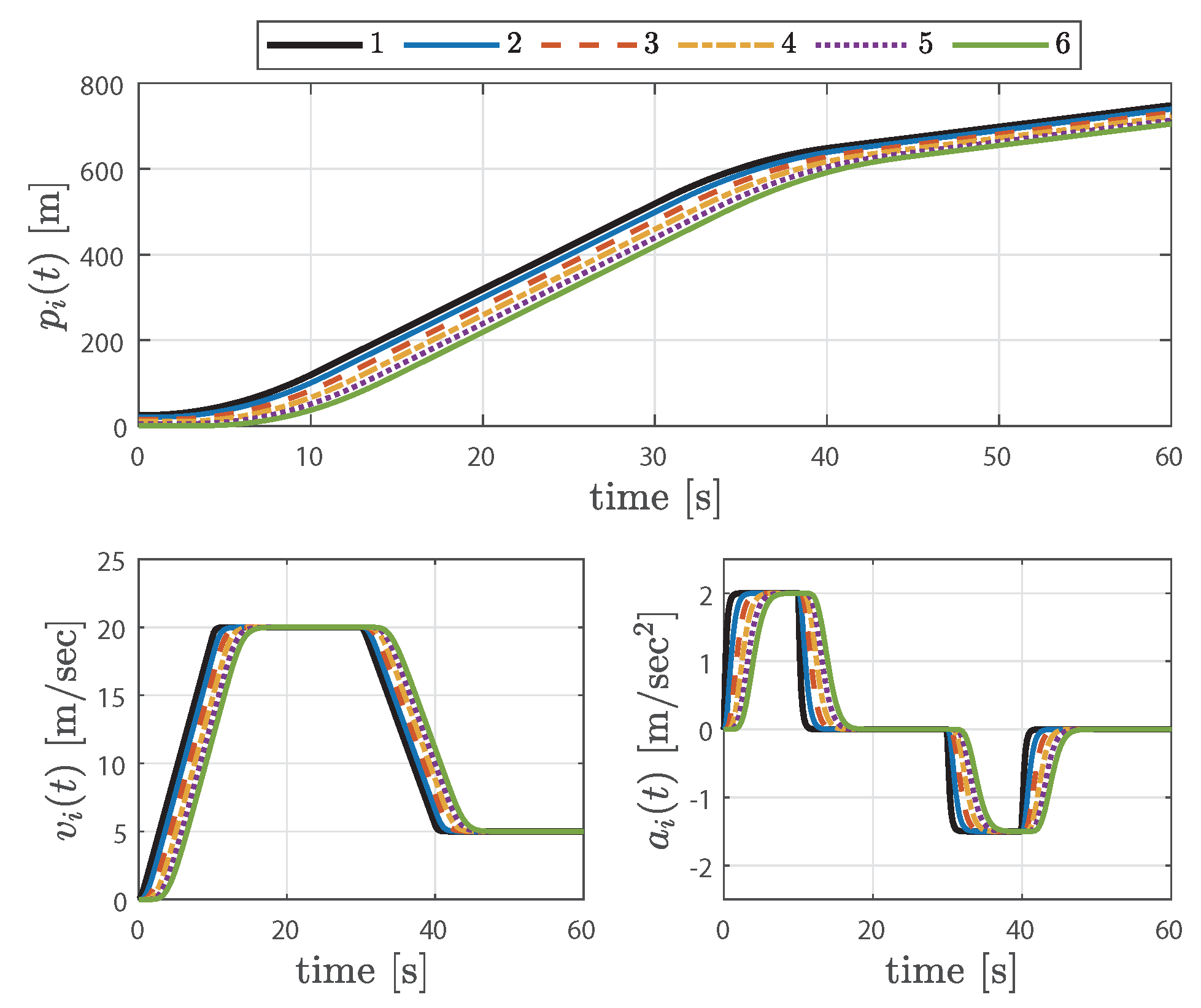
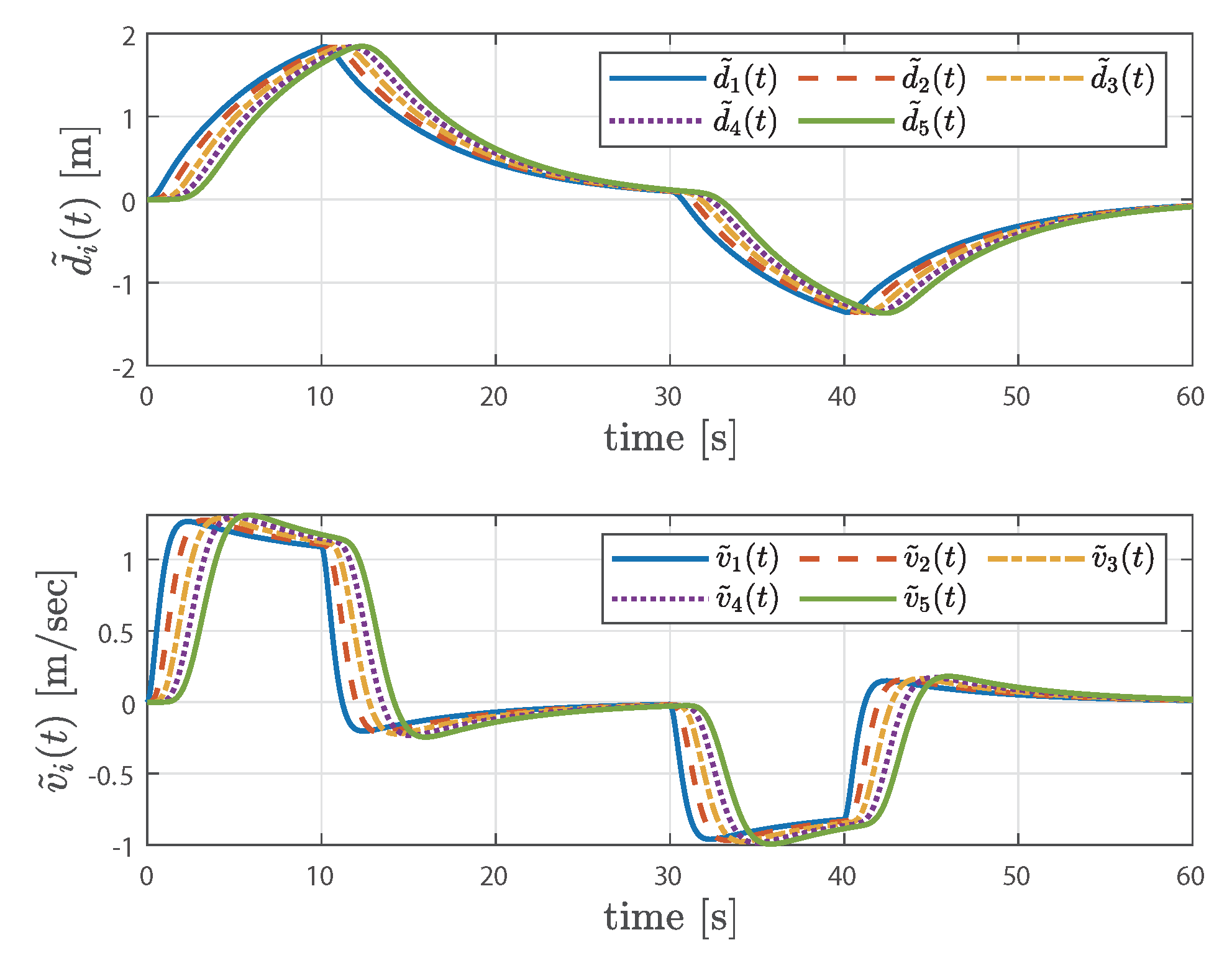
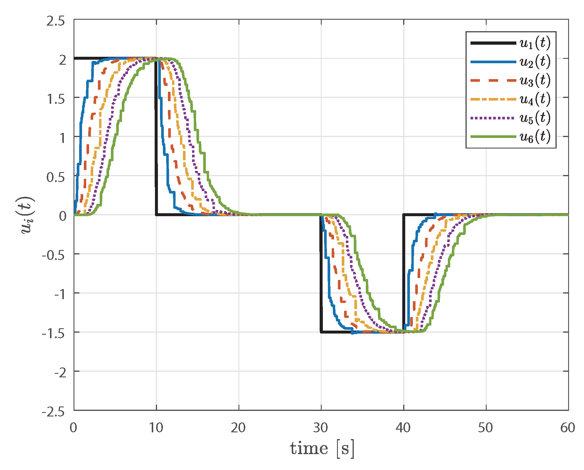
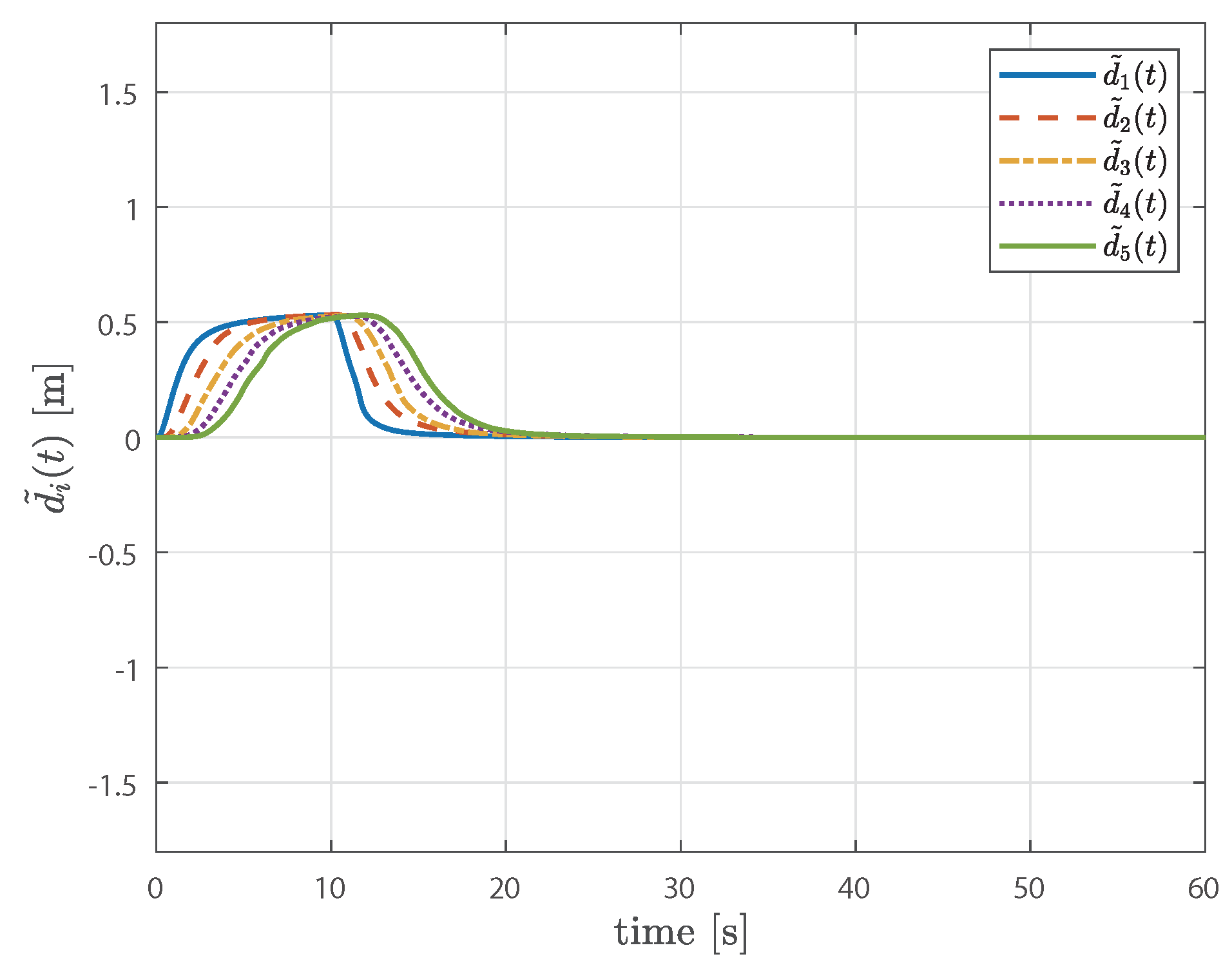
The objective of control is to ensure both individual stability, maintaining the stability of each vehicle within the platoon, and string stability, maintaining the desired spacing and speed among the vehicles, to avoid undesirable behavior and instability, ensuring the smooth operation of the platoon. In Figure 1, it can be observed that string stability is ensured for the control input u i ( t ) , satisfying the second condition described in Problem 1. Therefore, as mentioned in Remark 3, it can be seen in Figure 2 and Figure 3 that string stability is also guaranteed for v i ( t ) , a i ( t ) , and d ˜ i ( t ) . Furthermore, Figure 3 shows that Equation (5) is achieved once the preceding vehicle reaches a constant velocity. Finally, considering that these simulations are based on simulation settings that account for the communication delay τ , the conclusion that both individual stability and string stability are ensured implies the robustness of the proposed controller to communication delays.
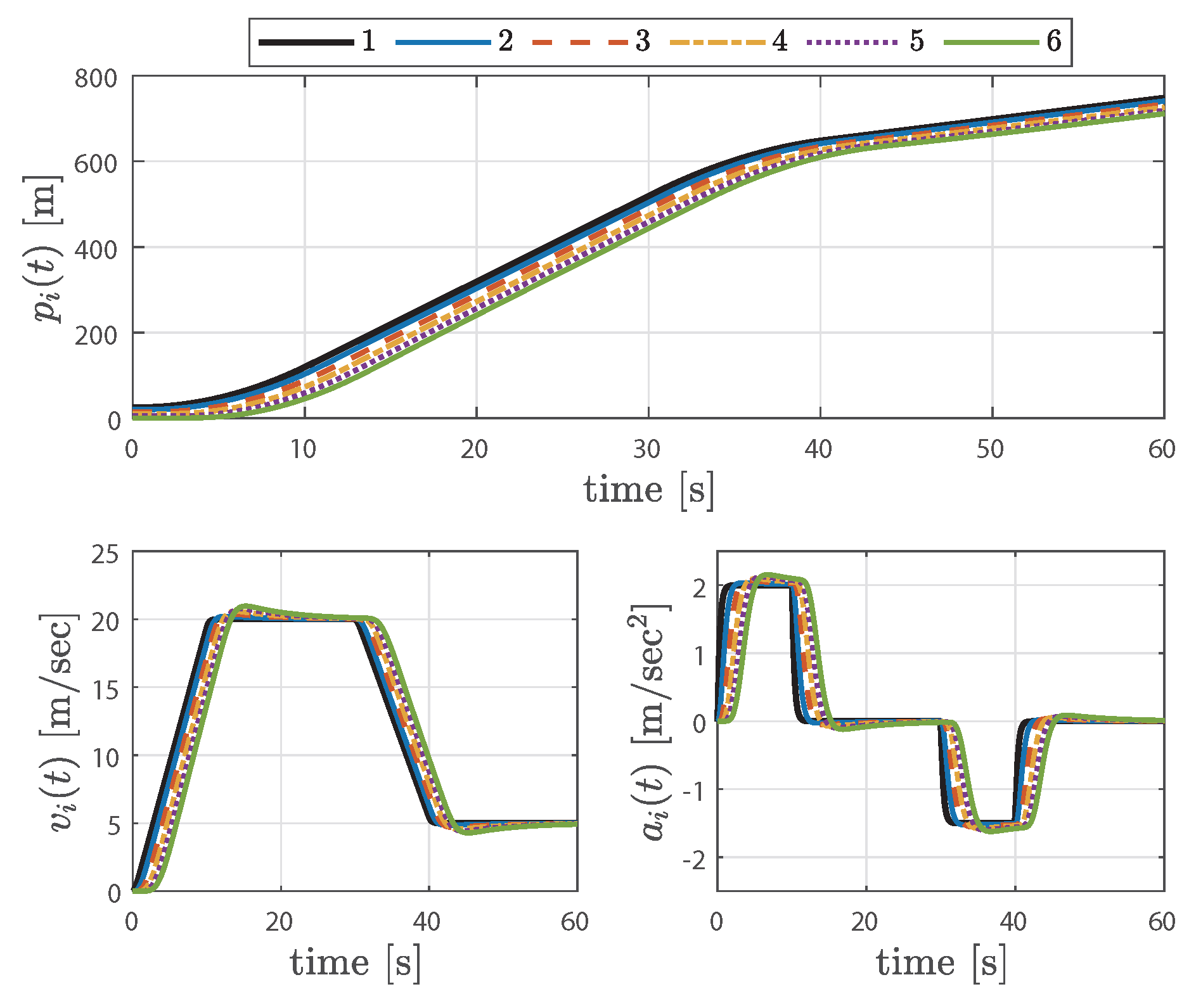
Next, to illustrate the case of string-unstable vehicle platooning, the headway time was changed to λ = 0.5 , and the simulation was repeated with the same settings. The results are shown in Figure 4, Figure 5 and Figure 6. In Figure 4, it can be observed that the control inputs amplify progressively as they go to the succeeding vehicles, indicating a lack of string stability; thus, the same results can be observed for other signals, as shown in Figure 5 and Figure 6. As the platoon size increases, it is necessary to use an appropriate headway time to ensure string stability, as amplified signals can cause serious problems for the entire system.
Additionally, we increased the sampling interval to h k [ h 1 , h 2 ] = [ 0.01 , 0.5 ] to compare the headway time, considered as a performance metric for CACC, with respect to sampling performance. In this case, in order to achieve string-stable vehicle platooning, it was necessary to increase the headway time to λ = 1.05 and change β 2 to 0.5. The relaxation of sampling performance refers to allowing for a larger sampling interval. This relaxation can lead to an increase in the conservatism of string stability performance, meaning that the headway time increases. Therefore, there is a trade-off between achieving higher levels of string stability and relaxing the sampling performance. For this case, the controller gains can be obtained as follows:
K 1 = 0.4134 1.5985 0.7923 , K 2 = 0.0017 .
The control inputs and spacing errors are shown in Figure 7 and Figure 8. In Figure 7, it can be observed that variable-sampling intervals, which were not visible in the previous figure due to a smaller sampling interval, are randomly applied within the range of h k [ h 1 , h 2 ] . Meanwhile, in Figure 8, it can be seen that d ˜ 3 ( t ) exceeds d ˜ 1 ( t ) in the boundary region, indicating a slight lack of string stability. This is due to the longer delay in responding to system changes, particularly in the boundary region where signal transitions occur, as the sampling interval increases. To address this issue, one could consider reducing the sampling interval, especially in the boundary region, but this is not covered in this study.
Lastly, a comparative analysis was conducted with a previous study. As evident in Figure 9 and Figure 10, the controller designed in [36] exhibits inferior control performance compared to the sampled-data controller proposed in this study, as it was designed in the continuous-time domain. Consequently, it can be concluded that this study could be more practically applicable to CACC utilizing sampled signals in V2V communication.

5. Conclusions

This study has proposed a sampled-data control technique, utilizing an LMI approach, to achieve string-stable vehicle platooning in the CACC system with communication delays. A sampled-data controller based on the MSC technique has been designed to improve the communication performance and reliability of CACC systems based on V2V communication. The controller design conditions have been derived through an improved LKF that utilizes partitioned sampling intervals and considers the necessary states for the CACC system configuration. The derived controller design conditions have been systematically formulated in the form of LMIs, guaranteeing both individual stability and string stability in the time domain. Finally, a simulation example has validated the feasibility and effectiveness of the proposed design technique, emphasizing its potential for practical application.

Author Contributions

Conceptualization, Y.H.J. and H.S.K.; methodology, Y.H.J.; software, Y.H.J. and H.S.K.; validation, Y.H.J. and H.S.K.; investigation, Y.H.J.; writing—original draft preparation, Y.H.J.; writing—review and editing, H.S.K. All authors have read and agreed to the published version of the manuscript.

Funding

The present research received support from the research fund of Dankook University in 2023.

Data Availability Statement

The original contributions presented in the study are included in the article, further inquiries can be directed to the corresponding author.

Conflicts of Interest

The authors declare no conflicts of interest.

References

  1. Marsden, G.; McDonald, M.; Brackstone, M. Towards an understanding of adaptive cruise control. Transp. Res. Part C-Emerg. Technol. 2001, 9, 33–51. [Google Scholar] [CrossRef]
  2. Dey, K.C.; Yan, L.; Wang, X.; Wang, Y.; Shen, H.; Chowdhury, M.; Yu, L.; Qiu, C.; Soundararaj, V. A review of communication, driver characteristics, and controls aspects of cooperative adaptive cruise control (CACC). IEEE Trans. Intell. Transp. Syst. 2015, 17, 491–509. [Google Scholar] [CrossRef]
  3. Wang, Z.; Wu, G.; Barth, M.J. A review on cooperative adaptive cruise control (CACC) systems: Architectures, controls, and applications. In Proceedings of the International Conference on Intelligent Transportation Systems (ITSC), Maui, HI, USA, 4–7 November 2018; pp. 2884–2891. [Google Scholar]
  4. Zheng, Y.; Li, S.E.; Wang, J.; Cao, D.; Li, K. Stability and scalability of homogeneous vehicular platoon: Study on the influence of information flow topologies. IEEE Trans. Intell. Transp. Syst. 2015, 17, 14–26. [Google Scholar] [CrossRef]
  5. Zheng, Y.; Li, S.E.; Li, K.; Ren, W. Platooning of connected vehicles with undirected topologies: Robustness analysis and distributed H-infinity controller synthesis. IEEE Trans. Intell. Transp. Syst. 2017, 19, 1353–1364. [Google Scholar] [CrossRef]
  6. Salvi, A.; Santini, S.; Valente, A.S. Design, analysis and performance evaluation of a third order distributed protocol for platooning in the presence of time-varying delays and switching topologies. Transp. Res. Part C-Emerg. Technol. 2017, 80, 360–383. [Google Scholar] [CrossRef]
  7. Hu, J.; Bhowmick, P.; Arvin, F.; Lanzon, A.; Lennox, B. Cooperative control of heterogeneous connected vehicle platoons: An adaptive leader-following approach. IEEE Robot. Autom. Lett. 2020, 5, 977–984. [Google Scholar] [CrossRef]
  8. Ge, X.; Han, Q.L.; Wang, J.; Zhang, X.M. Scalable and resilient platooning control of cooperative automated vehicles. IEEE Trans. Veh. Technol. 2022, 71, 3595–3608. [Google Scholar] [CrossRef]
  9. Li, Y.; Lv, Q.; Zhu, H.; Li, H.; Li, H.; Hu, S.; Yu, S.; Wang, Y. Variable time headway policy based platoon control for heterogeneous connected vehicles with external disturbances. IEEE Trans. Intell. Transp. Syst. 2022, 23, 21190–21200. [Google Scholar] [CrossRef]
  10. Cui, S.; Xue, Y.; Lv, M.; Yao, B.; Yu, B. Cooperative Constrained Control of Autonomous Vehicles with Nonuniform Input Quantization. IEEE Trans. Veh. Technol. 2022, 71, 11431–11442. [Google Scholar] [CrossRef]
  11. Zhu, P.; Jin, S.; Bu, X.; Hou, Z. Distributed Data-Driven Control for a Connected Heterogeneous Vehicle Platoon Under Quantized and Switching Topologies Communication. IEEE Trans. Veh. Technol. 2023, 72, 9796–9807. [Google Scholar] [CrossRef]
  12. Naus, G.J.; Vugts, R.P.; Ploeg, J.; Molengraft, M.J.v.; Steinbuch, M. String-stable CACC design and experimental validation: A frequency-domain approach. IEEE Trans. Veh. Technol. 2010, 59, 4268–4279. [Google Scholar] [CrossRef]
  13. Ghasemi, A.; Kazemi, R.; Azadi, S. Stable decentralized control of a platoon of vehicles with heterogeneous information feedback. IEEE Trans. Veh. Technol. 2013, 62, 4299–4308. [Google Scholar] [CrossRef]
  14. Ploeg, J.; Shukla, D.P.; Wouw, N.V.D.; Nijmeijer, H. Controller synthesis for string stability of vehicle platoons. IEEE Trans. Veh. Technol. 2013, 15, 854–865. [Google Scholar] [CrossRef]
  15. Di Bernardo, M.; Salvi, A.; Santini, S. Distributed consensus strategy for platooning of vehicles in the presence of time-varying heterogeneous communication delays. IEEE Trans. Intell. Transp. Syst. 2014, 16, 102–112. [Google Scholar] [CrossRef]
  16. Chen, J.; Liang, H.; Li, J.; Lv, Z. Connected automated vehicle platoon control with input saturation and variable time headway strategy. IEEE Trans. Intell. Transp. Syst. 2020, 22, 4929–4940. [Google Scholar] [CrossRef]
  17. Abolfazli, E.; Besselink, B.; Charalambous, T. Minimum Time Headway in Platooning Systems Under the MPF Topology for Different Wireless Communication Scenario. IEEE Trans. Intell. Transp. Syst. 2023, 24, 4377–4390. [Google Scholar] [CrossRef]
  18. Zhu, Y.; He, H.; Zhao, D. LMI-based synthesis of string-stable controller for cooperative adaptive cruise control. IEEE Trans. Intell. Transp. Syst. 2019, 21, 4516–4525. [Google Scholar] [CrossRef]
  19. Zhu, Y.; Zhao, D.; He, H. Synthesis of cooperative adaptive cruise control with feedforward strategies. IEEE Trans. Veh. Technol. 2020, 69, 3615–3627. [Google Scholar] [CrossRef]
  20. Fridman, E. A refined input delay approach to sampled-data control. Automatica 2010, 46, 421–427. [Google Scholar] [CrossRef]
  21. Bian, Y.; Zheng, Y.; Ren, W.; Li, S.E.; Wang, J.; Li, K. Reducing time headway for platooning of connected vehicles via V2V communication. Transp. Res. Part C-Emerg. Technol. 2019, 102, 87–105. [Google Scholar] [CrossRef]
  22. Bekiaris-Liberis, N. Robust String Stability and Safety of CTH Predictor-Feedback CACC. IEEE Trans. Intell. Transp. Syst. 2023, 24, 8209–8221. [Google Scholar] [CrossRef]
  23. Sharmila, V.; Rakkiyappan, R. Memory sampled-data controller design for interval type-2 fuzzy systems via polynomial-type Lyapunov–Krasovskii functional. IEEE Trans. Syst. Man Cybern. Syst. 2022, 53, 82–93. [Google Scholar] [CrossRef]
  24. Ge, C.; Park, J.H.; Hua, C.; Guan, X. Nonfragile consensus of multiagent systems based on memory sampled-data control. IEEE Trans. Syst. Man Cybern. Syst. 2018, 51, 391–399. [Google Scholar] [CrossRef]
  25. Saravanakumar, R.; Amini, A.; Datta, R.; Cao, Y. Reliable memory sampled-data consensus of multi-agent systems with nonlinear actuator faults. IEEE Trans. Circuits Syst. II-Express Briefs 2021, 69, 2201–2205. [Google Scholar] [CrossRef]
  26. Han, S.; Zhong, Q.; Cui, L.; Shi, K.; Cai, X.; Kwon, O.M. Extended dissipativity analysis for T–S fuzzy systems based on reliable memory control and aperiodic sampled-data method. J. Frankl. Inst. 2022, 359, 2156–2175. [Google Scholar] [CrossRef]
  27. Cao, Y.; Udhayakumar, K.; Veerakumari, K.P.; Rakkiyappan, R. Memory sampled data control for switched-type neural networks and its application in image secure communications. Math. Comput. Simul. 2022, 201, 564–587. [Google Scholar] [CrossRef]
  28. Zhu, Y.; Wu, J.; Su, H. V2V-based cooperative control of uncertain, disturbed and constrained nonlinear CAVs platoon. IEEE Trans. Intell. Transp. Syst. 2020, 23, 1796–1806. [Google Scholar] [CrossRef]
  29. Ploeg, J.; Wouw, N.V.D.; Nijmeijer, H. Lp string stability of cascaded systems: Application to vehicle platooning. IEEE Trans. Control Syst. Technol. 2013, 22, 786–793. [Google Scholar] [CrossRef]
  30. Zhu, X.L.; Wang, Y. Stabilization for sampled-data neural-network-based control systems. IEEE Trans. Syst. Man Cybern. B Cybern. 2010, 41, 210–221. [Google Scholar]
  31. Liu, K.; Fridman, E. Wirtinger’s inequality and Lyapunov-based sampled-data stabilization. Automatica 2012, 48, 102–108. [Google Scholar] [CrossRef]
  32. Lee, T.H.; Park, J.H. New methods of fuzzy sampled-data control for stabilization of chaotic systems. IEEE Trans. Syst. Man Cybern. Syst. 2017, 48, 2026–2034. [Google Scholar] [CrossRef]
  33. Wang, X.; Park, J.H.; Yang, H.; Zhao, G.; Zhong, S. An improved fuzzy sampled-data control to stabilization of T–S fuzzy systems with state delays. IEEE Trans. Cybern. 2019, 50, 3125–3135. [Google Scholar] [CrossRef] [PubMed]
  34. Lofberg, J. YALMIP: A toolbox for modeling and optimization in MATLAB. In Proceedings of the 2004 IEEE International Conference on Robotics and Automation, Taipei, Taiwan, 2–4 September 2004; pp. 284–289. [Google Scholar]
  35. Andersen, E.D.; Andersen, K.D. The MOSEK interior point optimizer for linear programming: An implementation of the homogeneous algorithm. In High Performance Optimization; Springer: Berlin/Heidelberg, Germany, 2000; pp. 197–232. [Google Scholar]
  36. Lee, S.; Kim, H.S. A linear matrix inequality-based relaxed time-delay platooning controller design for multiple autonomous vehicles. J. Inst. Contr. Robot. Syst. 2023, 29, 841–846. (In Korean) [Google Scholar] [CrossRef]
Figure 1. The time responses of the control inputs achieved through string-stable vehicle platooning.
Machines 12 00165 g001
Figure 2. The state trajectories of the position, velocity, and acceleration achieved through string-stable vehicle platooning.
Machines 12 00165 g002
Figure 3. The time responses of the spacing error and velocity error achieved through string-stable vehicle platooning.
Machines 12 00165 g003
Figure 4. The time responses of the control inputs achieved through string-unstable vehicle platooning.
Machines 12 00165 g004
Figure 5. The state trajectories of the position, velocity, and acceleration achieved through string-unstable vehicle platooning.
Machines 12 00165 g005
Figure 6. The time responses of the spacing error and velocity error achieved through string-unstable vehicle platooning.
Machines 12 00165 g006
Figure 7. The time responses of the control inputs with ( h 1 , h 2 ) = ( 0.01 , 0.5 ) .
Machines 12 00165 g007
Figure 8. The time responses of the spacing error with ( h 1 , h 2 ) = ( 0.01 , 0.5 ) .
Machines 12 00165 g008
Figure 9. The time responses of the spacing error with ( h 1 , h 2 ) = ( 0.1 , 0.3 ) , using Theorem 2.
Machines 12 00165 g009
Figure 10. The time responses of the spacing error with ( h 1 , h 2 ) = ( 0.1 , 0.3 ) , using the controller designed in [36].
Machines 12 00165 g010
Disclaimer/Publisher’s Note: The statements, opinions and data contained in all publications are solely those of the individual author(s) and contributor(s) and not of MDPI and/or the editor(s). MDPI and/or the editor(s) disclaim responsibility for any injury to people or property resulting from any ideas, methods, instructions or products referred to in the content.