Article

Proposal for Hemiplegic Thumb Rehabilitation Device Based on Repetitive Facilitation Exercise

1
Department of Electronic Control Engineering, National Institute of Technology, Kagoshima College, Kagoshima 899-5193, Japan
2
Graduate School of Science and Engineering, Kagoshima University, Kagoshima 890-0065, Japan
*
Author to whom correspondence should be addressed.
Machines 2024, 12(12), 920; https://doi.org/10.3390/machines12120920
Submission received: 12 November 2024 / Revised: 9 December 2024 / Accepted: 12 December 2024 / Published: 16 December 2024
(This article belongs to the Special Issue Design and Application of Medical and Rehabilitation Robots)

Abstract

In this paper, we propose a thumb rehabilitation device based on the concept of Repetitive Facilitation Exercise (RFE) therapy. Our device only uses rapid passive stretching to the extensor muscle to induce a stretch reflex as a facilitative stimulation. RFE, a proven rehabilitation method, promotes neural pathway recovery through repetitive voluntary movements facilitated by passive stimulation. We proposed a simple mechanism capable of performing flexion/extension and palmar adduction/abduction RFE training movements using only a single motor and a single link, without a tapping mechanism. Our results demonstrate that the proposed control method can induce a stretch reflex in the desired muscle through rapid adduction/flexion passive stretching and facilitate active abduction/extension motion.

1. Introduction

The World Health Organization estimates that 15 million people worldwide suffer a stroke each year, of which 5 million die and another 5 million are left permanently disabled [1]. Stroke patients often suffer from sequelae such as hemiplegia, even if their life is saved by treatment. Hemiplegia is paralysis that affects only one side of the body, and it is caused by brain damage after a stroke. The thumb, with its 5-DoF [2,3], is essential for ADL tasks such as pinching and grasping, as well as for modern activities like smartphone operation [4]. Therefore, motor function recovery of the thumb contributes greatly to the improvement of ADL and improves quality of life (QOL).
Repetitive Facilitation Exercise (RFE) therapy has recently been recognized as an effective rehabilitation method for hemiplegia [5,6,7,8]. RFE promotes neural reconstruction by repeatedly facilitating voluntary movements through passive stimulation, such as stretch reflexes, electrical stimulation, vibration stimulation. Inducing voluntary movements requires advanced techniques and significant time to acquire the skill. Furthermore, the burden on therapists is also heavy, because RFE is performed on a one-to-one basis.
There is much research about hand rehabilitation robots [9]; however, there is little research relating to thumb rehabilitation robots. Other studies on thumb rehabilitation devices include the “AI-integrated EMG-driven robot hand”, which has already been shown to be effective in clinical studies [10]. This robot detects patients’ intentions to perform finger extension and flexion based on the EMG activities of three forearm muscles. However, this exoskeleton robot requires the attachment of electrodes, making it less user-friendly in terms of wearability. Additionally, while RFE enables the separation of synergistic movements crucial for hemiplegic rehabilitation, this robot lacks such functionality. Moreover, the active motion is limited to flexion and extension. Another notable study is Schabowsky et al.’s work on the Hand Exoskeleton Rehabilitation Robot [11]. This device is a rehabilitation robot designed to provide a full range of motion for all fingers, including the degrees of freedom for palmar abduction/adduction of the thumb. Functional improvements in the fingers, including the thumb, were observed in five chronic stroke patients. However, it lacks the capability to provide facilitative stimulation, such as RFE.
As mentioned in the background above, we have been developing a robotic rehabilitation device with the following aims: establishing effective rehabilitation of thumb motor function based on the RFE principle, promoting the adoption of RFE, and reducing the burden on therapists. In manual training, therapists use “tapping” to stretch the target tendons and induce stretch reflexes, promoting voluntary movement. Tapping is facilitative stimulation which induces the stretch reflex by tapping a target tendon to stretch the target muscle. However, if this method is robotized in its entirety, many actuators are required and the mechanism becomes complicated; therefore, the cost will increase. In addition, it is difficult to make a design that helps patients feel secure [12,13,14]. Furthermore, training is more effective when the patient can watch the target limb [15]. Therefore, it is important to make a simple design and mechanism which does not distract the patient’s attention to their own motion. In previous research, it was suggested that rapid passive stretching could be used as an alternative to the tapping stimulation [14]. Rapid passive stretching is an RFE technique in which the target joint is rapidly passively flexed to rapidly stretch the extensor muscles, eliciting a stretch reflex in the extensor muscles and providing a facilitatory stimulus to the extensor muscles. Moreover, previous studies have shown the effectiveness of RFE-based rehabilitation devices for fingers, forearms, and knees in patients with hemiplegia [12,13,16,17].
In this paper, we analyze the manual RFE techniques for thumb flexion/extension and palmar adduction/abduction, as described in Section 2. Secondly, in Section 3, we propose specifications and designs of the RFE thumb rehabilitation device, which only uses rapid passive stretching as a facilitative stimulation for the thumb. The proposed device can facilitate and assist in voluntary movement of the hemiplegic thumb using a simple mechanism consisting of a single motor and a single link. In Section 4, we propose the control method enabling RFE for the thumb. In Section 5, we show that the proposed thumb passive flexion/palmar adduction could induce a stretch reflex in the desired muscle. We also demonstrate that the proposed device enables active thumb extension/palmar abduction through EMG measurements.

2. Analysis of Manual RFE for Thumbs

2.1. Principle of RFE

RFE is an exercise therapy developed to recover from motility disturbance in hemiplegic upper limbs. The aim of RFE is to reconstruct and strengthen a target neural circuit, especially the pyramidal tract. It is due to a synergistic effect of performance of the desired motion by facilitation of intensive repetition. For the patient to perform a desired motion, the therapist synchronizes motion facilitation with the patient’s own efforts to attempt to move, using oral instruction and asking the patient to watch the limb being trained. The therapist employs stretch reflexes through rapid passive stretching and the skin–muscle reflex by tapping. The key point is to repeat the movement about 100 times within a few minutes [15].

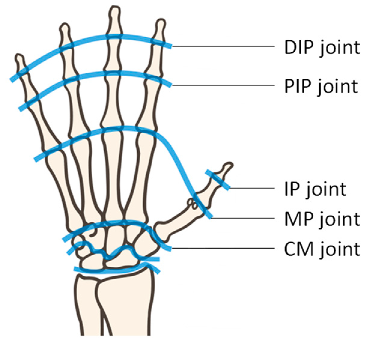
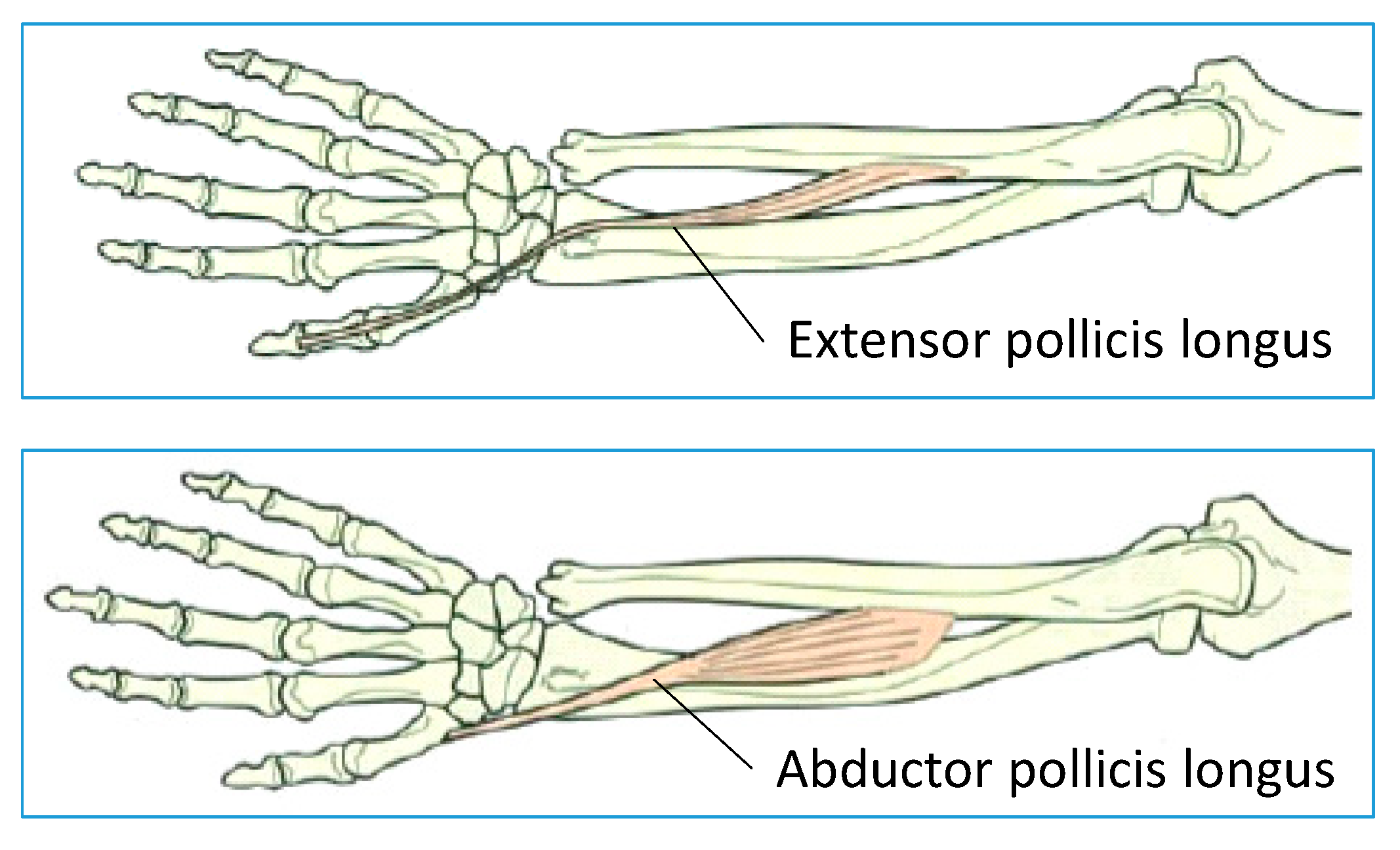
2.2. Movement of Thumb

The movements and joints of the thumb are different from those of other fingers, as shown in Figure 1 and Figure 2. Thumb movements are roughly divided into flexion/extension and palmar adduction/abduction. The DoF of the thumb is higher than that of the other fingers, because palmar adduction/abduction, flexion/extension, or rotation can be performed by the metacarpophalangeal (MP) joint or the carpometacarpal (CM) joint, as shown in Figure 1 [2,3]. The thumb enables us to perform complicated movements by combining these two degrees of freedom (DoF). A target action by the trainee’s own intention is referred to as an active movement (voluntary movement), while a movement by external manipulation is referred to as a passive movement.

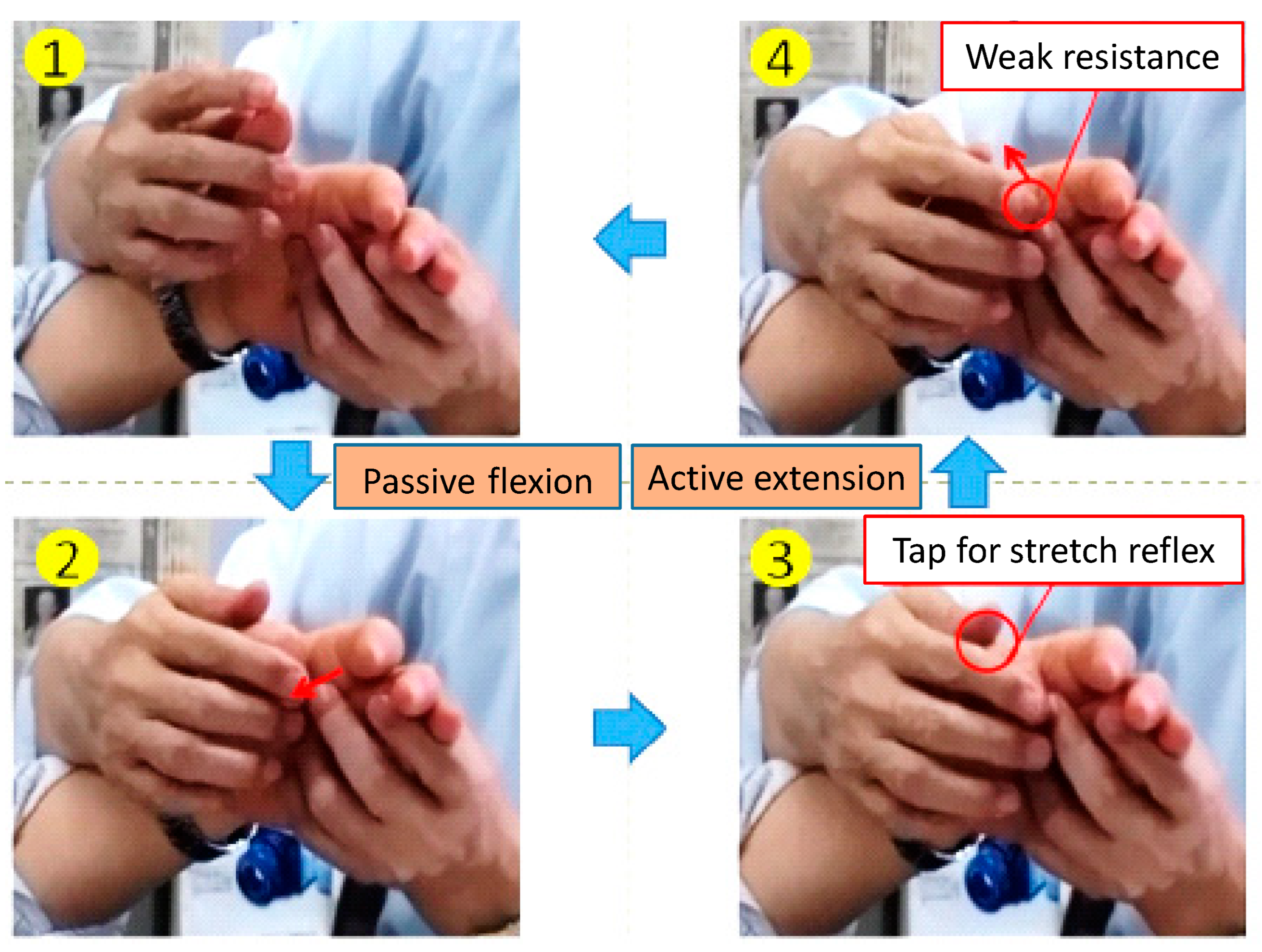
2.3. Manual RFE for Thumb Flexion/Extension

We describe a manual RFE method for thumbs below [5,6,7,8,15]. Firstly, a therapist passively flexes the thumb of a patient. Secondly, the therapist gives a sign of starting the desired training motion with their voice, in addition to a simultaneous tapping stimulation on the MP joint. The tapping stimulation induces a stretch reflex that facilitates active thumb extension. Therefore, effective neurorehabilitation is expected because the desired training movement performed by voluntary movement of the patient’s intention is facilitated by the stretch reflex. In these training movements, it is important that the patient looks at their thumb while training in order for the visual feedback to be effective. Figure 3 shows a procedure of manual training for thumb flexion/extension. We describe the details of the procedure of manual RFE for thumb flexion/extension below [15]:
  • The therapist passively flexes the hemiplegic thumb;
  • The therapist finishes the passive flexion at the maximal flexion position to induce the stretch reflex of the extensor muscle. Thus, the extensor muscles become under muscle tone;
  • The therapist gives a signal and taps the MP joint to induce a stretch reflex, facilitating active extension;
  • The therapist continues to give slight resistance force against the active extension of the thumb to maintain the tension of the extensor muscle;
  • The therapist repeats the above procedure 100 times.

2.4. Manual RFE for Thumb Palmar Adduction/Abduction

The therapist performs the palmar adduction training movement passively and palmar abduction actively, similarly to the case of thumb flexion/extension. At that moment, the therapist gives a tapping stimulation at the outside of the thenar before palmar abduction to induce the stretch reflex of the abductor muscle. Thus, voluntary palmar abduction is facilitated. Figure 4 shows the procedure of manual RFE for thumb palmar adduction/abduction. We describe the details of the procedure of manual RFE for thumb palmar adduction/abduction below [15]:
  • The therapist passively performs palmar adduction on the hemiplegic thumb;
  • The therapist finishes the passive palmar adduction at the maximal adduction position to induce the stretch reflex of the palmar abduction muscle; thus, the abductor muscles become under muscle tone;
  • The therapist signals and taps the thenar to induce a stretch reflex, enabling active palmar abduction by the patient;
  • The therapist continues to give a slight resistance force against the active palmar abduction of the thumb to maintain the tension of the abductor muscle.
  • The therapist repeats the above procedure 100 times.

3. Proposed Rehabilitation Device for Hemiplegic Thumb

We describe the required specifications for developing a rehabilitation device based on the treatment theory of RFE for hemiplegic thumbs. High safety and functionality, as well as low costs, are important for practical realization.

3.1. Device Specifications

These following specifications are needed to perform thumb flexion or palmar adduction:
  • The device needs to induce stretch reflexes of a target muscle;
  • The device needs to track the active motion facilitated by the stretch reflex; in addition, the tracking motion must force slight resistance;
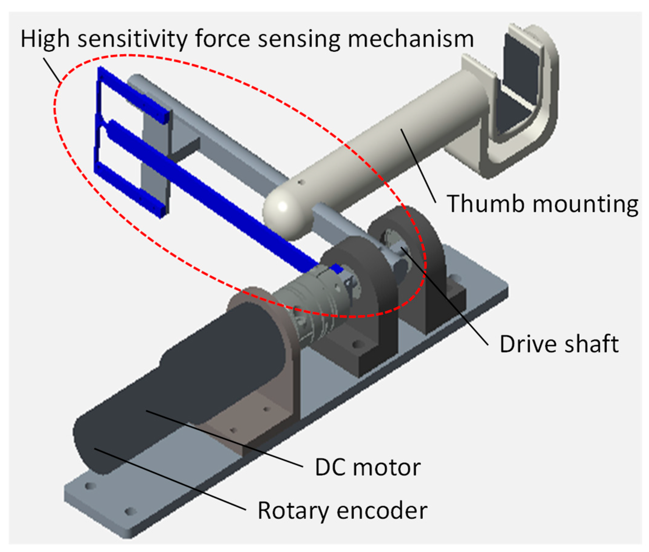
  • The device needs a high-sensitivity force sensing mechanism to measure the force of active motion;
  • Patients can watch the target thumb;
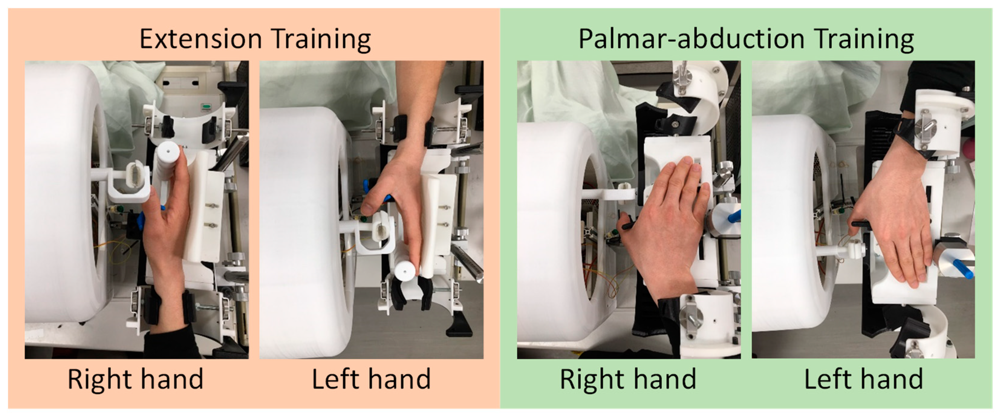
  • The device needs to support training for both the left and right hands with a single device;
  • Patients need to be able to easily wear the device while ensuring safety;
  • The device needs to be a single-link mechanism owing to low costs.

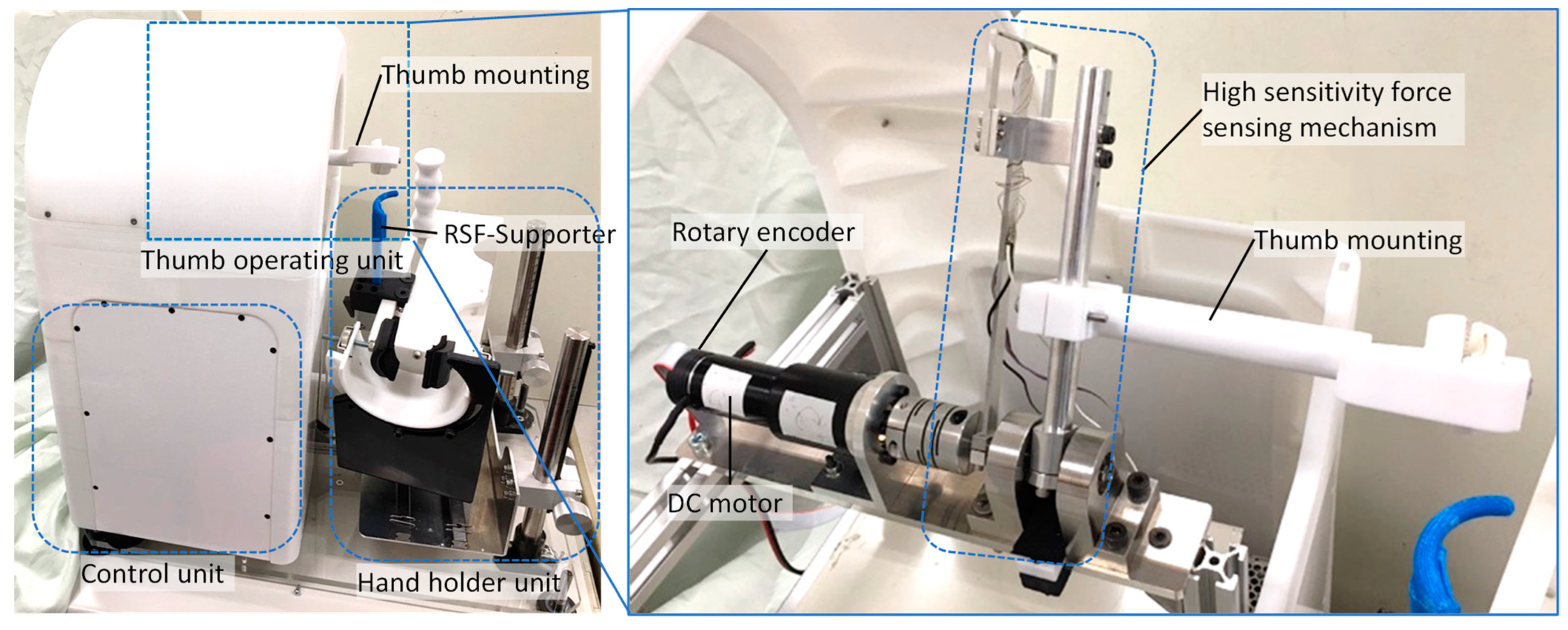
3.2. Proposed Device

Figure 5 shows the proposed devices based on the above specifications. The proposed device can perform both thumb flexion/extension and palmar adduction/abduction motion with only one device. Users can use the proposed device facing in the front or back direction to train both the right and left hands. In Figure 5, the user sits facing in front of the device while the user trains the right hand. On the other hand, the user sits facing on the back of the device while the user trains the left hand. The electric circuit parts and mechanisms of the device are covered with plastic covers to prevent users from feeling fear. In addition, the user cannot touch the drive units from a safety perspective. However, only training parts are designed outside of the cover so that users can watch their own training motion. The proposed device is designed to be satisfactory in terms of training quality, safety, and perceived quality, as mentioned above.

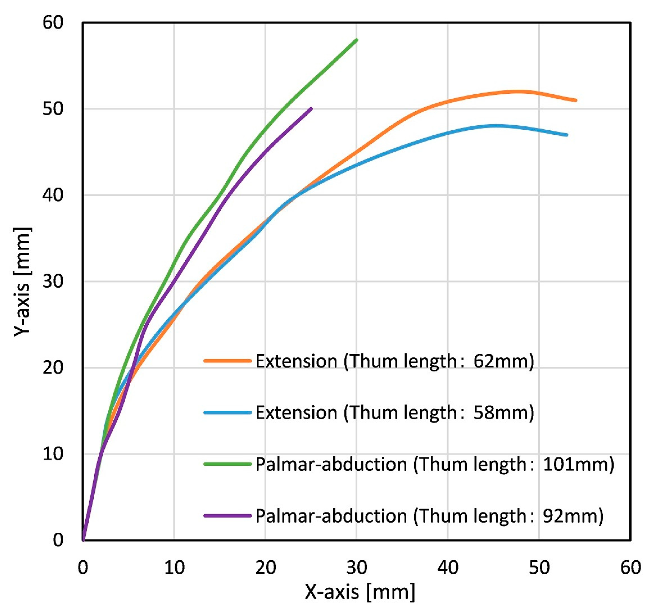
3.3. Trajectory of Thumb

The training movement for thumb extension is 3-DoF due to the IP joint, MP joint, and CM joint. The thumb movement can be limited to only the movement of the IP joint and MP joint to perform training with rapid passive stretching using a single rotary actuator due to the DoF of the CM joint being restrained with the supporter. We name this supporter the RSF-Supporter (Rapid Stretch Facilitation Supporter), which promotes rapid stretching of the target muscle (Figure 5). The thumb extension movement can be approximated as 1-DoF motion with only the MP joint because the length from the IP joint to the fingertip of the thumb is short.
The training movement for thumb palmar abduction is 2-DoF movement due to the MP joint and CM joint. However, the thumb palmar abduction movement can be approximated as 1-DoF motion with only the CM joint because the displacement of the MP joint is slighter than that of the CM joint.
Figure 6 shows two subjects’ examples of the trajectory of the thumb fingertip during extension and palmar abduction, as measured by the rehabilitation device with a 2-DoF parallel link mechanism developed in previous studies. The trajectory when the thumb moves from the maximum flexion position as the origin to the maximum extension position is plotted in XY coordinates. Here, in the case of extension, the thumb length is defined as the length from the MP joint to the fingertip. In the case of palmar abduction, the thumb length is defined as the length from the CM joint to the fingertip. The graphs for palmar abduction illustrate an approximate circular motion centered on the CM joint. Therefore, we considered that thumb extension/palmar abduction RFE training movements can be performed with only the 1-DoF mechanism. Furthermore, we proposed a simple rehabilitation device which has a 1-DoF actuator.

3.4. Driving Mechanism of Thumb Training

We proposed the driving mechanism for thumb extension/palmar abduction RFE training due to the trajectory of the thumb, as mentioned above. We showed that thumb movements can be approximated as a rotary motion of 1-DoF. Thus, the trajectory of thumb rotary movement needs to coincide with that of the rotary mechanism. Therefore, the mechanism of the proposed device enables a change in the posture of the training hand so that it coincides with the axis of rotation. Moreover, the proposed device enables the training of both the right and left hand via bilateral symmetry training movements. Figure 7 shows the procedure of thumb extension and palmar abduction training of the right hand. The left part of Figure 7 shows the case of extension training; the right part of Figure 7 shows the case of palmar abduction training. In addition, the palmar abduction rotation direction is opposite of the case of thumb extension. The training flow of the left thumb is the same as the case of the right thumb (Figure 8); however, the hand direction and rotation direction of the driving mechanism are the opposite of the right thumb. A detailed explanation is as follows:
  • The user places the palm vertically/horizontally on the table and aligns the rotary axis of the MP/CM joint with the rotary axis of the driving mechanism;
  • The device bends the training thumb to its pre-measured maximum flexion/palmar adduction angle with the circular movement;
  • After the training thumb finger reaches the maximum flexion/palmar adduction angle, the device performs extension/palmar abduction with the circular movement;
  • The device performs extension/palmar abduction until the training thumb returns to its initial posture with the circular movement.

3.5. Thumb Operating Unit

Figure 9 shows the thumb operating unit. The driving force of the motor is transmitted by the driveshaft, and the driveshaft rotates the thumb operating unit. The thumb mounting part and the thumb are mounted by Velcro fasteners. Owing to this mounting method, the thumb easily detaches even if the device malfunctions in case of emergency so that safety can be given redundancy. In addition, the finger mounting part has a rounded shape made of nylon resin, and is designed to confer a sense of security to the patient. A high-sensitivity force-sensing mechanism is incorporated in the thumb operating unit as a torque sensor. Strain gauges are attached to the elastic deformation part of the torque sensor. Details of the force-sensing principle are described in the next section.

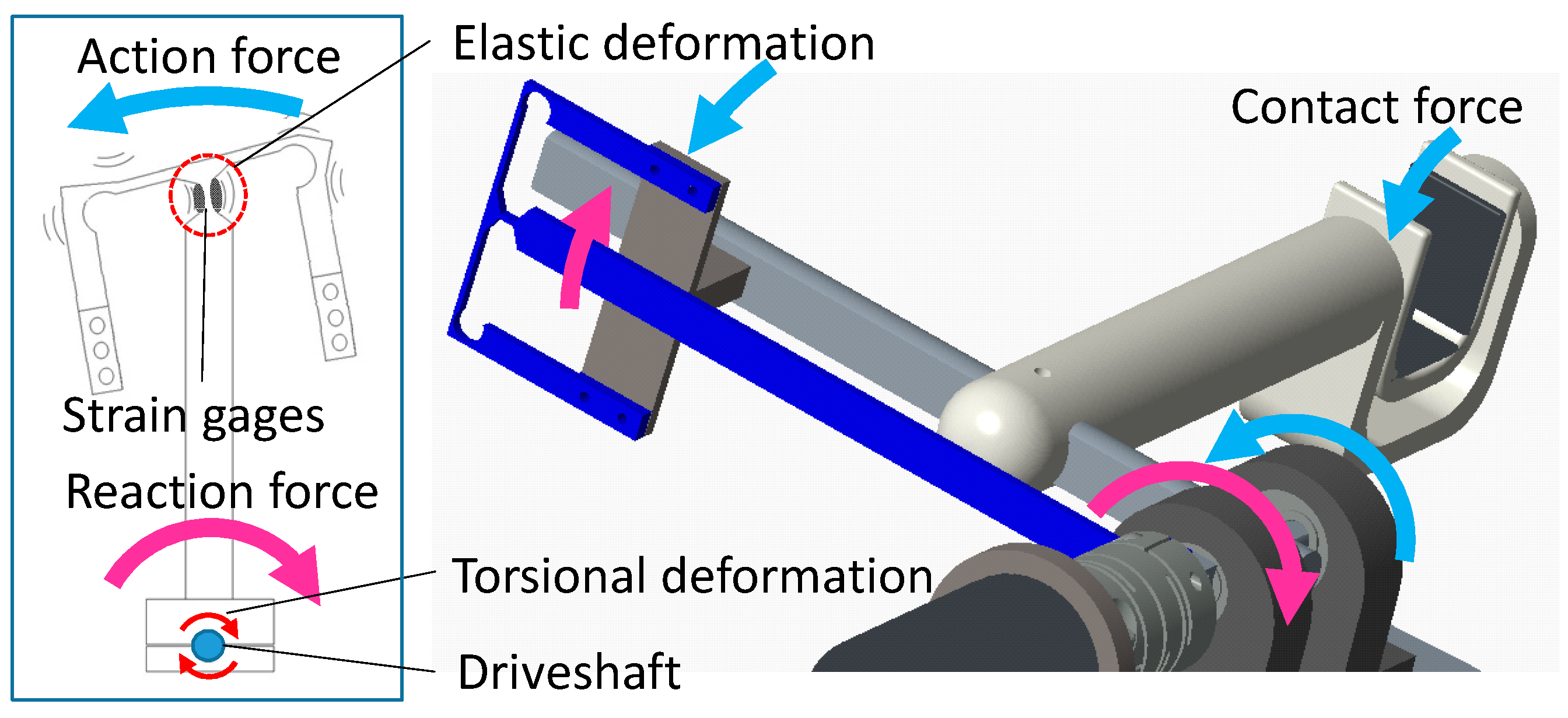
3.6. The High-Sensitivity Force-Sensing Mechanism

Because forces exerted by a hemiplegic thumb are very small, the force sensor is required to have high sensitivity to detect minute forces. Therefore, we applied a torque sensor to this device, which uses a strain expansion mechanism capable of sensing with high sensitivity [18]. Figure 10 shows that strain gauges are attached to the constricted portion of the strain expansion mechanism. The two-gauge measurement method is used for torque sensors. The two-gauge measurement method is temperature-compensated, eliminates the temperature effects on the lead wires, and eliminates compressive or tensile strain. Therefore, it is a suitable method for measuring bending strain. When a contact force between the thumb and finger mounting part acts on the drive shaft, torsional deformation of the driveshaft is enlarged due to the length of the elastic body of the sensor, and the constricted portion of the sensor is elastically deformed. The deformation is read by the change in electric resistance of the strain gauge. Therefore, this device can measure the moment of the thumb with high sensitivity.

4. Control Method

In this research, we adopted rapid passive stretching instead of tapping as the facilitative stimulus. The training thumb was fixed to the device using Velcro fasteners for safety. The training procedure is shown in Figure 7.

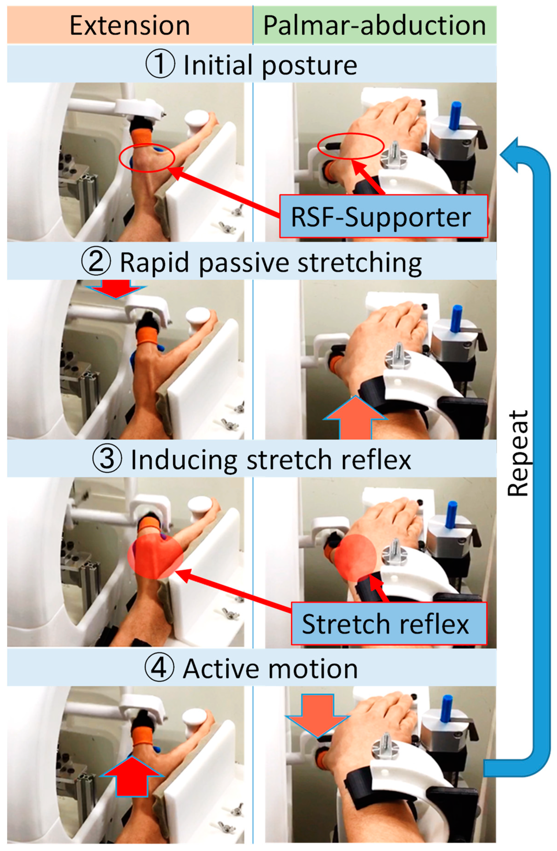
4.1. Training Method for Thumb Extension/Palmar Abduction Using Proposed Device

Details of the training method for thumb extension using proposed device are described below:
  • The driving part of the fingertip of the device controls the flexion/palmar adduction of the thumb passively;
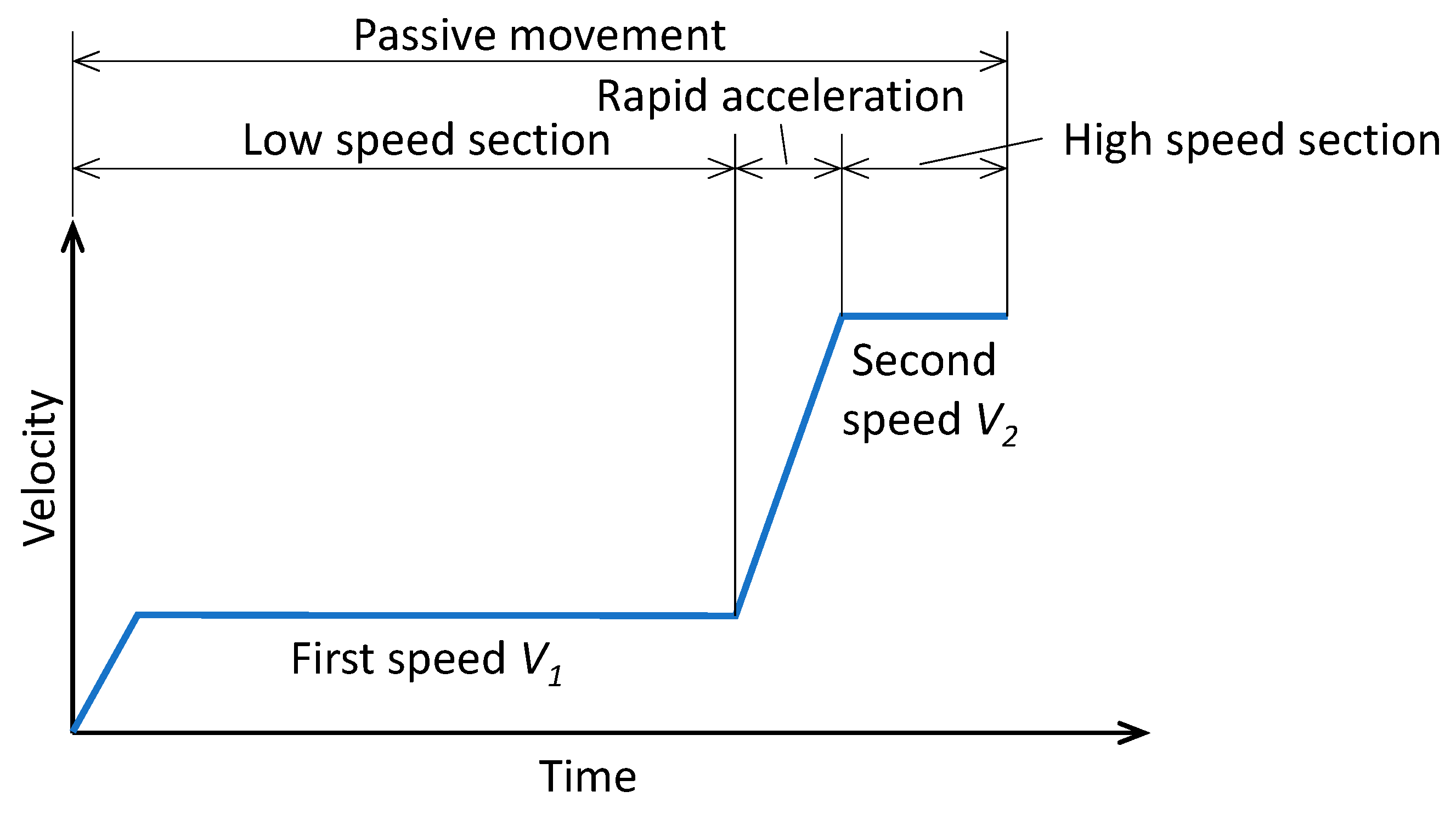
  • The device accelerates flexion/palmar adduction before reaching the maximal position, increasing motion velocity from the first to the second speed (Figure 11);
  • That acceleration facilitates the stretch reflex of the extensor muscle by supporting the MP joint/thumb root with RSF-Supporter at the same time as rapid passive flexion/adduction;
  • Stretch reflex increases the excitement of the target nerve tract and facilitates voluntary active extension/palmar abduction. The device follows the active motion by measuring the intention of the active motion via the torque sensor. Moreover, the device performs extension/palmar abduction while giving slight resistance to that active motion before returning the initial posture so that the device provides kinesthesia and keeps the stretch reflex.
The device repeats this procedure a preset number of times.

4.2. Proposal of Resistance-Accompanying Cooperation Control

In the case of patient’s active exercise, the therapist provides weak resistance in a opposite direction to the patient’s movement to maintain muscle tone and assist the motion by sensing the intent of the patient’s motion. To perform active exercise operations, Resistance-Accompanying Cooperation Control (RACC) [16,19] is adopted to follow the patient’s active motion. The RACC is a control method to assist with the training movement by sensing the force of the training thumb while providing resistance to the paralysis thumb to yield a constant impedance characteristic [12]. The motor is controlled by speed control. A virtual compliance control formula is used as a control formula for determining the target speed. The impedance equation for the torque of the training thumb T is expressed by the following equation [16]:
T = I θ ¨ + C θ ˙ + K θ
Here, θ represents the present angle of the device drive unit, I represents the virtual inertia, C is the virtual viscosity, and K represents the virtual elasticity. Discretizing Equation (1) and setting K = 0 , the following equation is obtained:
T n = I θ ˙ n θ ˙ n 1 t + C θ ˙ n 1
Furthermore, the following equation is obtained by solving Equation (2) for θ ˙ n :
θ ˙ n = t I T n C θ ˙ n 1 + θ ˙ n 1
Due to the above equation, it is possible to generate a target angular velocity by measuring the torque T and the past angular velocity of the training thumb.

4.3. Tuning Control for the Stretch Reflex Time Lag

In Figure 7, operations 2–3 are controlled by speed control, since the training motions are passive exercises. On the other hand, operation 4 is controlled by RACC, since the training motion is active. Between operations 3 and 4, the thumb motion changes from passive movement to active movement. Inevitably, there is time lag before the stretch reflex of the target muscle occurs. Therefore, it was necessary to introduce a waiting time between the end of the passive movement and the start of the active movement. The waiting time must be well-tuned to synchronize with the start time of active movement.

5. Verification of the Proposed Device

We confirmed the induction of stretch reflex and RACC assistance via surface EMG measurement while training using the proposed device. The EMG was RMS-processed. The subject was an able-bodied volunteer. Figure 12 shows the agonist muscles for thumb extension and palmar abduction. The extensor muscle of the thumb is the extensor pollicis longus (EPL), and the agonist muscle of palmar abduction of the thumb is the abductor pollicis longus (APL). We measured the surface EMG of the EPL or APL muscle during the training.

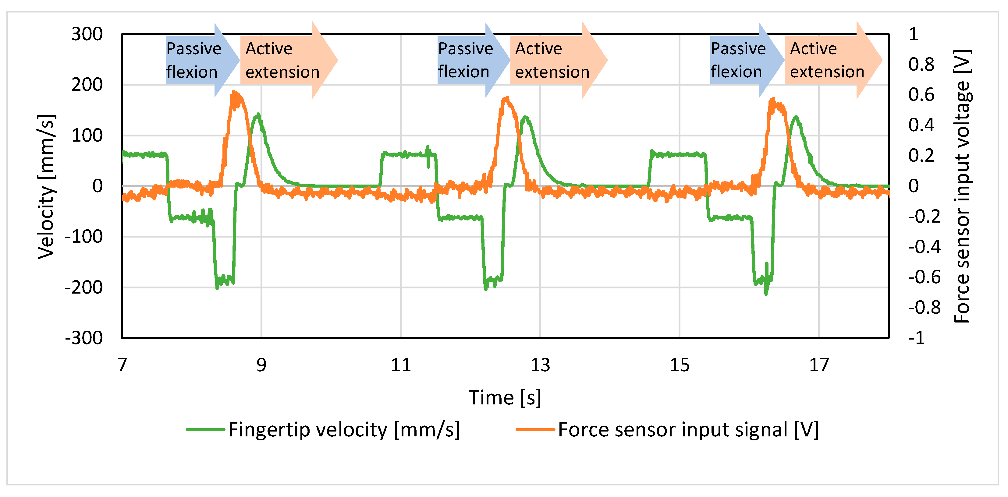
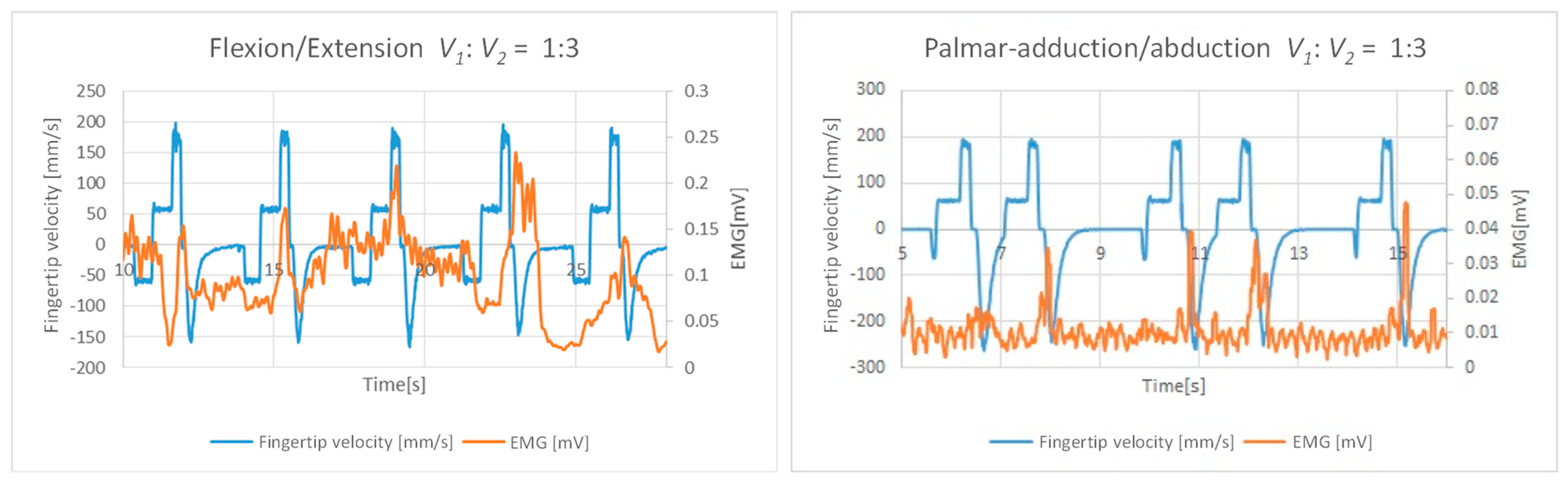
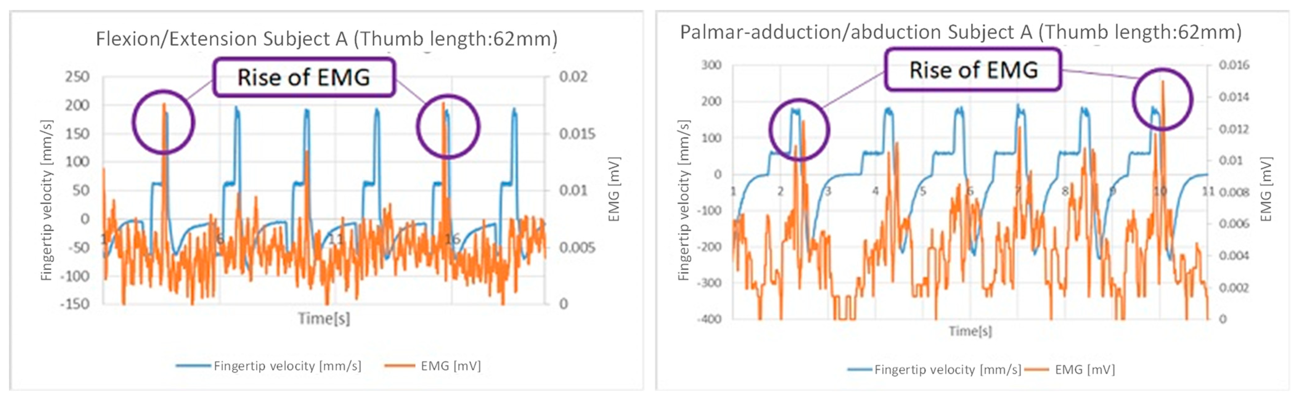
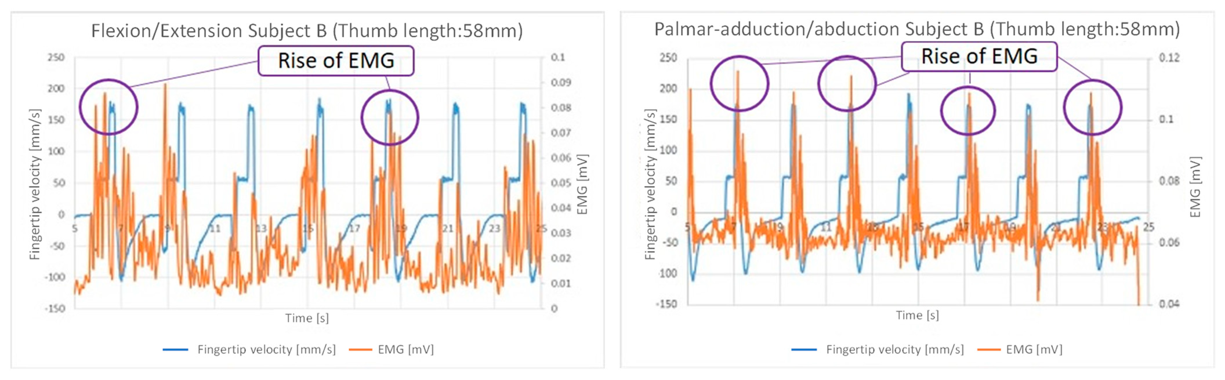
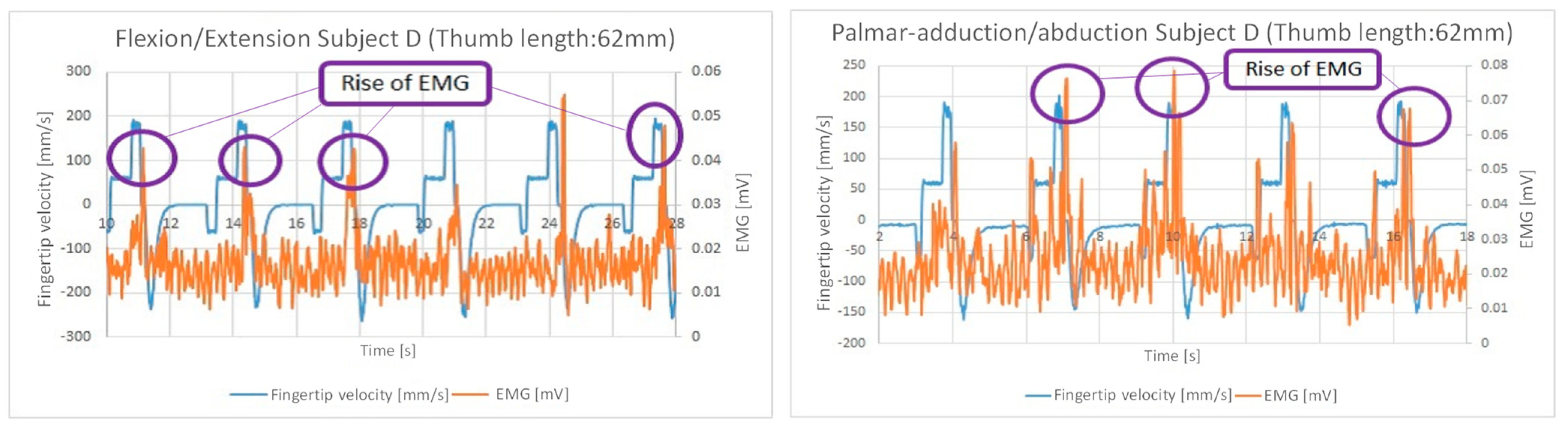
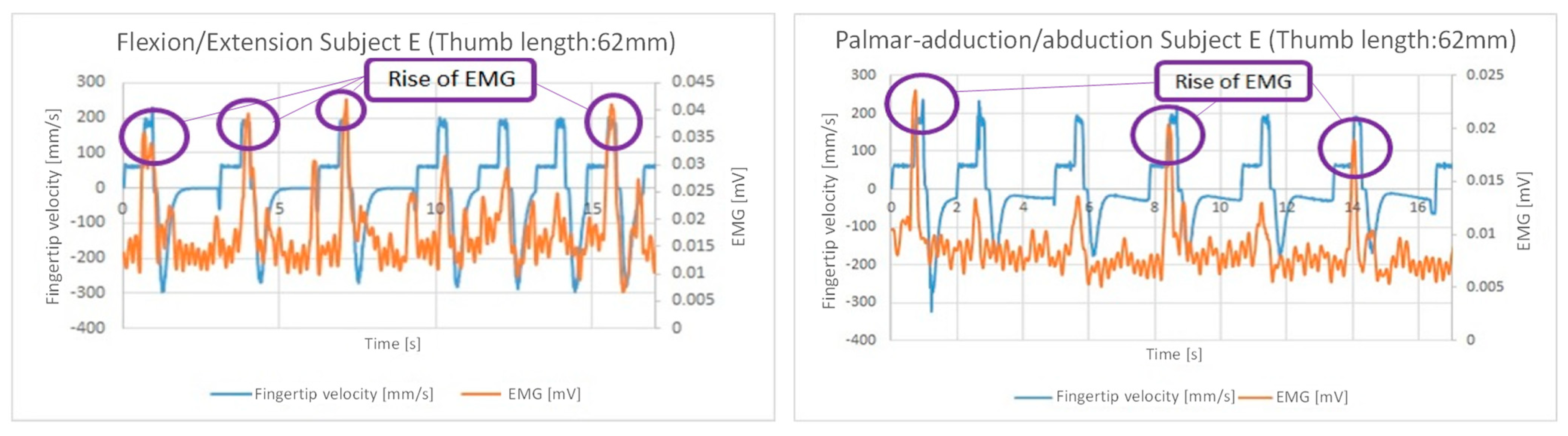
5.1. Verification of Relations of Fingertip Velocity and EMG

Figure 13 shows the graphs of fingertip velocity and EMG of the EPL muscle in a training motion of thumb extension with rapid passive stretching using the proposed device. EMG was measured under passive conditions to confirm stretch reflex induction. The first speed circled with a green line is the first motion to start passive flexion movement. The second speed circled with the red line is the accelerated thumb flexion motion. As shown in the purple circle, the stretch reflex of the EPL muscle is induced by its stretching and facilitated by acceleration from the first speed to the second speed. In this case, in the active movement mode, this stretch reflex facilitates active thumb extension; the thumb is extended to the initial position with only assistance of RACC. If the thumb does not return to the initial position after a certain period, the thumb is moved passively to the initial position. Next, the passive flexion and active extension are repeated.
Figure 14 shows the graphs of fingertip velocity and force sensor input signal in thumb extension training. This graph shows that the high-sensitivity force-sensing mechanism is sensitive enough to perform the active extension movement, enabling control by the RACC.
Therefore, we can see the induction of a stretch reflex by passive stretching and rapid stretching of the target muscle and the assistance of active movement by the RACC, as shown in Figure 13. It is suggested that there is a possibility of performing the RFE training movement using the proposed device.

5.2. Verification of Stretch Reflex Induction Using the Proposed Device

EMG was measured under passive conditions to confirm stretch reflex induction. We show the results of training with the speed difference between the first speed V1 and second speed V2 in Figure 15 and Figure 16 to confirm the induction of stretch reflex caused by rapid passive stretching. Figure 15 shows that little stretch reflexes were induced in the case without rapid passive stretching. In contrast, Figure 16 shows that stretch reflexes were induced in the case of rapid passive stretching. Thus, these results show the effectiveness of rapid passive stretching with the difference between V1 and V2.

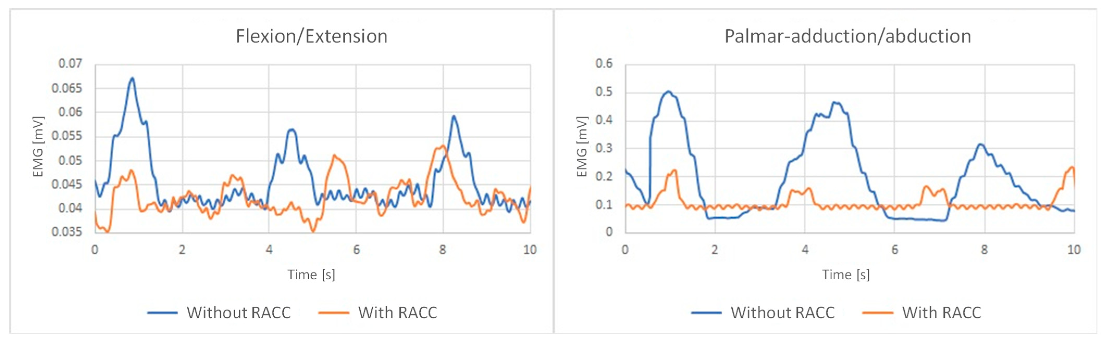
5.3. Verification of RACC Assistance

EMG measurements during training were performed along with voluntary muscle tensioning to confirm RACC’s assistance in active movement. We show the EMG measurements results of training with RACC and without RACC in Figure 17. The EMG of the EPL/APL muscle with RACC during the active movement was smaller than without RACC for both extension and palmar abduction. Thus, these results show the effectiveness of RACC’s assistance in active movement.

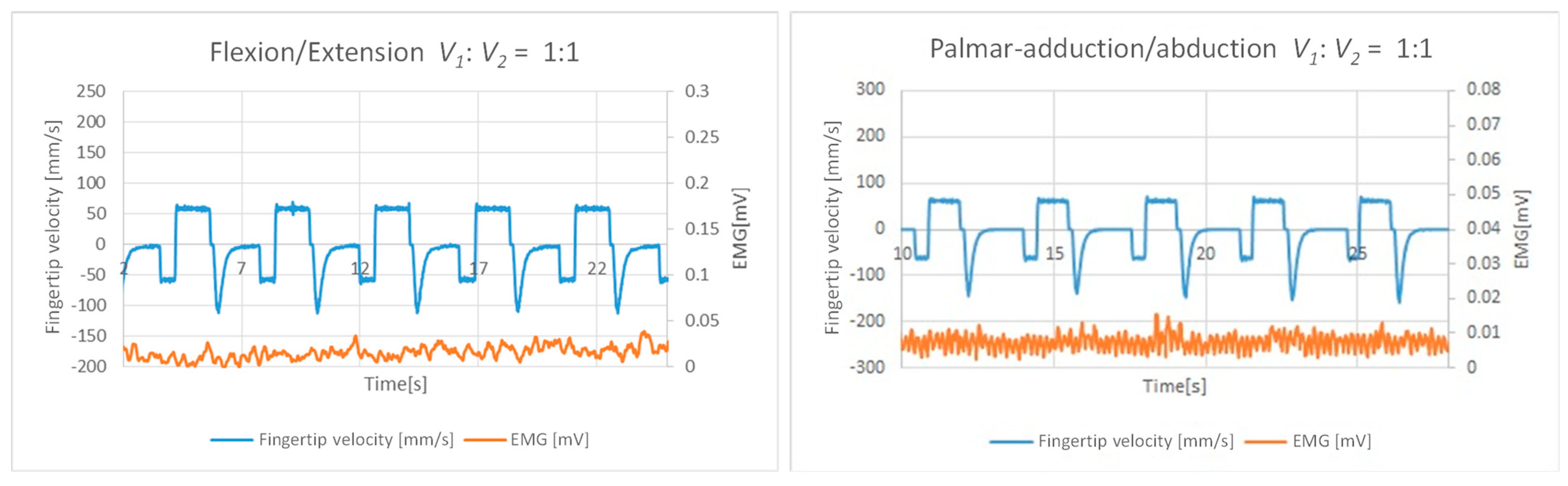
5.4. Verification Experiments of Thumb Extension/Palmar Abduction Training

Figure 18, Figure 19, Figure 20, Figure 21 and Figure 22 show the results of thumb extension training using the proposed device in five able-bodied subjects. EMG was measured under passive conditions to confirm stretch reflex induction. These graphs show the EMG rise of the EPL/APL muscle; thus, they demonstrate that stretch reflexes of the EPL/APL muscle were induced by thumb extension/palmar abduction training with rapid passive stretching using the proposed device. There are portions where the fingertip velocity is approximately −50 mm/s before the passive movement. These are operations to passively return to the initial position if the initial position has not been reached during active movement. In palmar abduction training, the subjects, except for subject D, performed abduction to the starting position despite being in a condition without voluntary muscle tensioning. It is considered that the RACC in active movement assisted the abduction movement caused by the stretch reflex of the APL muscle. These results suggest that even hemiplegic patients with weak voluntary movement may be able to perform the RFE training movement.

6. Conclusions

In this paper, we analyzed the manual RFE techniques for thumb flexion/extension and palmar adduction/abduction. Secondly, we proposed specifications for a rehabilitation device based on the RFE principle for hemiplegic thumb, which uses only rapid passive stretching as a facilitative stimulation. Moreover, we verified that the trajectory of thumb extension and palmar abduction can be approximated as a 1-DoF circular motion. Therefore, we designed a thumb operating unit with a simple 1-DoF mechanism with only one actuator and a high-sensitivity force-sensing mechanism. In addition, we proposed control methods which perform rapid passive stretching to induce stretch reflex in the EPL/APL muscle and performed RACC to assist in active extension/palmar abduction movement.
The verification experiment’s results suggest that rapid passive stretching (in the case that the second speed is three times the first speed) can induce the stretch reflex of the EPL/APL muscle. Furthermore, we showed the effectiveness of RACC assistance in active thumb extension/palmar abduction by comparing EMG with/without RACC. Finally, the experimental results of five able-bodied subjects demonstrate that stretch reflexes of EPL/APL muscle were induced by rapid passive stretching using the proposed device, and the RACC in active movement assisted the abduction movement caused by the stretch reflex of the APL muscle. These results suggest that even hemiplegic patients with weak voluntary movement may be able to perform the RFE training movement.
Previous studies on hemiplegic patients using RFE-based rehabilitation devices for fingers, forearms, and knees have shown significant effects, and similar effects can be expected for the thumb rehabilitation device proposed in this study. Future prospects include the need to demonstrate both short-term and long-term effects in clinical studies involving hemiplegic patients.

7. Patents

Yu, Yong; Maeda, Katsuya; Kawahira, Kazumi, and Shimodozono, Megumi; “Hemiplegic thumb function recovery training device”; Japanese Patent Number: JP6308400B2.
Yu, Yong; Maeda, Katsuya; Kawahira, Kazumi, and Shimodozono, Megumi; “Training device for hemiplegic thumb function recovery”; International Publication Number: WO2014/126097A1.

Author Contributions

Conceptualization, Y.Y.; methodology, Y.Y., Y.T. and K.T.; software, Y.T.; validation, Y.Y., Y.T. and K.T.; formal analysis, Y.Y., Y.T. and K.T.; investigation, Y.T. and K.T.; resources, Y.Y.; data curation, Y.T.; writing—original draft preparation, Y.T. and K.T.; writing—review and editing, K.T. and Y.Y.; visualization, Y.T. and K.T.; supervision, Y.Y.; project administration, Y.Y.; funding acquisition, Y.Y. All authors have read and agreed to the published version of the manuscript.

Funding

This work was supported by Adaptable and Seamless Technology transfer Program through Target-driven R&D (A-STEP) from Japan Science and Technology Agency (JST) Grant Number JST-PROJECT-12102840.

Institutional Review Board Statement

The study was conducted in accordance with the Declaration of Helsinki and approved by Ethics Committee of National Institute of Technology, Kagoshima College (KR24-4, 25 September 2024).

Informed Consent Statement

Informed consent was obtained from all subjects involved in the study.

Data Availability Statement

The data presented in this study are available on request from the corresponding author. The data are not publicly available due to the perspective of personal information protection.

Acknowledgments

The authors would like to thank all subjects involved in the study. We are also grateful to the anonymous reviewers of this article for their very constructive contributions.

Conflicts of Interest

The funders had no role in the design of the study; in the collection, analyses, or interpretation of data; in the writing of the manuscript; or in the decision to publish the results.

References

  1. WHO. Stroke, Cerebrovascular Accident. 2024. Available online: https://www.emro.who.int/health-topics/stroke-cerebrovascular-accident/index.html (accessed on 18 June 2024).
  2. Kapandji, I.A.; Owerko, C.; Anderson, A. The Physiology of the Joints—Volume 1: The Upper Limb, 5th ed.; Churchill Livingstone: London, UK, 1982; pp. 251–290. [Google Scholar]
  3. Rahman, M.A.; Al-Jumaily, A. Design and Development of a Hand Exoskeleton for Rehabilitation Following Stroke. Procedia Eng. 2012, 41, 1028–1034. [Google Scholar] [CrossRef]
  4. Xiong, J.; Muraki, S. An ergonomics study of thumb movements on smartphone touch screen. Ergonomics 2014, 57, 943–955. [Google Scholar] [CrossRef] [PubMed]
  5. Kawahira, K.; Shimodozono, M.; Etoh, S.; Kamada, K.; Noma, T.; Tanaka, N. Effects of Intensive Repetition of a New Facilitation Technique on Motor Functional Recovery of the Hemiplegic Upper Limb and Hand. Brain Inj. 2010, 24, 1202–1213. [Google Scholar] [CrossRef] [PubMed]
  6. Kawahira, K.; Shimodozono, M.; Ogata, A.; Tanaka, N. Addition of Intensive Repetition of Facilitation Exercise to Multidisciplinary Rehabilitation Promotes Motor Functional Recovery of the Hemiplegic Lower Limb. J. Rehabil. Med. 2004, 36, 159–164. [Google Scholar] [CrossRef] [PubMed]
  7. Kawahira, K.; Noma, T.; Iiyama, J.; Etoh, S.; Ogata, A.; Shimodozono, M. Improvements in Limb Kinetic Apraxia by Repetition of a Newly Designed Facilitation Exercise in a Patient with Corticobasal Degeneration. Int. J. Rehabil. Res. 2009, 32, 178–183. [Google Scholar] [CrossRef] [PubMed]
  8. Shimodozono, M.; Noma, T.; Nomoto, Y.; Hisamatsu, N.; Kamada, K.; Miyata, R.; Matsumoto, S.; Ogata, A.; Etoh, S.; Basford, J.R.; et al. Benefits of a Repetitive Facilitative Exercise Program for the Upper Paretic Extremity after Subacute Stroke: A Randomized Controlled Trial. Neurorehabilit. Neural Repair 2013, 27, 296–305. [Google Scholar] [CrossRef] [PubMed]
  9. Yue, Z.; Zhang, X.; Wang, J. Hand Rehabilitation Robotics on Poststroke Motor Recovery. Behav. Neurol. 2017, 2017, 3908135. [Google Scholar] [CrossRef]
  10. Murakami, Y.; Honaga, K.; Kono, H.; Haruyama, K.; Yamaguchi, T.; Tani, M.; Isayama, R.; Takakura, T.; Tanuma, A.; Hatori, K.; et al. New Artificial Intelligence-Integrated Electromyography-Driven Robot Hand for Upper Extremity Rehabilitation of Patients With Stroke: A Randomized, Controlled Trial. Neurorehabilit. Neural Repair 2023, 37, 298–306. [Google Scholar] [CrossRef] [PubMed]
  11. Schabowsky, C.N.; Godfrey, S.B.; Holley, R.J.; Lum, P.S. Development and pilot testing of HEXORR: Hand EXOskeleton Rehabilitation Robot. J. NeuroEng. Rehabil. 2010, 7, 36. [Google Scholar] [CrossRef] [PubMed]
  12. Yu, Y.; Iwashita, H.; Kawahira, K.; Hayashi, R. Development of Functional Recovery Training Device for Hemiplegic Fingers with Finger-expansion Facilitation Exercise by Stretch Reflex. Trans. Soc. Instrum. Control Eng. 2012, 48, 413–422. [Google Scholar] [CrossRef]
  13. Yu, Y.; Iwashita, H.; Kawahira, K.; Hayashi, R. Development of Rehabilitation Device for Hemiplegic Fingers by Finger-Expansion Facilitation Exercise with Stretch Reflex. In Proceedings of the 2013 IEEE International Conference on Robotics and Biomimetics, Shenzhen, China, 12–14 December 2013; pp. 1317–1323. [Google Scholar]
  14. Yu, Y.; Tanda, Y.; Kimoto, Y.; Taniguchi, K.; Kawahira, K.; Shimodozono, M. Research on Hemiplegic Thumb Rehabilitation Device Using Repetitive Stimulus by Rapid Accelerative Facilitation. In Proceedings of the 23th Robotics Symposia, Shizuoka, Japan, 14–15 March 2018; pp. 172–175. (In Japanese). [Google Scholar]
  15. Kawahira, K.; Shimodozono, M.; Noma, T. Exercise Therapy for Recovery from Hemiplegia: Theory and Practice of Repetitive Facilitative Exercise; Springer Nature: Singapore, 2022; pp. 3–46. [Google Scholar]
  16. Yu, Y.; Nakanishi, Y.; Kawahira, K.; Shimodozono, M.; Hayashi, R. Production of effective stretch reflex by a pronation and supination function recovery training device for hemiplegic forearms. In Proceedings of the 2015 IEEE International Conference on Robotics and Biomimetics (ROBIO2015), Zhuhai, China, 6–9 December 2015; pp. 150–157. [Google Scholar]
  17. Yu, Y.; Kodama, M.; Matsuwaki, H.; Matsumoto, S.; Taniguchi, K.; Yamanaka, H.; Fukuda, I.; Shimodozono, M.; Kawahira, K. Development of Functional Recovery Training Device for Hemiplegic Knee Flexion Based on Repetitive Facilitation Exercise. J. Robot. Soc. Jpn. 2017, 35, 239–248. (In Japanese) [Google Scholar] [CrossRef]
  18. Yu, Y.; Ishitsuka, T.; Tsujio, S. Torque Sensing of Finger Joint Using Strain-Deformation Expansion Mechanism. J. Robot. Soc. Jpn. 2002, 20, 526–538. [Google Scholar] [CrossRef]
  19. Yu, Y.; Kodama, M.; Matsuwaki, H.; Taniguchi, K.; Matsumoto, S.; Yamanaka, H.; Fukuda, I.; Shimodozono, M.; Kawahira, K. Research of Rehabilitation Device for Hemiplegic Knee Flexion Based on Repetitive Facilitation Exercise. Intell. Robot. Appl. 2016, 9835, 158–167. [Google Scholar]
Figure 1. Finger joints.
Machines 12 00920 g001
Figure 2. Thumb flexion/extension (left) and palmar adduction/abduction (right).
Machines 12 00920 g002
Figure 3. Manual RFE method for thumb flexion/extension. The numbers 1 to 4 in the diagram correspond to the procedure numbers above explanations.
Machines 12 00920 g003
Figure 4. Manual RFE method for thumb palmar adduction/abduction. The numbers 1 to 4 in the diagram correspond to the procedure numbers above explanations.
Machines 12 00920 g004
Figure 5. Proposed device. Left picture is the device with a cover; right picture is an enlarged view of the thumb operating unit without a cover.
Machines 12 00920 g005
Figure 6. Trajectory of thumb extension and palmar abduction.
Machines 12 00920 g006
Figure 7. Training procedures of thumb extension/palmar abduction.
Machines 12 00920 g007
Figure 8. Training posture of thumb extension/palmar abduction.
Machines 12 00920 g008
Figure 9. Mechanism of thumb operating unit.
Machines 12 00920 g009
Figure 10. The high-sensitivity force-sensing mechanism.
Machines 12 00920 g010
Figure 11. Control method of passive movement.
Machines 12 00920 g011
Figure 12. Muscles of thumb extension and palmar abduction.
Machines 12 00920 g012
Figure 13. Relations between fingertip velocity and EMG of APL muscle in thumb extension training. The EMG was RMS-processed.
Machines 12 00920 g013
Figure 14. Fingertip velocity and force sensor input signal in thumb extension training.
Machines 12 00920 g014
Figure 15. Results of EMG in thumb extension (left), palmar abduction (right), and training without rapid passive stretching (V1:V2 = 1:1).
Machines 12 00920 g015
Figure 16. Results of EMG in thumb extension (left), palmar abduction (right), and training with rapid passive stretching (V1:V2 = 1:3).
Machines 12 00920 g016
Figure 17. Results of EMG of the EPL/APL muscle in thumb extension (left) and palmar abduction (right) training with/without RACC.
Machines 12 00920 g017
Figure 18. Result of EMG in thumb extension (left) and palmar abduction (right) training in subject A.
Machines 12 00920 g018
Figure 19. Result of EMG in thumb extension (left) and palmar abduction (right) training in subject B.
Machines 12 00920 g019
Figure 20. Result of EMG in thumb extension (left) and palmar abduction (right) training in subject C.
Machines 12 00920 g020
Figure 21. Result of EMG in thumb extension (left) and palmar abduction (right) training in subject D.
Machines 12 00920 g021
Figure 22. Result of EMG in thumb extension (left) and palmar abduction (right) training in subject E.
Machines 12 00920 g022
Disclaimer/Publisher’s Note: The statements, opinions and data contained in all publications are solely those of the individual author(s) and contributor(s) and not of MDPI and/or the editor(s). MDPI and/or the editor(s) disclaim responsibility for any injury to people or property resulting from any ideas, methods, instructions or products referred to in the content.

