Article

Prediction of Fretting Wear Lifetime of a Coated System

School of Aerospace and Mechanical Engineering, Korea Aerospace University, 76 Hanggongdaehak-ro, Deogyang-gu, Goyang-si 412-791, Gyeonggi-do, Republic of Korea
Machines 2024, 12(12), 910; https://doi.org/10.3390/machines12120910
Submission received: 12 November 2024 / Revised: 29 November 2024 / Accepted: 2 December 2024 / Published: 11 December 2024
(This article belongs to the Special Issue Design and Characterization of Engineered Bearing Surfaces)

Abstract

:
This article proposes a model of predicting the fretting wear lifetime of a low-friction coating. The proposed model incorporates multiple factors that influence the fretting wear damage of coatings: the imposed contact load, imposed average velocity, coating hardness, and initial surface roughness of counterparts. The fretting wear lifetime of coatings, defined as the number of cycles critical to friction coefficient evolution, was collected from the literature. For the purpose of identifying parameters in the model, experimental fretting wear lifetime data were analyzed. The results show that the fretting wear lifetime of a coating can be described by an inverse power law regarding the contact load, imposed average velocity, and initial surface roughness of counterparts. In contrast, the fretting wear lifetime of a coating was observed to increase with increased coating hardness. It was observed that the exponents of the inverse power law varied with respect to the type of coating. The proposed fretting wear lifetime model enables the prediction of coating lifetime under various fretting conditions.

1. Introduction

Fretting wear is defined as material removal resulting from fine reciprocal sliding between two contacting bodies [1,2]. Fretting wear damage is observed in various mechanical components, including aerospace gas turbine dovetail connections [3], biomedical total hip prostheses [4], nuclear fuel rod–support interfaces [5], and automotive connectors [6,7]. Contact conditions and working conditions have a great influence on fretting wear damage. In order to minimize fretting wear damage, low-friction coatings are applied to contact surfaces [8]. However, degradation of the coating inevitably occurs across multiple fretting cycles. After a critical number of fretting cycles, the coefficient of kinetic friction (COF) begins to increase rapidly. The fretting wear lifetime of a coating is often determined by the COF evolution [9,10,11]. Kim and Korsunsky [9] defined the lifetime of a coating as the number of fretting cycles that it takes for the measured COF to reach the value observed at points of metal-to-metal contact. In another study, Langlade et al. [10] proposed that the fretting wear lifetime of a coating ends at the fretting cycle when the COF becomes three times greater than the initial COF value. Kim [11] studied worn surfaces according to the frictional force of an electro-deposited coating. The fretting wear lifetime of an electro-deposited coating was set at the fretting cycle when the average frictional force exceeded the upper control limit of statistical process control. In this case, the upper control limit indicated that the frictional force became statistically unstable after a steady state.
A variety of factors determine the COF evolution of a low-friction coating in a gross slip regime. Bill [12] reviewed factors influencing fretting wear and classified them into three categories: contact conditions, environmental conditions, and material properties and behavior. The contact conditions included imposed contact load, displacement amplitude, and frequency of motion. The environmental conditions were atmosphere, relative humidity, and temperature. Other researchers investigated the influence of the factors on the COF evolution of a coated system [13,14,15,16,17,18,19]. Jun and Kim [13] identified the influence of the contact load on the COF evolution of fretted electro-deposited coatings against steel and zirconia balls. It was found that the fretting life of coatings tended to decrease with increased contact load. In fact, the fretting life of the coating studied was found to vary inversely with the power of the contact load. Zhang et al. [14] studied the effect of imposed contact load with aromatic thermosetting copolyester-MoS2 coatings. Fretting wear tests with coatings were conducted at three different contact loads. The measurement of COF evolutions revealed that COF values rapidly increased from initial values of 0.3–0.4. The number of fretting cycles at the COF of 0.5 was observed to decrease with increased contact load. Other researchers investigated the effect of an imposed displacement amplitude on the fretting lifetime of coatings [9,15,16]. Kim and Korsunsky [9] described the effect of imposed displacement on fretting wear behavior of a thermally sprayed coating. Three displacement amplitudes were applied to induce gross slip at the contact surface of coated Ti-6Al-4V specimens. The experimental results showed that the number of cycles at a critical COF value decreased with increased displacement amplitude. Hur et al. [15] studied the effect of displacement on kinetic frictional behavior between an epoxy-based electro-deposited coating and a steel counterpart. Fretting tests were conducted at five different displacements within a gross slip regime. The COF evolution of the coating against an uncoated steel ball was measured. It was identified that the COF evolution varied according to the imposed displacement, and the coating lifetime decreased with increased imposed displacement. The relationship between coating lifetime and displacement amplitude was found to follow an inverse power law. Li et al. [16] carried out fretting wear tests with epoxy coatings at three different displacements. The measured COF evolutions showed that the COF rapidly increased up to 0.7 without regard to an imposed displacement amplitude. It was also found that a test at a displacement amplitude of 0.2 mm exceeded a COF of 0.7 faster than that at 0.1 mm and 0.05 mm. Shi et al. [17] investigated the effect of frequency on the fretting wear behavior of aluminum bronze coatings. Fretting wear tests at high temperature were conducted at three different frequencies of motion. It was found that the COF evolution of aluminum bronze coatings varied according to frequency. Regarding material properties and behavior (the third category), Baek and Knonsari [18] investigated the influence of surface roughness on the COF evolution of a rubber coating. Fretting wear tests were conducted with different surface roughness values of counterparts. The COF when a rubber coating was fully worn out was measured in a gross slip regime. It was observed that surface roughness of the counterpart gave rise to a decrease in the fretting wear lifetime of rubber coatings. Shi et al. [19] studied the fretting wear behavior of graphite-like carbon films with bias-graded deposition. The hardness of the carbon films changed with respect to the negative bias voltage induced during deposition of the film. Fretting wear tests were conducted with the films having different hardness values, and COF evolutions were measured. It was found that the fretting wear lifetime tended to increase with increased hardness of the film.
As described above, the influences of various factors on fretting wear lifetime have been experimentally determined. For instance, the relationship between an imposed contact load and the lifetime of an electro-deposited coating was found to be expressed as a power law form [13]. Although an empirical relation for a single factor has been obtained, a fretting wear lifetime model including various factors has not been developed. In this article, a fretting wear lifetime model for a low-friction coating is suggested, considering contact conditions and material properties. The parameters of the model were set based on the data found in the literature; curve fitting was employed with a power law function. Finally, a direct comparison was carried out between the measured and predicted values by the model.

2. Fretting Wear Lifetime Model

Lundberg and Palmgren [20] proposed a semi-empirical theory for predicting bearing lifetime. In the theory, bearing lifetime (L) was expressed as a function of maximum Hertz contact stress (Smax) [21]:
L 1 S m a x n
Then, the bearing lifetime (L10) in millions of revolutions was given as a power law function of imposed contact load (P):
L 10 = C P n
where C is the theoretical load producing a lifetime of 1 million revolutions with a 90 percent probability of survival and n is the load-life exponent.
Equation (2) provides the relationship between bearing lifetime and the imposed contact load. A variety of factors affect the lifetime of a bearing. Thus, the American Bearing Manufacturers Association (AFBMA) and the International Organization for Standardization (ISO) include life adjustment factors in the equation [22,23]:
L 10 = a 1 a 2 a 3 C P n
where a1 is the reliability factor (probability of failure), a2 is the material (e.g., hardness) and processing factor, and a3 is an operating condition factor such as speed, temperature, lubrication, surface finish, or coating thickness.
Equation (3) can be extended for predicting fretting wear lifetime (Nf) of a low-friction coating. Equation (4) is a proposed fretting wear lifetime model for a coating based on Equation (3).
N f N r = X 1 r X 1 n 1 X 2 r X 2 n 2 X n r X n n n
where X1, X2,… Xn denote variables that are factors affecting fretting wear lifetime. The subscript ‘r’ denotes the reference value of the quantity. For example, if the imposed average velocity (v) and contact load (P) are selected as variables, one can express Equation (4) as
N f = N r v r v n v P r P n p
Note that the reference values are empirical. At given values of vr and Pr, a coating lifetime (Nf) is equal to Nr; nr and np denote the average velocity-life exponent and the load-life exponent, respectively. These exponents are also experimentally determined.

3. Results

Fretting wear lifetime of low-friction coatings can be determined from the kinetic friction coefficient (COF) evolution. A conventional COF evolution of low-friction coatings shows a low initial value followed by a steady state. After the steady state, the COF increases rapidly up to that found at the substrate-to-substrate contact. In this study, the fretting wear lifetime of coatings is defined as the fretting cycle when a coating is worn out or the COF is close to the value found at the substrate-to-substrate contact. COF evolutions of various coatings under various conditions were collected from the literature. The relationships between fretting wear lifetimes and the factors given in Equation (5) were identified.

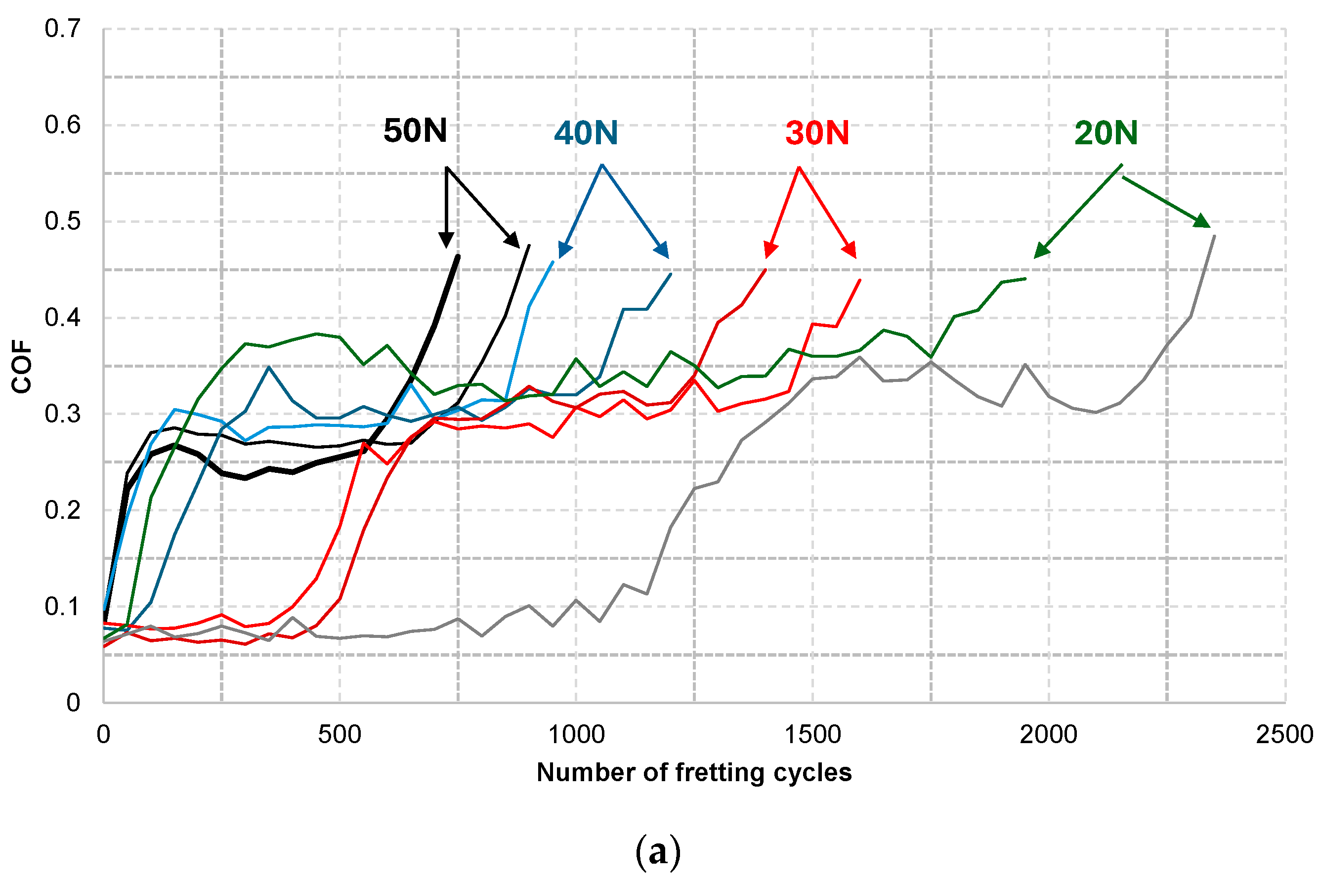
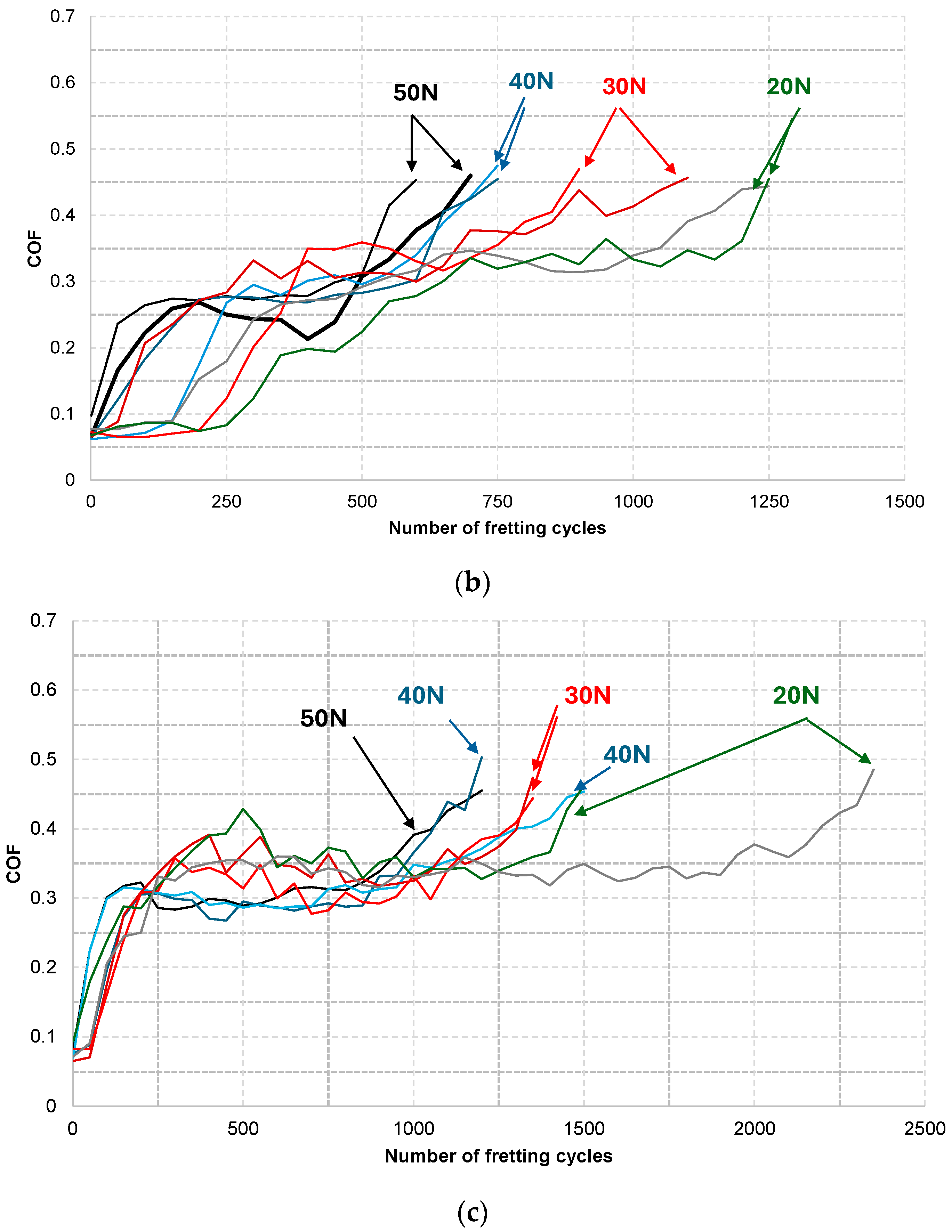
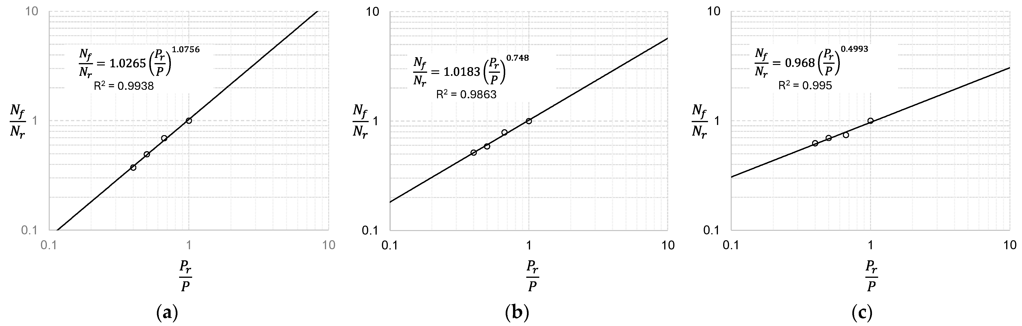
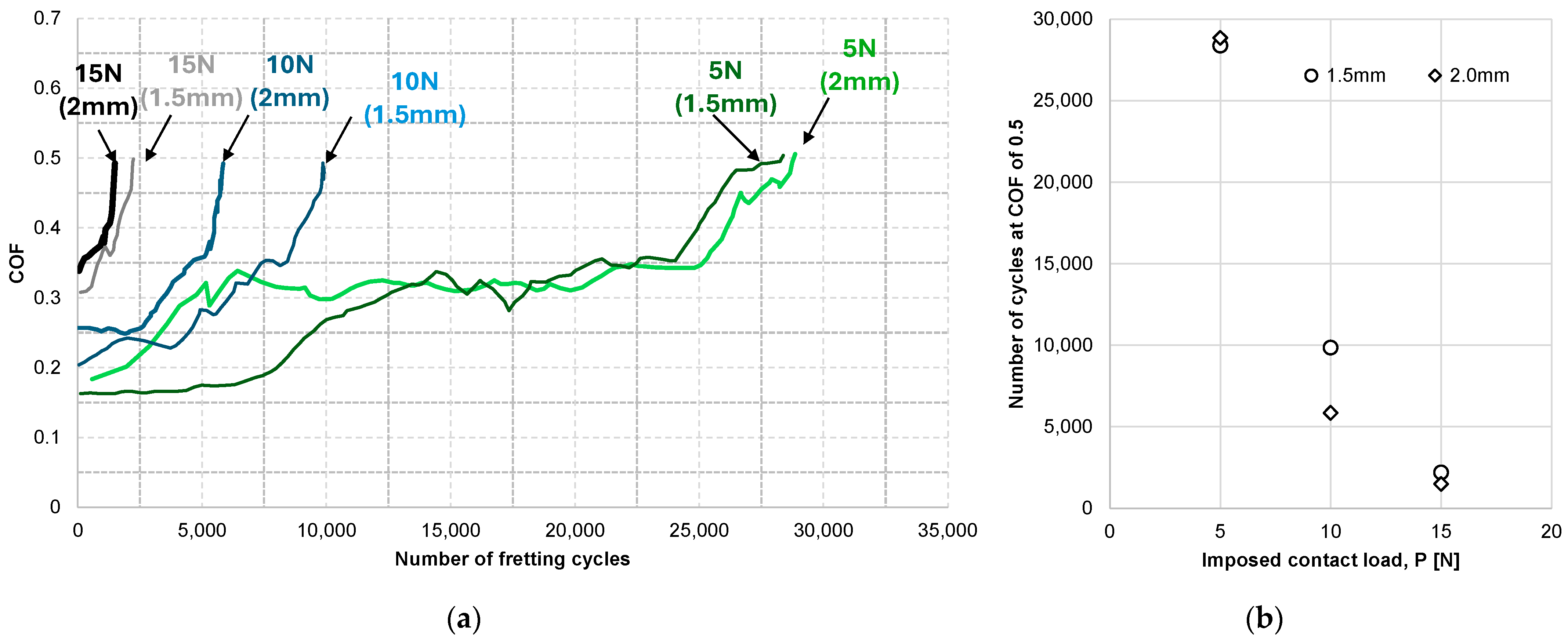
3.1. Effect of Imposed Contact Load

The imposed contact load is one of the most significant factors affecting the fretting wear lifetimes of coatings. Figure 1 shows the COF evolutions of an electro-deposited coating at four different contact loads [13]. As a counterpart of the coating, AISI52100, SUS316L, and ZrO2 balls were selected. Two tests were conducted at each contact load. The initial COF values were lower than 0.15, while the values exceeded 0.45 after a different number of cycles. Differences among evolutions due to imposed contact loads were found. The fretting wear lifetime of the coating was considered to be the fretting cycle when the COF exceeded 0.45. Figure 2 shows the number of cycles at a COF of 0.45 versus imposed contact load scatter. It was apparent that the number of cycles at 0.45 decreased with increased imposed contact load.
In order to analyze the relationship between fretting wear lifetimes and contact load, Equation (5) was used. Because a series of fretting wear tests were conducted under the same test conditions except for the contact load, Equation (5) is simply expressed as
N f N r = P r P n p
l o g N f N r = n p × l o g P r P
For the purpose of curve fitting, Equation (6) was given on the bilogarithmic scale. In Equation (7), np is the load-life exponent. Pr denotes the reference value of the load. That is, if Pr is equal to P, the lifetime, Nf, becomes the reference one (Nr).
There was a deviation between the two fretting wear lifetime values obtained at each load. Thus, the average of the two values was calculated and used for curve fitting. Figure 3 presents the results of curve fitting on the bilogarithmic scale. The reported quality of fit (R2) shows that Equation (7) provided an adequate description of the scatter. That is, the fretting wear lifetime of the coating could be expressed as an inverse power law function of a contact load. The load-life exponents were found to vary with respect to the counterpart material. The value for the AISI 52100 balls was close to unity, while the values for the SUS316L and ZrO2 balls were lower than unity.
Figure 4 shows the COF evolutions of an aromatic thermosetting copolyester-MoS2 coating in a gross slip regime [14]. Fretting wear tests were conducted at three different contact loads: 5 N, 10 N, and 15 N. In this case, the fretting wear lifetime of the coating was defined as the cycle when the COF exceeded 0.5. Figure 4b shows the number of cycles at a COF of 0.5 versus imposed contact load scatter. Figure 5 shows the measured data on the bilogarithmic scale and fitted curves with Equation (7). R-squared shows that a fitted curve adequately described the lifetime-load scatter. The load-life exponents for the coating were greater than those found at the fretted electro-deposited coating. It was identified that the load-life exponents varied with respect to the type of coating and the material of the counterpart.

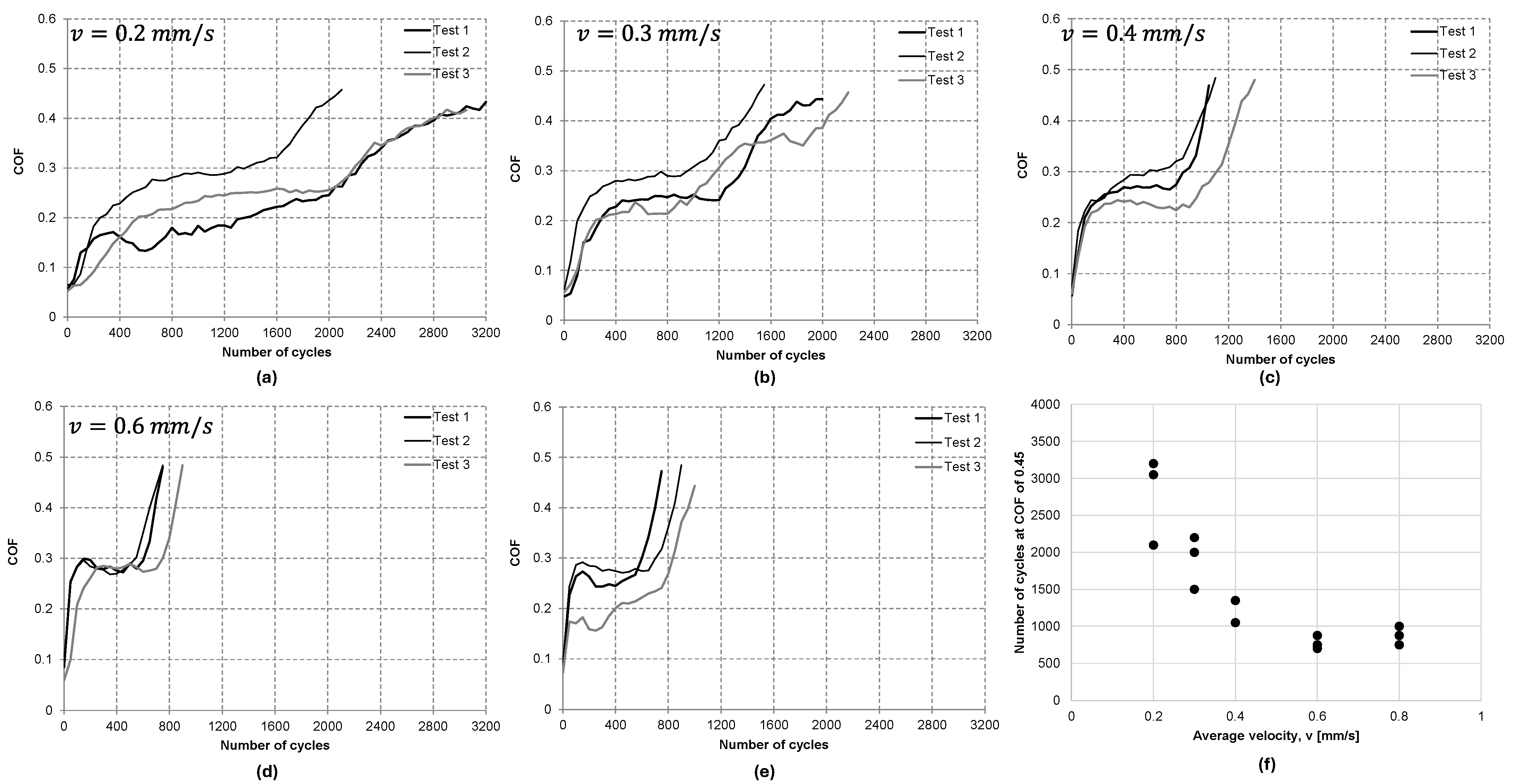
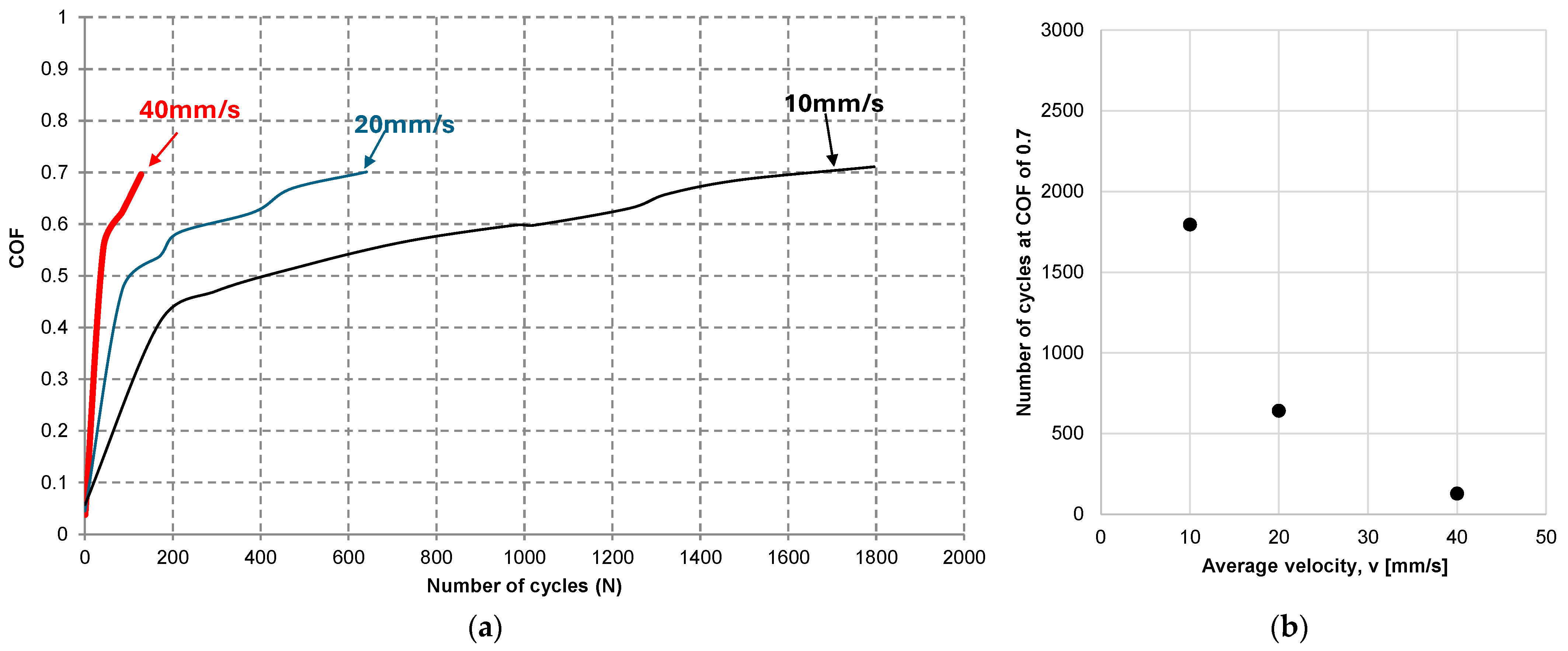
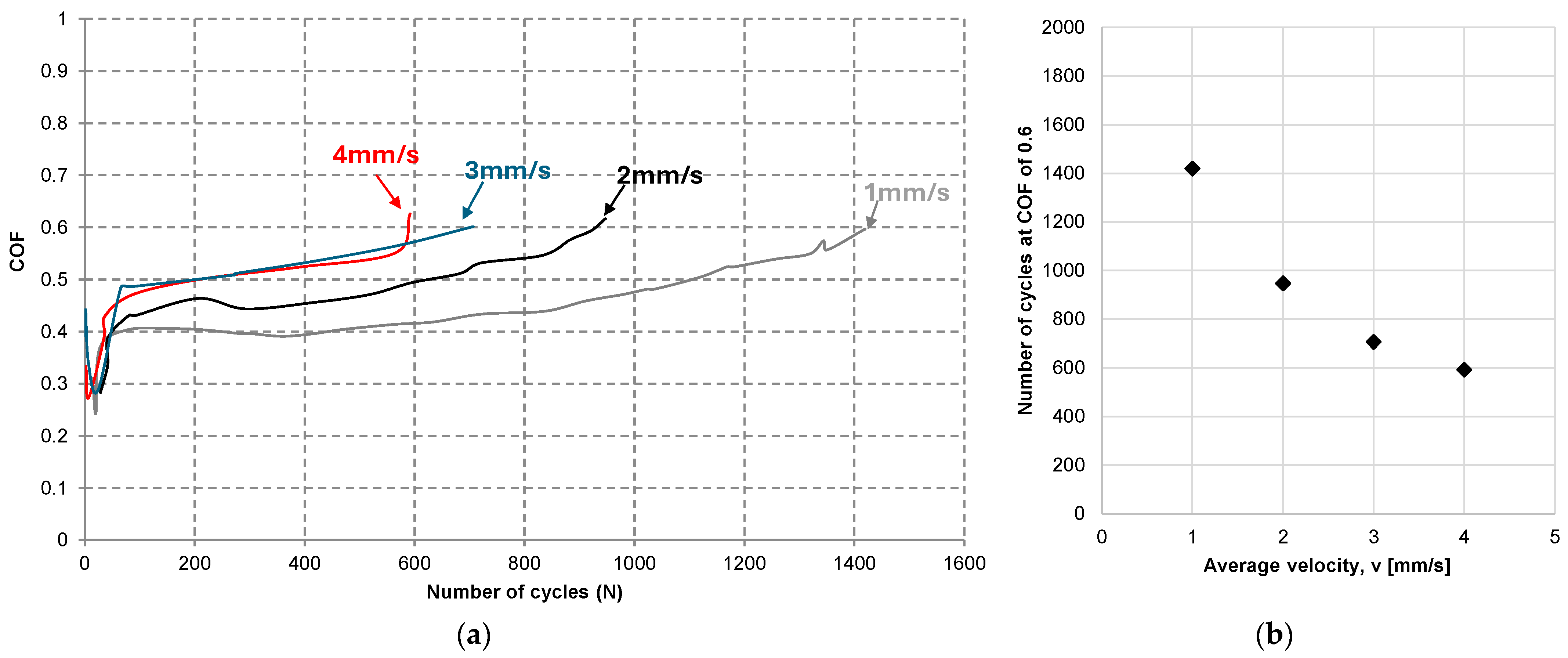
3.2. Effect of Imposed Average Velocity During Gross Slip

The imposed displacement amplitude and frequency are other significant factors affecting the fretting wear lifetimes of coatings. In this study, an imposed average velocity was introduced, combining the imposed displacement amplitude and frequency of motion. Specifically, the imposed average velocity was defined as 4 × displacement amplitude × frequency. Figure 6 shows the COF evolutions of electro-deposited coatings at various average velocities in the gross slip regime. COF values were reproduced up to 0.45 from [15]. The numbers of fretting cycles at a COF of 0.45 are shown in Figure 6f. It was apparent that the number of cycles at a COF of 0.45 decreased with an increased average velocity during gross slip.
The COF evolutions of coatings, measured under various imposed average velocities, were found in other studies [9,16]. Figure 7 shows COF values of a thermal sprayed coating for aerospace gas turbine components. Although the initial COF values ranged from 0.15 to 0.18, the COF growth rate after the steady state was observed to differ according to the imposed average velocity. The fretting wear tests with the coating were terminated when the COF exceeded 0.33, since some parts of the coating layer were removed and the substrate appeared at contact [9]. At the COF, surface images showed that the substrate appeared at the contact surface and the anti-fretting performance of the remaining coating was lost. Thus, the fretting wear lifetime of the thermal sprayed coating at the given condition was defined as the cycle at which the COF reaches 0.33. Figure 8 shows the COF evolutions of an epoxy coating in a gross slip regime [16]. Although the initial COF values were low, the values increased rapidly. The substrate for the coating was GCr15 bearing steel, as well as the counterpart. The COF of self-mating GCr15 steel ranges from 0.7 to 0.9 in dry conditions. Thus, the fretting wear lifetime of this coating was defined as the number of cycles when the COF became 0.7. As the average velocity increased, the fretting wear lifetimes of the coating were significantly reduced, as shown in Figure 8b. Other research shows the COF evolutions obtained at different average velocities, as shown in Figure 9a [17]. An aluminum bronze coating was tested under a gross slip regime (at a contact load of 10 N and an imposed displacement amplitude of 0.05 mm), with the finding that the COF growth rate varied with respect to the imposed average velocity. In this article, the fretting wear lifetime of the coating was defined as the number of cycles when the COF exceeded 0.6, since the coating was worn out and the substrate appeared at contact [17]. Figure 9b presents the relationship between the number of cycles at 0.6 and the imposed average velocity. As for other relationships described above, as the average velocity increased, the number of cycles at 0.6 was observed to decrease.
In order to identify the relation between fretting wear lifetime and the imposed average velocity during gross slip, Equation (5) can be expressed by simply applying the reference value of contact load (i.e., P = Pr).
N f N r = v r v n v
l o g N f N r = n v × l o g v r v
For the purpose of curve fitting, Equation (8) was then given on the bilogarithmic scale, as shown in Figure 9. On the bilogarithmic scale, the slope of the fitted curve corresponds to nv, the average velocity-life exponent. Figure 10 shows the relationship between the fretting wear lifetime of a coating and the imposed average velocity. The R2 values were greater than 0.98, indicating that a fitted curve provided an adequate description of the relation. As shown in Figure 10, the parameter nv differed according to the type of coating; the nv values for the electro-deposited coating (Figure 10a), thermal sprayed coating (Figure 10b), and epoxy coating (Figure 10c) were greater than unity. Particularly, the nv value for the electro-deposited coating against the AISI 52100 counterpart was greater than np, as found in Figure 3a; note that the electro-deposited coating for Figure 10a is the same as that for Figure 1a in terms of coating properties. Meanwhile, nv for the aluminum bronze coating was lower than unity.

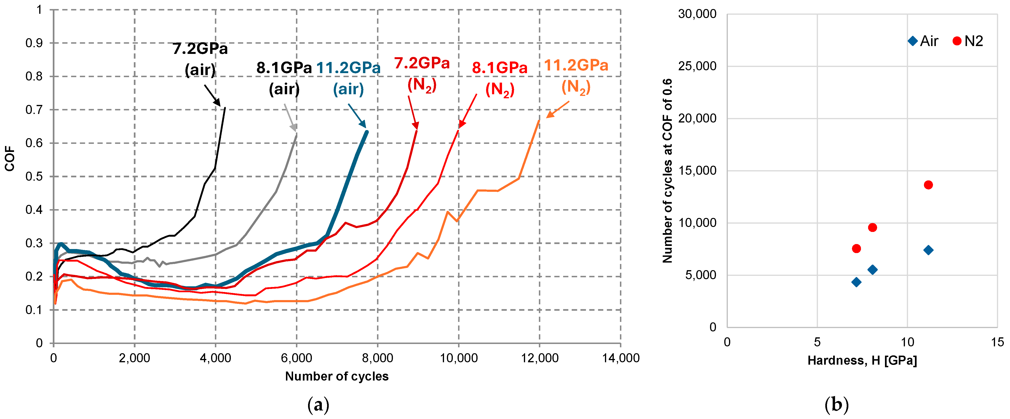
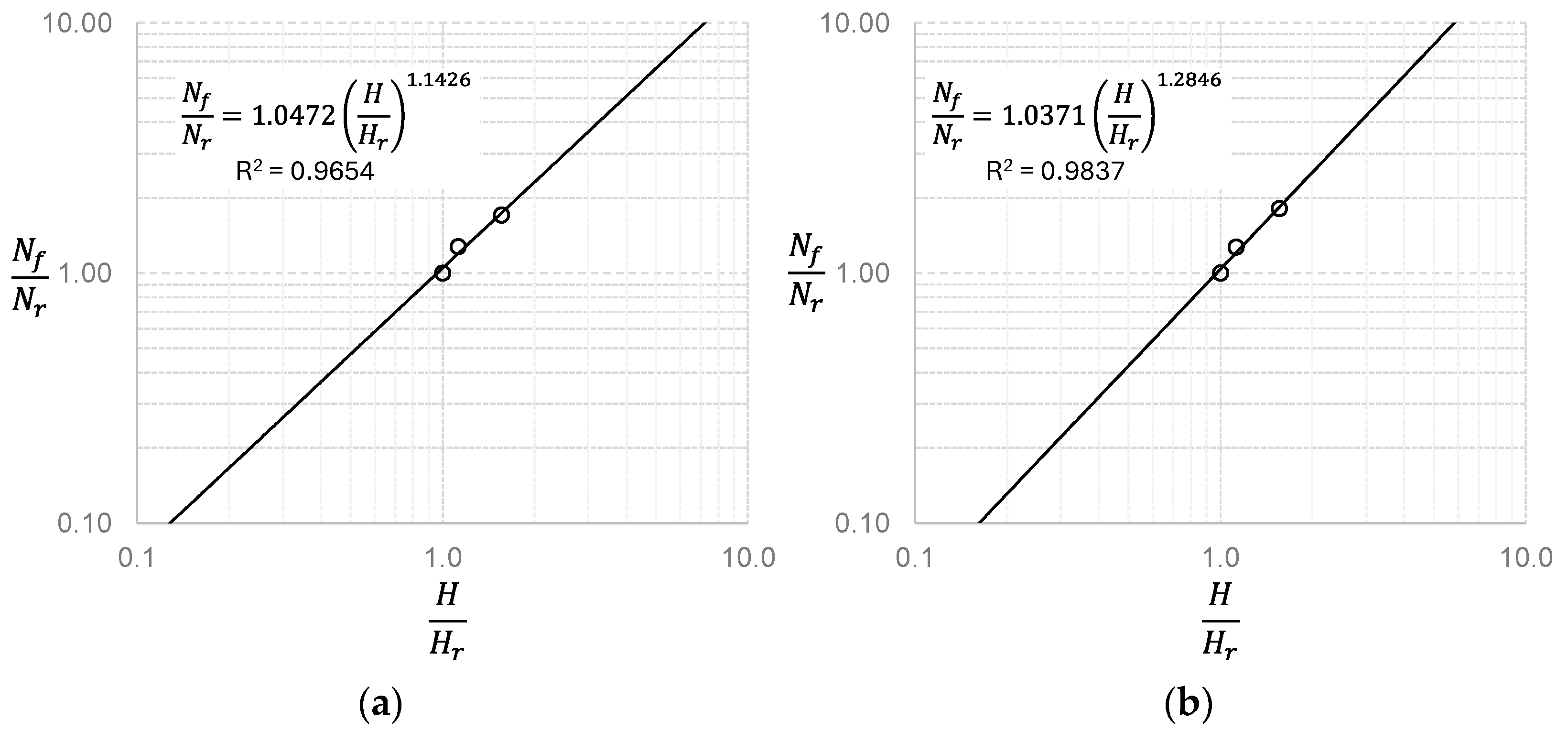
3.3. Effects of Coating Hardness and of Initial Surface Roughness

Other factors such as the hardness of coatings or the initial surface roughness of counterparts can affect fretting wear lifetimes. In order to identify how the hardness of a coating affects fretting wear lifetimes in terms of the number of fretting cycles, the COF evolutions of graphite-like carbon coatings were collected from the literature [19]. Fretting wear tests with the coating were conducted at a contact load of 40 N, at a displacement amplitude of 0.1 mm, and at a frequency of 5 Hz, using a ball-on-flat contact apparatus. The graphite-like carbon coating was produced by changing the negative bias voltage in a magnetron sputtering system. Fretting wear tests were carried out in dry air and N2 conditions, and the COF evolutions were measured as shown in Figure 11. The initial COF values were lower than 0.2. After the initial running-in period, the values were almost steady (steady state). Finally, the COF value increased rapidly. In this article, the fretting wear lifetime of the coating was determined when the COF value exceeded 0.6. Figure 11b shows the number of cycles at 0.6 with respect to the hardness of the graphite-like carbon coating. The fretting wear lifetime of the coating tended to increase with increased coating hardness. In order to identify the relationship between the hardness of the coating and the fretting wear lifetime, one can simplify Equation (5) as Equation (10).
N f N r = H H r n h
where Hr is the reference hardness and nh denotes the hardness-life exponent.
Figure 12 shows a scatter plot of the fretting wear lifetimes versus hardness of the coating. The reported quality of fit shows that Equation (10) allows fitting the scatter data adequately. The hardness-life exponent, nh, was found to be greater than unity. It was clear that the influence of a test condition (i.e., air or N2) can be quantified with the exponent. Note that the data in Figure 12a were obtained in dry air conditions, while those in Figure 12b were in N2 conditions.
Figure 13a shows the fretting wear lifetimes of a rubber coating against counterparts maintaining different surface roughness values [18]. As the counterpart of the rubber (fluoropolymer) coating, stainless steel balls were used for fretting wear testing. The initial surface roughness of the stainless steel balls was controlled, ranging from 0.02 µm to 0.4 µm regarding the arithmetic average surface roughness (Ra). Fretting wear tests were conducted at a contact load of 10 N and at an average velocity of 0.6 mm. It was reported that the rubber coating was worn out at a COF of 0.33 [18]. Thus, in this study, the fretting wear lifetime of the coating was defined as the fretting cycle at a COF of 0.33. It was observed that the fretting wear lifetime of the coating (Nf) decreased with increased average surface roughness (Ra) of the counterpart. Figure 13b shows the relationship between Nf and Ra of the counterpart on the bilogarithmic scale. It was possible to fit the scatter with a power law, such as Equation (11).
N f N r = R a r R a n a
where na denotes the roughness-life exponent. Rar presents the reference value of the arithmetic average surface roughness.

4. Discussion

In this article, a fretting wear lifetime model of a low-friction coating was introduced, including significant factors that influence fretting lifetimes. Among many factors, the contact load, imposed average velocity, coating hardness, and surface roughness of a counterpart were considered. As a result of the analysis, the following equation was obtained.
N f = N r P r P n p v r v n v H H r n h R a r R a n a
Based on the fitted data of the electro-deposited coatings [13,16], Equation (12) can be expressed as
N f = N r P r P 1.0756 v r v 0.9321
Here, the initial surface roughness of the counterpart maintained as constant, as did the coating hardness. This equation selected the two exponents, np and nv, of fitted curves for determining the effects of the imposed contact load and of the imposed average velocity, respectively. The reference values (Nr, pr, and vr) were determined as the test condition with the longest fretting wear lifetime among the measured data.
Table 1 shows a comparison between the measured and predicted fretting wear lifetime values of an electro-deposited coating against an AISI52100 counterpart. Table 2 and Table 3 present direct comparisons between the measured and predicted lifetime values for graphite-like carbon coatings and rubber coatings, respectively. The predicted fretting wear lifetime of the coating was determined with Equation (13). Number 1 on the table was used for the reference values (i.e., Nr, Pr, and vr). The error was calculated as the ratio of the difference between the measured and predicted values to the predicted one. The biggest error was found on the fretting wear lifetimes of the coating obtained at a contact load of 50 N and an average velocity of 0.6 mm/s. This error arose from the difference between the fitted values and measured ones at the two test conditions, though it was identified from Figure 10a that the R-squared of the curve fitting was greater than 0.95. Fretting wear tests often bring about the deviation of fretting wear lifetime values even under constant test conditions. For example, under the test condition (at a contact load of 50 N and an average velocity of 0.2 mm/s), the maximum difference among the measured lifetime values was about 1100 cycles, corresponding to 34 percent. It was reported that such a difference between evolutions might be attributed to the variance in the initial coating thickness [13]. For minimizing the biggest error of the test condition, the addition of an error term to Equation (13) might be considered. Thus, future work needs to be focused on reducing errors.
In order to investigate the influence of other factors on fretting wear lifetime, additional experimental data need to be obtained. Particularly, environmental conditions such as atmosphere [12,24], relative humidity [25], and temperature [26] could affect the fretting wear lifetime of a coating. Beyond the environmental conditions, contact geometry might also influence the fretting wear lifetime of coatings [27]. Thus, environmental conditions and contact geometry should be included as parameters of a fretting wear lifetime model. As the number of factors included in the model increases, the error between the experimental and calculated values might increase. Thus, it is necessary to minimize such errors.

5. Conclusions

In this article, a fretting wear lifetime model for a coated system was developed. Experimental COF evolutions of various low-friction coatings obtained from the literature were used for building the model. The fretting wear lifetime of a coating was defined as the number of cycles when the COF exceeded a critical value. The fretting wear lifetimes of a coating are affected by various factors. In this study, the relationship between the lifetime and the factor was identified with the model. The selected factors were an imposed contact load, an imposed average velocity (the combination of displacement amplitude and frequency of fretting motion), the hardness of a coating, and the initial surface roughness of an uncoated counterpart against a coating. The following conclusions were drawn:
  • The fretting wear lifetimes of coatings were found to decrease with increased contact load. It was noted that the relationship between the imposed contact load and fretting wear lifetimes can be described by the inverse power law. The load-life exponent was observed to vary according to the type of coating. In addition, the type of counterpart for the electro-deposited coating affected the exponent.
  • The fretting wear lifetimes of coatings were found to decrease with increased average velocity during gross slip. It was identified that it was possible to describe the relationship between an imposed average velocity and fretting wear lifetimes of a coating with an inverse power law. The velocity-life exponents were found to vary according to the type of coating.
  • A fretting wear lifetime model for an electro-deposited coating was given with consideration of two factors: the contact load and average velocity. A direct comparison between the experimental and predicted lifetime values was employed, and a maximum error of 27 percent was found. Considering the variance among the experimental data for the coating (34 percent), one might accept the maximum error of the fretting wear lifetime model.
  • Meanwhile, the relationship between the initial surface roughness of a counterpart and the fretting wear lifetime was identified; the fretting wear lifetime of a coating decreased with increased initial surface roughness. The influence of coating hardness on the fretting wear lifetime was identified. It was observed that the relationship between coating hardness and the fretting wear lifetime was described with a power law.
The proposed fretting wear lifetime model enables the incorporation of various experimental factors as variables. Thus, other factors such as test temperature, atmosphere, and relative humidity need to be included in the model. This remains as work to be accomplished by future research. As the number of factors included in the model increases, the error between the experimental and calculated values might increase. Thus, it is necessary to minimize such errors.
This proposed fretting wear lifetime model could aid in the selection of an adequate coating from a given coating database. Thus, further work should include the construction of a database containing the fretting wear lifetimes of low-friction coatings, test conditions, and material properties.

Funding

This research was conducted with the support of the Korea Institute for Advancement of Technology funded by the government (Ministry of Trade, Industry and Energy) in 2023 (Project No. P0023691, Specialized Workforce Development Program for Space Materials, Parts, and Equipment). This work was supported by a 2024 Korea Aerospace University faculty research grant.

Data Availability Statement

The data used to support the findings of this study are available from the corresponding author upon request.

Conflicts of Interest

The author declares no conflicts of interest.

References

  1. Waterhouse, R.B. Fretting wear. Wear 1984, 100, 107–118. [Google Scholar] [CrossRef]
  2. Vingsbo, O.; Soderberg, S. On Fretting Maps. Wear 1988, 126, 131–147. [Google Scholar] [CrossRef]
  3. Hills, D.A.; Nowell, D. Mechanics of Fretting Fatigue, 1st ed.; Springer: Berlin/Heidelberg, Germany, 1994. [Google Scholar]
  4. Geringer, J.; Macdonald, D. Friction/fretting-corrosion mechanisms: Current trends and outlooks for implants. Mater. Lett. 2014, 134, 152–157. [Google Scholar] [CrossRef]
  5. Kim, H.K.; Lee, Y.H.; Heo, S.P. Mechanical and experimental investigation on nuclear fuel fretting. Tribol. Int. 2016, 39, 1305–1319. [Google Scholar] [CrossRef]
  6. Antler, M. Survey of contact fretting in electrical connectors. IEEE Trans. Compon. Packag. Technol. 1985, 8, 87–104. [Google Scholar] [CrossRef]
  7. van Dijk, P.; Rudolphi, A.K.; Klake, D. Investigations on Electrical Contacts Subjected to Fretting Motion. In Proceedings of the 21st International Conference on Electrical Contacts (ICEC), Zurich, Switzerland, 9–12 September 2002. [Google Scholar]
  8. Koiprasert, H.; Dumrongrattana, S.; Niranatlumpong, P. Thermally sprayed coatings for protection of fretting wear in land-based gas-turbine engine. Wear 2004, 257, 1–7. [Google Scholar] [CrossRef]
  9. Kim, K.; Korsunsky, A.M. Effects of imposed displacement and initial coating thickness on fretting behaviour of a thermally sprayed coating. Wear 2011, 271, 1080–1085. [Google Scholar] [CrossRef]
  10. Langlade, C.; Vannes, B.; Taillandier, M.; Pierantoni, M. Fretting behavior of low-friction coatings: Contribution to industrial selection. Tribol. Int. 2001, 34, 49–56. [Google Scholar] [CrossRef]
  11. Kim, K. Statistical determination of a fretting-induced failure of an electro-deposited coating. Coatings 2017, 7, 48. [Google Scholar] [CrossRef]
  12. Bill, R.C. Review of factors that influence fretting wear. A.S.L.E. Trans. 1982, 21, 239. [Google Scholar]
  13. Jun, T.S.; Kim, K. Influence of load on the friction coefficient of fretted electro-deposited coatings against steel and zirconia balls. Int. J. Surf. Sci. Eng. 2016, 10, 514–526. [Google Scholar] [CrossRef]
  14. Zhang, Z.; Wood, R.J.K.; Lu, P.; Guo, Y.; Wang, D. Effect of pv values on dry fretting and wear characteristics of aromatic thermosetting co-polyester (ATSP)-MoS2 coatings. Tribol. Int. 2023, 188, 108889. [Google Scholar] [CrossRef]
  15. Hur, J.W.; Baek, S.Y.; Kim, K. Effect of displacement on kinetic frictional behaviour between electro-deposited coating and AISI 52100 steel under fretting conditions. Proc. IME J. J. Eng. Tribol. 2016, 230, 1172–1179. [Google Scholar] [CrossRef]
  16. Li, Y.; Ying, S.; Zhao, Y.; Li, Z.; Cao, J.; Wu, X.; Du, P.; Wu, T.; Yu, C.; Xie, G. Study on fretting friction properties based on GCr15 alloy and liquid epoxy resin protective coatings on GCr15 alloy. Colloids Surf. A Physicochem. Eng. Asp. 2024, 696, 134364. [Google Scholar] [CrossRef]
  17. Shi, Z.; Xu, L.; Deng, C.; Liu, M.; Liao, H.; Darut, G.; Panche, M. Effects of frequency on the fretting wear behavior of aluminum bronze coatings. Surf. Coat. Tech. 2023, 457, 129306. [Google Scholar] [CrossRef]
  18. Baek, D.L.; Khonsari, M.M. Fretting behavior of a rubber coating: Effect of temperature and surface roughness variations. Wear 2008, 265, 620–625. [Google Scholar] [CrossRef]
  19. Shi, X.; Liskiewicz, T.W.; Beake, B.D.; Sun, Z.; Chen, J. Fretting wear behavior of graphite-like carbon films with bias-graded deposition. App. Surf. Sci. 2019, 494, 929–940. [Google Scholar] [CrossRef]
  20. Lundberg, G.; Palmgren, A. Dynamic Capacity of Roller Bearings. Acta Polytech. Mech. Eng. Series 1952, 2, 96–127. [Google Scholar]
  21. Bhushan, B. Introduction to Tribology, 1st ed.; John Wiley & Sons, Inc.: New York, NY, USA, 2002. [Google Scholar]
  22. Zaretsky, E.V.; Poplawski, J.V.; Miller, C.R. Rolling Bearing Life Prediction—Past, Present, and Future; NASA/TM-2000-210529; National Aeronautics and Space Administration: Washington, DC, USA, 2000.
  23. ISO 98:1990(E); Rolling Bearing-Dynamic Load Ratios and Rating Life. International Organization for Standardization: Geneva, Switzerland, 1990.
  24. Endo, K.; Goto, H. Effects of environment on fretting fatigue. Wear 1978, 48, 347–367. [Google Scholar] [CrossRef]
  25. Rybiak, R.; Fouvry, S.; Liskiewicz, T.; Wendler, B. Fretting wear of a TiN PVD coating under variable relative humidity conditions-development of a ‘composite’ wear law. Surf. Coat. Tech. 2008, 202, 1753–1763. [Google Scholar] [CrossRef]
  26. Rybiak, R.; Fouvry, S.; Bonnet, B. Fretting wear of stainless steels under variable temperature conditions: Introduction of a ‘composite’ wear law. Wear 2010, 268, 413–423. [Google Scholar] [CrossRef]
  27. Willert, E. Influence of Profile Geometry on Frictional Energy Dissipation in a Dry, Compliant Steel-on-Steel Fretting Contact: Macroscopic Modeling and Experiment. Machines 2023, 11, 484. [Google Scholar] [CrossRef]
Figure 1. COF evolutions of electro-deposited coatings against different counterparts under a gross slip regime (displacement amplitude of 0.2 mm and frequency of 1 Hz), redrawn from [13]: (a) AISI52100 ball; (b) SUS316L ball; (c) ZrO2 ball.
Machines 12 00910 g001aMachines 12 00910 g001b
Figure 2. Number of fretting cycles at COF of 0.45 versus contact load scatters: (a) AISI52100 ball; (b) SUS316L ball; (c) ZrO2 ball.
Machines 12 00910 g002
Figure 3. Relationship between fretting wear lifetime (Nf) and imposed contact load (P) on the bilogarithmic scale: (a) AISI52100 ball; (b) SUS316L ball; (c) ZrO2 ball. Nr and Pr denote the reference lifetime and the reference load, respectively.
Machines 12 00910 g003
Figure 4. COF evolutions of an aromatic thermosetting copolyester-MoS2 coating under a gross slip regime (a frequency of 10 Hz), redrawn from [14]. (a) COF evolutions at different imposed contact loads. Note that the value in parenthesis denotes the displacement amplitude. (b) Number of fretting cycles at a COF of 0.5 versus the contact load.
Machines 12 00910 g004
Figure 5. Relationship between fretting wear lifetime (Nr) and imposed contact load (P) on the bilogarithmic scale: (a) a displacement amplitude of 1.5 mm; (b) a displacement amplitude of 2 mm. Nr and Pr denote the reference lifetime and the reference load, respectively.
Machines 12 00910 g005
Figure 6. COF evolutions of electro-deposited coatings at various average velocities (a contact load of 50 N), redrawn from [15]: (a) 0.2 mm/s; (b) 0.3 mm/s; (c) 0.4 mm/s; (d) 0.6 mm/s; (e) 0.8 mm/s; (f) number of fretting cycles at a COF of 0.45 versus the imposed average velocity. Note that the imposed average velocity was defined as 4 × displacement amplitude × frequency.
Machines 12 00910 g006
Figure 7. COF evolutions of a thermal sprayed coating under a gross slip regime (a contact load of 10.3 kN and a frequency of 2.5 Hz), redrawn from [9]: (a) COF evolutions at three different average velocities; (b) number of fretting cycles at a COF of 0.33 versus the imposed average velocity; v is equal to 4 × displacement amplitude × frequency.
Machines 12 00910 g007
Figure 8. COF evolutions of an epoxy coating in a gross slip regime (a contact load of 20 N), redrawn from [16]: (a) COF evolutions at three average velocities; (b) number of fretting cycles at a COF of 0.7 versus the imposed average velocity; v is equal to 4 × displacement amplitude × frequency.
Machines 12 00910 g008
Figure 9. COF evolutions of an aluminum bronze coating under a gross slip regime (a contact load of 10 N), redrawn from [17]: (a) COF evolutions; (b) number of fretting cycles at a COF of 0.6 versus the imposed average velocity; v is equal to 4 × displacement amplitude × frequency.
Machines 12 00910 g009
Figure 10. Relationship between fretting wear lifetimes and imposed average velocity on the bilogarithmic scale: (a) electro-deposited coating; (b) thermally sprayed coating; (c) epoxy coating; (d) aluminum bronze coating. Nr and vr denote the reference lifetime and the reference average velocity, respectively.
Machines 12 00910 g010
Figure 11. COF evolutions of graphite-like carbon coatings at various hardness values, redrawn from [19]: (a) COF evolutions in dry air and N2 conditions; (b) number of fretting cycles at a COF of 0.6 versus coating hardness.
Machines 12 00910 g011
Figure 12. Relationship between fretting wear lifetimes (Nf) and coating hardness (H) on the bilogarithmic scale: (a) in air condition; (b) in N2 condition. Nr and Hr denote the reference lifetime and the reference hardness, respectively.
Machines 12 00910 g012
Figure 13. Fretting wear lifetime of a rubber coating with respect to the arithmetic average surface roughness (Ra), redrawn from [18]: (a) number of fretting cycles at COF of 0.3; (b) relationship between fretting wear lifetimes and average roughness on the bilogarithmic scale. Nr and Rar denote the reference lifetime and the reference surface roughness, respectively.
Machines 12 00910 g013
Table 1. A direct comparison between the measured and predicted fretting wear lifetime of an electro-deposited coating [13,15]. Note that the number 1 is used for the reference value. Error is defined as N f N f / N f .
Test
No
Contact Load, NAverage Velocity, mm/sMeasured
Lifetime ( N f )
Predicted
Lifetime (Nf)
Error
(%)
1200.8217721770%
2300.8150714087%
3400.8107310334%
4500.88128130%
5500.2278329586%
6500.3190020276%
7500.41150155026%
8500.6775106227%
9500.88758138%
Table 2. A direct comparison between the measured and predicted fretting wear lifetime of a graphite-like carbon coating [19]. Note that the numbers 1 and 4 are used for the reference values for each condition. Error is defined as N f N f / N f .
Test
No
Hardness, GPaConditionMeasured
Lifetime ( N f )
Predicted
Lifetime (Nf)
Error
(%)
17.17Air432943290%
28.07Air5523495212%
311.17Air739371783%
47.17H2754675460%
58.07H2956887799%
611.17H213,64013,3272%
Table 3. A direct comparison between the measured and predicted fretting wear lifetime of a rubber coating [18]. Note that the number 1 is used for the reference value. Error is defined as N f N f / N f .
Test
No
Arithmetic Average Surface Roughness (Ra), µmMeasured
Lifetime ( N f )
Predicted
Lifetime (Nf)
Error
(%)
10.02271527150%
20.051278115710%
30.151360716%
40.23483199%
Disclaimer/Publisher’s Note: The statements, opinions and data contained in all publications are solely those of the individual author(s) and contributor(s) and not of MDPI and/or the editor(s). MDPI and/or the editor(s) disclaim responsibility for any injury to people or property resulting from any ideas, methods, instructions or products referred to in the content.

