1. Introduction
Chatter is a significant issue in machining that impacts both the part quality and production efficiency [
1,
2]. To mitigate chatter during manufacturing, stability lobe diagrams (SLDs) are utilized to assess milling stability, aiming at identifying the boundaries between stable and unstable cutting depths in relation to spindle speed [
3]. Although SLDs are valuable for stability analysis, their practical adoption in industry is limited by the high demands for precise measurements and sophisticated modeling to accurately implement the approach. Therefore, further research to enhance the chatter stability analysis must be carried out to address this issue.
Tool–workpiece interaction is essential in selecting an appropriate cutting strategy, as it directly affects the quality, shape, and dimensional accuracy of the machined surface. Varga et al. [
4] developed a method for assessing the effective diameter of a copying cutter during the machining of complex surfaces. Their findings emphasized the significant impact of variations in the tool’s effective diameter, along with the area and volume, on the accuracy of the resulting shapes. Then, Varga et al. [
5] investigated the influence of tool inclination by evaluating surface roughness and topography, and identified the best and unfavorable results of tool inclination for surface quality, giving constructive suggestions for planning the cutting process. Except for these tool–workpiece interactions, chatter is another critical factor that has to be considered when selecting an appropriate cutting strategy. To address this issue, the milling stability modeling has been widely studied in both analytical [
6,
7] and numerical forms [
8]. Karandikar et al. [
9] designed a Bayesian learning approach for identifying stability boundaries and optimal milling parameters. Their results showed that the method operates efficiently and robustly with a limited number of tests/data points. Song et al. [
10] developed a method for predicting milling stability with higher efficiency and accuracy. Their results indicate that accounting for vibration velocity enhances both the efficiency and accuracy over traditional approaches. The primary factors affecting stability are the tooltip dynamics, characterized by frequency response functions (FRF), and the cutting force coefficients. While progress of chatter stability analysis has been achieved, accurately identifying the tooltip FRF remains a challenge that limits the effectiveness of chatter stability prediction.
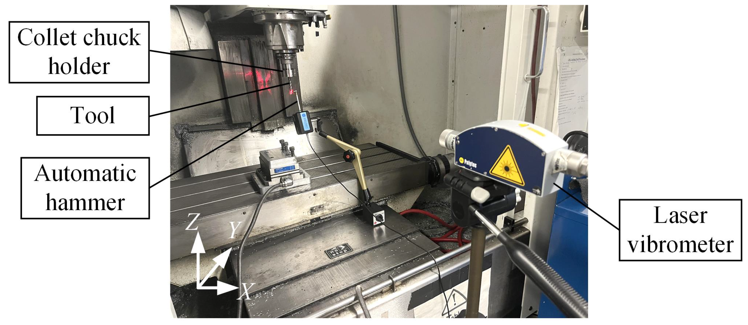
The tooltip FRF is typically obtained through impact hammer testing, which employs Experimental Modal Analysis (EMA) to calculate the FRF of the tool point by measuring the impact force and the structural response [
1]. However, it is common to use various tools and holders on a machine, requiring the tool point FRF to be measured for each tool–holder combination. This process must be repeated for every setup, which is time-consuming, increases machine downtime, and raises production costs. An alternative approach is the model-based approach [
11,
12], but modeling the entire machine tool structure, including the tool and holder, is challenging. This is mainly due to the lack of certain critical information, such as bearing locations, and the difficulty in determining the contact characteristics of the numerous joints within the machine tool structure.
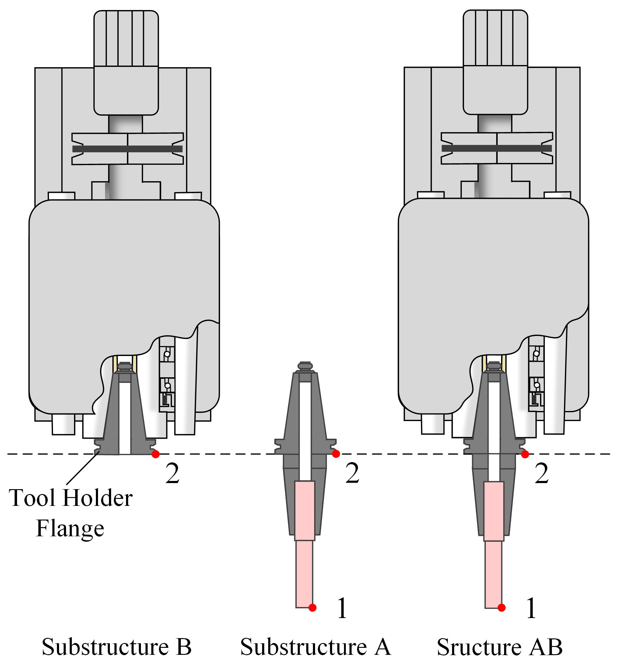
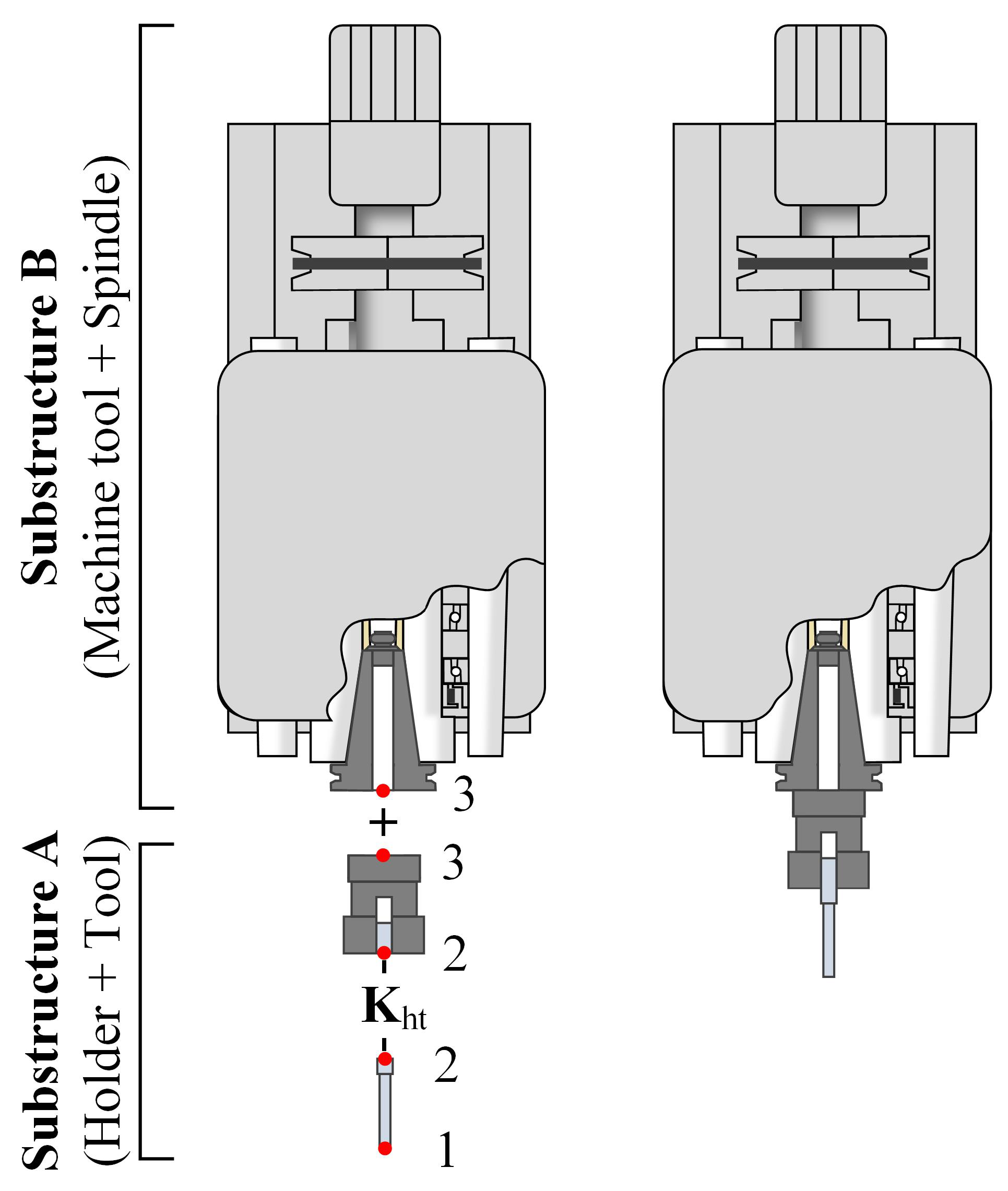
Receptance coupling (RC) or receptance coupling substructure analysis (RCSA) is an effective mathematical technique for predicting assembly dynamics, combining experimental dynamic measurements of the machine tool substructure with the analytically derived dynamics of the tool–holder assembly. Schmitz and Donalson [
13] first introduced RCSA to the field of machining and, since then, it has gained widespread adoption among researchers for various applications in machine tool dynamics [
14,
15,
16]. A major difficulty in implementing the RCSA method arises from the complexities of the joint interfaces between the spindle, holder, and tool. A widely adopted approach, proposed by Schmitz et al. [
13,
17], represents the tool–holder contact as a lumped spring–damper system, specifically at the location where the tool extends from the holder. The tool–holder interface is characterized by stiffness and damping coefficients, which are determined by manually matching the calculated tooltip FRF with the experimental measurements. They found that the dynamic response of the tooltip can be predicted by an appropriate contact model. Park et al. [
18] presented an improved method for identifying the parameters of the lumped contact model for the tool–holder joint, considering both translational and rotational degrees of freedom. They verified that the rotational degree of freedom at the spindle played a significant role in tool point dynamics. Ertürk et al. [
19] were the first to model the spindle–holder–tool system by combining Timoshenko beam theory with the lumped contact model. Their analysis revealed that the rotational contact parameters at both interfaces are less critical than the translational ones. Since then, many researchers [
20,
21,
22] have made significant efforts to improve the identification of the lumped contact model for the tool–holder interface. More recently, Matthias et al. [
23] found that while the first mode of a system can be well-fitted using different parameter sets from various identification methods, these parameters are not transferable to other tool clamping lengths or combinations with other tools, indicating they do not represent the true interface parameters. They suggested a new method for determining the real contact dynamics, which involves measuring the dynamics of the holder–tool assembly at free–free end conditions and identifying the contact parameters through a fitting algorithm. Yu et al. [
24] investigated joint stiffness in the tool holder system using a practical approach that unified the system and its supports as constraints, reducing complexity. Their findings demonstrated the method’s effectiveness in simplifying modeling while ensuring engineering accuracy.
In contrast to the single lumped contact model between the tool and holder, a more realistic but more intricate approach incorporates a multi-point elastic coupling between the components, often referred to as the distributed joint interface. Namazi et al. [
25] modeled the connection between the tapered surface of spindle and tool holder by uniformly distributed springs in orthogonal directions, whose parameters are identified using a least-squares curve-fitting algorithm. The method was experimentally validated and shown to facilitate wear analysis by removing discrete contact springs. Schmitz et al. [
26] proposed a multi-point receptance coupling substructure analysis (RCSA) technique, involving coupling the portion of the tool within the holder to the clamping section of the holder at several equally spaced points along the insertion length. This study concluded that a second-order relationship effectively describes the dependence of stiffness on tool blank diameter. Kiran [
27] modeled the holder–tool contact as a flexible component, and the results showed that the proposed identification procedure achieved excellent agreement between predictions and measurements, confirming the model’s efficiency. Recently, Akbari et al. [
28] proposed techniques to obtain the real connection parameters with higher efficiency, combining simple sound measurement of tool–holder assembly under free–free end conditions with the distributed joint interface, and also presented an identification method for the model parameters. Despite their improved accuracy in predicting assembled dynamics, disturbed contact models are more complex and computationally intensive, leading to time-consuming calculations.
As seen in the above studies, although the lumped contact model simplifies the modeling and calculation effort significantly, the identified contact parameter values are valid only for that particular assembly of tool–holder, and are not transferable to other tool clamping lengths or to combinations with other tools. While some research has focused on identifying the true contact parameters, these methods often require specialized experimental setups, which are not commonly available in industrial environments.
This paper proposes a novel method to identify the contact parameters between the holder and tool based on the RCSA approach and conventional impact hammer testing. Two descriptions of the proposed method are provided, one for different tools and the other for varying clamping lengths. The novelties of this paper can be summarized in the following three points:
The proposed method can identify transferable contact dynamics, enabling the extrapolation of the results to other tool lengths or tool clamping lengths. This is achieved through conventional impact hammer testing at the tooltip on a machine tool, eliminating the need for repeated hammer tests and specialized testing setups.
Improved initial assumptions of the contact parameters are given based on physical laws and existing experimental observations. This facilitates the identification of the true contact dynamics, rather than a solution confined to a specific tool configuration.
Two descriptions of the proposed method are developed based on the improved initial assumptions and receptance coupling, making it applicable to different tool lengths or tool clamping lengths, thus broadening the method’s range of application.
It has been demonstrated that these assumptions are reasonable, and enhance the accuracy of contact parameter identification. Further, based on the new method, the identified results can be transferred to other clamping lengths or combinations with other tools, which significantly improve the prediction accuracy in both tooltip dynamics and milling stability. Therefore, this study provides an industrial-friendly method for obtaining the tool–holder interface parameters, eliminating the need for repeated hammer tests and specialized testing setups.
4. Discussion
In the Results section, the tool–holder contact parameters are identified by different techniques. Then, these contact parameters are first used to predict the tool point dynamics under the clamping conditions from which those parameters are obtained. In essence, all identification techniques are curve-fitting approaches, so that the tool point FRF used for identification can be accurately predicted using the identified contact parameters.
As noted in [
23], the real contact parameters should be able to predict tool point FRF when only the overhang length or total length of the tool is changed. Additionally, for a specific tool, the contact dynamics can also be approximately applied to various clamping lengths [
31]. In other words, the influence of various clamping lengths on tool–holder contact dynamics is limited, which was experimentally validated by Matthias et al. [
23]. Based on these conclusions, when the parameters obtained from different techniques are used to approximately predict the tool point FRFs under various clamping lengths, the results are expected to be close to the measured FRFs for each clamping length. However, only the proposed approach achieves predictions with acceptable accuracy. This conclusion is further validated by the predicted stability boundaries of chatter.
The reason for this outcome, as explained in [
23], is that although the tool point FRFs can be accurately fitted, the identified contact parameters at the tool–holder interface may be unreliable due to the presence of multiple parameter sets that can achieve equally good fits to the FRFs. Matthias et al. [
23] and Akbari et al. [
28] proposed identification techniques that can identify the real contact parameters at the tool–holder connection. Both of the methods are based on the measurements under the free–free end condition with additional experimental devices, which are usually not available in the industrial environment. This paper proposes an approach that relies on measurements of only standard impact hammer testing under two clamping or overhang lengths. Assumptions that restrict the contact parameters for different clamping lengths are given based on the known physical findings. The results of both predicted tool point FRF using the identified parameters from this new approach and the stability boundaries with this FRF verify the efficiency of the proposed method. Therefore, the assumptions established in this study are proved to be reasonable.
The proposed approach can efficiently provide the approximate tool point FRF under different clamping lengths or overhang lengths with acceptable accuracy. It should be emphasized that it is an approximated identification method, so uncertainties are present in the identified results. One potential source of uncertainty lies in the identification errors of the spindle dynamics. Additionally, as a consequence of the flaw of the RCSA technique, the proposed method could have lower identification accuracy if close modes exist in the end point dynamics.


