Article

Simulation and Analysis of Double Compound CAM Pusher Tool Changing Mechanism for NC Machine Tool

1
School of Mechanical and Automotive Engineering, Xiamen University of Technology, Polytechnic Road, Xiamen 361024, China
2
Xialong Engineering Technology Research Institute, Longyan 364030, China
3
Fujian Provincial Key Laboratory of Green Intelligent Cleaning Technology and Equipment, Xiamen University of Technology, Polytechnic Road, Xiamen 361024, China
4
College of Mechanical Engineering and Automation, Huaqiao University, 668 Jimei Ave, Xiamen 361021, China
*
Author to whom correspondence should be addressed.
Machines 2024, 12(12), 898; https://doi.org/10.3390/machines12120898
Submission received: 31 October 2024 / Revised: 23 November 2024 / Accepted: 2 December 2024 / Published: 7 December 2024
(This article belongs to the Section Advanced Manufacturing)

Abstract

:
The core mechanism of existing CNC tool changers is typically a single composite cam swinging rod linkage. This setup has two main drawbacks: amplified vibration errors and high impact forces due to the swinging rod. To address these, this study focuses on CNC tool changers, specifically selecting the up-and-down motion follower and proposing a novel double composite cam push rod type mechanism. Solid modeling for both mechanisms was conducted using Creo and Matlab, and theoretical modeling of the contact forces for each follower type was completed. Comparative analysis shows the push rod follower exhibits lower contact forces than the swinging rod. Using the Adams platform, the dynamic characteristics of both mechanisms were analyzed, leading to an optimized design for the push rod type. An experimental model, scaled to 0.5, was built to compare experimental data with simulation results. The findings verify the accuracy of the models, supporting the feasibility of the push rod type tool changer.

1. Introduction

With the advancement of computer technology, CNC machines have rapidly developed, becoming a key indicator of industrial progress. While tool-changing manipulators are widely used to improve efficiency, existing designs, such as single-composite cam swing-rod mechanisms [1], suffer from amplified vibration errors and significant cam impacts, limiting their stability and load capacity, especially at high speeds. To address these issues, this paper proposes a push-rod cam tool-changing mechanism to improve system stability and performance.
In cam-based tool-changing mechanisms, the tool-changing process typically involves both linear and rotary motions. Rotary motion is generally driven by a grooved cam to control the indexing plate, while linear motion is realized using either push rod or swing rod as followers, forming push-rod and swing-rod structures, respectively [2]. Research on cam-based tool-changing mechanisms primarily focuses on two aspects, the design and modeling of cam profiles and the dynamic analysis of tool-changing mechanisms. Regarding the design and modeling of cam profiles, the primary focus is on efficiently and accurately solving the surface equations of grooved cams. Commonly used methods include the envelope surface method, conjugate surface theory, exponential integration method, cylindrical coordinate method, and circular vector function method. For instance, Chen et al. [3] utilized conjugate surface contact theory for profile solving, Li et al. [4] proposed an improved method based on parametric surface envelope theory, Chang et al. [5] introduced the exponential integration method, and Li et al. [6] applied the circular vector function method. Furthermore, multiple researchers [7,8,9] have developed parameterized design and rapid modeling systems for grooved cams using software such as MATLAB, Pro/E, and SolidWorks, significantly improving design efficiency. In terms of dynamic analysis, studies mainly focus on the impact of dynamic characteristics on the performance of tool-changing mechanisms. Factors such as component clearances and inertial forces during motion often result in load shocks, affecting system precision and stability. Liu et al. [10] analyzed the influence of clearances between rollers and grooved cams on dynamic performance, validating their significant impact on angular acceleration. Sun et al. [11] proposed a dynamic analysis and design method for planar and grooved cam indexing mechanisms using screw theory, constructing dynamic equations with the Product of Exponentials Formula (PEF). Cui et al. [12] established multi-degree-of-freedom models to comprehensively analyze the effects of clearances, shaft deformation, damping, and motor fluctuations under complex working conditions. Regarding single-composite cam swing-rod mechanisms, extensive research has aimed to enhance their performance, focusing on improving stability, reliability, and load-bearing capacity under demanding conditions. Guan et al. [13] studied a PMC-based automatic tool-changing device for machining centers. They proposed a manipulator tool-changing scheme and developed a fault diagnosis system, optimizing the mechanical structure and control program to improve tool-changing speed, reliability, and operational efficiency. Liang et al. [14] analyzed the rigid–flexible coupled dynamics of cam-based automatic tool-changing manipulators. They developed a model to study the dynamic characteristics and key component responses, focusing on enhancing stability and precision. Their research involved cam profile design, motion law optimization, and dynamic modeling. Wang et al. [15] designed a high-speed, high-reliability disc tool-changing system to address the shortcomings of traditional systems in reliability and efficiency. By improving mechanical design and motion control strategies, they enhanced the system’s speed and stability. Cai et al. [2] investigated the parametric design of high-speed cam swing-rod mechanisms and proposed a mathematical model based on angular displacement compensation. Using secondary development in UG software, they achieved parametric design, significantly improving design efficiency and accuracy.
In summary, while significant progress has been made in solving cam profile equations and modeling cam surfaces, existing studies primarily focus on single-composite cam mechanisms. These studies highlight the susceptibility of single-composite cam swing-rod mechanisms to amplified vibration errors and inertial impacts, which restrict their load capacity and tool-changing stability. Moreover, the modeling process of grooved cams requires further optimization, particularly during the indexing and dwell phases of multi-lobed cams, where point coordinate calculations are time-consuming. To address these challenges, this paper proposes a dual-composite cam swing-rod tool-changing mechanism with a non-force-lever structure. By optimizing the cam profile modeling process and improving the dynamic characteristics of the tool-changing mechanism, this design aims to enhance system efficiency and stability. Comparative analyses of the two types of cam-based tool-changing mechanisms validate the feasibility of the proposed push-rod cam tool-changing mechanism.

2. Solid Modeling of Two Types of Cam Tool Changers

The composite cam is the core component of the cam-wheel tool changer, which is formed by the combination of curved cams and flat groove cams. Curved cams are more complex than flat groove cams in terms of structure, which is mainly reflected in the complex curved surface groove structure on the side. Therefore, the difficulty of modeling composite cams lies in modeling curved cams. In the process of modeling, it is necessary to ensure the accuracy of modeling as much as possible.

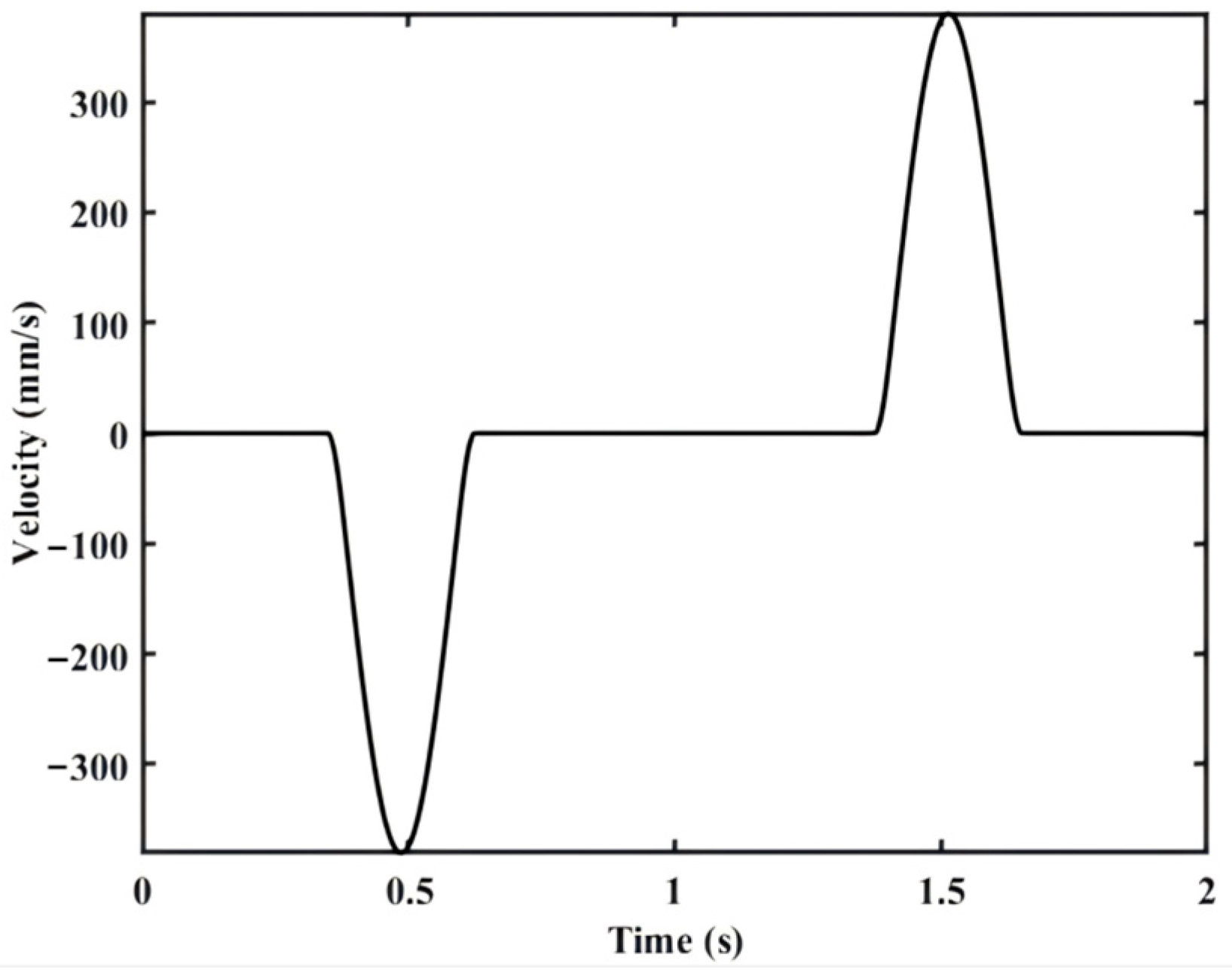
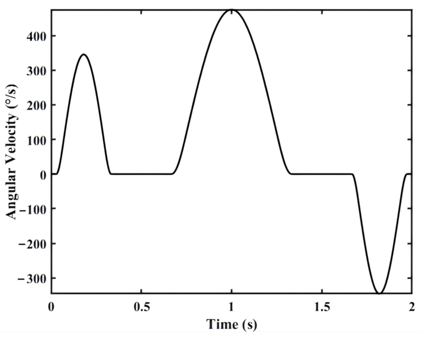
2.1. Theoretical Linear and Angular Velocities of the Manipulator
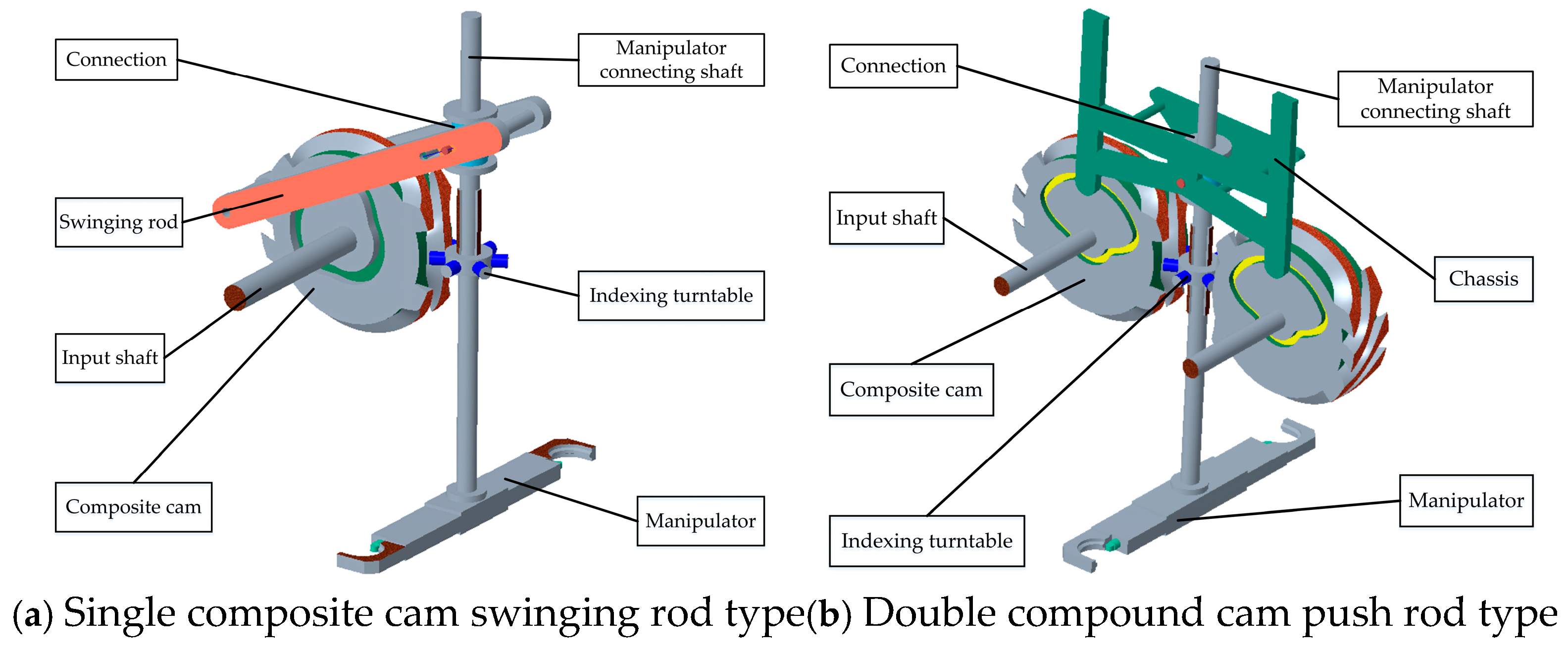
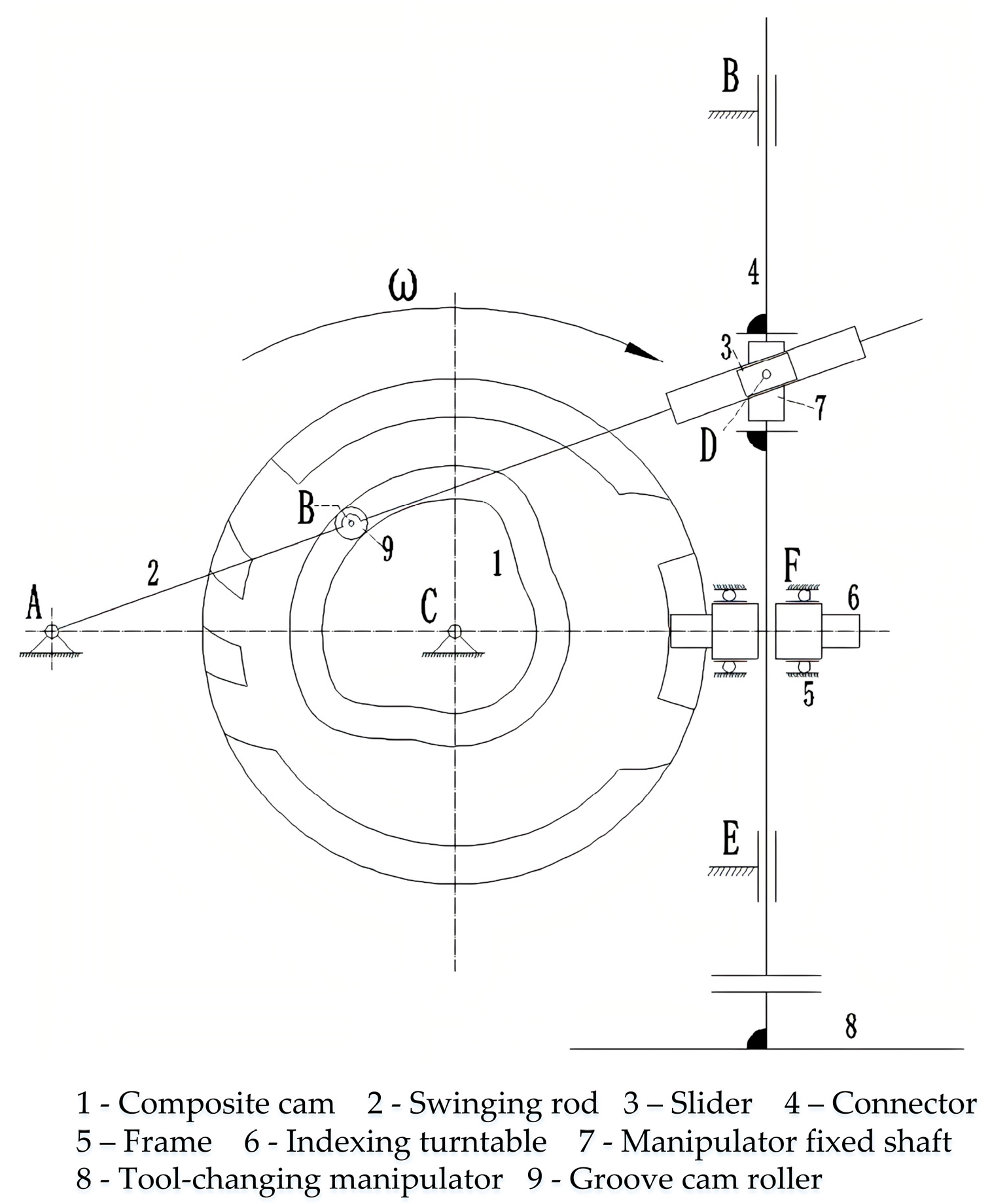
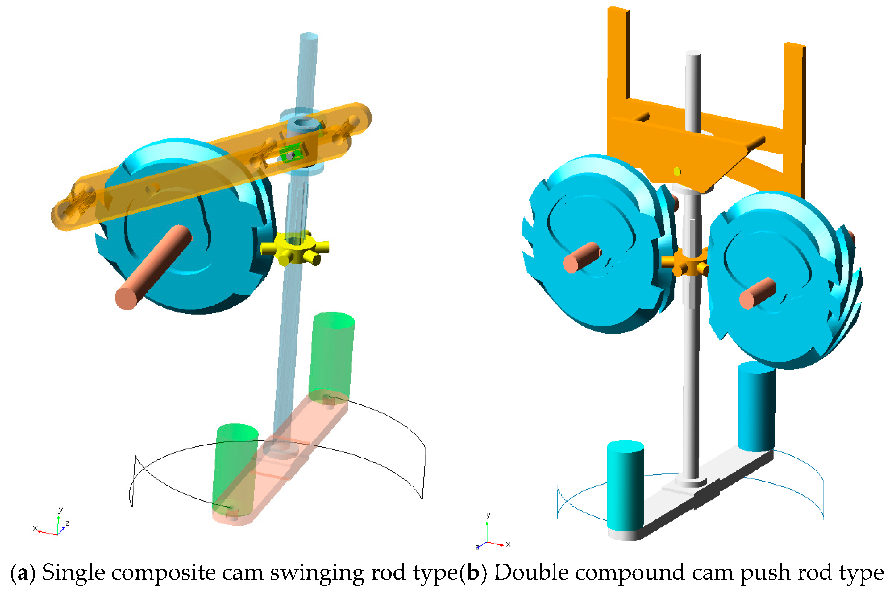
The manipulator typically performs both rotary and vertical linear motions. In this study, the linear stroke of the manipulator for both tool-changing mechanisms is set to 60 mm, with a tool-changing time of 2 s. These parameters are chosen based on practical application requirements and their relevance to simulation analysis. A 60 mm linear stroke meets the spatial demands of most CNC machine operations, while a 2 s tool-changing cycle ensures smooth transitions and balances stability with operational efficiency. Additionally, this parameter combination allows for the optimization of velocity profiles, effectively reducing inertial impacts and vibrations, improving the durability of cam and follower components, and providing a reliable basis for comparing the performance of different tool-changing mechanisms.
In order to reduce the impact of the cam-based tool changer mechanism during operation, this paper proposes a motion curve for the cam-based tool changer mechanism, designed based on an improved sinusoidal acceleration law. The theoretical linear velocity and angular velocity variation curves of the manipulator are derived from the motion curve of the mechanism, as shown in Figure 1 and Figure 2.
Figure 1 and Figure 2 illustrate the theoretical changes in the manipulator’s linear velocity and angular velocity over the 2 s tool change cycle. The linear velocity changes correspond to the manipulator’s straight-line motion during the stages of tool withdrawal, rotation, and insertion. By gradually accelerating and decelerating, the manipulator achieves smooth transitions between positions, reducing the impact on the cam and the follower. The angular velocity reflects the speed changes during the manipulator’s rotary motion. The gradual acceleration and deceleration ensure the smooth operation of the indexing plate arc cam mechanism and mitigate vibrations caused by inertia effects.
In Figure 1, the linear velocity curve exhibits a smooth progression through acceleration, constant speed, and deceleration. This behavior helps to reduce the inertial impact during tool withdrawal and insertion, improving motion stability and positioning accuracy. Similarly, the angular velocity curve in Figure 2 demonstrates smooth acceleration and deceleration, ensuring seamless transitions during indexing plate rotation and accurate positioning before tool insertion.

2.2. Solid Modeling

The modeling of the composite cam was completed using the software tools Creo 9.0 and Matlab R2021b. Based on the composite cam model and with reference to traditional manipulator tool changer mechanisms [16,17], the modeling of the single composite cam swinging rod type tool changer mechanism was completed. According to actual requirements, the modeling of the double composite cam push rod type tool changer mechanism was also completed. The specific structure is shown in Figure 3 below.
In the double composite cam push rod type tool changer, the right and left composite cams are identical in structure. However, during the assembly process, the left and right composite cams are installed in opposite orientations. During the tool change process, the left and right composite cams rotate in opposite directions at equal angular velocities [18,19]. The arrangement of the left and right planar cams prevents a significant bending moment from being generated on the slide frame arm while also partially offsetting the contact force exerted by the linear motion follower in the lateral direction. This reduces the impact on the slide frame follower to a certain extent.

3. Contact Force Analysis of the Swinging Rod and Push Rod

In different time periods, the push rod cam mechanism and swing rod cam mechanism were used for force analysis, and the construction of the pressure angle model and the follower contact force of the mechanical model were used to explore the push rod and swing rod follower contact force change rule.

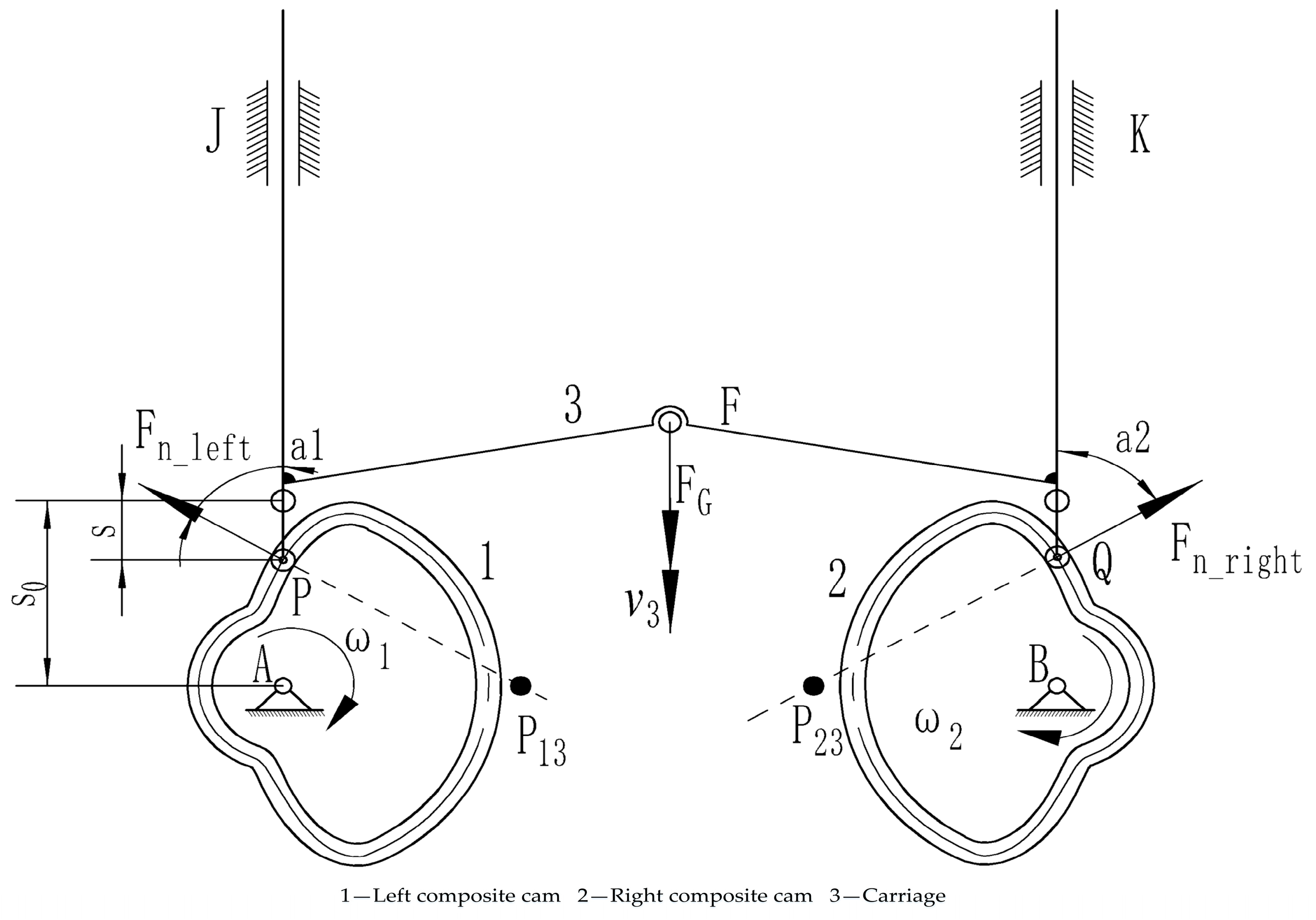
3.1. Pressure Angle of Cam Mechanism

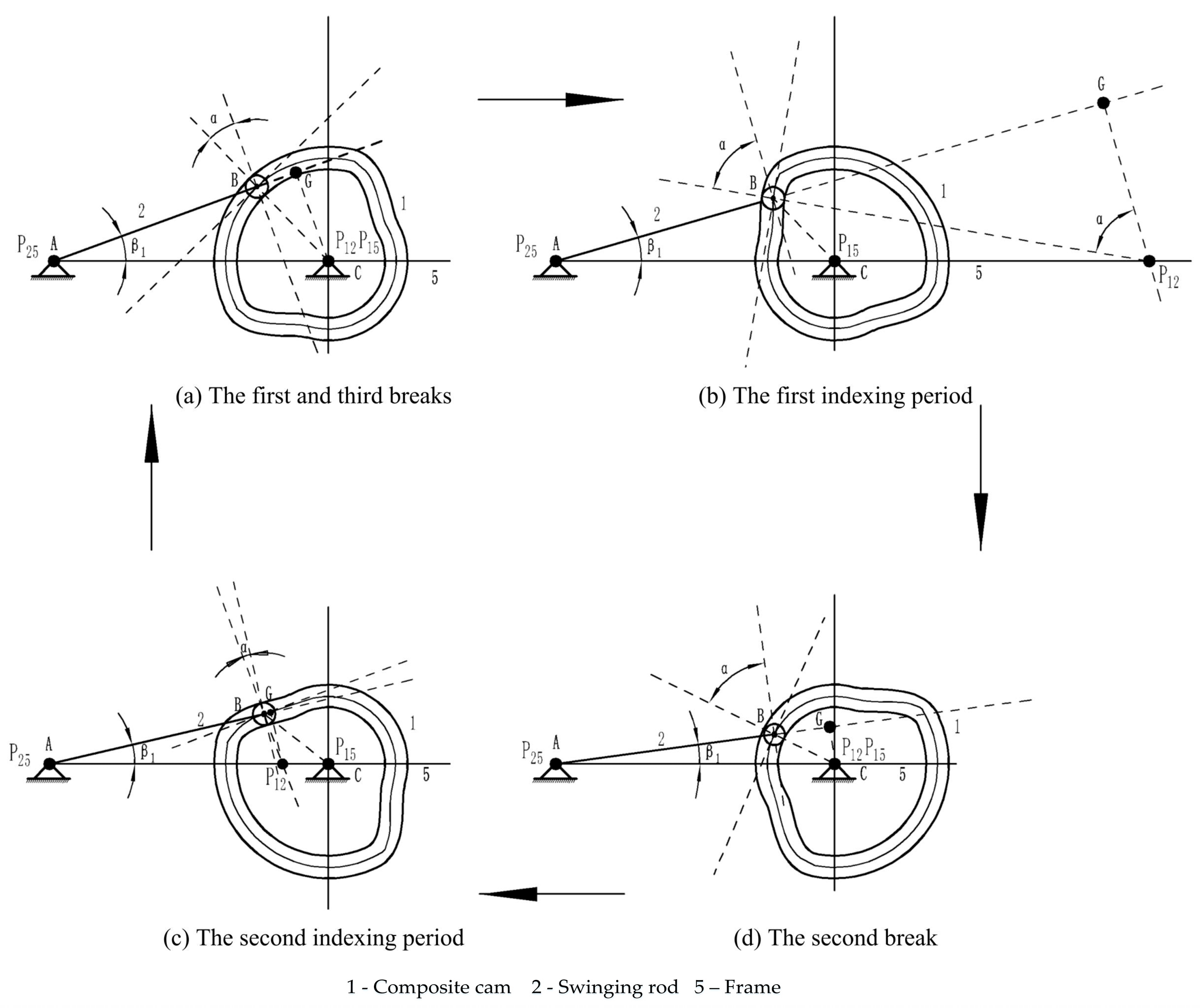
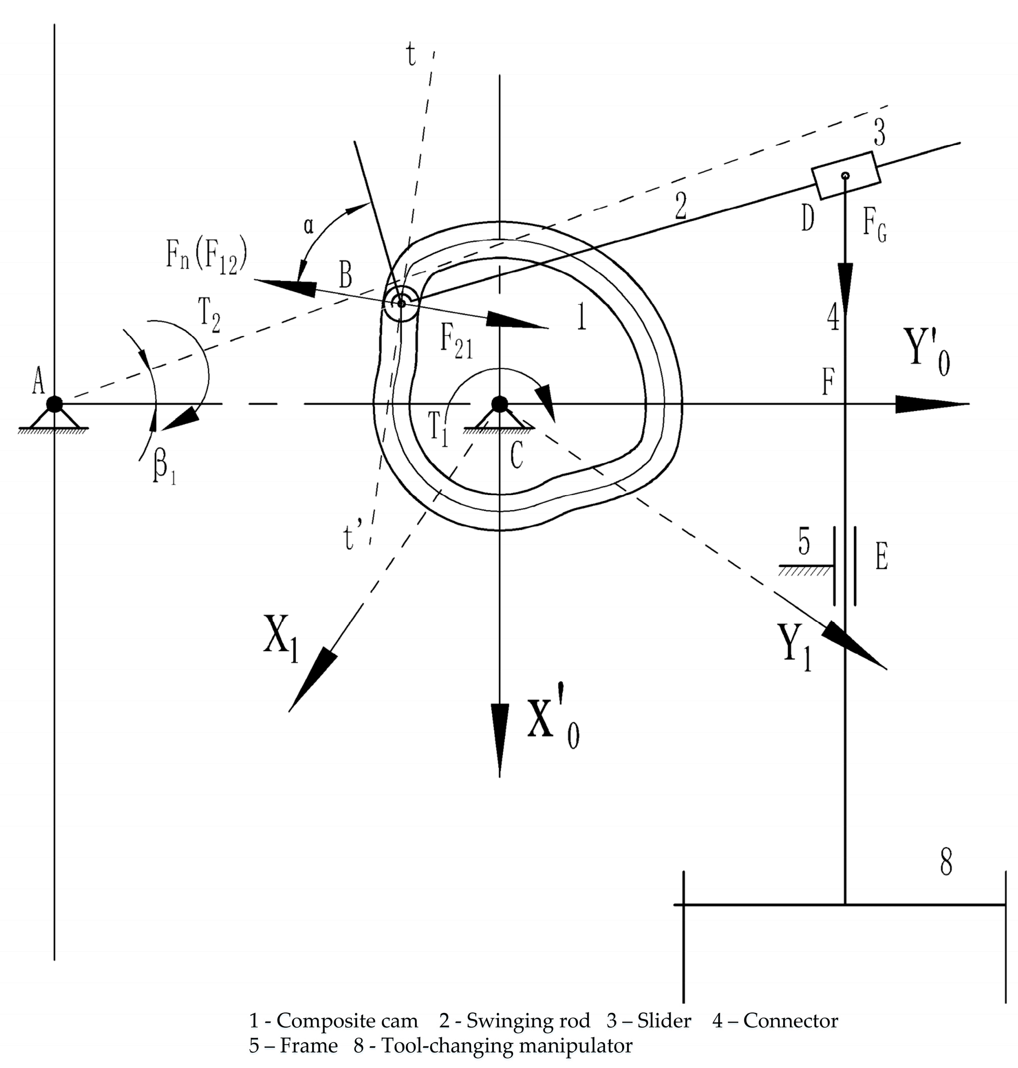
3.1.1. Analysis of Pressure Angle in Swinging Rod Groove Cam Mechanism

Figure 4 illustrates the basic structure of the single composite cam swinging rod tool change mechanism and the layout of its key components, including the composite cam, swinging rod, slide frame, and connectors, clearly reflecting the composition and working principles of the mechanism.
As illustrated in Figure 5 below, during the dwell period, the pressure angle of the mechanism remains constant. Conversely, during the indexing period, the pressure angle of the mechanism continuously changes with the operational dynamics of the mechanism [20].
For this mechanism, to identify the velocity instant centers corresponding to each member, the points P 12 , P 15 , and P 25 are first located in the diagram. P 12 represents the relative instant center of members 1 and 2, while P 15 and P 25 represent the absolute instant centers. The acute angle between the direction of the normal load at the contact point of the two members and the direction of linear velocity at the same point is the pressure angle of the mechanism. By drawing a line perpendicular to line AB through the velocity instant center P 12 , intersecting at point G, the pressure angle is determined as G P 12 B .
Taking Figure 5b, which represents the first indexing period, as an example, the following is obtained:
tan α = tan G P 12 B = L B G L P 12 B
From the geometric relationship illustrated in Figure 5b, the following is obtained:
L B G = L P 12 A cos β 1 L A B
L P 12 B = L P 12 A sin β 1
L P 12 A = L P 12 C + L A C
From the definition of the instantaneous center, the following can be obtained:
ω 1 L C P 12 = ω 2 L A P 12
By solving Equations (1)–(5), the pressure angle during the first indexing period is obtained as follows:
α = arctan cot β 1 L A B ( ω 1 ω 2 ) ω 1 L A C sin β 1
The same methodology may be employed to model pressure angle calculations for alternative time periods.
The pressure angle during the second indexing period is obtained as follows:
α = arctan [ cot β 1 L A B ( ω 1 + ω 2 ) ω 1 L A C sin β 1 ]
The pressure angle during the first and third breaks, as well as the second break, is as follows:
α = arctan ( L A C cos β 1 L A B L A C sin β 1 )
β 1 = arccos L A B 2 + L A C 2 r B C 2 2 L A B L A C
In Equation (9), r B C represents the curvature radius of the theoretical curve.

3.1.2. Analysis of Pressure Angle in Push Rod Groove Cam Mechanism

Figure 6 illustrates the basic structure of the double composite cam push rod tool change mechanism, highlighting the layout of its key components, including the cams, push rods, and manipulator, along with their functional relationships and spatial arrangement.
The same methodology can be applied to derive the pressure angle calculation model for the pushrod groove cam mechanism at each time interval. As illustrated in Figure 7, the pressure angles on the left and right sides of the cam mechanism are equal in magnitude.
In Figure 7, P 12 is the instantaneous center of velocity for component 1 and component 3, P 23 is the instantaneous center of velocity for component 1 and component 3,   S is the slider displacement, and S 0 is the initial distance from the slider contact point to the cam's rotational center.
The pressure angle of the swinging rod grooved cam mechanism is represented by the following equation
α 1 = First   and   second   indexing   periods : arctan [ v 3 ( s 0 + s ) ω 1 ] First ,   second   and   third   breaks : 0

3.2. Contact Forces of Followers

3.2.1. Contact Forces of Swinging Rod

In the following equations, m 1 represents the mass of the swinging rod, m 3 represents the mass of the slider, m 4 represents the combined mass of the connecting piece, manipulator connecting shaft, and manipulator, and m 5 represents the mass of the tool load.
As shown in Figure 8, the swinging rod (member 2) rotates about point A, with a length of L s . The rotation of this swinging rod can be considered as the rotation of a slender, uniform rod about its endpoint [21], and its moment of inertia can be determined from the relevant literature as
J A = 1 12 m 2 2 × L s 2 = 1 3 m 2 L s 2
Setting the upward vertical direction as positive, the following can be concluded from the above force analysis.
The center of mass of the swinging rod is located at the center of the swinging rod, and a normal load F n is applied at the point of contact in the direction perpendicular to the common tangent t t . The moving point D on the swinging rod is subjected to the gravitational forces from member 3, member 4, and member 6, where member 4 includes the manipulator and the lifting indexing shaft. The force acting on the moving point D on the swinging rod is vertically downward, with a magnitude of
F G = m 3 + m 4 + 2 m 5 g
According to the relevant literature on the motion dynamics of the swinging rod [22], the acceleration of the swinging rod can be calculated as
σ 2 = A β f ω 1 2 θ f
The forces and the input–output torque have the following relationship
J A σ 2 = F n cos α L A B F G L A D cos β 1
By solving Equations (11)–(14), the contact force calculation model of the rocker under load conditions is obtained as
F n = 1 3 m 2 L s 2 A β f ω 1 2 θ f + m 3 + m 4 + 2 m 5 g L A F L A B cos α

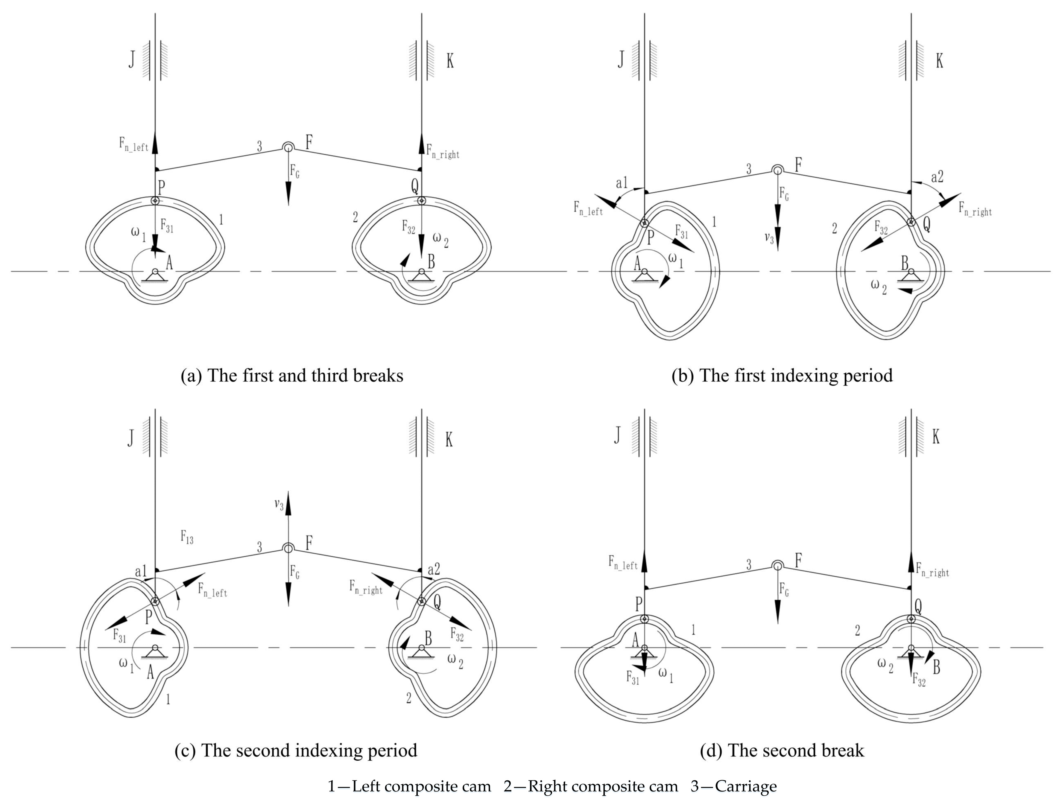
3.2.2. Contact Forces of Push Rod

In the following equations, m 3 represents the mass of the carriage, m 4 represents the combined mass of the connecting parts, manipulator connecting shaft, and manipulator, m5 represents the mass of the tool load, and ω 1 represents the angular velocity of the cam.
F G = m 3 + m 4 + 2 m 5 g
The acceleration of the rocker is
a 3 = A P f ω 1 2 θ f
As shown in Figure 9, the contact forces F n _ l e f t and F n _ r i g h t are equal in magnitude. According to Newton’s second law, the following can be concluded:
m 3 + m 4 + 2 m 5 a 3 = F n _ left cos α 1 + F n _ right cos α 2 F G
By solving Equations (16)–(18), the contact force calculation model of the pusher under load conditions is obtained as
F n _ left = F n _ left = m 3 + m 4 + 2 m 5 A P f ω 1 2 θ f + m 3 + m 4 + 2 m 5 g 2 cos α 1

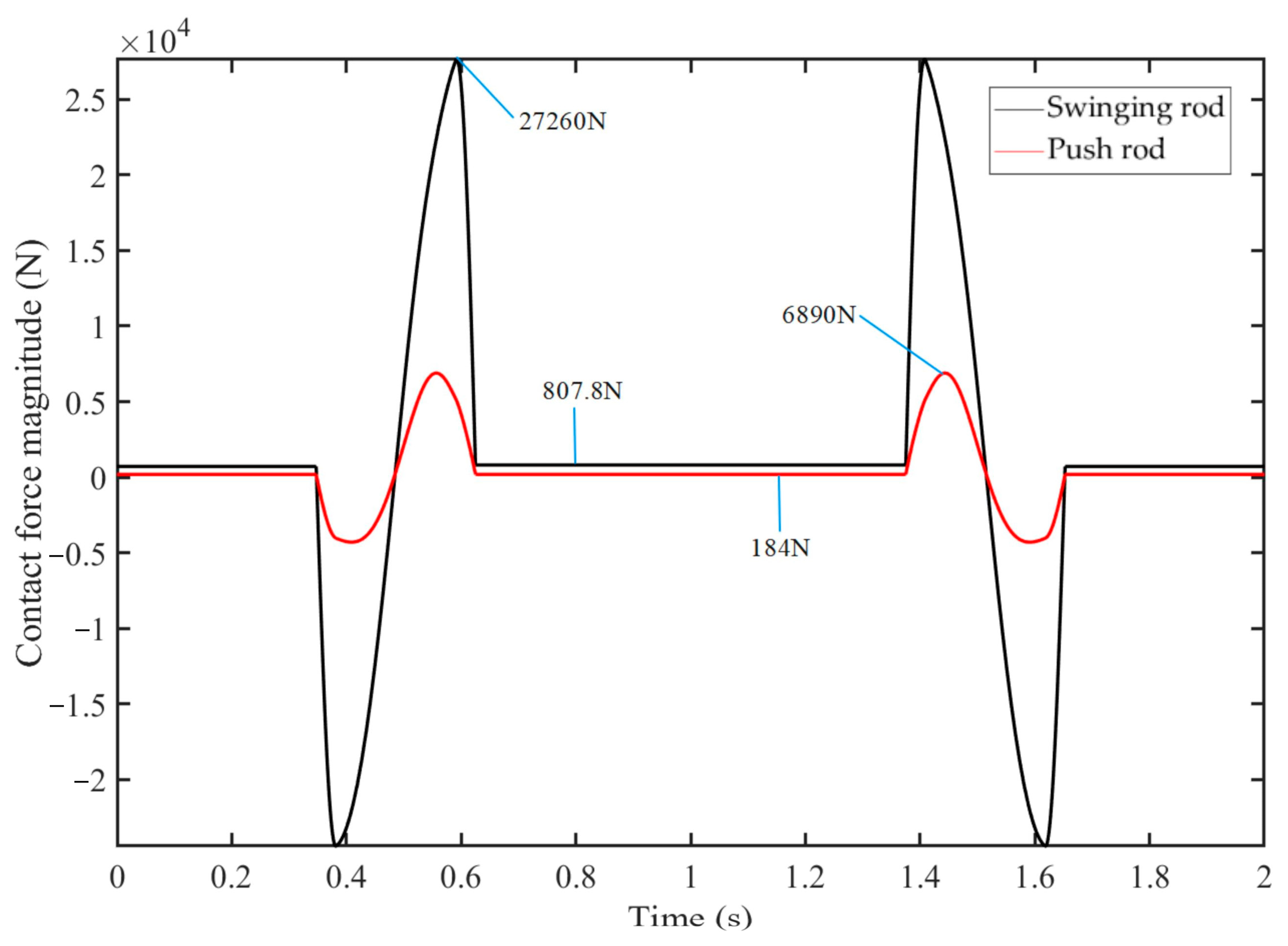
3.3. Quantitative Comparative Analysis

The dimensional parameters of the structure in the contact force calculation model, along with the speed and kinematic parameters, such as acceleration, were determined during the modeling process [23,24]. The mass parameters in the calculation model can be derived from the material’s density and the model’s volume.
Based on the previously derived pressure angle and contact force calculation models, namely Equations (6)–(8), (10), (11) and (19), the variation curves of the swinging rod and push rod contact forces during the tool change cycle were plotted using Matlab, as shown in Figure 10.
Figure 10 provides a clear comparison of the force characteristics of the swinging rod and push rod mechanisms during the tool-changing process. The red curve represents the contact force of the push rod, while the black curve represents the contact force of the swinging rod. The following is a detailed description and analysis of the four stages of the tool change process: tool withdrawal, rotation, tool insertion, and resetting.
During the tool withdrawal and insertion stages, the manipulator begins by gripping and lifting the tool from its original position or inserting it into the target location. In this process, the contact force of the swinging rod increases rapidly, reaching a peak value. Due to the impact of inertia, the theoretical contact force of the swinging rod is significantly large, with a peak of 27,260 N. In contrast, the push rod’s contact force during the same stages is noticeably smaller, at only 6980 N, indicating that the push rod mechanism exerts less impact on the cam.
In the rotation and resetting stages, the manipulator performs horizontal rotational movements to adjust the tool’s position. During these stages, the contact forces of both the swinging rod and push rod remain relatively stable without significant fluctuations. The theoretical contact force of the swinging rod is 807.8 N, while the push rod’s contact force is lower at 184 N.
Overall, the push rod exhibits lower contact forces compared to the swinging rod throughout the tool-changing process. This indicates that, under the conditions of consistent linear stroke and a system comprising the manipulator, connecting shaft, and tool load, the push rod mechanism imposes less impact on the cam during the tool-changing process. This reduction in impact helps enhance the stability and longevity of the mechanism by mitigating inertia-induced effects.

4. Dynamic Simulation Analysis of Two Types of Tool Changers

Based on the Adams simulation platform, single composite cam swing lever and double composite cam push rod tool changer multi-stiffness dynamics simulation models were established. Comparison and analysis of double composite cam push rod tool changer mechanism in the operation process of the dynamic characteristics of the tool changer manipulator.

4.1. Establishing the Simulation Model

In the simulation analysis, the tool load is simplified into a mass body model, as shown in Figure 11. This mass body model is used to simulate the dynamic characteristics of the tool load: during the intermediate stages (corresponding to tool extraction, rotation, and insertion), the tool load is assigned the appropriate mass and rotational inertia, whereas, during the initial and final stages (corresponding to tool pickup and resetting), the load mass and rotational inertia are set to zero. This simplified model effectively captures the dynamic behavior of the tool load during actual operations, ensuring the accuracy and reliability of the simulation analysis.
As shown in Figure 12, the 3D models of the double composite cam push rod type and single composite cam push rod type tool changer mechanisms, after simplification, were imported into the Adams mechanical system dynamics analysis software for simulation analysis. In accordance with the actual working conditions, appropriate materials are assigned to the components, and reasonable constraints are applied to the contact connections between the individual components.
Based on actual requirements, the input shaft speed is set to 180°/s in the simulation, ensuring a tool change time of 2 s. Following a review of the related literature, the number of steps is set to 1000 to ensure simulation accuracy.

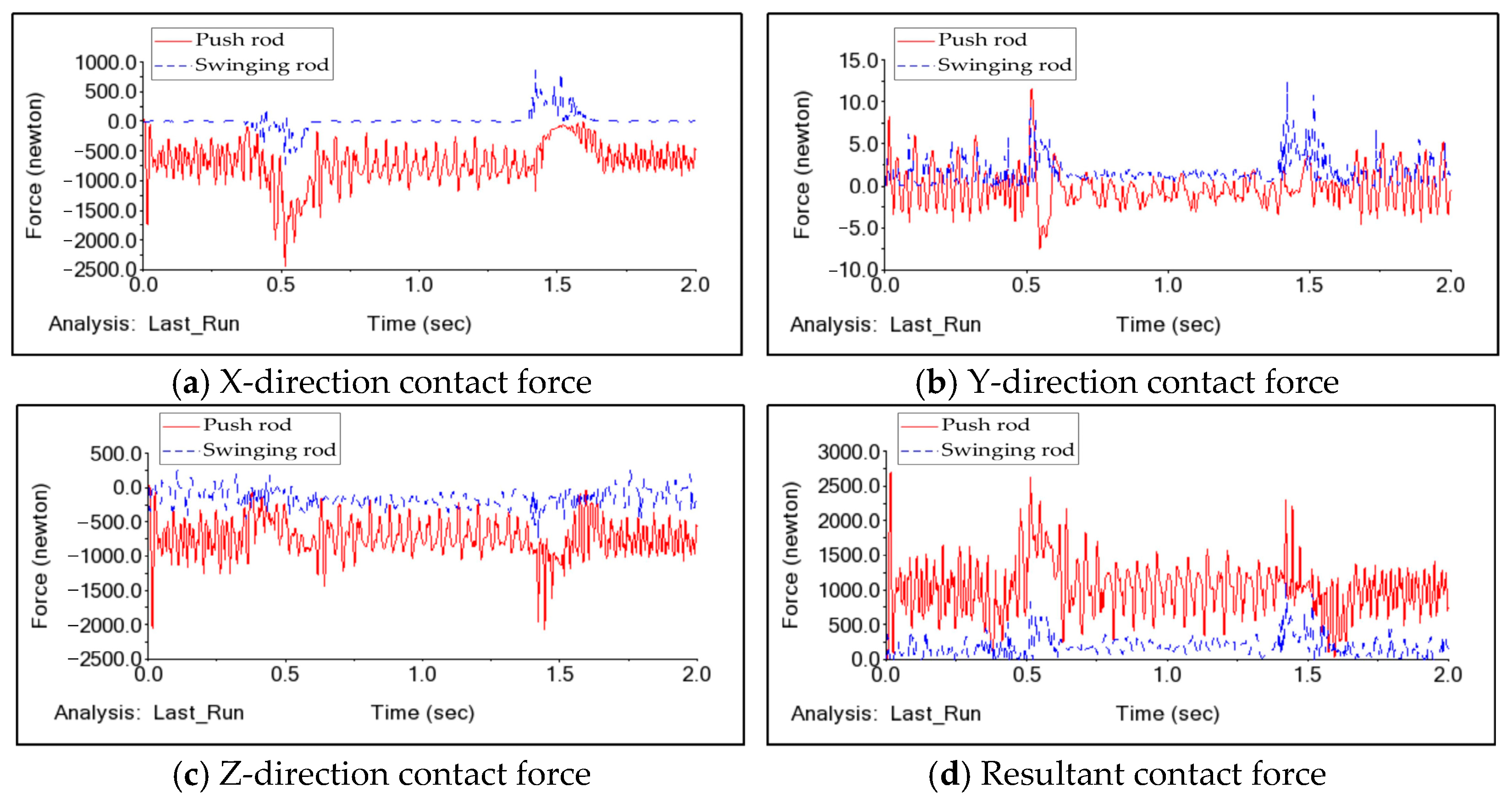
4.2. Comparative Analysis of Contact Forces Between Swinging Rod and Push Rod

The impact force on the cam and the follower contact force constitute a pair of action and reaction forces [25,26]. The magnitude of the contact force exerted by the follower reflects the magnitude of the impact experienced by the cam. In the simulation, the contact forces of the swinging rod and the push rod along the x, y, and z axes, as well as the combined force variation curves, can be obtained. These forces are then compared and analyzed, as shown in Figure 13.
In Figure 13, the red solid line represents the swinging rod contact force, while the blue dashed line represents the push rod contact force. As shown in the figure, the push rod contact force is lower than that of the swinging rod, indicating that the impact on the cam in the double composite cam push rod tool changer is less than the impact on the cam in the single composite cam swinging rod tool changer. This conclusion is consistent with the theoretical findings presented in the previous chapter.

4.3. Comparative Analysis of Manipulator Motion Smoothness

The degree of fluctuation in the manipulator’s acceleration can be used as an indicator of the smoothness of its movement.
In the simulation, the acceleration curves of the manipulator in the two types of tool changers during linear and rotary motion are obtained. The acceleration curves for both types of tool changer mechanism manipulators are subjected to FFT transformation, resulting in the manipulator’s acceleration amplitude–frequency curves. A comparison of the linear acceleration and rotary angular acceleration amplitude is made, as shown in Figure 14 and Figure 15. In the figures, the red solid line represents the single composite cam swinging rod type mechanism, and the blue dashed line represents the double composite cam push rod type mechanism.
As shown in Figure 14, during linear motion, the single composite cam swinging rod type mechanism shows acceleration fluctuation frequencies mainly between 0 and 250 Hz, with response amplitudes mostly in the range of 250–1500 and a peak of 1200 Hz. For the double composite cam push rod type mechanism, the frequencies are also in the 0–250 Hz range, but the peak amplitude is lower at 650 Hz.
As shown in Figure 15, during rotary motion, the single composite cam swinging rod type mechanism has a maximum frequency response amplitude of 650 Hz, while the double composite cam push rod type mechanism reaches 1100 Hz.
Overall, in the 25–60 Hz range, the double composite cam push rod type mechanism shows smaller acceleration fluctuations during linear motion compared to the swinging rod type. However, in the 60–250 Hz range, the push rod type mechanism has slightly larger fluctuations. For rotary motion, the push rod type mechanism generally exhibits greater angular acceleration fluctuations than the swinging rod type.
These results indicate that, compared to the single composite cam swinging rod type, the double composite cam push rod type achieves improved smoothness during the manipulator’s linear motion tool change process, providing certain advantages, though further optimization is needed. Conversely, during the rotary motion process, the tool change smoothness of the double composite cam push rod type is inferior to that of the single composite cam swinging type.
This suggests that the transition from a follower designed as a swinging rod to a push rod improves the smoothness and reduces the impact during the linear motion of the tool changer mechanism. However, the addition of the indexing plate’s curved cam mechanism does not provide a significant advantage in terms of smoothness and impact during the rotary motion.

4.4. Model Optimization

The double composite cam push rod tool change mechanism, initially designed to improve tool change smoothness, did not achieve the expected results in terms of stability and impact reduction. Instead, the additional curved cam mechanism introduced greater instability during the manipulator’s rotary motion, accelerated wear on the indexing disc, and reduced its service life. Based on the analysis, there is potential for further optimization, and removing the redundant curved cam mechanism has been identified as a promising direction [27,28,29,30].
As shown in Figure 16, a single composite cam push rod automatic tool change mechanism is derived by eliminating the unnecessary curved cam from the double composite cam structure. This optimization removes the curved surface cam ridge on the right side of the composite cam, resulting in a simplified design. The new configuration aims to improve stability during tool changes, reduce indexing disc wear, and enhance the overall reliability of the mechanism. Dynamic simulation and comparative analysis with the previous model confirm the effectiveness of this optimization.
The optimized model was simulated and analyzed again, and a comparison was made with the two types of tool changers mentioned in the previous section. The resulting comparison graphs are shown in Figure 17 and Figure 18. In the figures, the red solid line represents the single composite cam swinging rod type mechanism, the blue dashed line represents the double composite cam push rod type mechanism, and the green dotted line represents the single composite cam push rod type mechanism.
As shown in Figure 17, during linear motion, the single composite cam push rod type mechanism has significantly smaller acceleration fluctuations in the 40–80 Hz range compared to the double composite cam push rod type and in the 20–50 Hz range compared to the single composite cam swinging rod type. In other frequency ranges, the differences are minimal. Overall, the single composite cam push rod type mechanism offers better tool change smoothness during linear motion.
As shown in Figure 18, during rotary motion, the single composite cam push rod type mechanism generally has smaller angular acceleration fluctuations within the 0–250 Hz range compared to the double composite cam push rod type and is similar to the single composite cam swinging rod type. This indicates better tool change smoothness for the single composite cam push rod type mechanism during rotary motion.
In summary, the single composite cam push rod type mechanism demonstrates superior tool change smoothness during both linear and rotary motion compared to the other two mechanisms. It also experiences less impact on its followers and offers improved load-bearing capacity.

5. Experiments

Given the limitations of the experimental conditions, it was not feasible to construct the tool changer at its actual size. Therefore, the overall size of the experimental platform was scaled down to half of the original model, using the double composite cam push rod type tool changer mechanism to create a scaled experimental platform with a scaling factor of 0.5.

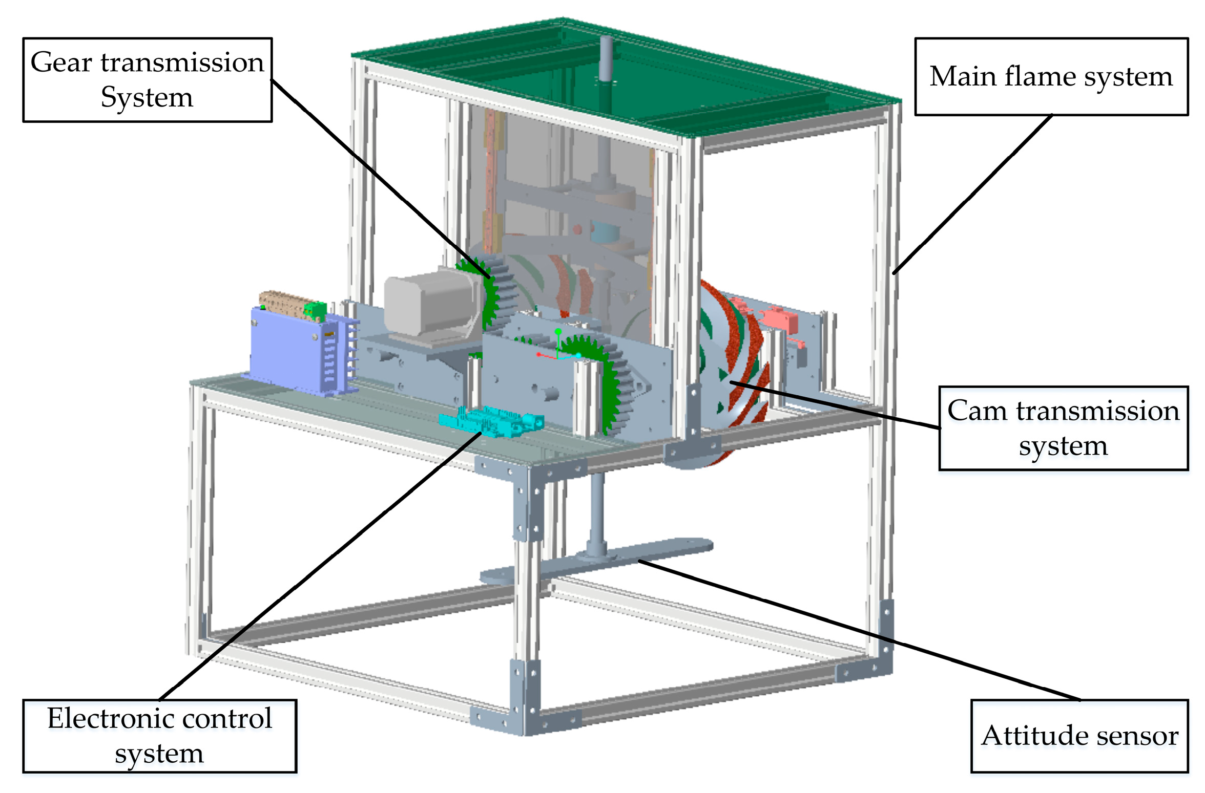
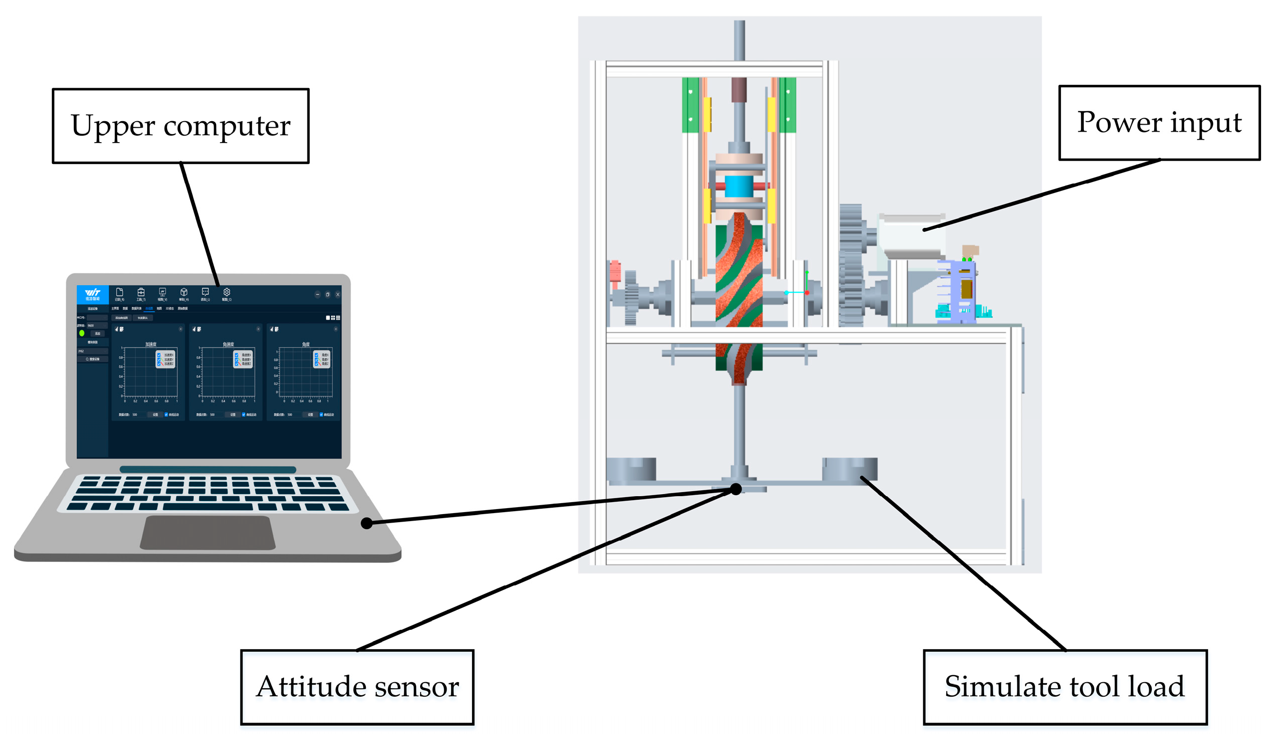
5.1. Design of Experimental Platform

As shown in Figure 19, the experimental platform consists of five main systems: the main frame system, gear transmission system, cam transmission system, electronic control system, and measurement system. The gear system ensures that the two camshafts are identical in size and rotate at a constant speed with opposite angular velocities in opposite directions.

5.2. Data Acquisition

Considering the connections between the manipulator and its components, as well as the spatial configuration, the attitude sensor is positioned at the center of the lower end of the manipulator. The center of the attitude sensor is aligned with the manipulator’s central hole to ensure that the sensor’s motion precisely corresponds to the manipulator’s movement. The attitude sensor measures angular position, angular velocity, and linear acceleration along the x, y, and z axes, with the z-axis corresponding to the manipulator’s up-and-down movement. After positioning the attitude sensor and connecting it to the computer via a data cable, the initial values of the sensor parameters can be observed on the upper computer. When the tool-changing system is activated, the automatic tool changer operates, and the manipulator begins a tool-changing cycle. The parameter changes observed on the upper computer are recorded for further analysis. A schematic diagram is shown in Figure 20.
The data processing procedure is structured to ensure accuracy and reliability at each stage of analysis. Initially, preliminary filtering is applied to the collected raw data to eliminate noise and outliers. This step is essential for enhancing data quality and ensuring that subsequent analyses are based on reliable inputs.
The decision to measure acceleration is crucial for accurately capturing the dynamic behavior of the manipulator during the tool-changing cycle. Acceleration data provides valuable insight into the forces and motion involved, helping to identify any irregularities or sudden changes in movement. By measuring acceleration, we can detect issues such as vibrations or instability that may not be evident from velocity or position data alone. This allows for a more comprehensive understanding of the manipulator's performance and ensures that potential problems, like jerky motion or excessive load, are detected and addressed early in the analysis. Moreover, acceleration data is integral throughout the design, modeling, simulation, and experimental phases, making it a more suitable parameter for comparison.
Following this, curve fitting is performed using Matlab or other advanced data processing software. This process fits the collected speed and acceleration data to generate precise variation curves for both linear and angular velocities, enabling a detailed characterization of the manipulator’s motion.
To further investigate the dynamic behavior of the system, frequency analysis is conducted using the Fast Fourier Transform (FFT) on the acceleration data. This analysis provides insight into amplitude characteristics across various frequency ranges, facilitating an assessment of the manipulator’s motion smoothness and dynamic performance.
Finally, results validation is carried out by comparing the processed data with simulation outputs and theoretical models. This validation step ensures the accuracy of the developed model and confirms the reliability and validity of the manipulator’s design.

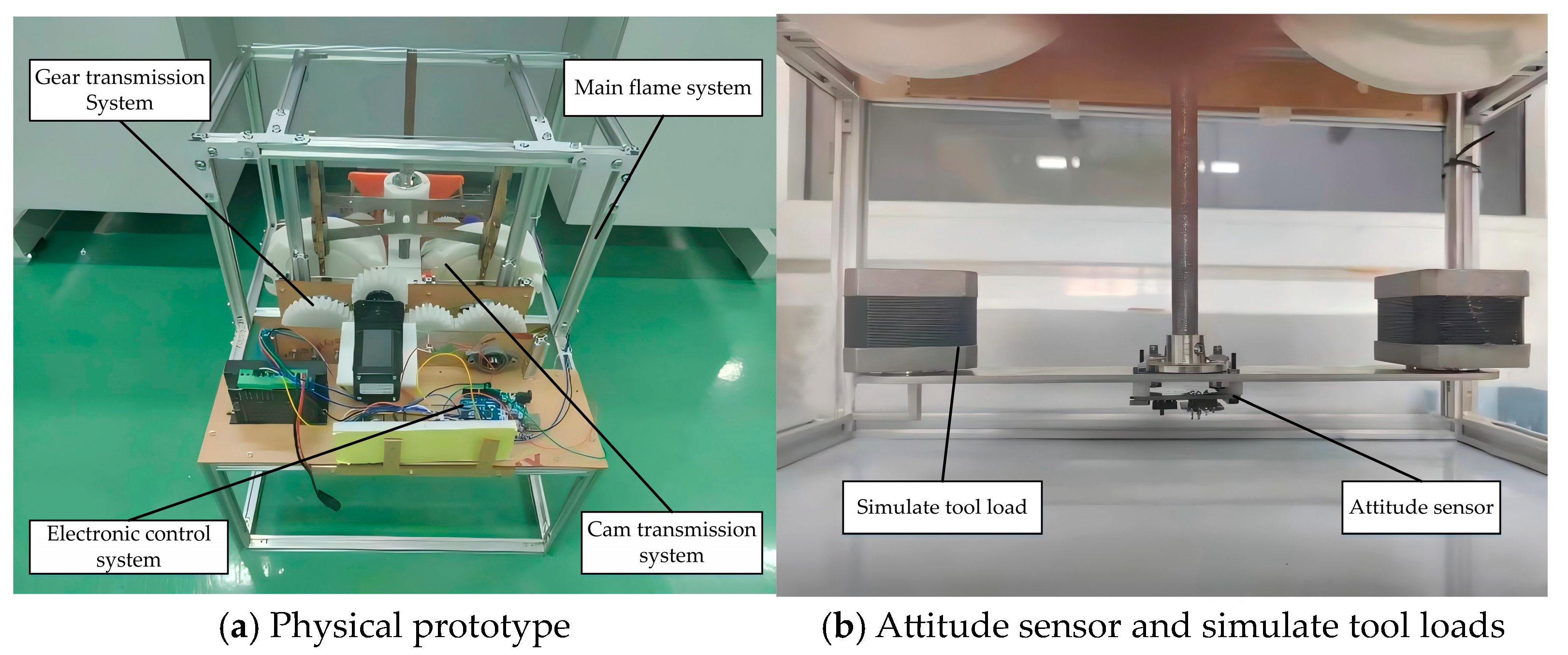
5.3. Physical Assembly

Based on the design of the experimental platform, the physical prototype was assembled, as shown in Figure 21.
During the experiments, objects with specific masses need to be selected to simulate the tool load. The selection of objects is primarily based on the existing conditions in the laboratory, the mass of the object, and assembly factors. In the laboratory, the 42-stepper motor model and mass are uniform in size, and the motor’s output shaft can be effectively assembled with both ends of the manipulator. Therefore, the 42-stepper motor was selected in the experiment to simulate the tool load, as shown in Figure 21b.

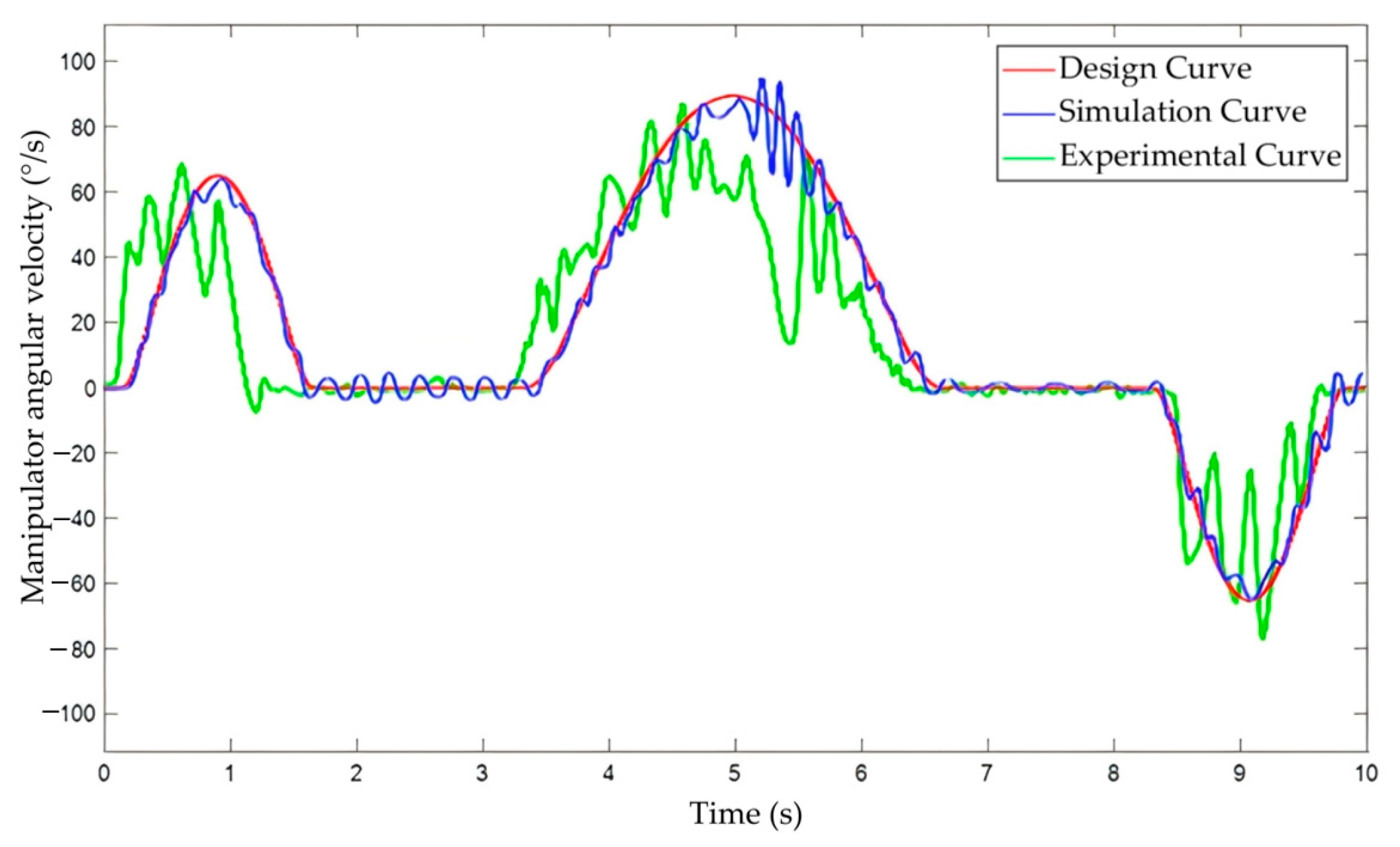
5.4. Data Comparison

Throughout the design, simulation, and experimental phases, the angular displacement of the manipulator remains constant. The primary distinction between these three scenarios lies in the differing tool change times. In this paper, the manipulator’s angular velocity is chosen as the link to establish a connection between the experimental, simulation, and design phases.
Due to the differences in tool change time, the theoretical relationship between the manipulator’s angular velocities is as follows:
V text = 0.2 V s i m u l a t i o n = 0.2 V d e s i g n
In Equation (20), V t e x t represents the angular velocity of the designed manipulator, V s i m u l a t i o n represents the angular velocity obtained through simulation, and V d e s i g n represents the design angular velocity of the manipulator.
Figure 22 provides a comprehensive comparison of the angular velocities of the manipulator during the design, simulation, and experimental phases, offering crucial insights into the dynamic performance of the push rod-type cam tool change mechanism. The design curve, serving as the theoretical benchmark, demonstrates ideal smoothness, reflecting the optimized theoretical characteristics of the tool change mechanism. The simulation and experimental curves were processed with a time axis scaled up by a factor of five and a velocity axis scaled down to one-fifth of the original, then overlaid onto the design curve for direct comparison. This approach vividly illustrates the relative relationships and discrepancies among the curves.
As observed in Figure 22, the simulation and experimental curves exhibit slight fluctuations around the design curve. These fluctuations can be attributed to multiple factors: first, manufacturing tolerances and assembly errors that influence the operational characteristics of the manipulator, and second, approximations introduced during the simplification of the simulation model. Such fluctuations partly reflect the complexity of real-world operating conditions. Nevertheless, the overall trends align closely with the theoretical design curve, further validating the accuracy of the theoretical relationship proposed in Equation (20).
Moreover, the deviations presented in the figure are minor, indicating a high degree of consistency between the theoretical design, simulation calculations, and actual operations of the push rod-type cam tool change mechanism. This consistency not only confirms the rationality of the mechanism’s design but also demonstrates the effectiveness of simulation analysis in performance prediction and the feasibility of experimental validation.
In summary, the analysis of Figure 22 clearly demonstrates that the dynamic characteristics of the push rod-type cam tool change mechanism are reliable under real-world operating conditions, meeting the design requirements for stability and precision. Additionally, the observed data fluctuations highlight the impact of inertial forces and suggest potential areas for improvement, providing valuable guidance for future optimization studies. This conclusion robustly validates the feasibility and reliability of the push rod-type cam tool change mechanism and establishes a solid theoretical and experimental foundation for further enhancing its dynamic performance.

6. Conclusions

This paper addresses the issues of amplified vibration errors and high impact forces in the traditional single composite cam swinging rod type tool changer by proposing an optimized double composite cam push rod type mechanism. The study focuses on the CNC machine tool changer manipulator’s up-and-down movement, comparing push rod and swinging rod solutions while providing design improvements and validation. The optimized single composite cam push rod mechanism demonstrates superior tool change stability and load-bearing capacity, making it suitable for high-stability and heavy-load applications in large-scale machining. This new approach offers valuable guidance for the further optimization and application of automatic tool-changing systems in CNC machines. The main conclusions are as follows:
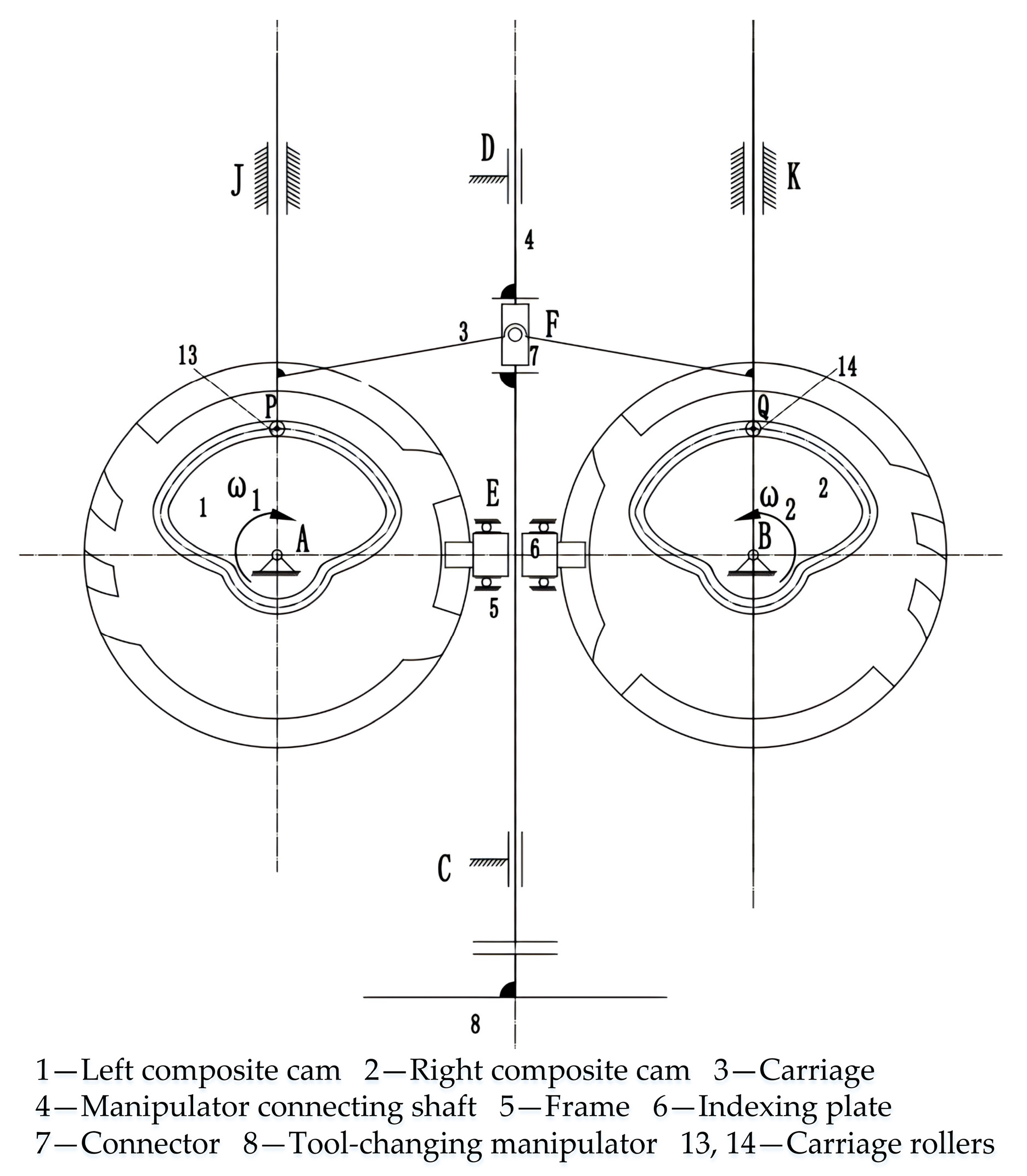
  • To solve the problems of amplified vibration errors and large impact forces in the single composite cam swinging rod type tool changer mechanism, a double composite cam push rod type tool changer was proposed.
  • Based on the meshing process between the push rod, swinging rod, and cam, a pressure angle model and contact force equation under load conditions were derived. Quantitative analysis using Matlab showed that the contact force between the push rod and cam is less than that of the swinging rod, reducing system impacts during tool changes.
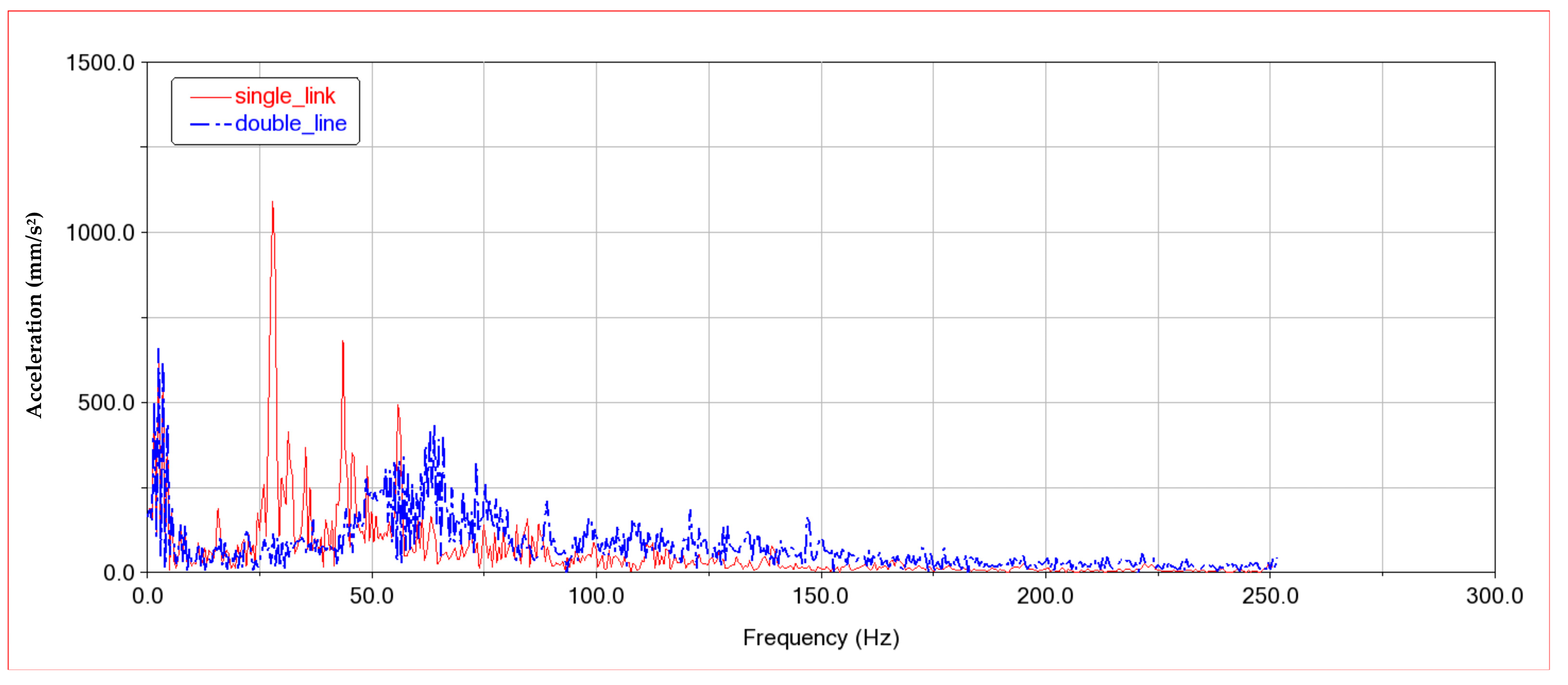
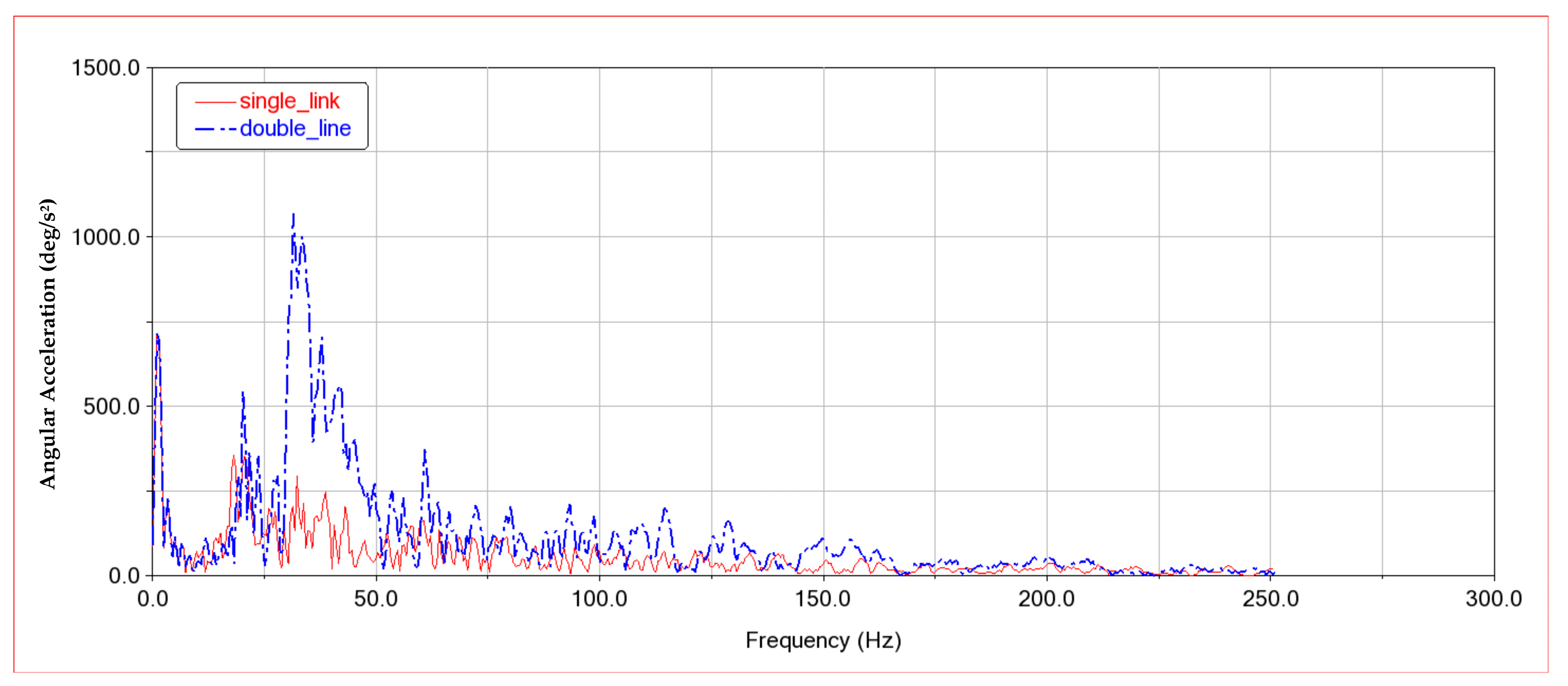
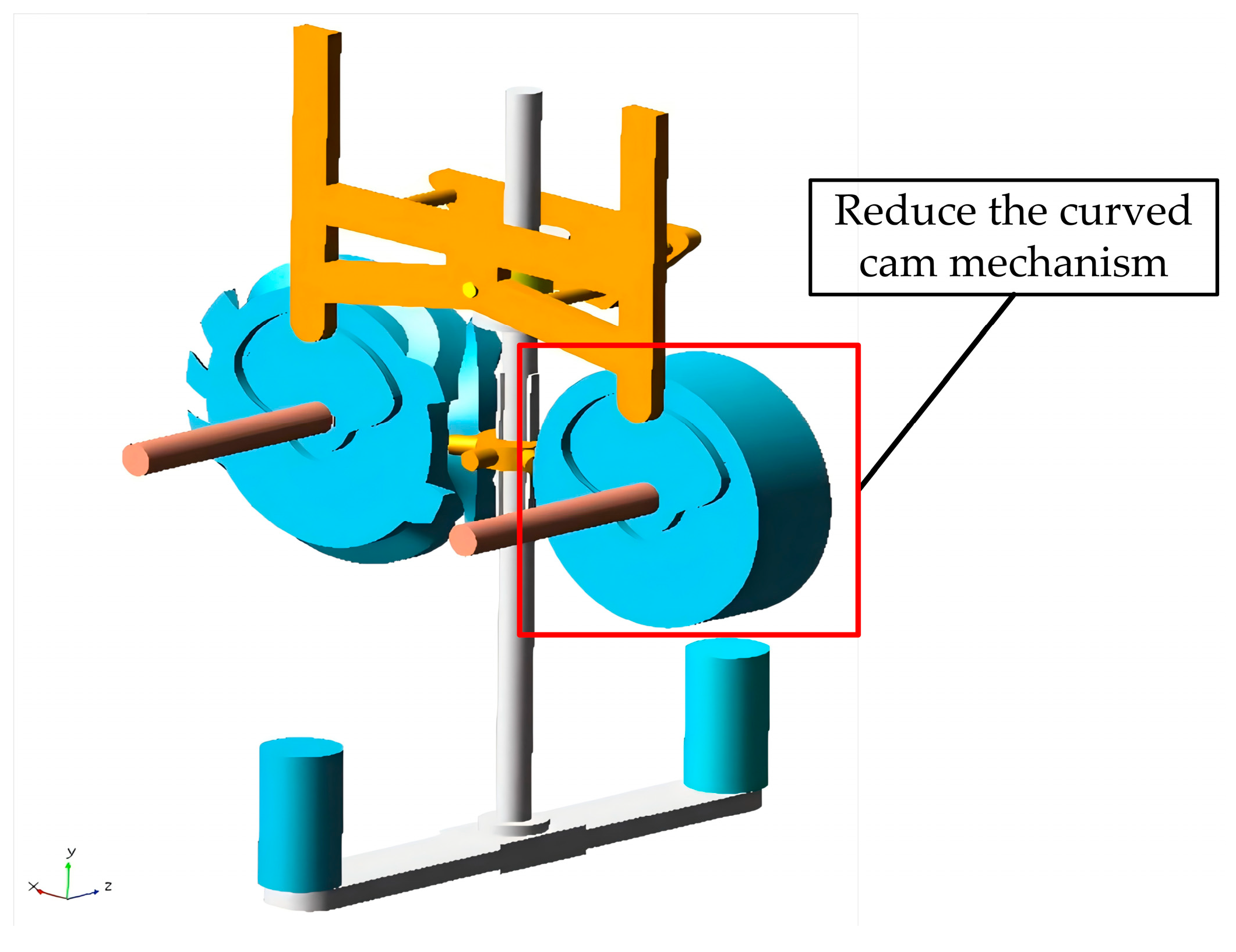
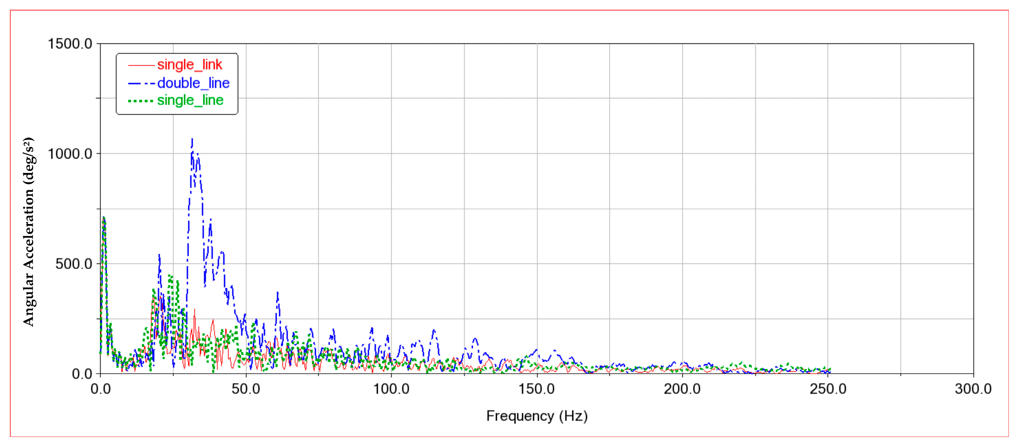
  • Dynamic simulations of the single composite cam swinging rod type and double composite cam push rod type tool changer mechanisms were conducted using the ADAMS simulation platform. Results indicated that the additional arc cams in the double composite cam structure reduced the stability of the manipulator’s movement and increased impacts on the indexing plate. The right-side arc cam was, therefore, removed, resulting in the optimized single composite cam push rod type mechanism, which improved tool change smoothness and reduced follower impact.
  • During experimental validation, a scaled experimental platform with a factor of 0.5 was built to collect data on angular position, angular velocity, and linear acceleration under load conditions. These data were processed using Matlab, validating the accuracy of the simulation and theoretical models and confirming the feasibility of the push rod type cam tool changer.
  • Compared to existing single composite cam swinging rod and double composite push rod mechanisms, the optimized single composite cam push rod type tool changer proposed in this study offers several advantages. The push rod type mechanism showed improved stability during both linear and rotary movements, significantly reducing acceleration fluctuations and minimizing system impacts. Additionally, due to structural improvements, the push rod-type mechanism is suitable for high load conditions, providing better load-bearing capacity and impact resistance than the swinging rod structure. While the optimized push rod structure compromises on compactness and takes up more space, it provides unique advantages in applications requiring high stability and load-bearing capacity.

Author Contributions

Conceptualization, X.Z. (Xinbo Zhang), X.Z. (Xiaobing Zhang), X.W. and Z.L.; methodology, X.Z. (Xinbo Zhang), X.Z. (Xiaobing Zhang) and Z.L.; software, X.Z. (Xiaobing Zhang) and Z.L.; validation, X.Z. (Xiaobing Zhang), X.Z. (Xinbo Zhang) and Y.Z.; formal analysis, X.Z. (Xinbo Zhang), X.Z. (Xiaobing Zhang) and X.W.; investigation, X.Z. (Xinbo Zhang), X.Z. (Xiaobing Zhang), W.Z. and Y.Z.; resources, X.Z. (Xinbo Zhang) and X.W.; data curation, X.Z. (Xiaobing Zhang), Z.L. and W.Z.; writing—original draft preparation, X.Z. (Xinbo Zhang) and X.Z. (Xiaobing Zhang); writing—review and editing, X.Z. (Xinbo Zhang), X.Z. (Xiaobing Zhang), X.W. and Z.L.; visualization, X.Z. (Xinbo Zhang); supervision, X.W.; project administration, X.Z. (Xinbo Zhang); funding acquisition, X.Z. (Xinbo Zhang). All authors have read and agreed to the published version of the manuscript.

Funding

The research subject was supported by the National Natural Science Foundation Sponsored Project (Project Approval Number: 52475257), the National Key Research and Development Program Project (Grant No. 2023YFB3406301), the Fund Project for Technological Field of National Defense Science and Technology Plan 173 (C-A44009, C-A55005, and C-B42004), the Marine Propulsion Research and Development (MPRD) Program (Grant No. MG20220203), the Longyan Xialong Engineering Technology Research Institute Science and Technology Specialist Workstation Project (Grant No. 2022MXN03) and the 2024 Xiamen Industry-University-Research Project “Research on EMC Control Strategy of CNC Machine Tool Control System” (Grant No. 2024CXY0404).

Data Availability Statement

All the data are shown in the figures of this paper.

Acknowledgments

The authors would like to thank the Xiamen University of Technology (XMUT), the Huaqiao University (HQU), the Xialong Engineering Technology Research Institute, and the Fujian Provincial Key Laboratory of Green Intelligent Cleaning Technology and Equipment for their support.

Conflicts of Interest

The authors declare no conflicts of interest.

References

  1. Li, J.; Tao, W.; Feng, T. Development Status and Key Technologies of Automatic Tool Changer. Mach. Tool Hydraul. 2013, 5, 174–176+160. [Google Scholar]
  2. Cai, X.; Che, W.; Chen, W. Research on parametric design technology of highspeed cam mechanism with oscillating follower. J. Graph. 2021, 42, 664–669. [Google Scholar]
  3. Chen, T. Modeling and Motion Simulation of the Globoidal Indexing CAM on Feeding, echanism Based on Conjugate Surface Theory. J. Sanmenxia Polytech. 2023, 22, 127–134. [Google Scholar]
  4. Li, J.; Rao, X.; Tang, M. Research of the Profile Surface Equation of Globoidal Indexing Cam Based on Unified Mathematical Expression. J. Mech. Transm. 2018, 42, 23–28. [Google Scholar]
  5. Chang, Z.; Zhang, C.; Yang, Y. Using envelop theory to generate meshing curved surface of spatial indexing cam. J. Mach. Des. 2000, 17, 10–11. [Google Scholar]
  6. Li, J.; Wang, X. Design of Cylindrical Indexing Cam and Circular Cone Rollers by MATLAB. Mech. Eng. Autom. 2015, 4, 78–79+82. [Google Scholar]
  7. Fang, Z.; Xu, J.; Cui, P. Simulation Design of Cam Mechanism Based on ADAMS and MATLAB. Coal Mine Mach. 2018, 39, 141–143. [Google Scholar]
  8. Zhao, S.; Fu, Y.; Lu, Q.; Zheng, L. Research on the Modeling and Kinematics Simulation of Globoidal Indexing Cam Mechanism Based on Creo and ADAMS. Mach. Des. Manuf. 2020, 2020, 111–114. [Google Scholar]
  9. Cao, P.; Luo, K.; He, X. Parametric Design of Globoidal Indexing CAM Mechanism and Secondary Development of NX. Int. J. Ind. Syst. Eng. 2021, 40, 1031–1036. [Google Scholar]
  10. Liu, P. Influence of Tapered Roller Bearing Clearance on Its Dynamic Characteristics. Master’s Thesis, Taiyuan University of Technology, Taiyuan, China, 2020. [Google Scholar]
  11. Sun, D. Dynamic Characteristics Analysis and Elastohydro-Dynamic Lubrication Simulation of Arc Cam Reduction Mechanism. Master’s Thesis, Hubei Automotive Industrial Institute, Shiyan, China, 2023. [Google Scholar]
  12. Cui, Y.; Zhang, H.; Huan, Y. Dynamic Characteristics Analysis of Circumferential Rod Fastening Rotor-Bearing System Considering Contact Stiffness. Power Gener. Technol. 2021, 42, 447–453. [Google Scholar]
  13. Guan, J. Research on Automatic Tool Changer and Fault Diagnosis of Machining Center Based on PMC. Master’s Thesis, Harbin Institute of Technology, Harbin, China, 2019. [Google Scholar]
  14. Liang, C. Dynamic Study of Rigid-Flexible Coupling for Cam-Type Automatic Tool Changer. Master’s Thesis, Shaanxi University of Science & Technology, Xi’an, China, 2017. [Google Scholar]
  15. Wang, G. Design of High-Speed and High-Reliability Disc Tool Change System. Master’s Thesis, Ningxia University, Ningxia, China, 2022. [Google Scholar]
  16. Wang, G. Research on High-Speed Machining Center Automatic Tool Changer. Master’s Thesis, Hebei University of Technology, Tianjin, China, 2015. [Google Scholar]
  17. Wang, S. Research on Motion Characteristics of Automatic Tool Changer. Master’s Thesis, Dalian University of Technology, Dalian, China, 2018. [Google Scholar]
  18. Yu, J.; Luo, L.; Shu, X.; Wu, Y.; Wen, C.; Hu, Q. Modeling and Profile Analysis of Globoidal Cam in Automatic Tool Changer. J. Mech. Transm. 2017, 41, 88–92. [Google Scholar]
  19. Stephen, S.; Cao, J.; Liang, J.; Zhang, C. Design of Offset Type Redundant Globoidal Cam. J. Mech. Transm. 2017, 41, 187–190, 202. [Google Scholar]
  20. Qin, X. Design of a Reversible Tool Storage Mechanism and Rotation Direction Recognition Device. Guangdong Polytech. Water Resour. Electr. Eng. 2024, 22, 48–51. [Google Scholar]
  21. Shames, I. Engineering Mechanics: Statics and Dynamics; PWS-Kent Pub. Co.: Boston, MA, USA, 2010. [Google Scholar]
  22. Sun, H.; Chen, Z.; Ge, W. Mechanics of Machinery, 8th ed.; Tsinghua University Press: Beijing, China, 2013; pp. 167–188. [Google Scholar]
  23. Cardona, S.; Zayas, E.; Jordi, L.; Catala, P. Synthesis of displacement functions by Bezier curves in constant-breadth cams with parallel flat-faced double translating and oscillating followers. Mech. Mach. Theory 2013, 62, 5–62. [Google Scholar] [CrossRef]
  24. Lu, X.; Wang, S.; Lu, Y.; Li, N.; Wen, C. Research on TBF distribution model of circular tool magazine and ATC. Int. J. Ind. Syst. Eng. 2019, 32, 382–404. [Google Scholar]
  25. Hou, J.; Feng, S. Research on Modeling and Processing Simulation of Ball Type Single Head of Globoidal Indexing Cam Entity. Modul. Mach. Tool Autom. Manuf. Tech. 2016, 2, 129–133. [Google Scholar]
  26. Gao, Y. Research of Mechanism of ADAMS Contact and Contact Friction. Automob. Appl. Technol. 2017, 6, 64–66+75. [Google Scholar]
  27. Gong, Z.; Jin, J. Design of the Cam in the Tool Changing Manipulator. Mach. Tool Hydraul. 2015, 14, 61–63+66. [Google Scholar]
  28. Li, J.; Feng, D. Contour Surface Design of Globoidal Indexing Cam. Mech. Eng. Autom. 2019, 3, 39–41. [Google Scholar]
  29. Zhao, H.; Fu, B.; Zhao, X.; Zhao, B. Parameterized design and dynamics simulation of globoidal indexing cam. Manuf. Autom. 2022, 44, 146–152. [Google Scholar]
  30. Wang, S.; Chen, T. Research of a CNC Machining Center Automatic Tool Changing Manipulator. Mod. Manuf. Technol. Equip. 2022, 58, 81–83. [Google Scholar]
Figure 1. Manipulator linear velocity.
Machines 12 00898 g001
Figure 2. Manipulator angular velocity.
Machines 12 00898 g002
Figure 3. Solid model of the cam tool change mechanism.
Machines 12 00898 g003
Figure 4. Schematic diagram of the single composite cam swinging rod tool change mechanism.
Machines 12 00898 g004
Figure 5. Analysis of pressure angle in swinging rod cam mechanism.
Machines 12 00898 g005
Figure 6. Schematic diagram of the double composite cam push rod tool change mechanism.
Machines 12 00898 g006
Figure 7. Analysis of pressure angle in push rod cam mechanism.
Machines 12 00898 g007
Figure 8. Force analysis of swinging rod groove cam mechanism.
Machines 12 00898 g008
Figure 9. Force analysis of push rod groove cam mechanism.
Machines 12 00898 g009
Figure 10. Comparison of quantitative analysis of contact force.
Machines 12 00898 g010
Figure 11. Tool load application.
Machines 12 00898 g011
Figure 12. Model Import.
Machines 12 00898 g012
Figure 13. Comparison of contact forces between swinging rod and push rod.
Machines 12 00898 g013
Figure 14. Comparison of the amplitude of linear acceleration of the manipulator.
Machines 12 00898 g014
Figure 15. Comparison of manipulator slewing acceleration amplitude.
Machines 12 00898 g015
Figure 16. Optimized model.
Machines 12 00898 g016
Figure 17. Comparison of linear acceleration amplitude of manipulator.
Machines 12 00898 g017
Figure 18. Comparison of the amplitude of rotary acceleration of the manipulator.
Machines 12 00898 g018
Figure 19. Three-dimensional model of the experimental platform.
Machines 12 00898 g019
Figure 20. System measurement framework.
Machines 12 00898 g020
Figure 21. Experimental platform.
Machines 12 00898 g021
Figure 22. Comparison and analysis chart.
Machines 12 00898 g022
Disclaimer/Publisher’s Note: The statements, opinions and data contained in all publications are solely those of the individual author(s) and contributor(s) and not of MDPI and/or the editor(s). MDPI and/or the editor(s) disclaim responsibility for any injury to people or property resulting from any ideas, methods, instructions or products referred to in the content.

