Article

Effect of Oil Film Radial Clearances on Dynamic Characteristics of Variable Speed Rotor with Non-Concentric SFD

1
School of Energy and Power Engineering, Beihang University, Beijing 100083, China
2
AECC Hunan Aviation Powerplant Research Institute, Zhuzhou 412002, China
3
Key Laboratory of Aero-Engine Vibration Technology, Aero Engine Corporation of China, Zhuzhou 412002, China
*
Author to whom correspondence should be addressed.
Machines 2024, 12(12), 882; https://doi.org/10.3390/machines12120882
Submission received: 28 October 2024 / Revised: 28 November 2024 / Accepted: 3 December 2024 / Published: 5 December 2024
(This article belongs to the Special Issue Power and Propulsion Engineering)

Abstract

:
Variable-speed aircraft engines require the power turbine rotor to operate stably within a wide range of output speeds, posing a challenge for rotor vibration reduction design. Non-concentric squeeze film dampers (NCSFDs) have been widely used in rotor vibration reduction design due to their simple structure. However, comprehensive research on the matching and applicability of NCSFDs under varying operating speeds is lacking. Therefore, this paper investigates the influence of oil film radial clearances on the dynamic characteristics of a variable-speed rotor system with an NCSFD, examining its suitability across variable speeds. This study introduces the principle of equivalent rotor dynamics similarity design, demonstrating good consistency between simulated and real rotor dynamic characteristics, with a radial clearance of 0.10 mm being deemed optimal. The vibration response variation in the rotor at a fixed speed within the range of 0.51 n to 1.0 n does not exceed 4 μm, and the vibration acceleration variation does not exceed 0.04 g, indicating a wide, stable operating speed range. This study can be helpful for the engineering design and vibration reduction design of variable-speed rotors in aircraft engines.

1. Introduction

The rotor is an important rotating part of turbine machinery such as motors, pumps, compressors, gas turbines, and aero-engines. Extensive research has been conducted on rotor dynamics. Many scholars, such as Tai and Li [1] and Jiang and Yuan [2], have studied the dynamics of turbomachinery rotors and achieved notable results. Compared with other turbomachinery, aero-engines are distinguished by their high speeds, intricate structures, and challenging operating conditions. Tilt-rotor aircraft employ tilt-rotor technology to seamlessly transition between helicopter and turboprop modes, harnessing the flight advantages of both. This innovation mitigates rotor drag during high-speed flight, enhancing speed and fuel efficiency for cruising [3]. With the increasing demand for aircraft engine economy and versatility, it is required that aircraft engines can operate stably over a wide range of speeds. Traditional fixed-speed aircraft engines can no longer meet the requirements, making variable-speed aircraft engine design a key technology for tilt-rotor aircraft [4]. To achieve stable operation of tilt-rotor aircraft over a wide range of rotational speeds, NASA applied the midline concept to design a four-stage variable power turbine and confirmed the feasibility of a variable speed power turbine with a 50% change in output speed [5,6]. Thus, it is important to carry out vibration reduction design of variable speed rotor systems and research on rotor stability at a wide range of working speeds.
SFDs are commonly used in the design of vibration-reduction structures for aircraft engines. With the development of aviation science and technology, many new types of SFDs have been developed and studied [7,8,9,10,11]. According to the presence or absence of centering elastic support, SFD can be divided into concentric SFD and NCSFD. Many scholars internationally have conducted extensive research on concentric SFD, including numerical modeling methods based on the Reynolds equation [12], multi-parameter optimization methods of the squeeze film damper-rotor system [13], influences of SFD on vibrations of the rotor system in aero-engines [14], dynamic characteristics of the rotor system with SFD [15,16], and so on.
Compared to concentric SFD, NCSFD takes up less space and has a simple structure. However, due to the lack of centering elastic support, its nonlinearity is stronger. Scholars have conducted extensive research on NCSFDs. In terms of theoretical analysis, Gunter [17] and Holmes and Dogan [18] have studied the mechanical mechanism and vibration reduction characteristics of concentric SFDs. Roberts et al. [19] studied the nonlinearity of concentric SFD through experiments and concluded that the greater the eccentricity and vibration amplitude, the more significant the nonlinear characteristics of SFD. Holmes and Box [20] and Holmes and Sykes [21,22] all have achieved fruitful results in concentric SFD vibration reduction technology through experimental and theoretical research and found that the oil film force of SFD has highly nonlinear characteristics. Bai et al. [23] conducted analysis and experimental research on the response of SFD rotor systems with concentric structures under sudden unbalance; Xia and Meng [24] studied the nonlinear and non-coordinated response of a flexible rotor system with NCSFD. Cui et al. [25] established a three-dimensional unsteady cavitation flow field numerical model and calculated and analyzed the cavitation flow field characteristics of NCSFD. Chen et al. [26] calculated the steady-state unbalanced response of a rigid rotor supported by an SFD without a centering spring. Andres and Seshagiri [27] and Andres [28] studied the influence of structural parameters such as fuel supply groove, static eccentricity, and end seal on the dynamic characteristics of NCSFD by a bidirectional actuator. Jawaid [29] studied the bifurcation phenomenon of flexible rotor response in squeeze film dampers without centering springs. In terms of experimental research. Zhu et al. [30] conducted a comparative experiment on the vibration reduction characteristics of concentric and NCSFDs under different unbalanced sizes and oil film radial clearances. Feng et al. [31] carried out a comparative experimental study on the vibration reduction characteristics of concentric and NCSFDs on a low-pressure equivalent rotor. As for the vibration data processing of the rotor system, there are numerous related studies. Among them, Chauhan et al. proposed the evolutionary algorithm and applied it in rotor bearing defect identification [32,33,34]. The results showed that within a smaller range of unbalance, the vibration reduction effect of NCSFD is better.
In summary, current research mainly focuses on the vibration reduction characteristics and mechanism analysis of NCSFDs, and the research targets mainly Jeffcott or laboratory simple rotor models. Furthermore, there is little theoretical and experimental research on the rotor system of aero-engines with NCSFDs. Therefore, additional research is needed on the dynamics of variable-speed rotor systems with NCSFDs and the suitability of NCSFDs across a wide range of operating speeds. Addressing the need for vibration reduction design and stability research for variable-speed rotor systems, this article undertakes simulation-based rotor design for variable speeds and analyzes the impact of different oil film radial clearances on the dynamic characteristics of NCSFD rotor systems. After theoretical analysis, reasonable oil film radial clearances are selected and experimentally verified. Based on the optimized oil film radial clearances, a wide-speed domain experimental study was conducted on the rotor system to verify the compatibility and applicability of NCSFD with variable-speed rotors. These findings can contribute to the engineering design and vibration reduction efforts for aircraft engine variable-speed rotors.

2. Equivalent Rotor Design

2.1. Design of the Equivalent Rotor

A certain variable speed rotor has a complex structure and high working speed. The risk and cost of conducting experiments directly using real rotors are high. To reduce the development risk and cost, a full-size (1:1 ratio) simulated rotor is designed based on the principle of dynamic similarity design for conducting experimental research. To minimize the testing risk and ensure that the research results can be used for the structural design of the real rotor, the design principle of an equivalent rotor is proposed as follows:
(1)
The main structures, such as the fitting relationship between the inner ring of the bearing and the shaft, turbine disk and shaft, connection method, axial preloading method, support span, support method, support stiffness, and bearing lubrication method, were consistent with the real rotor.
(2)
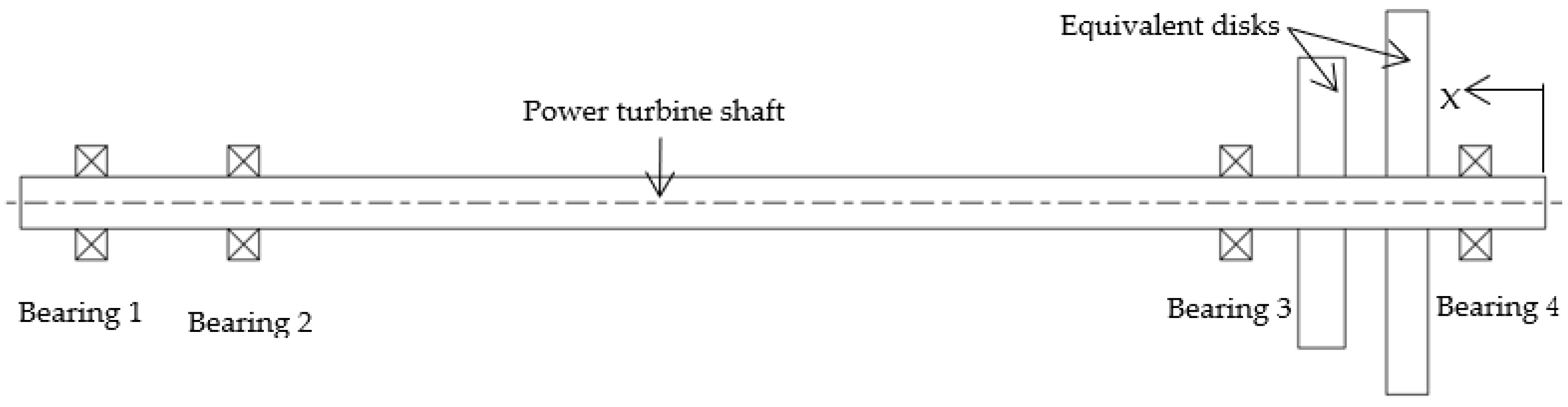
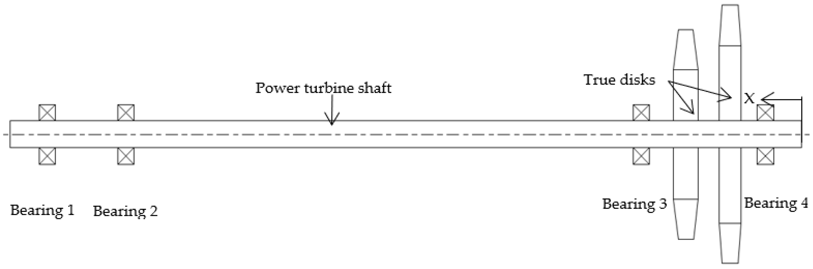
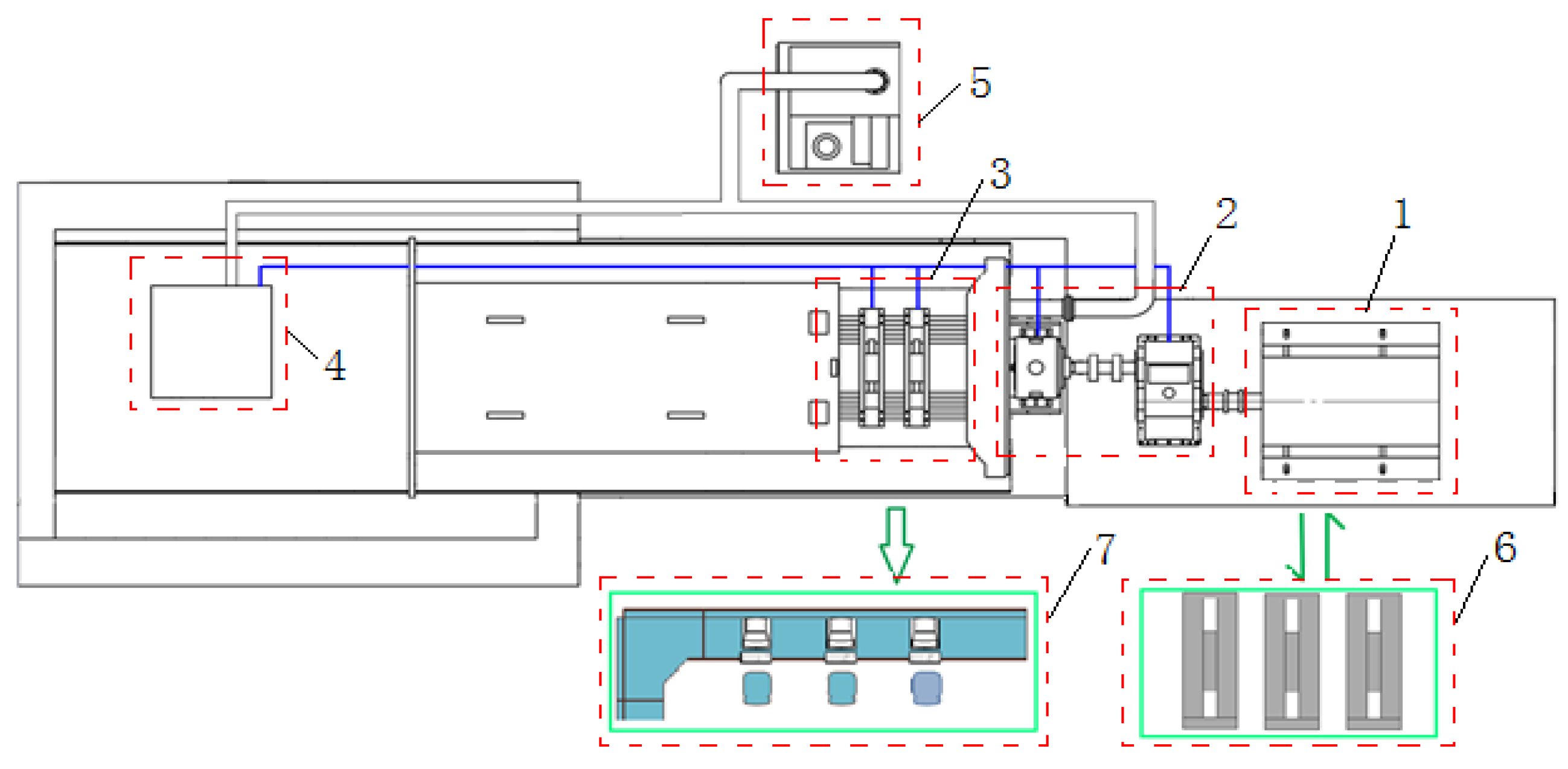
The equivalent power turbine disks adopt an equivalent disk structure, and its inertia parameters, such as mass, center of mass, and moment of inertia, are consistent with those of the real power turbine disks. At the same time, while ensuring that the strength of the power turbine equivalent disk meets the requirements, the structure was simplified, and the blade, mortise, and groove structures of the real wheel disk were removed. The rotor structure shown in Figure 1 was mainly composed of a power turbine shaft with a hollow structure, two-stage turbine disks, and four bearings. The Bearing 1 is a ball bearing, and the others are all roller bearings. Moreover, the Bearing 2 adopts an NCSFD structure, as shown in Figure 2.
The main structural parameters of the rotor are shown in Table 1.

2.2. Comparison Between Equivalent and Real Rotor

Compared with the real rotor (as shown in Figure 3), the simulated rotor only uses simulated disks, and the rest of the structure is the same. The comparison of the main inertial parameters of the disks between the two is shown in Table 2.
Compared with the real disks, the equivalent disks are 1.49% lighter, with a center of mass axial position deviation of 3.37% and a rotary pattern deviation of 0.3%. The deviation is relatively small.
Additionally, dynamic characteristic calculation models of both equivalent and real rotors were established by commercial software SAMCEF/ROTOR(V1.0) based on the finite element method. A comparative analysis of the first three orders of critical speeds and mode shapes was conducted with the support stiffness in Table 3, and the results were shown in Table 4 and Table 5. In Table 4, n represents the working speed of the rotor.
The errors between the first three-stage critical speeds of the equivalent rotor and the real rotor are all within 4%, and the first three-order mode shapes are basically the same for the two rotors. The results indicate that the dynamic characteristics of the equivalent and true rotors have good consistency, and the equivalent rotor reflects the dynamic characteristics of the true rotor well.

3. Dynamic Characteristic Analysis

3.1. Rotor Motion Equation

Ignoring the axial motion of the rotor, considering the gyroscopic moment, and considering the forces and unbalanced forces at each support as external forces, the rotor motion equation can be written as:
M u ¨ + G u ˙ + K u = F 1 + F 2
where M, G, and K, respectively represent the inertia matrix, gyroscopic matrix, and stiffness matrix; F1 represents the unbalanced force caused by the rotor imbalance, acting on the center of mass of the rotor; and F2 represents the supporting reaction force at the support points, acting on each support point.
Using N as the internal degree of freedom and J as the interface physical degree of freedom, the dimensionality of the rotor system is reduced by the fixed interface mode synthesis method [35,36], and then motion differential equations for the rotor system are established, as shown in Equation (2):
M ¯ N N M ¯ J N M ¯ N J M ¯ J J q ¨ N u ¨ J + G ¯ N N G ¯ J N G ¯ N J G ¯ J J q ˙ N u ˙ J + K ¯ N N 0 0 K ¯ J J q N u J = F ¯ 1 + F ¯ 2
where M ¯ , G ¯ , K ¯ , and F ¯ are the inertia matrix, gyroscopic matrix, stiffness matrix, and modal force of the reduced modal space, respectively, and q is the displacement in the modal space.

3.2. Nonlinear Analysis

Due to nonlinear stiffness, damping, and non-harmonic periodic or random excitations, the rotor exhibits nonlinear characteristics. This chapter of the paper mainly studies the nonlinear characteristics of the rotor when the oil film clearance is different.
To study the influence of oil film radial clearances on the nonlinear response characteristics of the rotor system, the NCSFD oil film radial clearance at Bearing 2 can be changed to 0.05 mm, 0.10 mm, and 0.15 mm, respectively, while the stiffness damper of other bearings remains unchanged. The response of the rotor system can be obtained by solving Equation (2), and the bifurcation diagram of the rotor response under different oil film radial clearances is shown in Figure 4.
As shown in Figure 4, the rotor response exhibits obvious nonlinear characteristics due to the NCSFD, and the bifurcation pattern under different oil film radial clearances is generally similar: at low speeds, the rotor exhibits “single period motion,” then undergoes brief bifurcation and double period bifurcation, gradually entering “chaotic motion” and finally returning to “single period motion.” However, the response bifurcation points are different because of different oil film radial clearances, and there are also differences in the specific speed range of areas such as “single cycle motion” and “chaotic motion”.
In addition, compared to smaller oil film clearances (taking c = 0.10 mm as an example), when the oil film clearance is larger (c = 0.15 mm), the rotor exhibits a phenomenon of bifurcation again after returning to “single cycle motion” at high speeds (1.0 n, where n is the working speed of the rotor), and the frequency components are more complex. Therefore, to prevent unfavorable vibration characteristics caused by the pronounced nonlinearity of the rotor at elevated speeds, which may induce multi-frequency vibrations and impact the rotor’s lifespan, it is advisable to keep the oil film clearance value of the NCSFD within reasonable bounds. The Poincaré section and spectrum at a speed of 1.0 n are shown in Figure 5 and Figure 6.

3.3. Critical Speeds and Vibration Shapes

The stiffness of the support is mainly based on the oil film stiffness when using NCSFD at Bearing 2. According to the short bearing theory [37], the formula for calculating the oil film stiffness is as follows:
K 0 = μ R L 3 C 3 2 Ω ε 1 ε 2 2
where C is the oil film thickness, R is the journal radius, L is the oil film length, and μ is the viscosity of the lubricating oil ( μ = ν ρ ) ν is the kinematic viscosity of the lubricating oil, ρ, and ε are the density of the lubricating oil and eccentricity, respectively, and Ω is the rotational speed. The different stiffness of Bearing 2 with different oil film radial clearances is shown in Table 6. The calculated critical speed and vibration mode of the first three orders of the rotor with different oil film radial clearances are shown in Table 7 and Table 8, respectively.
The critical speed margin represents the range of difference between the operating speed of the rotor and the critical speed and is used to measure the safety of the rotor during operation. Its calculation formula is as follows:
Critical speed margin = ((Critical speed−Operating speed)/Operating speed) × 100%
From the results in Table 7 and Table 8, as the oil film clearance continues to increase, the first three critical speeds of the rotor all move forward, and the degree of bending of the first three mode shapes also increases accordingly. As the oil film clearance gradually increases, the oil film stiffness of the support decreases, causing the transition of support from a “rigid support” to an “elastic support.” Additionally, the bending degree in the middle of the rotor shaft is the largest. Thus, in the experimental study in Section 4, the displacement measurement points were arranged in the middle of the rotor (see Figure 7 and Figure 8).
Based on the above analysis results, considering both the critical speed margin and the requirements for the rotor to operate within a wide range of speeds, it is more appropriate to choose 0.10 mm for the oil film clearance from a theoretical analysis perspective. Next, we will verify it from an experimental perspective.

4. Experimental Research

To study the influence of different oil film radial clearances on the dynamic characteristics of the NCSFD rotor system, the oil film radial clearances were controlled by controlling the clearance between the bearing seat and the outer ring of the bearing (see Figure 2). Three sets of bearing seats were processed (with oil film radial clearances given as 0.05 mm, 0.10 mm, and 0.15 mm) for experimental research.

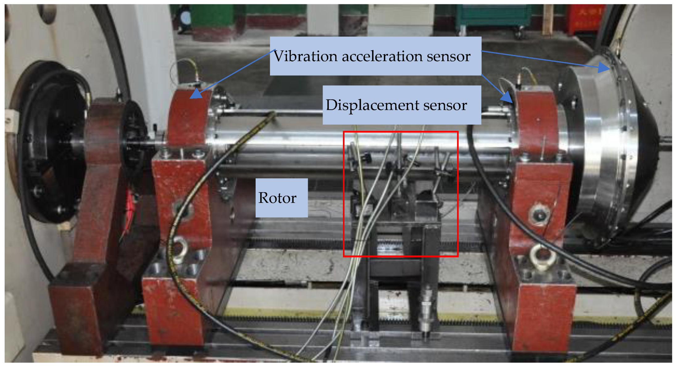
4.1. Equipment and Test Rig

The experiment was conducted on a horizontal high-speed rotary tester, which is shown in Figure 9. It mainly consisted of a power system, a speed-increasing system, a support system, a lubricating oil system, a vacuum system, a control system, and a testing system.
The test parameters during the experiment are shown in Table 9, and the physical photos are shown in Figure 7.

4.2. Experimental Results and Analysis
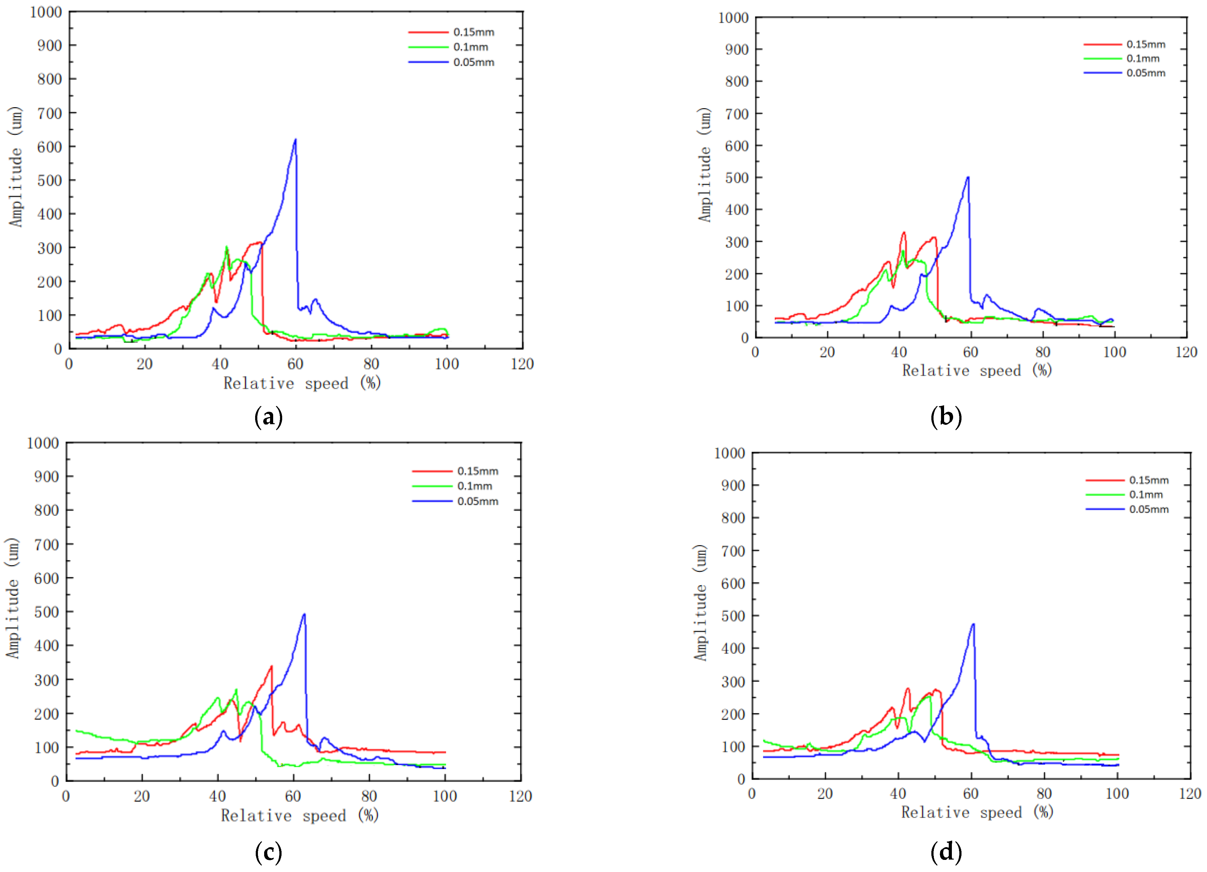
The amplitude, as measured by the D1–D4 displacement sensors, was obtained when the oil film radial clearances at Bearing 2 were 0.05 mm, 0.10 mm, and 0.15 mm, as shown in Figure 8.
In this section, the main conclusions are:
(1)
As the oil film clearance increases, the critical speed gets smaller, and the amplitude at the critical speed decreases, indicating that NCSFD has a good vibration reduction effect when the rotor reaches the critical speed. However, when the oil film clearance is greater than 0.10 mm, the reduction in amplitude tends to be less significant.
(2)
When the oil film clearance is 0.05 mm, the rotor response amplitude and corresponding critical speed are both large.
(3)
When the oil film clearance is 0.15 mm, the response amplitude of the rotor at high speed after crossing the critical point is larger.
(4)
When the oil film clearance is 0.10 mm, the response amplitude of the rotor is small at critical speed and supercritical speed, and the operating speed range is wider. Therefore, it is more reasonable to take 0.10 mm as the oil film clearance.
Additionally, based on the experimental results, the critical speed of the rotor was obtained. Based on the calculated critical speed value and the fact that the deflection of the rotor before 40% n is small and there is no obvious peak, it is judged that the first critical speed is not significant. The second critical speed was analyzed, and the experimental results were compared and analyzed with the calculated results, as shown in Table 10. In Table 10, the experimental values are the average values of each measurement point.
Within a certain range, as the oil film clearance increases, the calculation error of critical speed increases, but it is not greater than 7.62%. The calculation model reflects the dynamic characteristics of the rotor well.

5. Wide Speed Domain Stability Test of the Rotor System

Based on the optimized oil film radial clearances, stability tests were conducted on the NCSFD rotor system in the wide speed range of 0.51 n~1.0 n. Drive the rotor to different characteristic speeds, then stay at the speeds for 5 min, respectively, and then record the change value of rotor vibration amplitude and support vibration acceleration, as shown in Table 11 and Table 12, respectively. The variation curve of rotor vibration amplitude with speed measured by D1~D4 displacement sensors within the speed range of 0.51 n~1.0 n is shown in Figure 10. The variation curve of rotor vibration acceleration with speed measured by the A1~A6 accelerometer in the speed range of 0.51 n~1.0 n is shown in Figure 11.
The results revealed that the rotor system has a deflection variation of no more than 4 μm and a vibration acceleration variation of no more than 0.04 g within the wide operating speed range of 0.51 n~1.0 n, with very small vibration variation values. In addition, the vibration amplitude and acceleration of the rotor within the speed range of 0.51 n~1.0 n are relatively small, which can meet the requirements of long-term operation of the rotor.
Therefore, it can be considered that the rotor system operates stably within the wide operating speed range of 0.51 n~1.0 n.

6. Conclusions

This paper investigates the impact of varying oil film radial clearances on the dynamic characteristics of the NCSFD variable-speed rotor system. Additionally, it studied the stability of the variable-speed rotor across a wide range of operating speeds. Some conclusions are summarized as follows:
(1)
The equivalent rotor dynamic characteristics designed have good consistency with the actual rotor, verifying the practical efficacy of the proposed dynamic similarity design method.
(2)
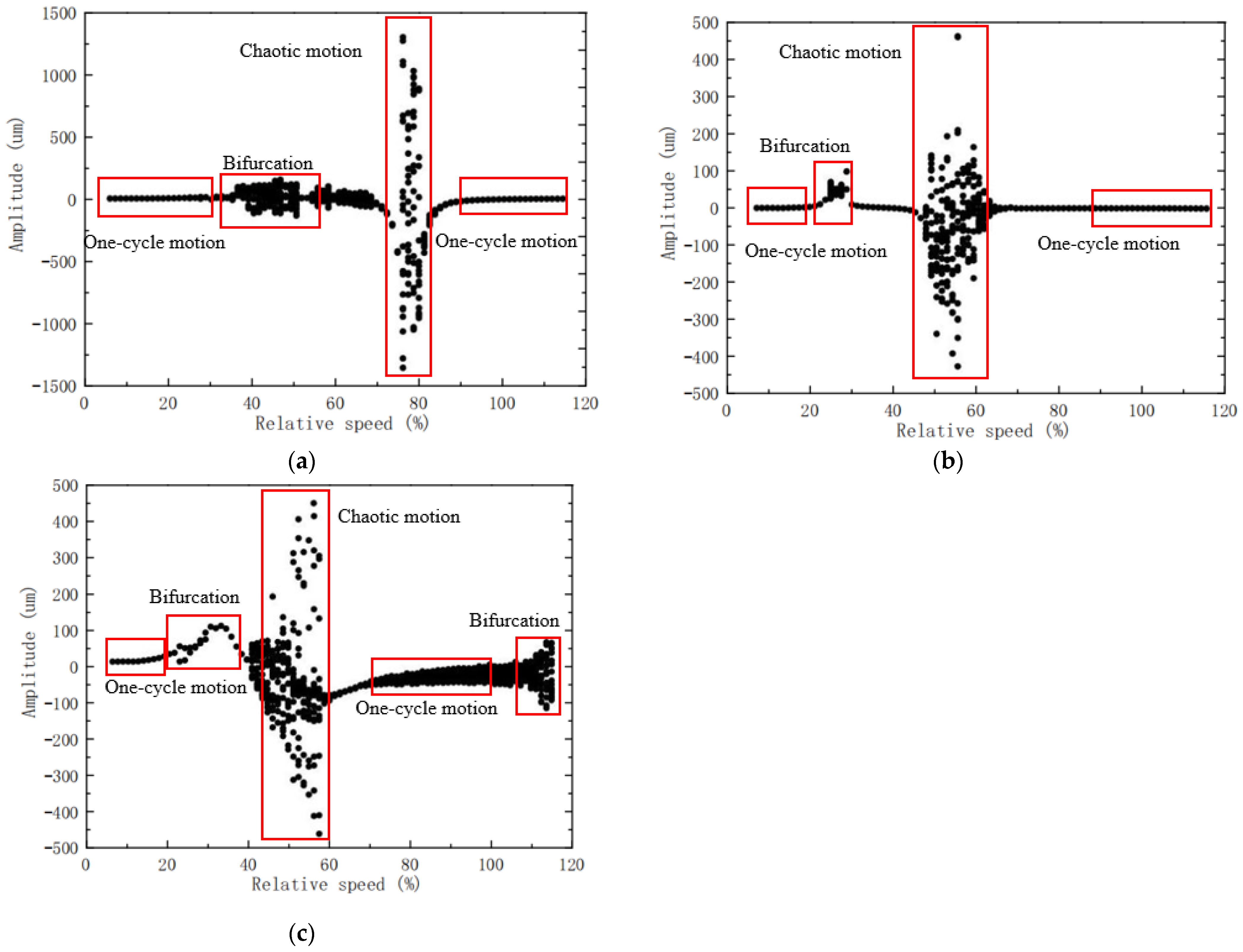
The rotor system with NCSFD exhibits obvious nonlinear characteristics, with the rotor exhibiting “single period motion” at low speeds, then gradually entering “chaotic motion” through bifurcation, and finally returning to “single period motion.” Different oil film radial clearances can lead to differences in the specific speed range of bifurcation points, “single period motion,” and “chaotic motion” regions.
(3)
Theoretical analysis and experimental verification have shown that selecting 0.10 mm as the oil film clearance is optimal. To expand the rotor’s operating speed range, increasing the oil film clearance is feasible, although attention should be paid to the rotor’s response amplitude at high speeds.
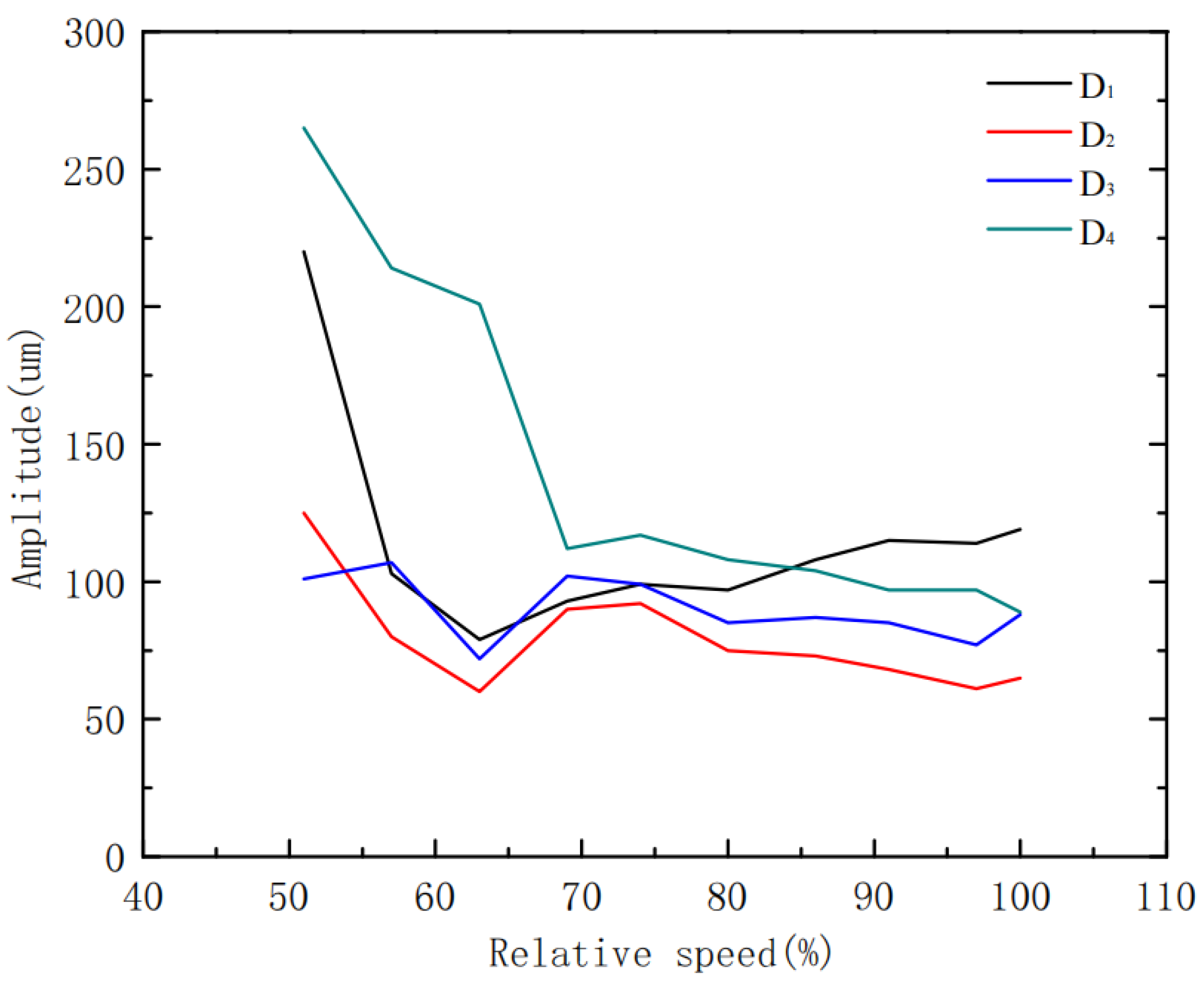
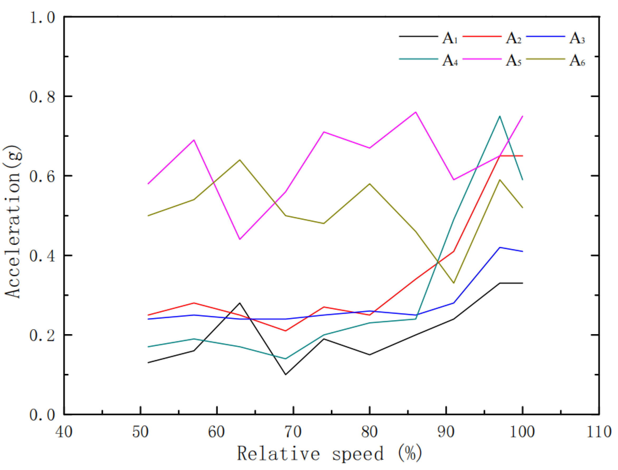
(4)
The rotor system has a deflection variation of no more than 4 μm and a vibration acceleration variation of no more than 0.04 g within the rotating speed range of 0.51 n to 1.0 n. This indicates that it has a wide working speed range.
This work mainly focuses on the parametric study of the effect of clearance on the rotor dynamics instead of the optimal study of the different designing parameters. The optimal design of the NCSFD parameters will be carried out in our future research. Additionally, the conclusions in this work only cover the NCSFDs, which cannot be extended to the concentric squeeze film dampers.

Author Contributions

Conceptualization, G.T.; Methodology, X.Y.; Formal analysis, W.N.; Investigation, X.Y.; Resources, G.T.; Data curation, G.W.; Writing—review & editing, W.N.; Supervision, Q.Z. All authors have read and agreed to the published version of the manuscript.

Funding

This research was funded by Technology Innovation Platform Fund Project of AECC: CXPT-2022-031.

Data Availability Statement

Data are contained within the article.

Conflicts of Interest

Author Guang Tang was employed by the company Aero Engine Corporation of China. The remaining authors declare that the research was conducted in the absence of any commercial or financial relationships that could be construed as a potential conflict of interest.

References

  1. Tai, X.Y.; Li, K.H. Rotor dynamics analysis of centrifugal compressor considering elastic foundation characteristics. CHN. J. Turbo. 2020, 62, 57–63. [Google Scholar]
  2. Jiang, L.J.; Yuan, J.B. Dynamic analysis of cantilever rotor considering impeller coupling. CHN. J. Turbo. 2020, 62, 16–21. [Google Scholar]
  3. Barra, F.; Capone, P.; Monstein, R. Implementation of a comprehensive mathematical model for tilt-rotor real time flight simulation. In Proceedings of the 45th European Rotorcraft Forum, Warsaw, Poland, 17–20 September 2019. [Google Scholar]
  4. Song, M.B.; Yan, P.; Wang, X.; Xiang, Y.Z.; Yang, Y.; Xie, R.H. Exploration of maximum unbalance of a turboshaft engine based on airworthiness requirements. J. Aerosp. Power 2023, 38, 1467–1473. [Google Scholar]
  5. Gerard, E.W. Overview of variable speed power turbine research. In Proceedings of the NASA Fundamental Aeronautics Conference, Cleveland, OH, USA, 15–17 March 2011. [Google Scholar]
  6. Hendricks, E.S.; Jones, S.M.; Gray, J.S. Design optimization of a variable speed power turbine. In Proceedings of the 50th AIAA/ASME/SAE/ASEE Joint Propulsion Conference, Cleveland, OH, USA, 28–30 July 2014. [Google Scholar]
  7. Zhang, G.H.; Huang, Y.Z.; Chen, Y.L.; Wang, Z.L.; Xu, K.F.; Feng, L. Experiment on vibration reduction performance of elastic ring squeeze film damper under sudden unbalance. J. Aerosp. Power 2023, 38, 32–40. [Google Scholar]
  8. Zhao, L.; Liao, M.F.; Wang, S.J.; Liu, Q.Y.; Hou, L.Z. Experimental study on vibration reducing effect of elastic ring squeeze film damper. J. Propuls. Technol. 2021, 42, 1129–1137. [Google Scholar]
  9. Zhang, L.H.; He, L.D.; Chen, Z.; Wan, F.T.; Ding, J.C. Structure design of an integral elastic ring squeeze film damper and experiments on the rotor passing through critical speed. J. Vib. Shock 2019, 38, 72–78, 108. [Google Scholar]
  10. Yang, X.M.; Jiang, B.Z.; Li, Y.; Zhao, Q.; Deng, S.E.; Zhang, W.H.; Cui, Y.C. Dynamic characteristics of elastic ring squeeze film damper coupled high-speed ball bearings. J. Sound Vib. 2022, 537, 117186. [Google Scholar] [CrossRef]
  11. Han, Z.F.; Ding, Q.; Wang, W. Dynamical analysis of an elastic ring squeeze film damper-rotor system. Mech. Mach. Theory 2019, 131, 406–419. [Google Scholar] [CrossRef]
  12. Gheller, E.; Chatterton, S.; Vania, A.; Pennacchi, P. Squeeze Film Damper Modeling: A Comprehensive Approach. Machines 2022, 10, 781. [Google Scholar] [CrossRef]
  13. Xu, Y.; Cao, H.R.; Shi, J.H.; Pei, S.Y.; Zhang, B.; She, K.L. A comprehensive multi-parameter optimization method of squeeze film damper-rotor system using hunter-prey optimization algorithm. Tribol. Int. 2024, 194, 109538. [Google Scholar] [CrossRef]
  14. Wang, H.; Zhao, Y.; Luo, Z.; Han, Q. Analysis on influences of squeeze film damper on vibrations of rotor system in aeroengine. Appl. Sci. 2022, 12, 615. [Google Scholar] [CrossRef]
  15. Luo, Z.; Sun, K.; Ge, X.D.; Zhou, G.Z.; Cui, Z.W. Dynamic analysis of the rotor system with elastic ring squeeze film damper considering oil film temperature. Nonlinear Dyn. 2023, 111, 15981–16002. [Google Scholar] [CrossRef]
  16. Chen, X.; Ren, G.M.; Gan, X.H. Dynamic behavior of a flexible rotor system with squeeze film damper considering oil-film inertia under base motions. Nonlinear Dyn. 2021, 106, 3117–3145. [Google Scholar] [CrossRef]
  17. Gunter, E.J. Steady State and Transient Analysis of a Squeeze Film Damper Bearing for Rotor Stability; National Technical Information Service: Charlottesville, VA, USA, 1975. [Google Scholar]
  18. Holmes, R.; Dogan, M. Investigation of a rotor bearing assembly incorporating a squeeze-film damper bearing. J. Mech. Eng. Sci. 1982, 24, 129–137. [Google Scholar] [CrossRef]
  19. Roberts, J.B.; Ellis, J.; Carraseo, A. An experimental study of the nonlinear behavior of a squeeze film bearing. J. Trib. 1993, 115, 312–318. [Google Scholar] [CrossRef]
  20. Holmes, R.; Box, S. Study on the use of squeeze film dampers in rotor support structures. Mach. Vibr. 1992, 1, 71–79. [Google Scholar]
  21. Holmes, R.; Sykes, J.E.H. The vibration of an aero-engine rotor incorporating two squeeze-film dampers. Proc. Inst. Mech. Eng. Part G J. Aerosp. Eng. 1996, 210, 39–51. [Google Scholar] [CrossRef]
  22. Sykes, J.E.H.; Holmes, R. The effect of bearing misalignment on the nonlinear vibration of aero-engine rotor damper assembles. Proc. Inst. Mech. Eng. Part G J. Aerosp. Eng. 1990, 204, 83–99. [Google Scholar] [CrossRef]
  23. Bai, J.; Pan, B.; He, W.B. Sudden unbalance response analysis of cantilever rotor system with squeeze film damper. Sci. Technol. Eng. 2018, 18, 299–305. [Google Scholar]
  24. Xia, N.; Meng, G. Non-synchronous response and bifurcation character of two-disk rotor system with a non-centralized SFD. J. Northw. Polytechn. Univ. 2000, 18, 216–220. [Google Scholar]
  25. Cui, Y.; Wang, Q.Z.; Wang, Y.L.; Li, T. Numerical simulation on cavitation flow filed characteristics of nonconcentric squeeze film damper. J. Harb. Eng. Univ. 2020, 41, 978–984. [Google Scholar]
  26. Chen, S.Q.; Wang, G.Y.; Jia, Z.B.; Xu, J.K. Steady-state unbalance response of a rigid rotor in squeeze film damper bearings without centralizing springs. J. Northw. Polytech. Univ. 1985, 3, 117–128. [Google Scholar]
  27. Andres, L.S.; Seshagiri, S. Damping and inertia coefficients for two end sealed squeeze film dampers with a central groove: Measurements and predictions. J. Eng. Gas Turb. Power 2013, 135, 112503-1-9. [Google Scholar]
  28. Andres, L.S. Force coefficients for a large clearance open end squeeze film damper with a central feed groove: Experiments and predictions. Tribol. Int. 2014, 71, 17–25. [Google Scholar] [CrossRef]
  29. Jawaid, I.I. Bifurcations of a flexible rotor response in squeeze-film dampers without centering springs. Chaos Solitons Fractals 2004, 24, 583–596. [Google Scholar]
  30. Zhu, C.S.; Mao, C.; Li, P.F. Experimental comparison of vibration isolation ability of centralized and uncentralized squeeze film damper. J. Aerosp. Power 2017, 32, 2672–2679. [Google Scholar]
  31. Feng, Y.; Deng, W.Q.; Liu, W.K.; Yuan, S.; Hu, T.X. Comparative experimental investigation on vibration attenuating characteristics of concentric and non-concentric squeeze film damper. Mech. Sci. Technol. Aerosp. Eng. 2023, 42, 978–984. [Google Scholar]
  32. Chauhan, S.; Singh, M.; Aggarwal, A.K. Bearing defect identification via evolutionary algorithm with adaptive wavelet mutation strategy. Measurement 2021, 179, 109445. [Google Scholar] [CrossRef]
  33. Chauhan, S.; Singh, M.; Kumar Aggarwal, A. An effective health indicator for bearing using corrected conditional entropy through diversity-driven multi-parent evolutionary algorithm. Struct. Health Monit. 2021, 20, 2525–2539. [Google Scholar] [CrossRef]
  34. Chauhan, S.; Singh, M.; Aggarwal, A.K. Cluster head selection in heterogeneous wireless sensor network using a new evolutionary algorithm. Wirel. Pers. Commun. 2021, 119, 585–616. [Google Scholar] [CrossRef]
  35. Yang, X.G.; Luo, G.H.; Tang, Z.H.; Wang, F. Modeling method and dynamic characteristics of high-dimensional counter-rotating dual rotor system. J. Aerosp. Power 2014, 29, 585–595. [Google Scholar]
  36. Chiang, H.W.D.; Hsu, C.N.; Tu, S.H. Rotor-bearing analysis for turbo machinery single and dual-rotor systems. J. Propuls. Power 2004, 20, 1096–1104. [Google Scholar] [CrossRef]
  37. Fu, C.G.; Zheng, T.P.; Ou, Y.X. Rotor Dynamics and Whole Engine Vibration (No.19 Volume of Aeroengine Design Manual), 3rd ed.; Aviation Industry Press: Beijing, China, 2000. [Google Scholar]
Figure 1. Schematic diagram of the simulated rotor structure.
Machines 12 00882 g001
Figure 2. Structure of NCSFD.
Machines 12 00882 g002
Figure 3. Schematic diagram of the true rotor structure.
Machines 12 00882 g003
Figure 4. Bifurcation diagram. (a) c = 0.05 mm; (b) c = 0.10 mm; (c) c = 0.15 mm.
Machines 12 00882 g004
Figure 5. Nonlinear response characteristics (c = 0.10 mm, 1.0 n). (a) Poincaré section; (b) Frequency spectrum.
Machines 12 00882 g005
Figure 6. Nonlinear response characteristics (c = 0.15 mm, 1.0 n). (a) Poincaré section; (b) Frequency spectrum.
Machines 12 00882 g006
Figure 7. The physical photo of the rotor on the test rig.
Machines 12 00882 g007
Figure 8. Amplitude changes with speed under different oil film radial clearances. (a) D1; (b) D2; (c) D3; (d) D4.
Machines 12 00882 g008
Figure 9. Composition of test equipment. Here, 1 represents a power system; 2 represents a speed-increasing system; 3 represents a support system; 4 represents a lubricating oil system; 5 represents a vacuum system; 6 represents a control system; 7 represents the testing system.
Machines 12 00882 g009
Figure 10. Variation curve of rotor vibration amplitude with speed measured by D1~D4 displacement sensors within the speed range of 0.51 n~1.0 n.
Machines 12 00882 g010
Figure 11. Variation curve of rotor vibration acceleration with speed measured by A1~A6 accelerometers within the speed range of 0.51 n~1.0 n.
Machines 12 00882 g011
Table 1. Main structural parameters of the rotor.
Structural ParametersValue
Length1400 mm
Shaft diameter50 mm
Mass35 kg
Table 2. Comparison of mass characteristics between real disks and equivalent disks.
DisksMass (kg)Axial Position of Mass Center (mm)Radius of Gyration (mm)
Equivalent disks29.554−69.392128.84
True disks29.995−67.128128.89
Error rate (%)1.493.370.03
Table 3. Stiffness of each support.
Bearing NumberSupport Stiffness (107 N∙m−1)
Bearing15.00
Bearing21.50
Bearing33.50
Bearing40.01
Table 4. Comparison results of the critical speeds.
Critical Speed OrderValue of True RotorValue of Equivalent RotorError (%)
First0.278 n0.264 n2.50
Second0.515 n0.517 n0.30
Third1.465 n1.488 n3.98
Table 5. Comparison results of the mode shapes.
Mode Shapes OrderTrue RotorEquivalent Rotor
FirstMachines 12 00882 i001Machines 12 00882 i002
SecondMachines 12 00882 i003Machines 12 00882 i004
ThirdMachines 12 00882 i005Machines 12 00882 i006
Table 6. Stiffness of support.
Oil Film Radial Clearance Value (mm)Support Stiffness (107 N∙m−1)
Bearing 1Bearing 2Bearing 3Bearing 4
0.055.002.593.500.01
0.105.000.323.500.01
0.155.000.103.500.01
Table 7. Calculation result and margin of critical speeds.
Oil Film Radial Clearance Value (mm)First Three Orders Critical Speed And Margins (%)
FirstSecondThird
0.050.283 n, 44.540.609 n, 5.801.859 n, 85.93
0.100.239 n, 22.060.443 n, 31.471.340 n, 33.95
0.150.220 n, 12.010.422 n, 34.731.305 n, 30.50
Table 8. Calculation results of vibration shapes.
Oil Film Radial Clearance Value (mm)First Three Orders Mode Shapes
FirstSecondThird
0.05Machines 12 00882 i007Machines 12 00882 i008Machines 12 00882 i009
0.10Machines 12 00882 i010Machines 12 00882 i011Machines 12 00882 i012
0.15Machines 12 00882 i013Machines 12 00882 i014Machines 12 00882 i015
Table 9. Test parameters.
ParametersSensorsUnit
AmplitudeDisplacement sensor (D1–D4)μm
Vibration accelerationVibration acceleration sensor (A1–A6)g
Table 10. Calculation error of critical speeds.
Oil film Radial Clearance Value (mm)Experimental ValueCalculated ValueError (%)
0.050.630 n0.609 n3.21
0.100.475 n0.443 n7.04
0.150.457 n0.422 n7.62
Table 11. Variation in rotor vibration amplitude.
Speeds0.51 n0.57 n0.63 n0.69 n0.74 n0.80 n0.86 n0.91 n0.97 n1.0 n
Variation value (μm)D1220~224103~10579~8193~9699~10297~99108~110115~117114~116119~121
D2125~12680~8260~6290~9292~9475~7773~7568~6961~6365~67
D3101~103107~10972~74102~10599~10285~8787~8985~8777~8088~90
D4265~268214~217201~203112~114117~120108~110104~10697~10097~9989~93
Table 12. Variation in vibration acceleration.
Speeds0.51 n0.57 n0.63 n0.69 n0.74 n0.80 n0.86 n0.91 n0.97 n1.0 n
Variation value (g)A10.13~0.160.16~0.180.28~0.300.10~0.130.19~0.220.15~0.180.20~0.230.24~0.260.33~0.350.33~0.35
A20.25~0.280.28~0.300.25~0.280.21~0.240.27~0.300.25~0.280.34~0.380.41~0.440.65~0.680.65~0.68
A30.24~0.260.25~0.280.24~0.280.24~0.270.25~0.270.26~0.280.25~0.280.28~0.300.42~0.450.41~0.44
A40.17~0.190.19~0.220.17~0.200.14~0.170.20~0.240.23~0.260.24~0.260.49~0.510.75~0.780.59~0.61
A50.58~0.620.69~0.720.44~0.470.56~0.600.71~0.740.67~0.710.76~0.800.59~0.620.65~0.680.75~0.77
A60.50~0.530.54~0.570.64~0.660.50~0.540.48~0.510.58~0.600.46~0.490.33~0.350.59~0.620.52~0.56
Disclaimer/Publisher’s Note: The statements, opinions and data contained in all publications are solely those of the individual author(s) and contributor(s) and not of MDPI and/or the editor(s). MDPI and/or the editor(s) disclaim responsibility for any injury to people or property resulting from any ideas, methods, instructions or products referred to in the content.

