Article

Research on the Entrance Damage of Carbon Fiber-Reinforced Polymer/Ti6Al4V Stacks in Six-Degrees-of-Freedom Robot Drilling

1
School of Mechanical and Power Engineering, Henan Polytechnic University, Jiaozuo 454003, China
2
School of Mechanical Engineering, Zhengzhou University of Aeronautics, Zhengzhou 450046, China
*
Author to whom correspondence should be addressed.
Machines 2024, 12(12), 881; https://doi.org/10.3390/machines12120881
Submission received: 8 November 2024 / Revised: 30 November 2024 / Accepted: 2 December 2024 / Published: 4 December 2024
(This article belongs to the Section Material Processing Technology)

Abstract

Carbon fiber-reinforced polymer (CFRP)/titanium alloy (Ti6Al4V) stacks are widely used in the aerospace industry due to their excellent physical properties. The substantial demand for drilling components in the aerospace industry necessitates the implementation of enhanced processing efficiency and drilling quality standards. Six-degrees-of-freedom robots are commonly used in the aerospace industry due to their high production efficiency, high flexibility, and low labor costs. However, due to the weak stiffness, chatter is prone to occur during processing, which has a detrimental impact on the quality of the finished product. As an advanced processing technology, ultrasonic-assisted machining technology can effectively reduce the cutting force and suppress the chatter in the drilling process, so it is widely used in production. In this paper, first, the robot kinematic (dexterity) and stiffness performance is analyzed. Then, the appropriate range of the machining plane and the posture of the robot in the workspace are selected. Finally, the vibration and CFRP entrance damage during the machining process are compared and studied in conventional robotic drilling (CRD) and ultrasonic-assisted robotic drilling (UARD). The experimental results demonstrate that the UARD is an effective method for reducing vibration during the machining process. Compared with the CRD, the CFRP entrance delamination damage in UARD is reduced. Under the appropriate processing parameters, the entrance delamination factor could be reduced by 15%, and the burr height could be reduced by 45%. Obviously, the UARD is a promising process to improve the CFRP entrance delamination damage.

1. Introduction

CFRP exhibits a number of advantageous properties, including a lightweight nature, high tensile strength, and good heat resistance. It is manufactured and used in the aircraft industry as connectors. However, although it is widely used in the aerospace industry, it is also limited by its performance, such as its low interlayer strength and moisture absorption. Therefore, the stack components of CFRP and metal materials naturally emerge as the times require and become the emerging materials in the aerospace field. The CFRP/Ti alloy stack structure material not only ensures the lightweight and high-strength properties of the material itself but also effectively avoids the shortcomings of low strength between CFRP layers. Special machine tools are generally used for drilling large composite parts such as aircraft fuselages and wings. However, with the development of time, their high processing cost and poor manufacturing flexibility limit the processing efficiency of aircraft production.
The development of robotic automatic drilling technology, characterized by high production efficiency, flexibility, and low labor cost, has led to its widespread adoption in modern aircraft manufacturing. This technology significantly enhances production efficiency and accelerates the industry’s growth [1,2,3]. However, industrial robots face limitations due to their weak stiffness, particularly when processing high-strength materials, which can result in chatter and adversely affect material quality [4,5]. The stiffness performance of the robot is influenced by its posture, as noted by Liao et al. [6], who observed that changes in a robot’s high stiffness posture exhibit regional characteristics. Consequently, large surfaces are divided into sub-regions for analysis. Slamani et al. [7] investigated the impact of robot posture on high-speed trimming of CFRP materials, finding that posture significantly affects trimming performance. To assess robot stiffness, Salisbury [8] introduced a conventional stiffness model, which is widely used. Building on this, Abele et al. [9] developed a flexibility model that circumvents the need for calculating the inverse matrix of the Jacobian. Various evaluation indices have since been proposed to calculate and optimize stiffness performance in space. For instance, Chen et al. [10] introduced the NSPI to evaluate robot stiffness under specific postures. This NSPI optimization objective aids in determining the optimal machining posture and feed direction for robot milling. Celikag et al. [11] put forth a methodology for enhancing the stiffness performance of a robot milling apparatus through the utilization of functional redundant degrees of freedom inherent to the tool axis, thereby preventing the occurrence of chatter. Bu et al. [12] introduced a Cartesian flexibility model to describe robot stiffness at Cartesian points, defining a quantitative evaluation index for machining performance. This model ensures optimal drilling posture, enhancing drilling depth and axial accuracy. Guo et al. [13] developed a performance index for evaluating robot stiffness in a given pose and established a pose optimization model aimed at maximizing stiffness performance to improve machining efficiency and quality. Liao. [14] proposed a method for simultaneously optimizing robot pose stiffness and workpiece setting to enhance overall stiffness during the milling of free-form workpieces. Lu et al. [15] addressed the inverse kinematics problem by optimizing joint motion through redundant angles, enabling smooth, collision-free motion along a given tool path. Julian et al. [16] introduced a method and structure for automatically calculating rigid motion in industrial robots, resolving motion redundancy optimization in milling and significantly improving machining accuracy. Dumas et al. [17] highlighted that eliminating redundant angles in the milling process minimizes total deformation along the cutting path. Tunc, L.T. et al. [18] conducted a measurement of the frequency response under quasi-static conditions that differed from those measured under static conditions through robot milling experiments. This approach yielded more reliable and accurate results in robot stability analysis. Kratena, T. et al. [19] devised an add-on processor for a milling robot that generates real-time coordinates of robot joints for machining simulations, which can be employed for collision avoidance. Tepper, C. et al. [20] put forth a compliance model for robots that effectively reduces the amount of experimentation required to identify stiffness parameters and accurately predicts TCP deviations through robot milling experiments. The theoretical models employed in these studies effectively predict robot stiffness performance in consistent postures, providing a crucial foundation for analyzing optimal pose parameters in specific drilling areas, assuming constant machining force throughout the process.
Robots, due to their weak stiffness, often experience significant chatter during drilling operations. While most research on mitigating machining vibrations focuses on CNC machine tools, these findings are not directly applicable to robotic systems. However, advancements in end-effector mechanisms and corresponding processing methods have contributed to a more stable robotic machining process. The advent of compound energy field processing, laser-assisted processing, and ultrasonic-assisted processing has precipitated a rapid evolution in the domain of hole-making. In the processing of CFRP/metal stacked materials, laser processing is distinguished by its ability to achieve a high level of cleanliness, efficiency, stability, and reliability. However, this process is constrained by its high energy density, which can result in the formation of slag during processing and in environments with high processing temperatures [21]. To address these limitations, laser processing is often combined with robotic technology. In recent years, ultrasound-assisted machining has become a valuable tool in a multitude of fields. The miniaturized and straightforward ultrasonic vibration system allows for seamless integration into the corresponding tools and equipment, enabling participation in the actual processing of production. Coupled with technological advancements, the application costs of the ultrasonic machining system can be effectively applied to the actual product line, offering a cost-effective solution. The introduction of lightweight ultrasonic-assisted machining systems has gained traction in the robotic processing industry. Ultrasonic-assisted drilling compared to conventional machining methods offers several advantages, including reduced cutting force, smaller chip size, enhanced hole quality [22], and a more stable machining process. Onawumi et al. [23] demonstrated that the axial ultrasonic vibration drilling of CFRP/Ti significantly improved hole quality, reducing burr height by approximately 50% when examining the impact of feed rate on hole quality in CFRP/titanium alloy stacks ultrasonic drilling. Similarly, Wang C.H. et al. [24] conducted drilling experiments on CFRP/titanium alloy stacks materials using various methods. Their findings revealed that longitudinal–torsional ultrasonic vibration-assisted drilling resulted in less damage at the CFRP entrance, Ti exit, and interface, improved the morphology of the CFRP hole wall, reduced surface roughness, and minimized outlet burrs. Ma G et al. [25] conducted longitudinal torsional ultrasonic vibration drilling of CFRP and showed that longitudinal torsional ultrasonic vibration drilling can effectively suppress the defects caused by CFRP and improve the quality of the hole wall. Dong S. [26] demonstrated that ultrasonic-assisted drilling reduces the lateral chatter of robot drilling.
Ultrasonic-assisted machining can effectively reduce the force in the machining process, thereby reducing the vibration in the machining process and improving machining quality. Therefore, this paper combines ultrasonic-assisted drilling with robot drilling. Based on the optimal dexterity and stiffness performance posture of the robot in the workspace, the influence of different postures and drilling parameters on the damage of CFRP entrance is analyzed through experiments. The vibration displacement, CFRP entrance delamination factor, and burr height in the drilling process are studied and the appropriate posture and drilling parameters are planned.

2. Robot Kinematics Analysis

2.1. Robot Kinematics Model Based on the Modified D-H Method

The kinematics model is the basis for studying the kinematics performance of the robot and for establishing the stiffness model of the robot. The robotic drilling system used in this paper is based on the ABB IRB-6700 robot. The six joints of the robot are rotational joints. The position data between the joints of each robot are calculated, and the corresponding link model is established according to the modified D-H method, as shown in Figure 1, and the modified D-H parameters are shown in Table 1.

2.2. Kinematics Performance Analyzing

The degree of deformation of the robot’s transmission is defined as dexterity. During the movement of the robot, the limitation of the rotation angle of each joint inevitably results in a singular posture, which, in turn, gives rise to an ill-conditioned distribution of the Jacobian matrix and a reduction in the accuracy of the inverse matrix. This, in turn, affects the control of the robot. As the robot deviates from the singular posture, its kinematic performance and force transmission improve.
The condition number is one of the important indicators to measure the dexterity of robots, especially in evaluating the flexibility and operability of robots. The value of the condition number reflects the sensitivity and stability of the robot end-effector in performing tasks. Specifically, the smaller the number of conditions, the better the kinematic performance of the robot, and the robot is more stable and sensitive in performing tasks; on the contrary, the larger the number of conditions, the worse the kinematic performance of the robot, and the worse instability and error that may be encountered in performing tasks.
Defining the condition number of the Jacobian matrix [27] as the criterion for determining the optimal scale:
K J = J J 1 J J ± 1 ,
where represents the norm of the matrix, and the Euclidean norm is usually chosen. Based on the concept of the Forbenius norm of a matrix, Angeles defined the condition number of an m × n matrix M as follows:
K F M = 1 m t r M T M t r M T M 1 .
The condition number KF can be calculated by substituting the robot’s Jacobian matrix.
K F J = 1 m t r J T J t r J T J 1
K c = 1 K F J
A detailed examination of Formulae (3) and (4) reveals a clear correlation between the performance index Kc and the Jacobian matrix of the robot. In contrast to the condition number KF, the dexterity Kc provides a more intuitive representation of the robot’s flexibility. Specifically, a value of Kc closer to 1 indicates superior dexterity. By employing the modified D-H parameter model, it is possible to compute the Jacobian matrix corresponding to the robot’s posture and subsequently determine the value of Kc, once the six joint angles of the robot have been established.

3. Robot Stiffness Performance Analysis

The stiffness performance of the robot is primarily contingent upon the following factors: (1) the material and structure of the robot; (2) the transmission components and the end-effector; (3) the combination configuration and the posture. The first two items of the specified robot type have been determined, and the corresponding parameters of the third item should be adjusted according to the actual situation.
For industrial robots, the stiffness of the link rod is much greater than that of the joint. Therefore, it can be considered that the robot link rod is a rigid body, and only the final deformation caused by the flexibility of the joint is taken into account. The following assumptions are made: (1) the end-effector of the robot is a rigid body, and all deformations are caused by the weak stiffness of the robot; (2) the assumption of robot joint flexibility; i.e., all displacements are caused by elastic deformation; (3) the robot quasi-static assumption; i.e., when the robot processing conditions are stable, a small deformation will not cause the robot processing posture to change; it will remain stable in the process of processing.

3.1. Robot Static Stiffness Model

For a six-degrees-of-freedom robot, the following transformation can be used to study the stiffness mapping relationship between the joint space and the Cartesian space [28]. In this paper, the structure of the end-effector is simple, including only the feed system and the spindle; then, the following applies:
K = J T K q J 1 .
The aforementioned formula is referred to as the traditional static stiffness model. The configuration of the robot has a significant impact on its stiffness, including both its overall stiffness and its axial stiffness. Additionally, the Jacobian matrix undergoes changes in accordance with alterations in the robot’s configuration. Kq represents the joint stiffness matrix of the robot:
K q = d i a g K q 1 , K q 2 , K q 3 , K q 4 , K q 5 , K q 6 ,
where Kqi is the stiffness of the i-th joint of the robot. According to the company’s technical data,
K q = 9.6 × 10 6 , 6.3 × 10 6 , 7.5 × 10 6 , 9.5 × 10 5 , 2.3 × 10 5 , 1.3 × 10 5 .
Based on the relationship between force and deformation at the end of the robot,
F = K X = J T K q J 1 X ,
where F is the generalized force on the end of the robot, and X is the deformation of the end of the robot after the force is applied.

3.2. Robot Stiffness Performance Index

Because the dimensions of each factor in the stiffness matrix are not completely consistent, it is difficult to solve the stiffness. Therefore, K is subdivided into four constituent parts:
f m = K 1 K 2 K 3 K 4 d δ ,
where d is the translational deformation of the robot end, and δ is the rotational deformation of the robot end. K1 is the force–translation stiffness matrix, K2 is the force–rotation stiffness matrix, K3 is the torque–translation stiffness matrix, and K4 is the torque–rotation stiffness matrix, and all of these matrixes are 3 × 3 matrices. f is the robot end force vector, and m is the robot end torque vector. In actual machining, the main factor influencing the machining quality of the robot is the translational displacement of the tool [29]. The rotation generated by the torque at the end of the robot is very small and can be ignored; then, there is a relationship between f and d:
d = K 1 f .
The force is applied to the end of the robot. It is assumed that the unit force f deforming the end of the robot can be obtained as follows:
f 2 = f T f = d T K 1 K 1 T d = 1 .
As illustrated in Figure 2, the unit force set has the capacity to form an ellipsoid within a three-dimensional space, which is referred to as the stiffness ellipsoid. The eigenvectors of K1 are the directions of the ellipsoidal semi-axis and are orthogonal to each other. The three eigenvalues—λ1, λ2, and λ3—are the lengths of the three semi-axes of the ellipsoid, and their values reflect the ability of the robot end to resist the external force deformation in three directions. Among them, λ3 is the shortest semi-axis length, and the robot has the lowest stiffness in this direction. In light of the impact of the flexibility of the robot in the specified posture on the overall stiffness, it can be assumed that the overall stiffness is inextricably linked to the volume of the stiffness ellipsoid.
V = 4 3 π λ 1 λ 2 λ 3 = 4 3 π det K 1 K 1 T
Therefore, the all-around stiffness index Ka can be defined as follows:
K a = det K 1 K 1 T 6 .
In Figure 2, the yellow elliptical plane represents the mapping of the machining plane in the ellipsoid. λt1 and λt2 represent the semi-major axis and semi-major axis of the mapping surface, respectively. λd is the semi-axial normal vector of the drilling machining direction, which represents the stiffness performance index of the feed direction during the drilling process. Based on the requirements of the stiffness unit, the Kz of the machining direction may be selected as K z = λ d [30].
We proceed on the assumption that the vector λd (ex, ey, ez), the unit vector in the ellipsoid coordinate system, can be described as follows:
x e x = y e y = z e z = t .
The coordinate system of the stiffness ellipsoid with λ1, λ2, and λ3 as the lengths of the semi-axes can be described as follows:
x 2 λ 1 2 + y 2 λ 2 2 + z 2 λ 3 2 = 1 .
By combining the above two formulae, λd and Kz can be calculated, and the axial stiffness indices in the remaining two directions may also be analyzed using this methodology.
λ d = 1 e x 2 λ 1 2 + e y 2 λ 2 2 + e z 2 λ 3 2
K z = 1 e x 2 λ 1 2 + e y 2 λ 2 2 + e z 2 λ 3 2 4

4. Optimization Analysis of Drilling Posture

The selection of posture involves determining both the position of the robot’s end-effector within the workspace and the magnitude of its redundant angle. To optimize this selection, the dexterity of the robot is first assessed to evaluate its kinematics performance within the working space. Subsequently, the position and range of a suitable machining plane are identified. Following this, the stiffness distribution across the machining plane is calculated to ensure stability and precision. Finally, based on these analyses, the most appropriate drilling position for the robot is determined.

4.1. Kinematics Performance Optimization

Based on the dexterity analysis of part 2, taking Kc as the calculation index, since the joint angles ja1 and ja6 have no effect on the kinematics performance, ja1 = ja6 = 0 is chosen to simplify the calculation. Since the position of the end of the workspace is only related to the first three joint angles, and the last three joint angles mainly affect the posture of the end-effector, the influence of ja2 and ja3 and ja4 and ja5 on Kc is calculated.
The angle of non-singular values of ja4 and ja5 is selected, ja2 and ja3 are randomly assigned in the rotation range, and the influence on Kc is calculated as shown in Figure 3a. As illustrated in the figure, the range of influence of ja2 and ja3 on Kc is observed to be within the interval [0, 0.6]. When ja2∈[−40, 65] and ja3∈[30, 50], the robot has better kinematics dexterity; that is, when setting the position of the workbench, it should be placed in front of the robot and the position should not be too far. After calculating the range of values for ja2 and ja3, the robot’s range of motion in space is simulated, as shown in Figure 4. The range of Kc ≥ 0.5 can be selected to obtain the range in the X direction [1500, 2000], and the range in the Z direction is [800, 2215].
Similarly, the angle of ja2 and ja3 not close to the singular value is selected, and the influence of ja4 and ja5 on the end kinematics is calculated, as depicted in Figure 3b. Based on the selection of the area with Kc ≥ 0.5 and better motion performance, the value range of Kc in the better distribution area is [0.4, 0.6], and the influence of ja4 and ja5 on the kinematics performance index is smaller than that of ja2 and ja3, and the influence of ja5 on the index is significantly larger than that of ja4. When ja5∈[−100, −50] ∪ [50, 100], the robot exhibits better kinematics performance.

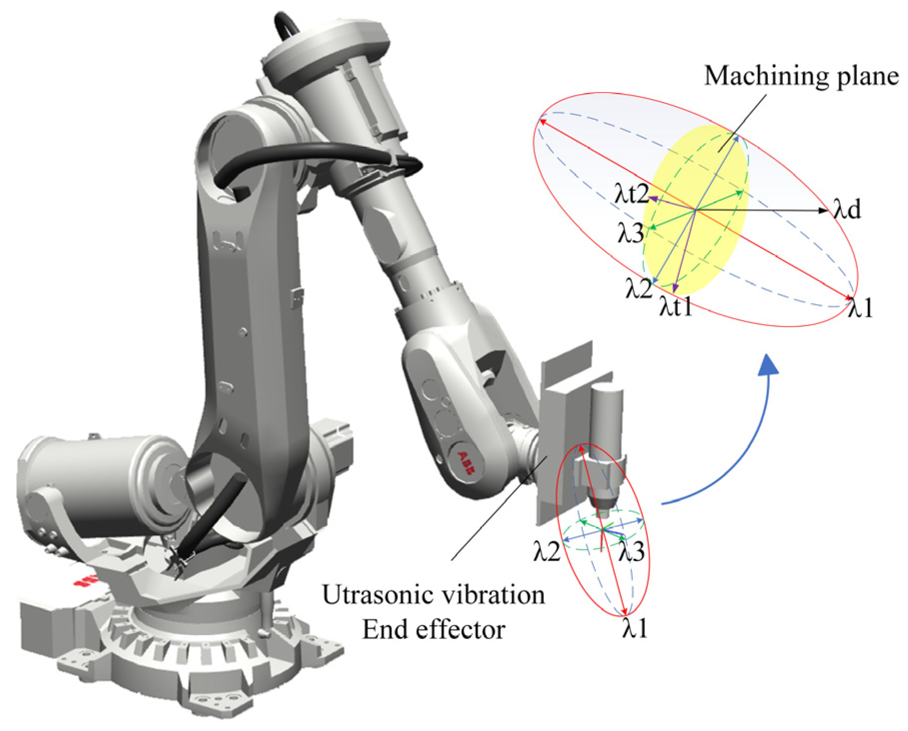
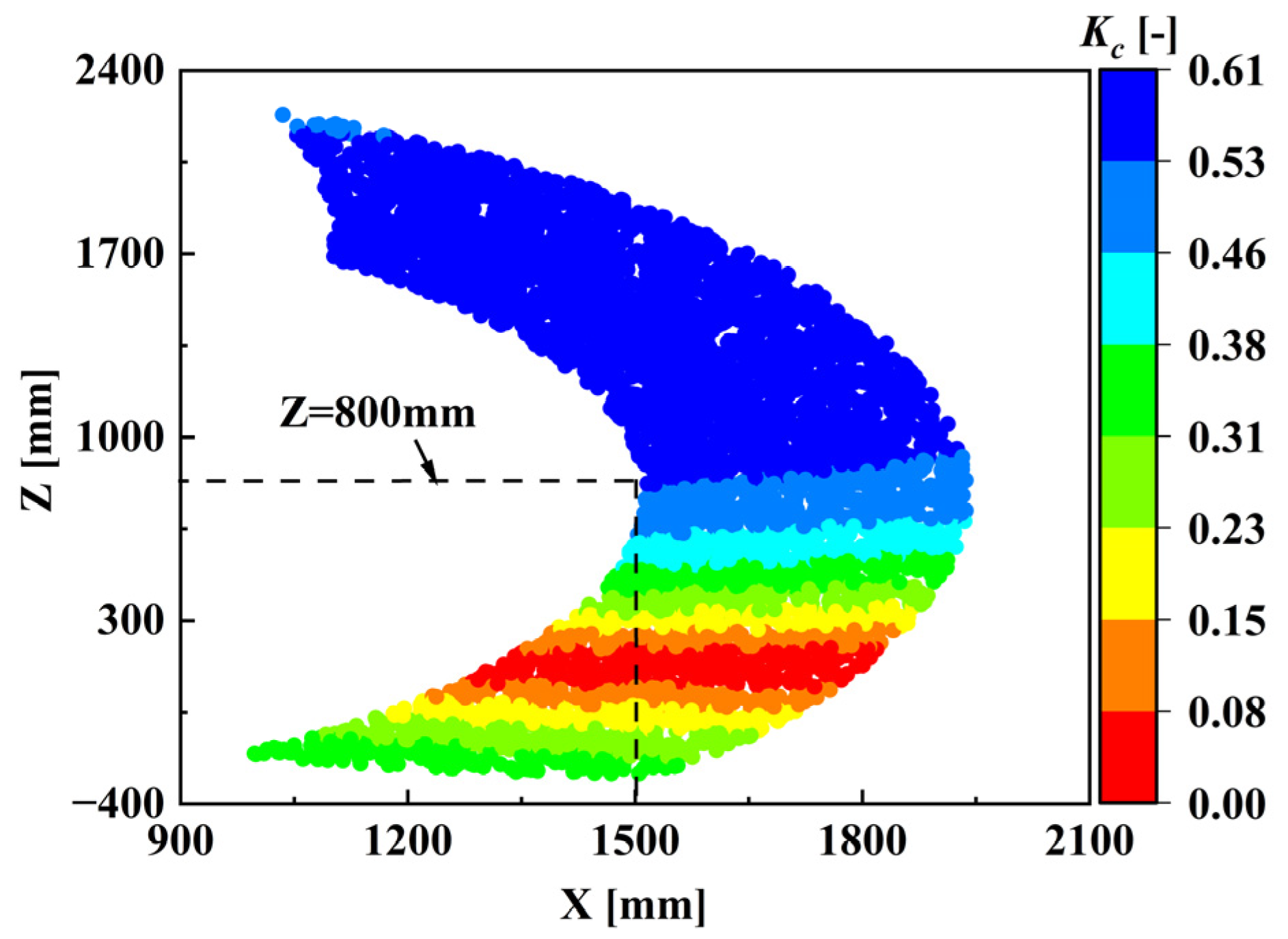
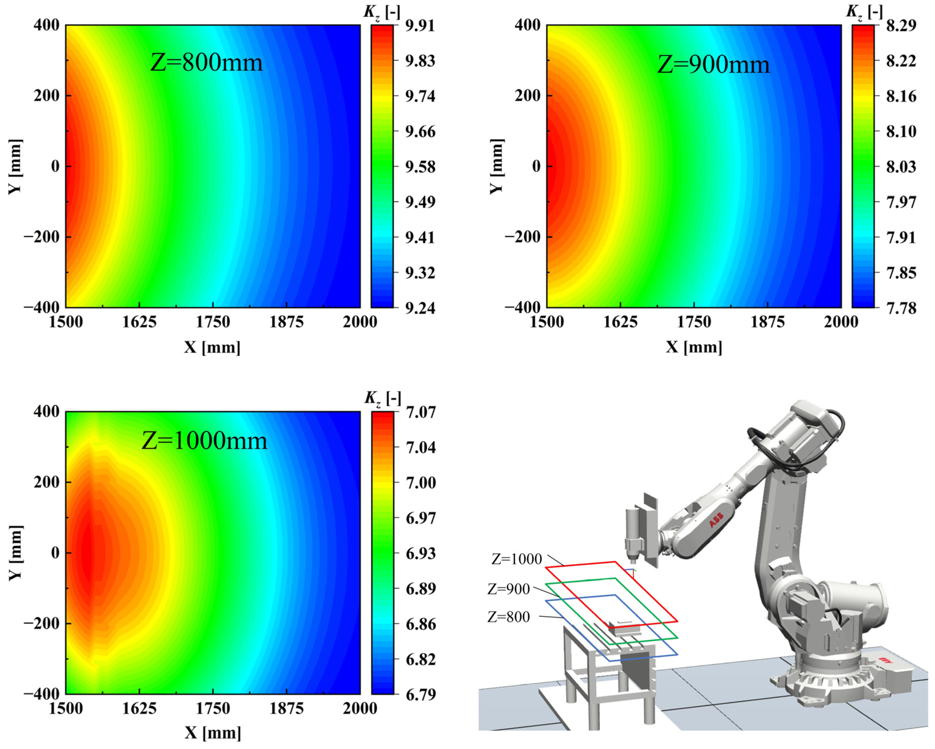
4.2. Optimization Analysis of Machining Plane Stiffness

After calculating and analyzing the appropriate rotation range of each joint, it can be seen from Figure 4 that the Z-direction height in the coordinate system that satisfies the kinematics performance requirements is over 800 mm, and the heights are selected sequentially as 800, 900, and 1000 mm. The stiffness index of the machining plane is calculated as shown in Figure 5. It can be seen that the stiffness distribution is better at X = 1500 mm, Y = 0 mm, and Z = 800 mm, which is more suitable for drilling.

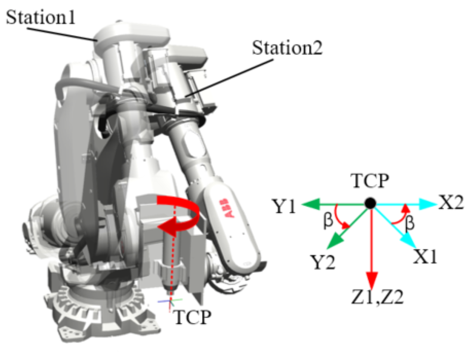
4.3. Robot End-Effector Redundancy Optimization

Once the machining position is determined, the robot can rotate around the tool axis while maintaining the axial direction of the tool and the position of the tool center point (TCP). This necessitates a comparison of the end stiffness across various redundant orientations. By analyzing the end-effector structure, an optimal redundant angle can be selected to enhance the machining stiffness of the robot, ensuring that there is no interference with the robot body during rotation. As each ∆β is applied, the robot posture will adjust according to the rotation angle, resulting in a new posture, as described in the Formula (19).
R o t z , Δ β = 1 0 0 0 0 cos ( Δ β ) sin ( Δ β ) 0 0 sin ( Δ β ) cos ( Δ β ) 0 0 0 0 1 ,
T e r = T e · R o t z , Δ β ,
where Ter is the posture transformation matrix of the robot after the rotation of ∆β, and Te is the posture transformation matrix of the robot before the rotation. The selection of the redundancy angle is analyzed in accordance with the value of the machining direction stiffness measure Kz, which is also considerable, indicating superior stiffness performance. The solution is determined by the robot’s machining attitude. In practice, the values of Te and Ter can be calculated based on the rotation angle of each axis joint and the corresponding end redundancy angle. Subsequently, the corresponding Jacobian matrix J can be solved, and then the Kz of the location can be calculated in accordance with the aforementioned content. Due to the structure of the end-effector, the redundancy range [0, 90°] is selected for calculation and ∆β = 1°. As the redundancy angle ∆β gradually increases, the end stiffness changes undergoes a corresponding change, as illustrated in Figure 6. It can be observed in Figure 7 that the stiffness index attains its maximum value at a redundancy angle of β = 78°.

5. Experimental Conditions and Schemes

5.1. Experimental System

The experimental platform and facilities are shown in Figure 8. The ABB IRB-6700 industrial robot is employed as the work carrier, manufactured by ABB, Zurich, Switzerland, load capacity is 200 Kg, and the drilling end-effector is bolted to the end flange. The force transducer and the vibration displacement sensor are placed on the workbench and the end-effector of the robot, respectively. The vibration displacement sensor is employed for the purpose of detecting the radial vibration displacement of the tool during the machining process, its type is WTVB01-485, cut-off frequency 1–100 Hz, made by China Witte Intelligence Company, Shenzhen, China. The entrance damage defects (delamination, burr, etc.) of processed holes were observed by the KEYENCE-VHX-2000 ultradepth of field three-dimensional microscope manufactured by Japan Keyence Corporation, Osaka, Japan, whose magnification is 100~1000×.

5.2. Tool and Workpiece

The experiment utilized a solid carbide tool (DG-ATD03-D4.00, Shanghai Tool Works Co., Ltd., Shanghai, China) featuring a TiAlN coating on its surface and a tip angle of 140°, as depicted in Figure 9a. The material used in the experiment, as illustrated in Figure 9b, is a unidirectional fiber-laying T700-12K CFRP composite stack, oriented in the 0°/180° fiber direction, with Ti6Al4V. This composite material has dimensions of 100 mm by 40 mm and a thickness of 5 mm. The detailed properties of the tool and material are provided in Table 2 and Table 3, respectively.

5.3. Experimental Method

In the design of processing parameters for the stacks machining of CFRP and Ti alloy, it is of paramount importance to take into account the considerable performance disparities between these two materials. Based on the research experiences of other scholars, it is determined that CFRP is optimally processed at higher speeds and lower feed rates, while Ti alloy demands lower speeds and higher feed rates [31]. As a result, the selection of appropriate processing parameters is indispensable to guarantee the quality of the hole and minimize the chatter. The spindle speed range utilized in this study is 1000–1600 r/min, and the feed rate is 10–40 mm/min. A single-factor experiment was carried out to compare and analyze the effects of machining process vibration, entrance burr height, and delamination factor in both CRD and UARD under varying machining parameters. Given CFRP’s susceptibility to cooling cutting fluids, the entire experiment was conducted under dry processing conditions to preclude any potential influence on material properties. To ensure consistency, the same type of new tools was employed for each processing method. To ensure the accuracy and precision of the results, each experiment was conducted three times, and the mean value was recorded as the final outcome. The specific details of the experimental parameters are presented in Table 4.

6. Results and Discussion

6.1. Theoretical Verification and Analysis

In the previous article, the dexterity performance and stiffness performance of the robot in the working space are analyzed, and the more suitable machining space is calculated. Here, the robot drilling experiment is verified based on the stiffness change trend of different machining planes and different redundant postures.
When the drilling sequence is from Ti alloy to CFRP, the high temperature generated in the Ti alloy drilling stage would cause severe thermal damage to the CFRP, especially in the Ti6Al4V/CFRP stack interface region. Worse, due to the lack of support at the CFRP exit, severe push-out delamination and fiber pull-out at the exit is very likely to occur; for this reason, this drilling order is used much less. So, the machining sequence is from CFRP to Ti alloy.
A spindle speed of 1400 r/min and a feed rate of 10 mm/min were selected for the purpose of verifying the machining of holes with plane heights of 800, 900, and 1000 mm, as shown in Figure 10. The vibration signal during the machining process was collected, and the average value was calculated as shown in Figure 11. The trend of the vibration signal is increasing. This is in accordance with the previous theoretical calculation of stiffness performance trends. Therefore, the initial machining position is set to (1500 mm, 0 mm, 800 mm).
After determining the height of the machining plane, the end-effector redundancy is optimized and analyzed. The interval angle is 10° from 0°, and four redundant positions are selected in turn to verify the changing trend. The drilling experiments were conducted in accordance with the prescribed machining parameters, specifically a spindle speed of 1400 r/min and a feed rate of 10 mm/min. The average vibration trend during the drilling process is illustrated in Figure 12. It can be demonstrated through intuitive observation that the average vibration displacement decreases as the value of β increases. Subsequently, an optimal redundancy angle of β = 78° is identified.

6.2. Vibration in Drilling Process

During the machining procedure, the vibration displacement sensor is employed to gather the vibration signal during the drilling process. After undergoing filtering and statistical processing, the average vibration displacement throughout the machining process can be attained. The processing parameters are set at 1000 r/min and 10 mm/min. The comparative analysis of diverse processing methods at each stage is presented in Figure 13. In accordance with the processing parameters established by the experiment, the robot drilling experiment is conducted, and the corresponding vibration displacement is calculated as depicted in Figure 14.
As illustrated in Figure 14, the vibration of UARD is predominantly diminished during the drilling process in comparison to CRD. A notable change in vibration is observed when the spindle speed is set to 1200 r/min. At a feed rate of 40 mm/min, UARD in the Ti alloy machining stage reduces the vibration size by about 52% in Figure 14b, which greatly reduces the vibration during machining. The reduction of vibration in the drilling process of CFRP/Ti alloy may be attributed to the alteration in chip shape of Ti alloy in the drilling stage, which is facilitated by the use of ultrasonic vibration. In comparison to CRD, the Ti alloy exhibits a transformation from a long-segment chip to a relatively short-segment chip, which serves to effectively suppress chatter during the machining process and enhance the quality of the hole. In general, the vibration in the drilling process is reduced and the machining process is more stable when using this method compared to conventional drilling.

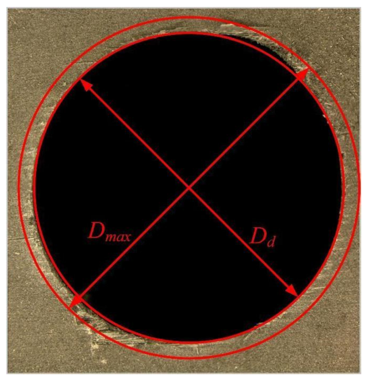
6.3. CFRP Entrance Delamination

In the drilling process of CFRP/Ti alloy stack materials, owing to its distinctive drilling procedure, the primary sources of damage at the entrance of CFRP are the peeling induced by the cutting force and additional scratches during the removal of Ti alloy chips. The principal effects of chip damage on the entrance are burrs, fiber pullout, and fiber tearing around the hole. Figure 15 shows the delamination damage at the entrance of CFRP under two machining methods with different feed rates (Vf) at a spindle speed of 1200 r/min. It is evident that the damage caused to the entrance of the CFRP by UARD is less severe than that caused by CRD.
Based on the one-dimensional evaluation criteria, the entrance delamination factor Fd is evaluated and calculated:
F d = D max D d
where Dmax is the diameter of the maximum delamination damage area, and Dd is the nominal diameter of the hole, as shown in Figure 16.
In accordance with the established experimental parameters, the drilling experiment was conducted, and the delamination factor at the entrance of CFRP under different drilling parameters was calculated, as shown in Figure 17.
From Figure 17, an increase in spindle speed and feed rate is accompanied by a corresponding rise in the entrance delamination factor. In Figure 17b, the entrance delamination factor of UARD is smaller than that of CRD, which confirms that UARD can effectively reduce the machining damage. At a spindle speed of 1200 r/min and a feed rate of 10 mm/min, the entrance delamination factor of UARD is about 15% smaller than that of CRD, and the entrance delamination factor after ultrasonic machining is a better value. In Figure 17c, when the spindle speed is 1400 r/min and feed rate is 30 mm/min, the delamination factor of UARD is the smallest, 1.09.

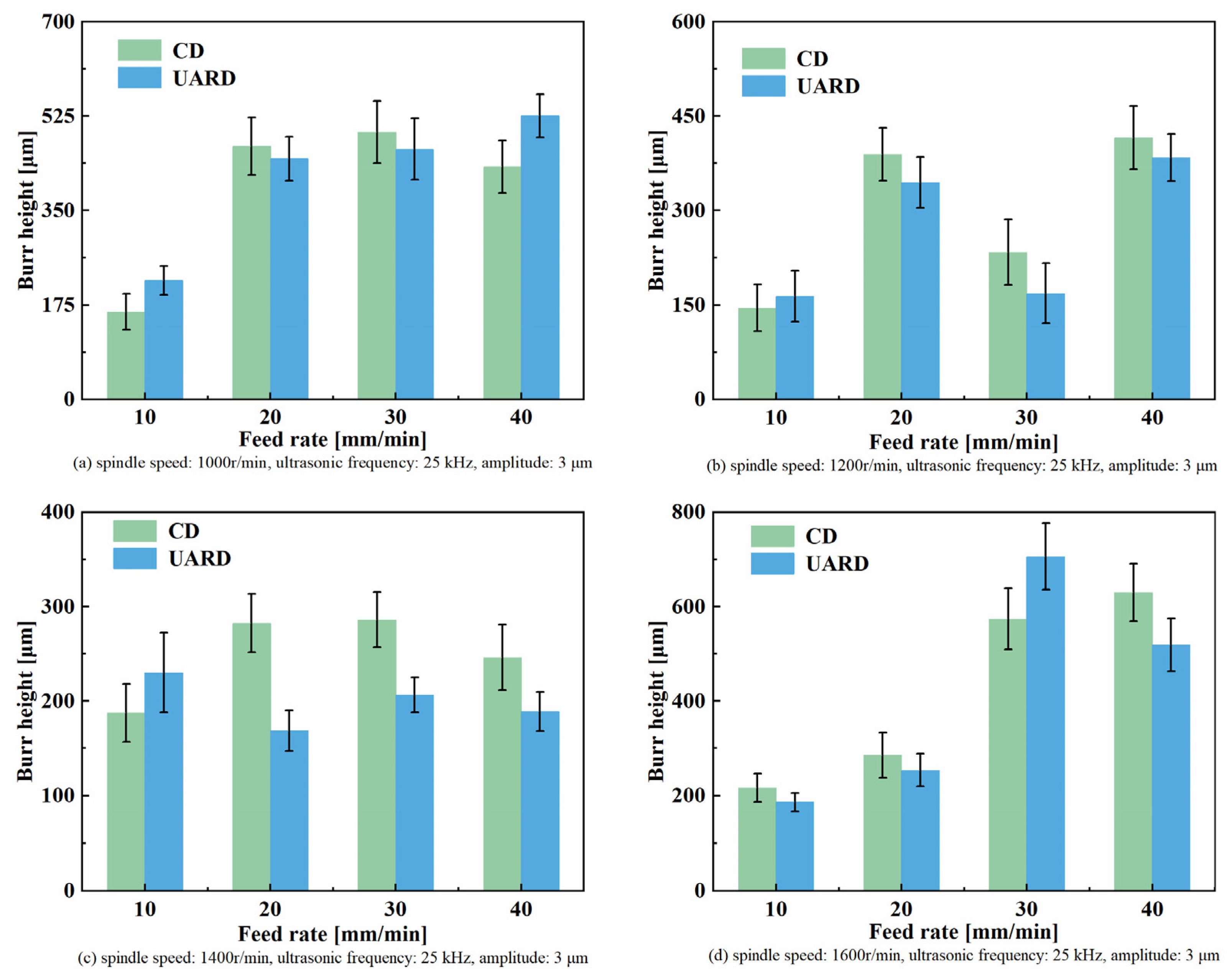
6.4. CFRP Entrance Burr Height

The CFRP entrance burr generated by the cutting force and the Ti alloy chip discharge scratch is the major determining factor in assembly and component failure. Therefore, the burr height should be reduced as much as possible in the machining process. The entrance burr height of CRD and UARD is compared as shown in Figure 18. According to the different machining parameters of the drilling experiment, the burr height at the entrance of the CFRP under different machining parameters is calculated in accordance with the methodology illustrated in Figure 19.
Figure 19 illustrates that burr height is relatively low at low feed rates. As the feed rate is increased, the CFRP entrance burr gradually increases relative to the minimum feed rate. The burr height under different machining parameters does not show the same trend. Due to the different chip states caused by different machining parameters in the process of drilling Ti alloy, during chip evacuation, high temperature chips would crush and scratch the CFRP hole wall, the scratch damage at the entrance of CFRP is also different during the discharge process, so the burr height shows an irregular state. At a spindle speed of 1400 r/min and a feed rate of 20 mm/min, the burr height of CRD and UARD are shown in Figure 18a and b, respectively. In contrast, the burr height of UARD is reduced by about 45%. It can be seen that the appropriate processing parameters of UARD can effectively reduce the burr height. Compared with CRD and UARD, the burr height processed by both increases with an increase in feed rate, but UARD is still better than CRD on the whole.

7. Conclusions

To enhance the quality of the entrance machining of the robotic drilling CFRP/Ti6Al4V stacks, the machining plane and the posture of the robot were initially optimized. Subsequently, the drilling parameters were selected in conjunction with ultrasonic-assisted machining technology, taking into account the vibration displacement during conventional robotic drilling and ultrasonic-assisted robotic drilling, the height of the burr at the CFRP entrance, and the CFRP entrance delamination factor. The following conclusions can be drawn:
(1)
By optimizing the calculated machining area and machining posture, the quality and stability of robotic drilling are improved.
(2)
Compared with conventional robotic drilling, in ultrasonic-assisted robotic drilling, the entrance quality of CFRP is improved and the vibration during the drilling process is significantly reduced.
(3)
At an ultrasonic vibration frequency of 25 kHz, an amplitude of 3 μm, a spindle speed of 1400 r/min, and a feed rate of 30 mm/min, the lowest CFRP entrance delamination factor obtained by ultrasonic-assisted robotic drilling was 1.09. Moreover, the CFRP entrance burr height obtained by ultrasonic-assisted robotic drilling is the lowest when the ultrasonic vibration frequency is 25 kHz, the amplitude is 3 μm, the spindle speed is 1600 r/min, and the feed rate is 10 mm/min, which is 186.3 μm.

Author Contributions

Conceptualization, H.Z. and Z.Z.; Methodology, H.Z., Z.Z., X.W. and Y.L.; Software, Z.Z. and Y.L.; Formal analysis, X.W.; Data curation, H.Z.; Writing—original draft, H.Z.; Writing—review & editing, F.J.; Visualization, Y.L.; Supervision, F.J.; Project administration, F.J.; Funding acquisition, F.J. All authors have read and agreed to the published version of the manuscript.

Funding

This study was supported by the National Natural Science Foundation of China (No. 51675164).

Data Availability Statement

The data presented in this study are available on request from the corresponding author. The data are not publicly available due to privacy.

Conflicts of Interest

The authors declare no conflict of interest.

References

  1. Caro, S.; Dumas, C.; Garnier, S.; Furet, B. Workpiece Placement Optimization for Machining Operations with a KUKA KR270-2 Robot. In Proceedings of the 2013 IEEE International Conference on Robotics and Automation, Karlsruhe, Germany, 6–10 May 2013; IEEE: Karlsruhe, Germany; pp. 2921–2926. [Google Scholar]
  2. Leali, F.; Vergnano, A.; Pini, F.; Pellicciari, M.; Berselli, G. A Workcell Calibration Method for Enhancing Accuracy in Robot Machining of Aerospace Parts. Int. J. Adv. Manuf. Technol. 2016, 85, 47–55. [Google Scholar] [CrossRef]
  3. Schneider, U.; Drust, M.; Ansaloni, M.; Lehmann, C.; Pellicciari, M.; Leali, F.; Gunnink, J.W.; Verl, A. Improving Robotic Machining Accuracy through Experimental Error Investigation and Modular Compensation. Int. J. Adv. Manuf. Technol. 2016, 85, 3–15. [Google Scholar] [CrossRef]
  4. Pan, Z.; Zhang, H.; Zhu, Z.; Wang, J. Chatter Analysis of Robotic Machining Process. J. Mater. Process. Technol. 2006, 173, 301–309. [Google Scholar] [CrossRef]
  5. Zhang, H.; Wang, J.; Zhang, G.; Gan, Z.; Pan, Z.; Cui, H.; Zhu, Z. Machining with Flexible Manipulator: Toward Improving Robotic Machining Performance. In Proceedings of the Proceedings, 2005 IEEE/ASME International Conference on Advanced Intelligent Mechatronics, Monterey, CA, USA, 24–28 July 2005; IEEE: Monterey, CA, USA, 2005; pp. 1127–1132. [Google Scholar]
  6. Liao, Z.-Y.; Li, J.-R.; Xie, H.-L.; Wang, Q.-H.; Zhou, X.-F. Region-Based Toolpath Generation for Robotic Milling of Freeform Surfaces with Stiffness Optimization. Robot. Comput.-Integr. Manuf. 2020, 64, 101953. [Google Scholar] [CrossRef]
  7. Slamani, M.; Gauthier, S.; Chatelain, J.-F. A Study of the Combined Effects of Machining Parameters on Cutting Force Components during High Speed Robotic Trimming of CFRPs. Measurement 2015, 59, 268–283. [Google Scholar] [CrossRef]
  8. Salisbury, J. Active Stiffness Control of a Manipulator in Cartesian Coordinates. In Proceedings of the 1980 19th IEEE Conference on Decision and Control including the Symposium on Adaptive Processes, Albuquerque, NM, USA, 10–12 December 1980; IEEE: Albuquerque, NM, USA, 1980; pp. 95–100. [Google Scholar]
  9. Abele, E.; Weigold, M.; Rothenbücher, S. Modeling and Identification of an Industrial Robot for Machining Applications. CIRP Ann. 2007, 56, 387–390. [Google Scholar] [CrossRef]
  10. Chen, C.; Peng, F.; Yan, R.; Li, Y.; Wei, D.; Fan, Z.; Tang, X.; Zhu, Z. Stiffness Performance Index Based Posture and Feed Orientation Optimization in Robotic Milling Process. Robot. Comput.-Integr. Manuf. 2019, 55, 29–40. [Google Scholar] [CrossRef]
  11. Celikag, H.; Sims, N.D.; Ozturk, E. Cartesian Stiffness Optimization for Serial Arm Robots. Procedia CIRP 2018, 77, 566–569. [Google Scholar] [CrossRef]
  12. Bu, Y.; Liao, W.; Tian, W.; Zhang, J.; Zhang, L. Stiffness Analysis and Optimization in Robotic Drilling Application. Precis. Eng. 2017, 49, 388–400. [Google Scholar] [CrossRef]
  13. Guo, Y.; Dong, H.; Ke, Y. Stiffness-Oriented Posture Optimization in Robotic Machining Applications. Robot. Comput.-Integr. Manuf. 2015, 35, 69–76. [Google Scholar] [CrossRef]
  14. Liao, Z.; Wang, Q.-H.; Xie, H.; Li, J.-R.; Zhou, X.; Hua, P. Optimization of Robot Posture and Workpiece Setup in Robotic Milling with Stiffness Threshold. IEEE/ASME Trans. Mechatron. 2022, 27, 582–593. [Google Scholar] [CrossRef]
  15. Lu, Y.-A.; Tang, K.; Wang, C.-Y. Collision-Free and Smooth Joint Motion Planning for Six-Axis Industrial Robots by Redundancy Optimization. Robot. Comput.-Integr. Manuf. 2021, 68, 102091. [Google Scholar] [CrossRef]
  16. Diaz Posada, J.; Schneider, U.; Sridhar, A.; Verl, A. Automatic Motion Generation for Robotic Milling Optimizing Stiffness with Sample-Based Planning. Machines 2017, 5, 3. [Google Scholar] [CrossRef]
  17. Garnier, S.; Dumas, C.; Caro, S.; Furet, B. Quality Certification and Productivity Optimization in Robotic-Based Manufacturing. IFAC Proc. Vol. 2013, 46, 825–830. [Google Scholar] [CrossRef]
  18. Tunc, L.T.; Gonul, B. Effect of Quasi-Static Motion on the Dynamics and Stability of Robotic Milling. CIRP Ann. 2021, 70, 305–308. [Google Scholar] [CrossRef]
  19. Kratena, T.; Vavruska, P.; Sveda, J.; Valasek, M. Postprocessor for Verification of Robot Movements with Additional Axis after Toolpath Optimization. Procedia CIRP 2021, 101, 154–157. [Google Scholar] [CrossRef]
  20. Tepper, C.; Matei, A.; Zarges, J.; Ulbrich, S.; Weigold, M. Optimal Design for Compliance Modeling of Industrial Robots with Bayesian Inference of Stiffnesses. Prod. Eng. Res. Devel. 2023, 17, 643–651. [Google Scholar] [CrossRef]
  21. Kumar, D.; Gururaja, S. Investigation of Hole Quality in Drilled Ti/CFRP/Ti Laminates Using CO2 Laser. Opt. Laser Technol. 2020, 126, 106130. [Google Scholar] [CrossRef]
  22. Huo, Y.; Niu, Y.; Sun, Z.; Li, Y.; Niu, J. Surface/Subsurface Damage Mechanisms and Inhibition Strategies in Machining of Hard and Brittle Materials: A Systematic Review. Surf. Interfaces 2024, 54, 105088. [Google Scholar] [CrossRef]
  23. Onawumi, P.Y.; Roy, A.; Silberschmidt, V.V.; Merson, E. Ultrasonically Assisted Drilling of Aerospace CFRP/Ti Stacks. Procedia CIRP 2018, 77, 383–386. [Google Scholar] [CrossRef]
  24. Wang, C.; Li, P.; Li, S.; Qiu, X.; Niu, Q.; Li, C.; Ko, T.J. Study on the Mechanism and Performance of Longitudinal-Torsional Ultrasonic Vibration Assisted Drilling CFRP/Ti Stack. J. Manuf. Process. 2023, 92, 453–465. [Google Scholar] [CrossRef]
  25. Ma, G.; Kang, R.; Dong, Z.; Yin, S.; Bao, Y.; Guo, D. Hole Quality in Longitudinal–Torsional Coupled Ultrasonic Vibration Assisted Drilling of Carbon Fiber Reinforced Plastics. Front. Mech. Eng. 2020, 15, 538–546. [Google Scholar] [CrossRef]
  26. Dong, S.; Zheng, K.; Liao, W. Stability of Lateral Vibration in Robotic Rotary Ultrasonic Drilling. Int. J. Mech. Sci. 2018, 145, 346–352. [Google Scholar] [CrossRef]
  27. Zargarbashi, S.H.H.; Khan, W.; Angeles, J. The Jacobian Condition Number as a Dexterity Index in 6R Machining Robots. Robot. Comput.-Integr. Manuf. 2012, 28, 694–699. [Google Scholar] [CrossRef]
  28. Alici, G.; Shirinzadeh, B. Enhanced Stiffness Modeling, Identification and Characterization for Robot Manipulators. IEEE Trans. Robot. 2005, 21, 554–564. [Google Scholar] [CrossRef]
  29. Zargarbashi, S.H.H.; Khan, W.; Angeles, J. Posture Optimization in Robot-Assisted Machining Operations. Mech. Mach. Theory 2012, 51, 74–86. [Google Scholar] [CrossRef]
  30. Jiao, J.; Tian, W.; Liao, W.; Zhang, L.; Bu, Y. Processing Configuration Off-Line Optimization for Functionally Redundant Robotic Drilling Tasks. Robot. Auton. Syst. 2018, 110, 112–123. [Google Scholar] [CrossRef]
  31. Liu, F.; Chen, T.; Duan, Z.; Suo, Y.; Zhang, C. Ultrasonic Assisted Pecking Drilling Process for CFRP/Ti Laminated Materials. J. Manuf. Process. 2023, 108, 834–851. [Google Scholar] [CrossRef]
Figure 1. ABB IRB-6700 robot kinematic model.
Machines 12 00881 g001
Figure 2. Stiffness ellipsoid at TCP of end-effector.
Machines 12 00881 g002
Figure 3. (a,b) The influence of ja2 and ja3 and ja4 and ja5 on Kc.
Machines 12 00881 g003
Figure 4. The Kc distribution in the space after the optimization of the rotation range of ja2 and ja3.
Machines 12 00881 g004
Figure 5. Stiffness distribution of machining plane with different heights.
Machines 12 00881 g005
Figure 6. Robot redundancy schematic diagram.
Machines 12 00881 g006
Figure 7. Variation trend of Kz with β.
Machines 12 00881 g007
Figure 8. Experimental platform and device.
Machines 12 00881 g008
Figure 9. Experimental tools and materials. (a) Carbide twist drill; (b) CFRP and Ti6A14V.
Machines 12 00881 g009
Figure 10. Robotic ultrasonic drilling system.
Machines 12 00881 g010
Figure 11. Vibration displacement in the drilling process of machining planes with different heights.
Machines 12 00881 g011
Figure 12. The variation trend of vibration displacement with redundancy angle.
Machines 12 00881 g012
Figure 13. Vibration signals in the process of CRD and UARD.
Machines 12 00881 g013
Figure 14. Vibration in CRD and UARD process under different drilling parameters. (a) spindle speed: 1000 r/min, ultrasonie frequeney: 25 kHz, amplitude: 3 μm; (b) spindle speed: 1200 r/min, ultrasonie frequeney: 25 kHz, amplitude: 3 μm; (c) spindle speed: 1400 r/min, ultrasonic frequency: 25 kHz, amplitude: 3 μm; (d) spindle speed: 1600 r/min, ultrasonie frequeney: 25 kHz, amplitude: 3 μm.
Machines 12 00881 g014
Figure 15. Delamination damage of CRD and UARD under different feed rates (1200 r/min).
Machines 12 00881 g015
Figure 16. Evaluation method of CFRP entrance damage.
Machines 12 00881 g016
Figure 17. Fd in CRD and UARD under different drilling parameters. (a) spindle speed: 1000 r/min, ultrasonic frequency: 25 kHz, amplitude: 3 μm; (b) spindle speed: 1200 r/min, ultrasonic frequency: 25 kHz, amplitude: 3 μm; (c) spindle speed: 1400 r/min, ultrasonic frequency: 25 kHz, amplitude: 3 μm; (d) spindle speed: 1600 r/min, ultrasonic frequency: 25 kHz, amplitude: 3 μm.
Machines 12 00881 g017
Figure 18. CRD and UARD (frequency is 25 KHz, amplitude is 3 μm) burr height under spindle speed: 1400 r/min; feed rate: 20 mm/min.
Machines 12 00881 g018
Figure 19. The burr height of CFRP entrance in CRD and UARD under different drilling parameters. (a) spindle speed: 1000 r/min, ultrasonic frequency: 25 kHz, amplitude: 3 μm; (b) spindle speed: 1200 r/min, ultrasonic frequency: 25 kHz, amplitude: 3 μm; (c) spindle speed: 1400 r/min, ultrasonic frequency: 25 kHz, amplitude: 3 μm; (d) spindle speed: 1600 r/min, ultrasonic frequency: 25 kHz, amplitude: 3 μm.
Machines 12 00881 g019
Table 1. Modified D-H parameters and range of joint angle rotation of IRB-6700.
Link iai1 [mm]αi1 [°]di [mm]θi [°]Range of Joint Angle [°]
1007800−170~170
2320−900−90−60~85
31125000−180~70
4200−901142.50−300~300
509000−130~130
60−90200180−360~360
i represents the coordinate system of joint I; αi−1 represents the angle of the zi−1 axis, rotating along the xi−1 axis to the zi axis; ai−1 is the distance from zi1 to zi along xi−1; θi is the angle of xi−1 rotating to xi; and di is the distance from xi−1 to xi along zi.
Table 2. Mechanical properties of unidirectional CFRP plate.
PropertiesValue
Tensile strength [MPa]5523
Modulus of elongation [GPa]252
Density [g/cm3]1.81
Breaking elongation [%]2.1
Table 3. Mechanical properties of Ti6Al4V.
PropertiesValue
Density [g/cm3]4.52
Poisson ratio [-]0.343
Tensile strength [MPa]902
Yield strength [MPa]824
Elongation [%]10
Shrinkage ratio [%]30
Table 4. Experimental conditionals.
VariablesValue
Spindle speed [r/min]1000, 1200, 1400, 1600
Feed rate [mm/min]10, 20, 30, 40
Ultrasonic vibration frequency [kHz]25, 0
Ultrasonic amplitude [μm]3, 0
Disclaimer/Publisher’s Note: The statements, opinions and data contained in all publications are solely those of the individual author(s) and contributor(s) and not of MDPI and/or the editor(s). MDPI and/or the editor(s) disclaim responsibility for any injury to people or property resulting from any ideas, methods, instructions or products referred to in the content.

