1. Introduction
The rotor system serves as a fundamental component of an aero-engine, primarily consisting of crucial parts such as the high-pressure compressor rotor and high-pressure turbine rotor, which are assembled into a unified whole through coupling devices. Before being reassembled and interconnected, both the compressor and turbine rotors undergo individual dynamic balancing. However, unbalanced faults in the rotors frequently lead to excessive vibration of the entire aero-engine [
1]. Especially in extreme operating conditions, characterized by high temperatures, high pressures, and high speeds, unbalanced conditions are significantly amplified, exceeding controllable limits and potentially causing severe faults such as blade rubbing, which poses a severe threat to the longevity of the aero-engine [
2]. Therefore, the accurate identification of unbalanced positions within the rotor system, followed by effective prediction, monitoring, and control of unbalance vibrations, has emerged as a critical technical challenge that demands immediate attention and innovative solutions.
Investigating the dynamic characteristics of rotor systems and constructing corresponding dynamic models can reveal the motion laws and vibration characteristics of rotors under complex operating conditions, thereby providing theoretical support for the identification and diagnosis of unbalance faults. In terms of dynamic modeling of rotor systems, the primary methods encompass the analytical method [
3,
4,
5], the lumped parameter method [
6,
7,
8], the transfer matrix method [
9], and the finite element method [
10,
11,
12,
13]. Zhao et al. [
3] established an analytical model for a flexible shaft-disk-drum rotor, examining the influence patterns of uncertain parameters on the vibration response of rotor systems with elastic supports. Miao et al. [
4] built a rotor dynamic model considering the coupling of the coupling shaft based on the analytical method and subsequently explored the nonlinear vibration characteristics of the system on this basis, analyzing the characteristics of friction faults. Luo et al. [
6] adopted the lumped mass method to establish a coupling model for rotor systems, taking into account angular misalignment and analyzed the influence of structural parameters of squeeze film dampers on the nonlinear vibration characteristics of the system. Li et al. [
7] further established a lumped mass model for bolted-disk joints, deeply discussing the significant impact of tangential stiffness and bending stiffness at bolted connections on the vibration response of the system. Gupta et al. [
9] utilized the extended transfer matrix method to establish a dynamic model for dual-rotor systems, studying the effects of rotational inertia and gyroscopic moments on the dynamic characteristics of the system and conducting a stability analysis of the system. Qin et al. [
10] derived an analytical model for the bending stiffness of disk-drum connection structures and introduced it into the finite element model of rotor systems, solving the dynamic equations of rotor systems using the harmonic balance method. Lu et al. [
11] established a finite element model for dual-rotor systems with breathing cracks and analyzed the dynamic response of these systems using the harmonic balance method. Chen et al. [
12] considered spatial crack faults to establish a finite element model for gear-rotor systems, analyzing the impact of gear mesh stiffness and cracks on mesh stiffness and the vibration response of the system.
Rotor unbalance can induce severe vibrations in aero-engines, with the majority of mechanical failures in such engines being vibration-induced or vibration-related [
14,
15,
16,
17,
18,
19]. Therefore, an in-depth analysis of the influence patterns of rotor unbalance on system vibration characteristics is particularly significant. Numerous scholars have conducted extensive research on this issue. Yu et al. [
14] performed dynamic modeling of a dual-rotor system in an aero-engine and found that, during the operation of turbofan engines, rotor blades not only introduce sudden unbalances and inertial asymmetries but also impose significant impact loads, leading to friction between the rotor and stator. Wang et al. [
15] established a dynamic model that considered the nonlinear force coupling effects of squeeze film dampers and intermediate bearings in a dual-rotor system under multiple unbalanced forces. Through simulations, they observed that the rotor system exhibits quasi-periodic motion with four cycles near the critical speed. Yang et al. [
16] addressed the issue of fixed-point friction in aero-engines by developing a mechanical vibration model for a dual-rotor system under the coupling effects of two unbalanced rotors and fixed-point friction. Chen et al. [
20,
21] proposed an assembly optimization method for multi-stage rotors in a specific type of aero-engine, using coaxiality and unbalance parameters as dual objective functions and employing genetic algorithms to solve for the optimal assembly angles of rotors at various stages. Song et al. [
22] established a prediction model for unbalance in multi-stage assembled rotors, accurately forecasting bilateral unbalances and their acting phases in multi-stage rotors. In summary, the influence of rotor unbalance on the vibration characteristics of aero-engine is a complex and important issue. By conducting in-depth research on this issue, not only can the operational stability and reliability of aero-engines be improved, but valuable support can also be provided for the design and optimization of aero-engines.
Rotor unbalance can exacerbate vibrations in aero-engines, adversely impacting their operational stability and service life. In response to this challenge, numerous scholars have conducted in-depth research. Jiang et al. [
23] proposed a method for dynamic unbalance compensation by generating control signals based on the real-time position of the rotor’s unbalanced mass. They analyzed the control performance under different unbalance phases, optimization step sizes, and noise levels. Ma et al. [
24] delved into the impact of unbalanced rotor vibration coupling, vibration transmission, and sensitivity on overall machine vibration and dynamic balance, revealing the intricate mechanisms through which unbalanced location, magnitude, and phase influence rotor vibration response. Wang et al. [
25] further explored the influence of rotational speed and rotor unbalance on the deviation between static and dynamic balance positions of the rotor. They discovered that, under the influence of rotational unbalanced forces, there is a significant deviation between the rotor’s dynamic and static balance positions, and this deviation approximates a linear relationship with rotational speed. Therefore, accurately identifying the unbalanced rotor position is crucial for precise fault diagnosis and rapid response. However, traditional methods for identifying unbalanced rotor positions often rely on empirical judgments and extensive test data, making it challenging to accurately capture subtle changes in unbalanced vibrations. With the advancement of signal processing technology and machine learning algorithms, in-depth analysis of vibration data can be conducted to achieve real-time monitoring and precise identification of unbalanced states, providing strong support for preventive maintenance and health management of engines. Han et al. [
26,
27] proposed a transfer learning method for unbalanced rotor fault localization that combines finite element models of rotor dynamics with experimental data. Although it achieves unbalanced rotor position identification to a certain extent, its accuracy and efficiency still require further enhancement.
In the research of rotor unbalance issues, Artificial Neural Networks (ANNs) have demonstrated immense potential in assisting the dynamic balancing process. Compared to traditional dynamic balancing methods, which often rely on experience and manual adjustments, ANNs can automatically adjust the rotor’s balance state by deeply learning and simulating critical data such as vibration signals, thereby enhancing the precision and efficiency of rotor balancing. Santos et al. [
28] established an analytical model for rotor systems supported by sliding bearings, utilizing plane separation techniques and ANNs to predict the position and magnitude of the balance correction masses for rotor systems. This method provides an effective pathway for continuous monitoring of dynamic balancing in rotating machinery. Walker et al. [
29] further employed a data-driven approach, utilizing ANNs to achieve automatic localization of rotor unbalance and incorporating friction and misalignment faults into their research to validate the system’s stability and reliability. Yan et al. [
30] proposed an unbalanced rotor fault diagnosis method based on the Deep Belief Network (DBN), which can automatically learn typical features of rotor unbalance faults and accurately identify unbalance fault states. Zhong et al. [
31,
32] introduced a rotor balancing method based on unsupervised deep learning, capable of efficiently determining the magnitude and position of unbalance in two correction planes. Xing et al. [
33] utilized Convolutional Neural Networks (CNNs) to detect the magnitude and position of dynamic unbalance in wind turbine rotors, with the natural modal functions of nacelle vibrations as the input variables, successfully discerning weak unbalance signals. Long Short-Term Memory (LSTM) networks, a variant of Recurrent Neural Networks (RNNs) designed for processing sequential data [
34,
35], have exhibited exceptional performance in many application scenarios due to their ability to learn and remember long-term dependencies. In the research of unbalanced rotor issues, LSTM networks also have broad application prospects and are anticipated to provide innovative solutions for the intellectualization and automation of rotor balancing processes.
This paper is organized as follows: In
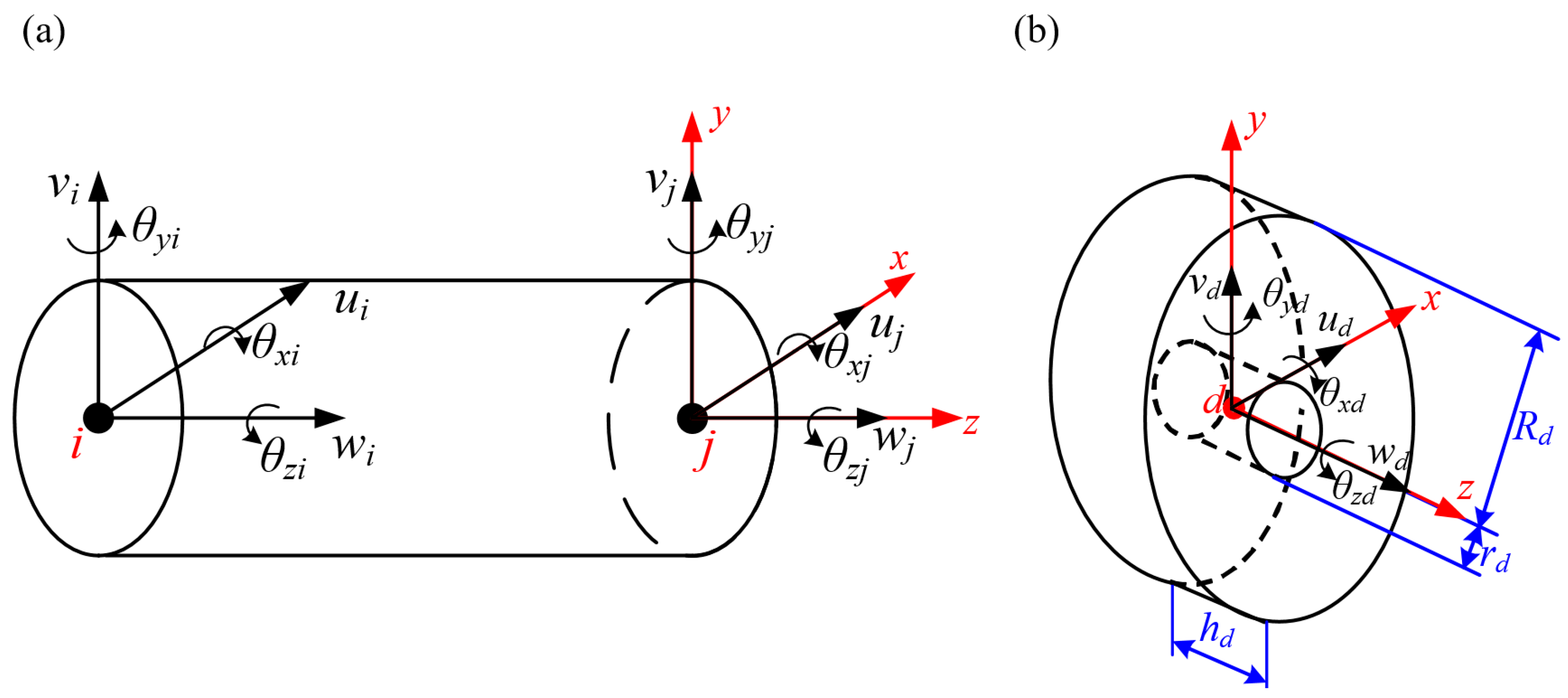
Section 2, the dynamic model of the rotor system is established using the finite element method, comprehensively considering the shaft, disks, support elements, and couplings. Following the establishment of the model, a rotor test tig is constructed, and preliminary modal validation is conducted to ensure the accuracy and reliability of the model. This validation step is crucial as it provides a solid foundation for subsequent experiments and analyses. In
Section 3, vibration response experiments and simulation studies are carried out on the rotor system. These experiments are designed to assess the system’s behavior at four different unbalanced positions and under various rotational speeds. The results obtained from these experiments further confirm the accuracy and reliability of the established dynamic model, reinforcing our confidence in its predictive capabilities. Additionally, an LSTM neural network structure is constructed, and deep training and intelligent analysis are performed on rotor vibration data. This advanced analysis enables us to effectively identify the rotor’s unbalanced positions, which is a critical step in fault diagnosis and predictive maintenance. In
Section 4, the identification results are analyzed and discussed.
Section 5 summarizes the research conclusions of this paper. The innovation of this paper lies in the first application of the LSTM neural network to identify the unbalanced position of an aero-engine turbine rotor. LSTM networks are particularly suitable for processing time-varying vibration signal sequence data, which makes them ideal for dealing with unbalanced position identification problems. By training the LSTM model on a comprehensive dataset containing experimental and simulation data at different speeds, it is able to learn complex relationships between vibration patterns and unbalanced positions.
3. Rotor Vibration Response and Unbalance Position Identification
In the previous section, the accuracy of the established dynamic model has been preliminarily verified by analyzing the inherent characteristics of the rotor system. To thoroughly validate the accuracy of the constructed dynamic model, a constant-speed test is conducted on the built test rig. During the testing process, vibration response data of the rotor system at various rotational speeds are meticulously recorded. A comprehensive comparison between these experimental data and the unbalanced vibration responses predicted by the finite element model is performed, further confirming the high accuracy and reliability of the established dynamic model. On this basis, through the construction of neural network architecture, the vibration signal data based on the measured data and the simulation data are deeply trained and intelligent analysis so as to identify the unbalanced position of the rotor, which provides a new method and method for improving the accuracy and reliability of the rotor balance.
3.1. Vibration Response Analysis of Rotor System at Different Speed
Based on
Section 2.2, the first-order critical speed of the experimental system in this paper is determined to be 7260 rpm. To comprehensively evaluate the dynamic response of the rotor under different rotational speeds, constant-speed tests are conducted at subcritical (5600 rpm), critical (7260 rpm), and supercritical (8400 rpm) speeds. In the test, we set an unbalance of approximately 15 gmm millimeters (gmm) using a balance chuck to induce an observable unbalance response. This setting is designed to simulate the imbalances that may be encountered in actual operation and to assess their impact on system performance. Unbalance response analysis is an important part of rotating machinery fault diagnosis, through which we can understand the effects of unbalance on vibration, noise, and service life of the system. To verify the accuracy of the model, the signals collected by the eddy current sensor at measurement point 3 are selected for detailed analysis and comparison. The eddy current sensor is a non-contact measuring tool that accurately captures small vibration changes during the operation of rotating machinery. By comparing the measured signal with the simulation results, we can assess the predictive power of the model and identify potential sources of error.
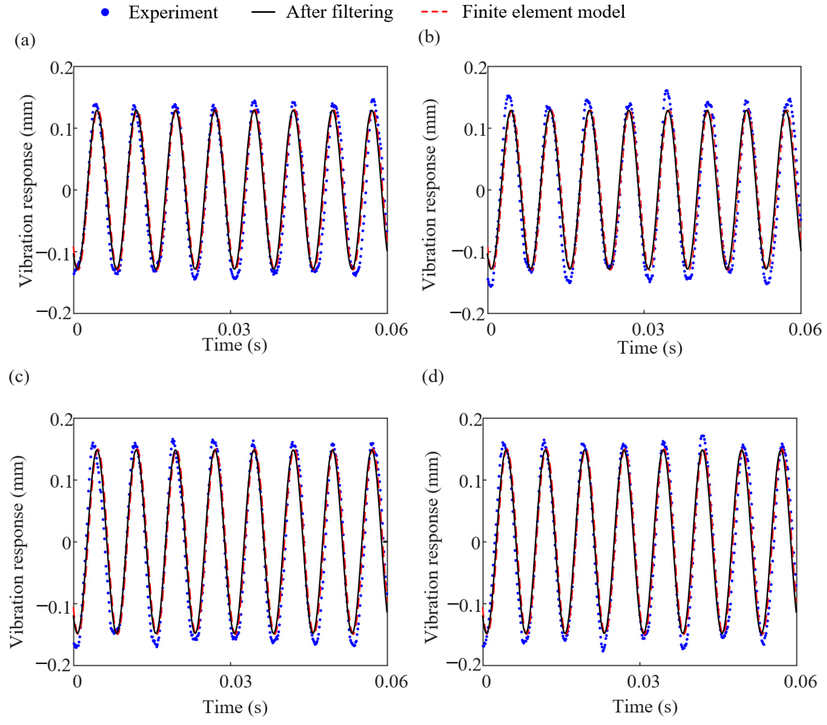
It is noteworthy that the actual rotor test bench possesses a relatively complex structure, incorporating various friction coupling elements such as bearings and bolted connections, which may introduce nonlinear phenomena within the system. Consequently, the measured signals often exhibit greater complexity compared to simulated signals. Theoretically, unbalance solely induces rotational frequency components. However, in practical scenarios, other nonlinear frequency components may also influence the signals. To more accurately analyze the unbalanced response, band-pass filtering technology is used to eliminate the impact of other nonlinear frequencies, retaining only the rotational frequency components of the measured signals. This processing step is crucial for precisely identifying unbalanced responses.
In summary, vibration experiments are conducted at four different unbalanced positions under subcritical (5600 rpm), critical (7260 rpm), and supercritical (8400 rpm) conditions. At the same time, based on the established rotor finite element model, the unbalance is added to the corresponding position of the experiment to calculate the system vibration response. The experimental results are then compared with the simulation results. The comparison results are illustrated in
Figure 6,
Figure 7 and
Figure 8.
Through in-depth analysis of the experimental data, we can observe that, under the condition of exceeding the critical speed, the filtered experimental results of the rotor system exhibit a high degree of consistency with the simulation results. This comparison, to a certain extent, validates the rationality and accuracy of the established dynamic model. Specifically, the experimental waveform aligns well with the simulation waveform in terms of shape, amplitude, and phase. However, under subcritical and critical speed conditions, the time-domain waveform of the rotor system shows certain discrepancies. These discrepancies may primarily arise from the complexity of the test bench system. Specifically, the interfacial contact friction of components such as bearings and bolts within the test bench may more readily induce nonlinear behavior in the system. These nonlinear factors may include but are not limited to, variations in friction force, minute deformations at the contact interfaces, and the additional vibrations resulting from these. These factors collectively contribute to a certain deviation between the experimental waveform and the simulation waveform. To gain a deeper understanding of these discrepancies and further improve the accuracy of the model, future research should strengthen the study of nonlinear behavior in the test bench system, including the establishment of more precise nonlinear dynamic models.
3.2. Long Short-Term Memory Neural Network
In the research of high-speed dynamic balancing of flexible rotors, the identification of unbalanced rotor positions has always been a challenging problem. Especially for slender rotors, the axial location of unbalance has a significant impact on the high-speed dynamic balancing of the rotor. In recent years, deep learning, as a powerful machine learning technique, has achieved remarkable results in fields such as image recognition and speech recognition. In the area of unbalanced rotor position identification, deep learning techniques based on limited labeled data have also demonstrated great potential. By training deep neural networks, effective feature information can be extracted from the limited labeled data, thereby enabling accurate identification of unbalanced positions.
The LSTM (Long Short-Term Memory) network significantly enhances the neural network’s capability in processing time-series data by introducing memory cells and control units such as input gates, forget gates, and output gates. The core of its working mechanism lies in the self-looping and feedback mechanism of the internal state of the memory cells. This mechanism, combined with sophisticated gating strategies, regulates the inflow and outflow of information streams, achieving effective truncation of error signals. This ensures the stability and integrity of errors during the backward propagation process, thereby avoiding common issues in traditional recurrent neural networks, such as gradient vanishing or gradient exploding.
Figure 9 provides a detailed illustration of the structural composition of the LSTM unit.
The computational process of LSTM can be divided into three stages based on its three gate structures: the forget stage, the input stage, and the output stage. During the forget stage, the forget gate assesses the significance of the information in the cell state at time (
t − 1) and selects whether to retain or discard it. The important information that is retained is then passed on to the input stage:
where
and
are the weight matrix and bias vector of the forgetting gate, respectively,
is the Sigmoid activation function,
represents the output value of the network hidden layer at time (
t − 1) and
is the input parameter of the structure at time
t. In addition, when
, it represents the cell state of (
t − 1) at the moment of complete abandonment, while when
, it represents the cell state of complete retention of (
t − 1).
The input stage mainly stores the input data at time (
t − 1) and the important information in the hidden state at time
t in the cell state through the relevant calculation of the input gate:
where
Wu and
Wp are the weight matrices of input gate and loop cell states, respectively,
bu and
bp are the bias vectors of the input gate and the loop unit, respectively, and
represents the element-by-element product operation between vectors.
The output phase mainly determines the output of the LSTM unit at time
t through the output gate:
where
Ct and
Ct−1 are the output of the memory unit at time
t and (
t − 1), respectively.
Wo and
bo are the weight matrix and bias vector of the output stage, respectively. For a single-output network, the output of the output layer is represented as follows:
where
Yt is the corresponding matrix of
Xt at time
t, and
WY and
bY are the weight matrix and bias vector of the output gate.
3.3. Unbalanced Position Identification of Rotor Based on LSTM
In flexible rotor systems, unbalance is one of the primary causes of vibration and noise. For slender rotors, due to their long axial extension, the occurrence of unbalance at different locations will directly affect the dynamic characteristics and stability of the rotor. Therefore, accurately identifying the axial location of unbalance is of great significance for achieving high-speed dynamic balancing of the rotor and improving the overall performance of rotating machinery.
3.3.1. Data Preprocessing
Initially, four unbalanced positions, A, B, C, and D, are selected on the constructed rotor test bench, with their specific layout illustrated in
Figure 5. At each of these positions, an unbalanced mass of 15 gmm with a phase of 30° is manually added to obtain the measured vibration response of the rotor at each unbalanced position. To ensure the accuracy and reliability of the data, preprocessing steps are taken to eliminate noise and outliers from the raw data. Furthermore, dynamic simulations are performed with consistent parameter settings to calculate the vibration displacement of the nodes. Based on this, both filtered measured vibration data and dynamic model simulation data are collected, covering vibration responses under different unbalanced positions (A, B, C, D). This provides a reliable data foundation for subsequent model training and validation. Given the significant advantages of LSTM models in processing sequential data, the vibration data are arranged in time series to form input sequences. To facilitate the recognition and classification of unbalanced positions by the LSTM model, the unbalanced positions (A, B, C, D) are converted into corresponding numerical labels for model recognition and classification.
3.3.2. Optimization Model Construction
In designing the LSTM neural network for rotor imbalance position recognition, careful consideration is given to the choice of network structure. Since an unbalanced distribution state corresponds to the vibration data composed of four measurement points of the rotor, the number of nodes in the input layer of the designed neural network is 4. Hidden Layer determines the ability of neural networks to learn features, and the number of hidden layers and nodes determines the complexity of the network to process data and the mapping ability of complex functions. In general, the formula for calculating the number of hidden layer nodes is as follows:
where
nm indicates the number of hidden layer nodes,
nx is the number of nodes in the input layer,
ny is the number of nodes in the output layer, and
a is the constant between the intervals [1, 10].
In addition, the choice of activation function is crucial for the performance of neural networks. In this case, the Sigmoid function is selected for the hidden layers compared to other activation functions like ReLU; the Sigmoid function has a smoother gradient that can help mitigate issues with gradient vanishing, especially in deeper networks. Additionally, its output range is well-suited for representing probabilities, although this is not directly leveraged in the output layer, which instead uses the Softmax function for classification. The Sigmoid function’s properties made it a suitable choice for enhancing the network’s nonlinear processing capabilities and improving its generalization performance on the rotor imbalance position recognition task. Following the LSTM layers, fully connected layers are added for feature extraction and classification. The output layer employed the Softmax function, which converted the outputs of the fully connected layer into a probability distribution, indicating the likelihood of each possible rotor imbalance position. Overall, the constructed multi-layer regression LSTM neural network model, as illustrated in
Figure 10, is designed to strike an optimal balance between network complexity and convergence speed, making it well-suited for the task of rotor imbalance position recognition.
3.3.3. Model Training
The preprocessed data is divided into training, validation, and test sets, which are respectively utilized for model training, validation, and evaluation. For the purpose of model training and optimization, the cross-entropy loss function and Adam optimizer are selected. The training set data is input into the LSTM model for multiple iterations of training, continuing until the model’s performance on the validation set stabilizes or begins to decline. It is noteworthy that the loss function serves as a crucial metric in neural network training, quantifying the error between the network’s output and the desired output. A lower loss function value indicates better network performance. During the training process, the loss function value for all samples in the training set is calculated in each iteration, and the weights and biases of the neural network are updated according to the optimizer settings to minimize the loss function value. Simultaneously, the validation set is used to evaluate the network’s performance and generalization ability, ensuring that the model does not suffer from overfitting. The loss curve during the training process at a subcritical rotational speed of 5600 rpm, as shown in
Figure 11, demonstrates that the model exhibits good performance on both the training and validation data.
4. Discussion
At present, researchers have explored various techniques for unbalanced identification in rotating machinery. Traditional methods often involve vibration analysis using Fast Fourier Transform (FFT) or other signal processing techniques to detect harmonic components indicative of unbalance. However, these methods can be limited in their ability to accurately pinpoint the exact location of the unbalance, especially in complex systems like aero engines. More advanced approaches, such as those utilizing machine learning algorithms, have emerged in recent years. While these methods have shown promise, they may struggle with the temporal dependencies inherent in vibration data, which can be crucial for accurate identification.
To solve the difficult problem of unbalanced position identification of an aero-engine rotor, a method of unbalanced position identification of an aero-engine power turbine rotor based on the LSTM is proposed. This method addresses this limitation by capturing the long-term dependencies in the vibration signals. LSTM networks are particularly well-suited for sequential data analysis, making them ideal for processing vibration signals recorded over time. By training the LSTM model on a comprehensive dataset that includes both experimental and simulation data from different rotational speeds, the method is able to learn the complex relationships between vibration patterns and unbalanced positions. The unbalanced position is identified by the neural network model trained by experimental data and simulation data at different rotational speeds. The results are as follows:
(1) At a subcritical rotational speed of 5600 rpm, the measured unbalanced rotor vibration response data from the test bench and the vibration response data obtained through simulation are input into the LSTM model for training, with the aim of identifying the unbalanced rotor position. The results of unbalanced rotor position identification based on the LSTM model are presented in
Figure 12.
Figure 12a shows that the accuracy of identification results based on measured data can be controlled above 97.5%, with an impressive 100% accuracy when unbalanced masses are present at positions B and D.
Figure 12b demonstrates that the accuracy of identification results based on simulated data can be maintained above 91.2%, achieving a perfect 100% accuracy specifically when an unbalanced mass is at position B. These results validate the effectiveness of the proposed method in identifying unbalanced positions at subcritical speeds.
(2) According to the experimental test results, the first-order critical speed of the rotor system is 7260 rpm. Therefore, by varying four unbalanced positions at the critical speed, the unbalanced vibration response data measured on the test bench and the vibration response data calculated through simulations are input into the LSTM model for training in order to identify the unbalanced position of the rotor at the critical speed, as shown in
Figure 13.
Figure 13a indicates that the accuracy of identification results based on measured data can be maintained above 95.5%, with an impressive 100% accuracy, specifically when unbalanced masses are present at positions A and B.
Figure 13b demonstrates that the accuracy of identification results based on simulated data can be controlled above 93.1%, achieving a perfect 100% accuracy when an unbalanced mass is at position A. These results validate the effectiveness of the proposed method in identifying unbalanced positions at the critical speed.
(3) When varying four unbalanced positions at supercritical speed (8400 rpm), the unbalanced vibration response data measured on the test bench and the vibration response data calculated through simulations are input into the LSTM model for training in order to identify the unbalanced position of the rotor at supercritical speed, as shown in
Figure 14.
Figure 14a indicates that the accuracy of identification results based on measured data can be maintained above 97.8%, with an impressive 100% accuracy, specifically when unbalanced masses are present at positions A and B. Meanwhile,
Figure 14b demonstrates that the accuracy of identification results based on simulated data can be controlled above 90.5%, achieving a perfect 100% accuracy when an unbalanced mass is at position A. These results validate the effectiveness of the proposed method in identifying unbalanced positions at supercritical speed.
In summary, the LSTM-based approach offers superior performance in identifying unbalanced positions with high accuracy. Preliminary results, as presented earlier, indicate that the method can achieve accuracies above 90.5% for experimental data and above 95.5% for simulated data, with specific cases reaching perfect accuracy. By leveraging the strengths of LSTM networks and incorporating both experimental and simulation data, the method demonstrates the potential to overcome the limitations of traditional and other machine learning-based approaches, thereby enhancing the reliability and efficiency of aero engine maintenance and operation.
5. Conclusions
This paper focuses on the study of turbo-rotor systems in aero-engines, addressing critical issues such as excessive high-speed dynamic balance vibrations and the challenges associated with achieving dynamic balance. The main contributions of this paper include the following:
(1) A rotor system dynamics model is proposed based on the finite element method. In this paper, the finite element method is utilized to construct a dynamics model for the turbo-rotor system. This model can more accurately describe the dynamic behavior of the rotor system, providing a solid foundation for subsequent vibration analysis and research on unbalanced responses;
(2) A turbo-rotor vibration test bench is designed and validated. To verify the accuracy and effectiveness of the established model, this paper designed a turbo-rotor vibration test bench and, through comparison with measured data, validated that the prediction error of the model’s natural frequencies is controlled within 5%, demonstrating the model’s high precision and practicality;
(3) Unbalanced responses at different rotational speeds are studied. This paper conducted an in-depth analysis of unbalanced responses of the rotor at subcritical, critical, and supercritical speeds. By comparing experimental and simulation results, it verified the good consistency and minimal errors between them, providing important references for vibration control and optimal design of the rotor system.
(4) A method for identifying unbalanced positions based on LSTM neural networks is proposed. This paper innovatively proposed a method for identifying unbalanced positions in aero-engine turbo-rotors using Long Short-Term Memory (LSTM) neural networks. The recognition accuracy of this method reached 95.5% and 90.5% on experimental and simulation data, respectively, providing new ideas and technical means for intelligent detection and processing of rotor imbalance issues.
The innovation of this paper lies in the first application of LSTM neural networks to identify unbalanced positions in aero-engine turbo-rotors. Traditional methods for identifying unbalanced positions may rely on human experience and complex calculation processes. However, the method based on LSTM neural networks achieves intelligent recognition, is capable of automatically processing and analyzing data, reduces dependence on human experience, and improves the efficiency and accuracy of identification. By training and optimizing the LSTM neural networks, high accuracy in unbalanced position recognition is achieved on both experimental and simulation data, providing new ideas and technical means for vibration control and optimal design of aero-engine rotor systems.


