1. Introduction
Al
2O
3 ceramics substrate is a material with a number of advantageous properties, including high hardness, high thermal conductivity, high electrical resistance and thermal stability, and low dielectric constant. As a result, it is regarded as the optimal choice for the next generation of microelectronic devices and systems, and has become the principal material for circuit substrates in aerospace, 5G communications, high-power semiconductors and high-power LED lighting [
1,
2,
3]. It is often necessary to machine multiple holes of varying sizes and thicknesses in Al
2O
3 electronic substrates. This is not only for the purpose of creating functional structures on the substrate, but also to fulfill the packaging requirements of chip conduction and pin fixation. However, the application of hole machining methods is constrained by the distinctive characteristics of Al
2O
3 ceramics. Conventional machining techniques are known to result in substrate fracture, and specialized machining methods also exhibit significant limitations [
4]. It has been demonstrated that chemical etching and ultrasonic machining (USM) have low removal efficiency [
5,
6], while electrical-discharge machining (EDM) is unable to process non-conductive materials such as ceramics [
7]. In addition, electron beam machining (EBM) equipment is expensive and the process generates a high thermal effect [
8], while abrasive water jet (AWJ) processing has low precision and cannot meet quality requirements [
9]. In the current era, the maturation and prevalence of industrial laser technology have led to the emergence of laser beam machining (LBM) as a novel, contactless, wear-resistant, environmentally benign, and controllable process technology. Consequently, it is regarded as a highly suitable methodology for the fabrication of holes on Al
2O
3 ceramics substrate [
10,
11,
12,
13].
In consideration of the pulse duration, the aforementioned laser may be classified into three categories: millisecond laser, nanosecond laser, and ultrafast laser processing, including picosecond and femtosecond laser processing. Additionally, numerous studies have been conducted on the subject of drilling holes with different pulse lasers. For instance, Hanon et al. and Kacar et al. have discussed the use of millisecond pulse laser ablation of holes in Al
2O
3 ceramics substrates. This process can result in the formation of tens or even hundreds of microns of surface spattering and side-wall recasts, which can be observed from the top of the holes and from the contour plots [
14,
15]. In their study, Chen et al. [
16] employed nanosecond pulse laser drilling of silicon nitride ceramics in both air and underwater environments. They investigated the effects of the laser scanning speed and processing environment on the hole taper and concluded that laser drilling underwater can achieve superior surface quality of the processed surfaces. Ren et al. [
17] employed a water-assisted femtosecond laser drilling method on Al
2O
3 ceramics, with the objective of investigating the morphology of the holes, their diameters, taper angles, cross-sectional area, and sidewall characteristics. The authors also sought to compare the hole characteristics under air conditions with those under water-assisted conditions. In their respective studies, Li et al. [
18], Wang et al. [
19], and Kim et al. [
20] observed the laser drilling of Al
2O
3 and ALN ceramics using a femtosecond pulse and discussed the relationship between process parameters such as the laser energy, number of pulses, focal point position, hole diameter, depth, and ablation rate. Furthermore, when short and ultrashort pulse laser drilling was performed on ceramics, there was minimal spatter around the holes, a small amount of recast layer on the sidewalls, and the cracks became thinner and shorter [
18,
19,
20]. In general, a short pulse laser and ultrashort pulse laser produce higher-quality holes compared to millisecond lasers. Nevertheless, a nanosecond laser is considerably less expensive than ultrashort pulsed lasers, and frequently offers the most favorable price–performance ratio. Consequently, the exploration of nanosecond laser ceramic hole processing has the most practical value.
Nevertheless, certain defects may be generated during the laser drilling process. These include the poor roundness of holes due to unstable laser ablation and the large taper of holes due to Gaussian distribution of laser energy. In order to address these issues, some scholars have conducted research into laser drilling technology. For instance, Ouyang et al. [
21] investigated the application of laser ‘dual-rotation’ cutting technology for processing holes in carbon fiber reinforced polymer (CFRP). Their findings demonstrated that this method can effectively enhance the quality of CFRP drilling, minimize the heat-affected zone, and reduce the taper angle of the holes. In their study, Yuan et al. [
22] examined the utilization of helical drilling for the creation of holes in the alloy material GH2132. Their findings demonstrated that picosecond laser helical drilling can effectively generate high-quality holes. In a study by Wang et al. [
23], three different drilling methods were compared: impact drilling, single ring cutting and helical opening. The results indicated that the helical opening method should be used for machining thin film holes with a diameter greater than 100 µm in K24 high-temperature alloy. However, single ring cutting was found to be less effective in removing chips and the surface chip was observed to be heated, which may result in the formation of a recast layer and a heat-affected zone. Among these techniques, laser ring-cut drilling is a laser drilling method that is currently being researched. It has been demonstrated to effectively improve the quality of holes, with a significant improvement in both the roundness and taper angle. In a study by Zhang et al. [
24], the effect of the scanning speed on the characteristics of processed holes in laser-drilled Al
2O
3 ceramics was investigated. The characteristics examined included the hole diameter, hole roundness, taper angle, heat-affected zone, recast layer, and microcracks. The study was conducted in a single ring drilling mode. Zhao et al. [
25] conducted a study on the effect of a nanosecond laser hole opening on ALN ceramics filled with concentric circle patterns. Wang et al. [
19] and Kim et al. [
20] conducted studies investigating the variation in the quality and efficiency of single-ring and triple rings hole-opening machining. Their findings indicated that triple rings hole-opening resulted in superior outcomes, including a smaller taper angle, improved hole roundness and higher machining efficiency. This indicates a significant potential for further investigation.
In recent years, numerous researchers have published findings on the laser impact drilling machining process of the Al
2O
3 ceramics substrate and the impact of machining parameters on the quality of the holes. Nevertheless, a limited number of studies describing laser ring-cutting processing of the Al
2O
3 ceramics substrate have been reported to date [
26,
27,
28,
29]. Moreover, the aforementioned studies have only addressed certain aspects of hole-making, with minimal consideration given to the impact of hole-making parameters on hole quality in terms of size and morphology. Concurrently, a nanosecond pulse laser exhibit advantages over a millisecond pulse laser and ultrafast pulse laser in terms of the quality and efficiency of hole processing, and their cost is suitable for production. It is therefore of great interest to study the nanosecond laser ring-cutting of perforated alumina ceramics. In this study, the relationship between the unravelling parameters and the quality of the holes was investigated using the nanosecond laser triple rings laser trepanning technology on an Al
2O
3 ceramics substrate. The effects of three process parameters, namely the number of laser scans, the laser scanning speed, the amount of defocusing, and the laser power on the geometrical features of the holes, were studied.
2. Experimental Procedure
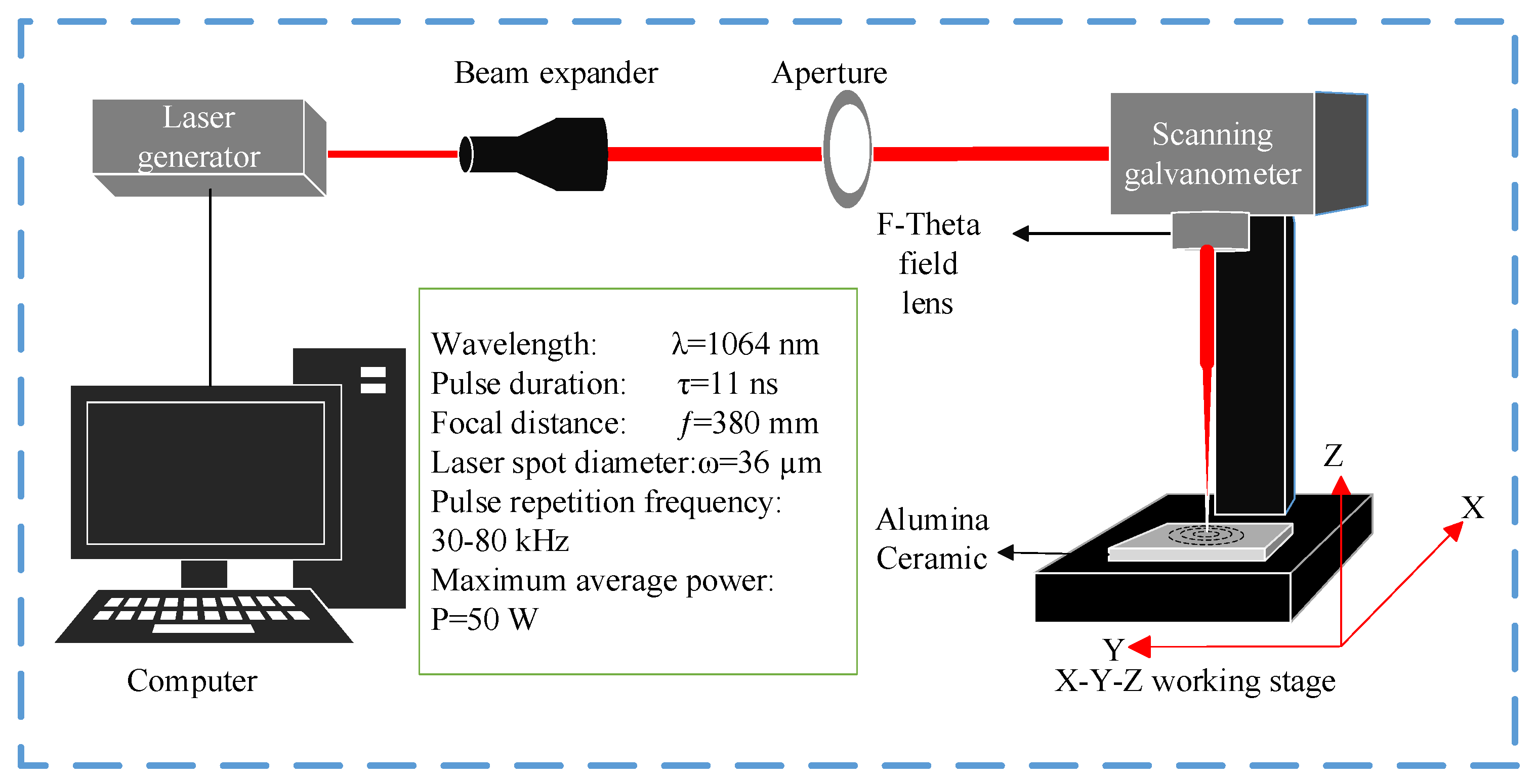
Figure 1 illustrates the schematic of a nanosecond pulse laser trepanning system, which includes the infrared nanosecond pulse laser (PEDB-400F, acquired from Wuhan Jiaxing Laser Ltd., Wuhan, China), the optical path transmission system, the dynamic focusing system, the control system, and the precise movement platform. The experiment employed a nanosecond laser with a wavelength of 1064 nm, which is capable of adjusting its pulse repetition frequency between 30 and 80 kHz. The laser spot diameter is approximately 36 µm, with a maximum average power of 50 W. The generated laser beam is transmitted through a beam expander and an optical aperture, before entering the scanning galvanometer system. It is then focused on the workpiece through a field mirror with a focal length of 380 mm. Once the laser beam has been focused through a field mirror with a focal length of 380 mm, it is applied to the workpiece, enabling the hole processing of the workpiece.
In this paper, nanosecond laser triple rings trepanning technology is selected for drilling, as illustrated in
Figure 2. The laser beam is focused on the top surface of the workpiece, with the innermost ring piercing the material in the center of the hole to form a prefabricated hole. The intermediate ring serves to widen the diameter of the hole, while the outermost ring modifies the shape of the hole. The workpiece is then repeatedly scanned along a circular path to achieve the desired processing. This procedure is repeated until the workpiece has been processed.
This study utilized triple rings laser trepanning technology to process holes in Al
2O
3 ceramics substrates, which were 0.25 mm thick. The effects of the number of laser scans, laser scanning speed, and the amount of defocusing on the geometrical features of the holes such as the hole diameter, hole roundness, and taper angle were studied. Four holes were processed under identical parameters. The maximum and minimum hole diameters at the entrance and exit of each hole are measured, respectively, as illustrated in
Figure 3. The average of the four maximum and minimum hole diameters is calculated as the maximum and minimum hole diameters under the parameter, respectively. The entrance and exit hole diameters of the hole can be calculated by Equation (1). The roundness of the hole can be calculated by Equation (2), where
R is defined as the roundness of the hole. The closer
R is to 1, the better the hole roundness is. The two equations contain the variables
Dmax and
Dmin, which represent the maximum and minimum hole diameters, respectively. As illustrated in
Figure 4, the Equation (3) can be employed to calculate the taper. This formula requires the following inputs:
Dent, which represents the diameter at the entrance of the hole,
Dext, which represents the diameter at the exit from the hole, and
h, which represents the thickness of the Al
2O
3 ceramics substrate.
The Al
2O
3 ceramics substrate selected for the experiment was of 96% purity with a size of 100 × 100 × 0.25 mm.
Table 1 presents some of the properties of the Al
2O
3 ceramics substrate. Prior to the commencement of the experiment, the samples were subjected to a 10 min cleaning process, which involved the use of a combination of ultrasound and anhydrous ethanol. Subsequently, the samples were placed on a precision moving table for processing. After that, the samples were subjected to ultrasonic cleaning and drying. The surface morphology and size of the holes were observed at the conclusion of the experiment using a confocal laser scanning microscope (Olympus OLS 4100, acquired from Olympus Corporation, Tokyo, Japan).
All experiments and measurements were performed at least four times for repeatability and reliability. The results were statistically analyzed by a one-way analysis of variance (ANOVA) test using Excel. A p value of <0.05 was considered statistically significant. The general standard error of the measurement ranged between 0% and 5%.
3. Results and Discussion
The effects of the number of laser scans (N), laser scanning speed (v), the amount of defocusing (f), and the laser power (P) on the geometrical features of the holes such as the hole diameter, hole roundness, and taper angle were studied and discussed in detail. A circle with a diameter of 300 µm was drawn using LenMark_3DS 5.2.3 software, and then the circle was filled with concentric circles. The remaining parameters were fixed during the experiments: the laser pulse duration was fixed at 11 ns, the laser average power was set at 30 W, the laser repetition frequency was set at 50 kHz, the hopping speed was set at 2000 mm/s, and the interval of the filled circle was set at 50 µm.
3.1. Effect of Number of Scans on Hole Diameter and Taper Angle
The laser scanning speed (
v) was set to 100 mm/s, the amount of defocusing (
f) was set to 0 mm, and the number of laser scans (
N) was conducted at 10, 20, 30, 40, 50, 100, 150, 200, 250, and 300 times, respectively. This was done to explore the effect of the number of laser scans on the diameter of the hole diameter and taper angle.
Figure 5 illustrates the graphs of the entrance of the holes captured by a confocal microscope at varying scanning times. It can be observed that with an increase in the number of laser scans, the laser beam penetrated deeper into the material, the entrance diameter of the holes gradually expanded, and concurrently, the entrance to the holes became increasingly circular with an increase in the number of laser scans. At 50 scans, the hole entrance diameter had reached its maximum saturation.
Figure 6 shows the variation in the average diameter of holes as a function of the number of laser scans. The results demonstrate that the average diameter at the entrance and exit of the holes showed a significant disparity. As the number of scans increased from 10 to 50, the diameters at the entrance and exit of the holes showed a notable and gradual increase. At 50 scans, the diameter of the hole showed a pronounced and abrupt increase compared to the previous value. However, following 50 scans, the average diameters at the entrance and exit of the holes hardly changed with the increase in the number of scans. This is due to the fact that when the number of scans was limited, the energy generated by the laser was insufficient to fully process the holes. As the number of scans increased gradually, the material absorbed more and more energy. At 50 scans, the diameter of the hole reached a saturated state, which was limited by the laser processing trajectory. After this point, as the number of scans increased, the holes diameter remained relatively unchanged. However, the average hole diameter at the entrance was significantly larger than the average hole size at the exit, which also resulted in all processed holes being tapered.
Figure 7 shows the variation in the average taper angle of holes as a function of the number of laser scans. The results indicate that the taper angle of the holes initially decreased with an increase in the number of laser scans. However, when the holes reached saturation, the holes taper angle hardly changed. The hole taper angle was 11.05° when the number of scans was 10; it is evident that the hole taper angle was considerable. This is due to the fact that when the number of scans was limited, the laser energy that reached the bottom of the hole area was relatively small, which hindered the laser from processing the holes area adequately. Consequently, the hole taper angle was considerable. With an increase in the number of laser scans, the energy absorbed in the processing area also increased, resulting in more thorough processing of the entrance and exit of the hole. Upon reaching a total of 50 scans, the hole taper decreased to 6.49°. Thereafter, with an increase in the number of laser scans, the hole taper remained almost unchanged.
Table 2 shows the roundness of the hole entrance and exit in the unsaturated state of the holes under varying laser scanning times.
Table 3 shows the roundness of the hole entrance and exit under varying laser scanning times at hole saturation. It can be seen that when the number of scanning times was less than 50, the roundness of the holes was significantly inferior to that of the holes after the hole diameter reaches saturation. This is attributed to the fact that the number of scanning times was smaller, the less laser energy was absorbed by the workpiece, resulting in a weaker laser’s ability to remove material. When the number of scans exceeded 50, the average roundness of both the entrance and exit of the hole structure exceeded 0.93. Notably, the entrance exhibits superior roundness compared to the exit. This is attributed to the fact that the entrance absorbed a greater quantity of laser energy.
3.2. Effect of Scanning Speed on Hole Diameter and Taper Angle
The number of laser scans (
N) was set to 300 times, the defocusing amount (
f) was set to 0 mm, and the laser scanning speed (
v) was conducted at 50 mm/s, 100 mm/s, 150 mm/s, 200 mm/s, and 250 mm/s, respectively. These parameters were chosen to examine the impact of the laser scanning speed on both the hole diameter and taper angle. Equation (4) [
30] can be used to calculate the spot overlap rate in the laser scanning direction, where
D(
E) is the diameter of the ablation zone of a single pulse, depending on the laser pulse energy (
E),
v is the scanning speed, and
f is the pulse repetition frequency.
The entrance and exit morphologies of the holes drilled using different laser scanning speeds are shown in
Figure 8. As is shown in
Figure 8, with an increase in the laser scanning speed, both the hole entrance and exit size decreased, and the decrease in the hole exit size was more significant. Also, some splash can be seen near the entrance to the hole. During laser machining, when the laser beam strikes the surface of the material, some part of the laser energy is lost due to the reflection and the remaining part of the energy is absorbed by the material. The application of laser irradiation to the surface of the material results in a gradual increase in temperature. Upon reaching the melting point of the material, the latter begins to melt and form a molten pool. Concurrently, a plasma explosion generates shock wave pressure, which causes the liquid in the molten pool and the outward spattering of the gasified material to solidify on the surface of the material. Thus, a pronounced surface topography is generated on the laser-interacted surface.
Figure 9 shows the variation in the average diameter of holes as a function of the laser scanning speed. The results indicate a significant disparity in the average diameter between the entrance and exit of holes, with both diameters tending to decrease to varying extents with an increase in the laser scanning speed. This phenomenon was attributed to the direct impact of the laser scanning speed on the pulse-overlap of the laser spot. An increased pulse-overlap not only boosted the laser energy deposited per unit area but also promoted a more continuous ablation process. An increased laser scanning speed reduced the overlap area of the laser beam and thus indirectly reduced the absorption of laser energy by the workpiece, especially at the bottom of the hole. Consequently, with an increase in the laser scanning speed, the laser’s ablation of the workpiece decreased and led to a reduction in the average diameter at both the entrance and exit to the hole.
Figure 10 shows the variation in the average taper angle of holes as a function of the laser scanning speed. It can be seen that the average taper angle of the holes increased with the increasing laser scanning speed. While the average diameter at the entrance to the hole remained relatively stable compared to the average diameter at the exit from the hole, the variance between entrance and exit diameters expanded with an increase in the laser scanning speed. Consequently, the average taper angle of the hole escalated. Notably, at a scanning speed of 50 mm/s, a hole with a 5.51° taper angle was achieved. The findings of this paper are more compelling than those of the study conducted by Zhang et al. [
24]. It can be inferred that lowering the laser scanning speed led to a smaller taper. However, excessively low speeds could compromise the efficiency of the hole processing.
Table 4 shows the roundness of the hole entrance and exit at different laser scanning speeds. The results indicate that both the entrance and exit exhibit roundness values exceeding 0.93, with the entrance showing a significantly higher roundness than the exit. This disparity was due to the entrance absorbing a larger amount of laser energy.
3.3. Effect of Defocusing Amount on Hole Size and Taper Angle
The number of laser scans (
N) was set to 50 times, the laser scanning speed (
v) was set to 100 mm/s, and the laser defocusing amount (
f) was conducted at −2 mm, −1 mm, 0 mm, 1 mm, and 2 mm, respectively. These parameters were chosen to examine the impact of the laser defocusing amount on the diameter and taper angle of the holes. In
Figure 11, ‘0’ represents the sample surface, with positive values (+) indicating positions above the surface and negative values (−) indicating positions below it.
The entrance and exit morphologies of the holes drilled using different forms of defocusing are shown in
Figure 12. As shown in
Figure 12, some splash can be seen near the entrance to the hole. It can be found that the average diameter of the entrance to the holes increases with the increasing laser defocusing amount, while the largest diameter at the exit occurs at the focus point. As previously stated, the laser interacts with the material, resulting in the generation of a high-temperature plasma. The plasma temperature subsequently reaches a constant value, undergoes an explosion, and impinges on the material surface at an exceedingly high velocity, thereby creating a shockwave pressure. The shock wave pressure causes liquid droplets in the melt pool, as well as vaporized material, to be splashed and deposited on the material surface. These deposits then form a pronounced surface topography after solidification.
Figure 13 shows the variation in the average diameter of holes as a function of the laser defocusing amount. It can be seen that the average diameter of the entrance to the holes increases with the increasing laser defocusing amount, while the largest diameter at the exit occurs at the focus point. As the laser defocusing amount was reduced, the laser beam waist radius decreased and the laser energy density increased. This resulted in enhanced laser ablation of the alumina ceramics. The laser energy density, denoted as
Ed, can be calculated using Equation (5), where
E represents the laser energy,
D is the spot diameter, and
v is the laser scanning speed. Consequently, with a decrease in the laser defocusing amount, the diameter of the holes became larger. The radius of the laser spot increased with the distance from the focal point in the positive defocused state. As the laser beam became less unfocused, the channel width increased [
31]. This resulted in an expansion of the ablation range of alumina ceramics, which in turn led to an increase in the diameter of the holes. The distance from the focal point at which this occurs was greater in the positive defocused state.
Figure 14 shows the variation in the average taper angle of holes as a function of the laser defocusing amount. It can be seen that the taper angle was minimized at a defocusing amount of 0 mm, corresponding to the focal point. It is widely acknowledged that the focal point’s position significantly influences the spot size on the sample surface, subsequently impacting the laser energy density, kerf width, and hole taper. The nature of the laser beam dictates that the energy is highest near the focal point and diminishes as the distance increases. In other words, when the specimens were placed at the focal length, the laser energy became concentrated around the focal point. The laser beam scattered as it was moving away from the focal point and the laser energy intensity became weaker [
32]. Consequently, the most effective ablation of the hole exit occurred at the focal point, resulting in the smallest taper angle. Based on the experimental parameters outlined in this study, processing the material at a 0 mm distance from the focal point is recommended to enhance the hole taper quality.
Table 5 shows the roundness of the hole entrance and exit at different laser defocusing levels. The results show that both the entrance and exit roundness values surpass 0.93, with the entrance displaying notably higher roundness than the exit. This difference is due to the increased absorption of laser energy at the hole entrance.
3.4. Effect of Laser Power on Hole
The number of laser scans (N) was set to 50 times, the laser scanning speed (v) was set to 100 mm/s, the laser defocusing amount (f) was set to 0 mm, and the laser power (P) was conducted at 10 W, 20 W, 30 W, 40 W, and 50 W, respectively. These parameters were chosen to examine the impact of laser power on the diameter and taper angle of the holes.
The entrance and exit morphologies of the holes drilled using different laser power are shown in
Figure 15. As shown in
Figure 15, at laser powers of 5 W and 10 W, the laser ablation process did not result in the formation of through-holes in the workpiece. This is attributable to the fact that the low laser power results in a reduction in the energy generated by the laser, which is insufficient to create a through-hole in the workpiece. At lower power settings, the reduction in intensity precludes the penetration of heat into the material to a greater depth and the intensity of the heat was insufficient to facilitate the removal of material [
32]. When the laser power is 30 W, the workpiece has formed a through-hole due to the laser ablation. It can be observed that the laser, with an increased laser power, has generated sufficient laser energy to facilitate the formation of a through-hole in the workpiece. It can be further observed that when the laser power is 40 W and 50 W, an excess of laser power results in the formation of spattering and microcracking at the hole exit. Accordingly, it is deemed appropriate to process the Al
2O
3 ceramics substrate at a power of 30 W.


 ,
, 


