Abstract
The accurate measurement of spindle errors, especially quasi-static errors, is one of the key issues for the analysis and compensation of machine tool thermal errors in machining accuracy. To quantitatively analyze the influence of the measurement system’s own drift on the measurement results, a drifted uncertainty evaluation method of the precision instrument considering the time drift coefficient is proposed. This study also produced a high-precision compact spindle error measurement device (with a displacement measurement error of less than ±1.33 μm and an angular measurement error of less than ±1.42 arcsecs) as the research object to verify the proposed drift uncertainty evaluation method. A method for evaluating the drift uncertainty of the measurement system is proposed to quantitatively evaluate the system error and drift uncertainty of the measurement device. Experiments show that the drift uncertainty evaluation method proposed in this paper is more suitable for evaluating the uncertainty changes in measurement instruments during long-term measurements compared to traditional methods.
1. Introduction
The mechanical accuracy of the spindle of a CNC machine tool is one of the decisive factors for the upper limit of the machining accuracy of the machine tool. The thermal error of the spindle seriously affects its mechanical accuracy. How to measure and analyze the spindle error of the machine tool and separate and evaluate its thermal error are of great significance and economic value in improving the quality of the machine tool, which directly affects the modeling accuracy and robustness of thermal error analysis.
The measurement methods for spindle errors are usually divided into contact and non-contact. Liu proposes a five-degrees-of-freedom measurement system for measuring the geometric errors of the rotary axis [1]. Zhao presents a measurement system for the simultaneous measurement of geometric errors in six degrees of freedom (DOF) [2]. Jia presented a method for the simultaneous measurement of five-degrees-of-freedom spindle error motions in computer numerical control (CNC) machine tools and developed a measurement system [3]. Hong proposed a two-axis planar encoder optical structure for measuring the error of the spindle in the X and Z directions [4]. Elie used a non-contact R-Test on a five-axis machine tool to measure the spatial thermal error caused by the motion of the rotation axis. The measuring device has four workpieces and a reference ruler with uncalibrated standard balls. The error of the standard ball position and the rotation axis are evaluated by the collected volume data [5]. Murakami developed an optical measurement system to simultaneously measure the five-degrees-of-freedom error of a high-speed spindle. The measurement error caused by a lens error was analyzed by the ray tracing method [6]. Madden developed a set of phase modulation interferometers with three Michelson interferometers and three grating interferometers. The thermal errors of the radial, axial, and two-dimensional angles of the spindle are measured synchronously by concentric circular gratings and phase modulation interferometers [7]. Jia proposed a simultaneous measurement of five-DOF spindle error motions of machine tools and developed a measurement system [3]. Zhang used a single sensor system to simultaneously measure vibrations in both the vertical directions of the tool tip [8]. Liu identifies and separates multiple dynamic and quasi-static errors simultaneously, using the actual cutting of a stepped workpiece as the error source [9]. Ibaraki designed a non-contact laser barrier tool measurement system that measures rotary axis positioning errors while the spindle is running [10]. Ni proposed a measurement method based on a composite laser target to simultaneously measure the motion error of the spindle at five degrees of freedom [11].
The current measurement uncertainty evaluation guidelines and related specifications are mainly for static calibration and static measurement. Many scholars in different fields have proposed various evaluation methods and theories based on standard specification documents and actual measurement scenarios. Bartel presents a Monte Carlo uncertainty assessment of the error in the regression of variables and derives the measurement function and its uncertainty assessment for calibrated force measurements [12]. Motra introduced a method for the qualitative assessment of experimental results based on Monte Carlo methods [13]. Michael proposed the uncertainty evaluation theory of in situ measurement to avoid the influence of sampling uncertainty without removing physical samples [14]. Deng analyzed the nature and effective evaluation method of the Shannon entropy as a measurement uncertainty, and discussed the challenges faced by the Shannon entropy in applications [15]. Silva proposed and validated a generalized method for assessing the uncertainty of time-varying measurements by fitting a model, resampling, and refitting to estimate the uncertainty for each data point [16]. Jakob developed an accurate stepper meter calibration system to analyze room temperature and oscillation-induced thermal expansion and measurement errors, and modeled the measurement uncertainty [17]. Wang analyzed the effects of measuring instruments and experimental protocols on subjective measurement uncertainty, examining four widely used subjective metrics: heat sensation, humidity sensation, dryness sensation, and heat satisfaction [18]. Jared suggests that measurement errors may be biased toward falsely rejecting the true null hypothesis, and that regression models with high-dimensional fixed effects exacerbate measurement error bias and increase the likelihood of false positives [19]. Zhang proposed a method for the thermal error modeling of CNC machine tool spindle units and machining accuracy reliability analysis [20].
However, the evaluation of dynamic measurement uncertainty is still an open research topic and has not yet formed a universal theoretical system. This has also made it difficult to separate the instrument’s own drift error from the measurement results and assess the impact of changes in the instrument’s long-term measurement uncertainty on the measurement results of quasi-static errors, such as spindle thermal errors. Existing measurement uncertainty evaluation methods can only assess the uncertainty of multiple data acquisitions within a short period of time and a single independent measurement, but cannot describe the non-repetitive characteristics of quasi-static errors, such as thermal errors, in multiple independent measurements.
To address this issue, this paper proposes an evaluation method for the drift uncertainty of measurement systems and validates its effectiveness using a developed compact spindle error measurement device as the subject. Firstly, the measurement principle of the instrument and the evaluation results of its measurement accuracy are introduced. Secondly, a detailed definition and evaluation method for drift uncertainty are proposed. Finally, based on a series of verification experiments, the correctness and effectiveness of the proposed drift uncertainty evaluation method are demonstrated, showing that the evaluated drift uncertainty in this paper can effectively assess the characteristics of the instrument’s measurement uncertainty changing with time.
2. Measurement Principle
2.1. Definition of Spindle Error Motion and Design of the Measurement System
During machine tool machining, the workpiece is usually fixed on the table with a fixture, while the tool is driven by the spindle for machining. As shown in Figure 1, thermal drift of the spindle in the X, Y, and Z directions leads to deviations in the machining position of the workpiece, thus affecting the dimensional accuracy and surface quality of the machined part. At the same time, the thermal tilt of the spindle around the X-axis and Y-axis leads to the deviation of the tool and the position of the tip point, which affects the contour accuracy and surface quality of the machined parts.
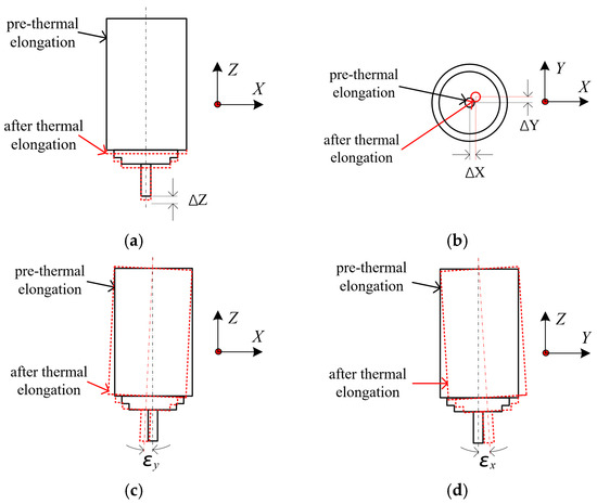
Figure 1.
Error terms of the machine tool spindle: (a) Axial thermal elongation of the spindle, (b) Radial thermal drift of the spindle, (c) Yaw angle error of the spindle, and (d) Pitch angle error of the spindle.
The measurement principle and overall structure of the measurement system proposed in this paper are shown in Figure 2. The displacement error of the spindle in the XYZ direction is measured by the laser triangle reflection displacement sensor relative to the surface of the precision ball, and the change in the ball center coordinates is calculated. The tilt error around the X-axis and Y-axis is measured by an autocollimator. During the measurement, the fixed part is installed on the workbench of the machine tool, and the target is installed on the measured spindle.
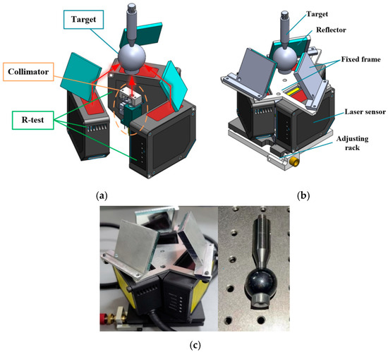
Figure 2.
Measurement principle and prototype: (a) measurement principle, (b) model of prototype, and (c) photo of the prototype.
2.2. Displacement Measurement Principle
The spindle thermal drift error is measured based on the principle of laser triangulation, and the spatial position of the standard ball is measured by using mirrors oriented to change the projection direction of the laser beam. Its structure and measurement principle are shown in Figure 3a, including three non-contact laser displacement sensors (LDSs), the laser beam emitted from the laser diode (LD) collimated by the emitting lens (EL), three optical mirrors, and a standard ball evenly distributed. The actual measurement optical path of the laser displacement sensor and the equivalent measurement optical path are shown in Figure 3b, and the displacement value can be calculated according to Equation (1). According to the measured three displacement values, the standard ball center coordinates in the measurement coordinate system can be obtained by calculating the solution, and the measurement coordinate system is shown in Figure 3c. The laser beam of the laser displacement sensor is reflected by the mirror and shines on the target ball’s surface. The receiving lens gathers part of the diffusely reflected beam and focuses it on the photosensitive element. When the target surface produces a displacement, the position of the light spot on the linear array also changes, with the relationship described as follows:
d is the distance from the imaging focusing lens to the optical axis of the sensor, f is the focal length of the receiving lens (RL), and x is the deviation displacement of the spot on the CCD photosensitive unit.
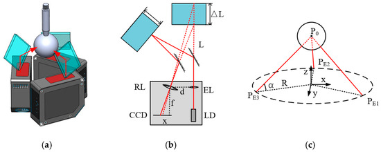
Figure 3.
Displacement error measurement principle: (a) design, (b) displacement measurement principle, and (c) ball center displacement calculation.
When the position of the precision ball at the measurement end changes, the three-dimensional displacement (x, y, z) of the spindle can be obtained by calculating the distances, L, from the three laser sensors:
where ai, bi and ci are the transformation coefficients to be calibrated of the displacement–coordinate transformation matrix; (x0, y0, z0) is the initial position of the standard ball; and L1, L2, and L3 are the displacement values measured by the three sensors.
2.3. Tilt Measurement Principle
The spindle tilt measurement adopts the autocollimation principle for measurement, and the measurement principle is shown in Figure 4. Combined with the polarizing beam splitter (PBS), quarter-wave plate (QWP), and reflector (M1), a measurement optical path is formed. The P polarized light reflected by the fixed reflector (M2) at the target end passes through the PBS and focuses on the four-quadrant detector (QPD). The relationship between the angular errors εx and εy of the spindle and the position change in the focused spot on the QPD is as follows:
where εx represents the pitch error, εy represents the yaw error, Δy and Δx are the corresponding spot offsets on the QPD, and f is the focal length of the focusing lens (FL).
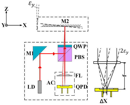
Figure 4.
Principle of the tilt error measurement.
3. Definition and Evaluation of Drift Uncertainty
3.1. Definition of Drift Uncertainty
There are already relevant standards for evaluating instrument measurement uncertainty [21], but in the context of the long-term drift measurement of geometric errors, data obtained from multiple repeated measurements under the same conditions tend to drift over time, often resulting in increasing dispersion. The final measurement results are affected by the coupling of the instrument’s own drift and the drift of the measured equipment’s errors, leading to inaccuracies in the measured systematic errors and a significant overestimation of the evaluated measurement uncertainty. The existing methods for evaluating measurement uncertainty are not suitable for addressing this issue. In this paper, referring to the basic statistical principles of measurement uncertainty evaluation and incorporating time factors, we propose an evaluation method suitable for the long-term measurement uncertainty of instruments.
3.2. Evaluation Method of Drift Uncertainty
The definition and evaluation method for measurement equipment drift uncertainty are shown in Figure 5. Under the same experimental conditions, N repeated independent tests are conducted on the long-term drift of the instrument, and the probability distribution of the drift curve is depicted. The drift curve of the instrument comprises drift systematic errors and drift residuals. The drift systematic error represents the average value of the long-term drift curve obtained from N drift tests, which varies with time. After subtracting the drift systematic error, the residual drift curve is obtained, and its residual distribution increases with time. This means that the magnitude of the drift uncertainty and the confidence interval of the measuring instrument are correlated with the time variable.
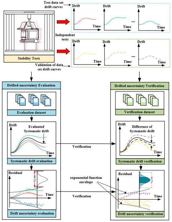
Figure 5.
Evaluation and verification process for measurement equipment drift uncertainty.
The process of the drift uncertainty evaluation for an instrument involves several steps. Initially, it is crucial to measure and compute the short-term repeatability of the machine tool:
where P0 represents the short-term repeatability, ei denotes the drifted error observed independently in the i-th group within a short period of time under the same operating conditions. After conducting a series of independent drift tests, the systematic drift can be distinguished as follows:
where SE(j) represents the systematic drift and ei,j denotes the j-th measured drift obtained from the i-th independent observation under the same operating conditions. The drift uncertainty of the residual errors derived from each independent measurement is as follows:
where Ps is the expression function of the drift uncertainty envelope line. The drift coefficient, s, is determined by an optimization algorithm, specifically calculated to ensure that the probability of the residuals falling within the positive and negative 2Ps envelope lines is 95%. In this paper, the downhill method is utilized as the search method for obtaining this coefficient. The drift uncertainty with 95% and 99.7% confidence levels could be obtained as follows:
4. Verification of Drift Uncertainty Evaluation
4.1. Experiment Design
To verify the correctness of the evaluation method for measurement equipment drift uncertainty proposed in this paper, a measurement equipment drift test rig, as shown in Figure 6, was constructed. The base of the test rig adopts a vibration-isolated optical platform to avoid adverse effects on equipment readings caused by vibrations and external shocks. The structural components of the test rig and the vibration-isolated optical platform are made of materials with consistent thermal expansion coefficients and are symmetrically designed to avoid changes in readings caused by the deformation of the structure itself. The testing process is conducted in a constant-temperature laboratory with controlled ambient temperature (20 ± 1 °C), and the ambient temperature is monitored during the experiment to avoid and compensate for the impact of structural thermal deformation on the readings.
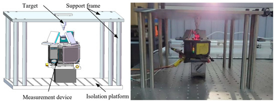
Figure 6.
Stability test design.
4.2. Evaluation and Verification Results
By calculating the test data samples and confidence intervals, the drift coefficient, s, of the measured physical quantity is determined, and the evaluation of the drift uncertainty of the validation data samples is conducted to obtain the drift standard deviation envelope functions in five degrees of freedom. As shown in Figure 7 and Table 1:
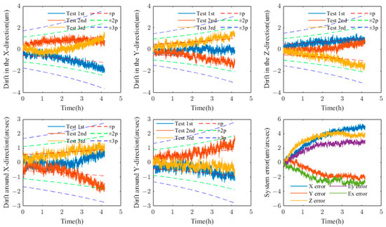
Figure 7.
Test set data.

Table 1.
Test set long-term drift uncertainty index.
According to the long-term precision correctness test method proposed in this paper, the confidence uncertainty of each error term at the values of ±p, ±2p, and ±3p is calculated. The drift uncertainty evaluation results are as follows.
Based on the experimental data and results, it can be observed that, within 4 h, as shown in Figure 8, the detection results of the drift data from the validation sets of various measurement systems basically align with the drift precision distribution model presupposed in this paper in terms of probability. The specific results of the probability distribution test are presented in Table 2. It can be seen from the results that the evaluation error of the drift precision proposed in this paper does not exceed 10%, which is significantly lower than that of traditional measurement uncertainty evaluation models. Furthermore, the probability distribution within each confidence interval meets the testing conditions, indicating that the stability and drift uncertainty of the measurement system can meet the usage requirements.
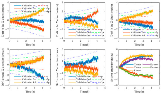
Figure 8.
Verification of the evaluation results of the dataset.

Table 2.
Validation set long-term drift uncertainty evaluation results.
5. Performance Test
To verify the measurement accuracy and repeatability of the measurement system proposed in this paper, and to evaluate its drift characteristics using the method proposed here, a series of experiments were conducted. The details follow.
5.1. Calibration
The calibration of the laser displacement sensor after installing the reflected optical path is performed using a high-precision micrometer (type 805-5506, SYLVAC) as the reference. The calibration mechanism design is shown in Figure 9a, with a calibration stroke of 10 mm. The measurement accuracy of the tilt angle is calibrated using a multi-degree-of-freedom laser interferometer (XM-60, Renishaw, with an angular measurement accuracy of ±1 arcsec) as the reference. The design of the calibration mechanism is shown in Figure 9b, with a calibration stroke of ±100 arcsecs. The final calibration results are shown in Figure 10. The calibration results indicate that, within the 10 mm measurement range of the sensor, by comparing this with the angles measured by a dial indicator or a laser interferometer, the residual error is obtained. The calibration residuals of the laser displacement sensor are all ±3 μm or under within 200 arcsecs and the calibration residuals of the tilt angle measurement are within 1.5 arcsecs, both meeting the high-precision error measurement requirements of the spindle.
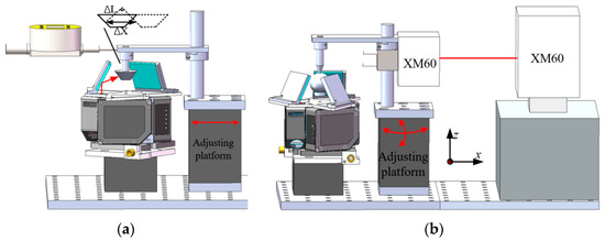
Figure 9.
Calibration experiment setup: (a) accuracy calibration of the laser displacement sensor and (b) accuracy calibration of the tilt angle measurement.
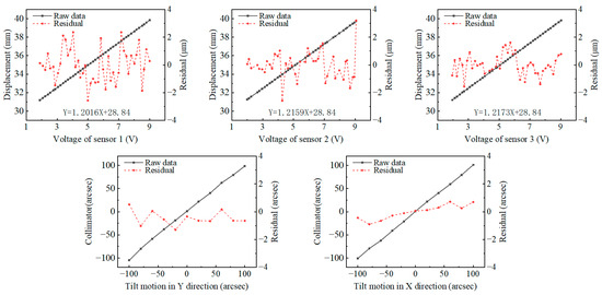
Figure 10.
Calibration results.
5.2. Performance Test of Ball Center Position Calculation
The calibration of three-dimensional displacement is performed on a precisely error-compensated CNC machine tool (HMC400 Pro, HIMILE, ±3 μm/500 mm after compensation) using the high-precision micro-movement of the machine’s linear axes. Based on the actual coordinates of the machine tool, calibration is carried out within ±100 μm in the XYZ directions, with a step size of 20 μm. The calibration setup is shown in Figure 11, and the calibration results are presented in Figure 12. The results indicate, that within the ±100 μm measurement range of the instrument, the calibration residuals for the XYZ coordinates are all within 2 μm. Using the precisely calibrated coordinate movement of the CNC machine tool as a reference, the readings from the instrument developed in this paper are subtracted to obtain the residual error.
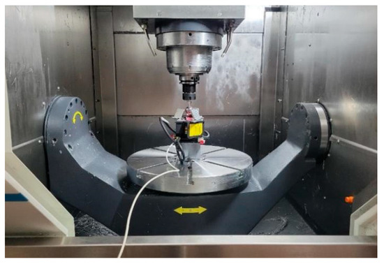
Figure 11.
Test setup for the three-dimensional displacement calculation accuracy.

Figure 12.
Comparison results of the three-dimensional displacement measurement accuracy.
5.3. Performance of Spindle Geometric Error Measurement Repeatability and Accuracy
To evaluate the measurement repeatability and accuracy of the measurement system, three repeated measurements were conducted on the spindle of the experimental machine tool using both the measurement system prototype and the spindle error measurement method based on ISO 230-7 [22]. The measurement results were used to assess the accuracy and repeatability of the measurement system prototype, with the experimental assumptions shown in Figure 13. During the measurement process, the same adjustable tool holder was used to clamp the measurement bar and target to avoid eccentricity and tilt errors caused by the installation of the tool holder and spindle.
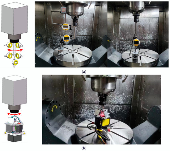
Figure 13.
Performance test: (a) method based on ISO230-7 and (b) proposed instrument.
As shown in Figure 14, the measurement and comparison results demonstrate that the measurement repeatability of the engineering prototype proposed in this paper is consistent with the error values obtained using commercial gauges based on the ISO 230-7 measurement method, between 0.3 μm and 0.5 arcsecs. The average value of the spindle rotation error readings measured by the measurement system developed in this paper is subtracted from the average value of the error readings measured based on ISO standards to obtain the residual error. The comparison residuals for measured displacement errors are within ±1.33 μm, and the comparison residuals for inclination angle errors are within ±1.42 arcsecs, satisfying the requirements for precision machine tool spindle error measurements. In terms of measurement efficiency and setup convenience, the prototype designed in this paper has clear advantages.
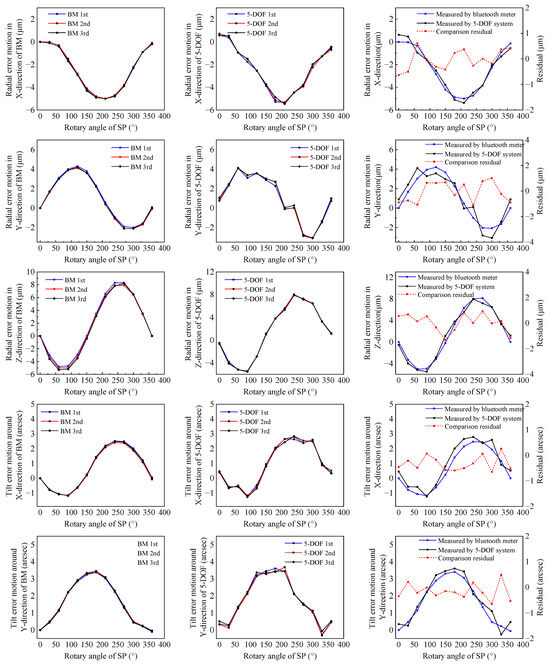
Figure 14.
Comparison results of spindle measurement errors.
5.4. Spindle Thermal Error Measurement
Using the spindle error testing system proposed in this article, we conducted a test on the 5-DOF (degree of freedom) thermal error of the spindle of an experimental machine tool. The experimental conditions consisted of a 3 h spindle working phase followed by a 1 h spindle cool down phase. During the experiment, the spindle of the test machine tool was first allowed to rotate continuously at a speed of 8000 rpm for 3 h to heat up the machine tool. After that, the spindle of the machine tool was allowed to stop rotating and the machine tool was allowed to cool naturally. During the experiment, the measuring target rotated along with the spindle, and spindle thermal error data were collected every 5 min. To eliminate the influence of spindle dynamic errors on the thermal error measurement results, the spindle thermal error test data were averaged over cycles that were integer multiples of the spindle speed. The measurement results of the tested machine tool’s thermal errors are shown in Figure 15.
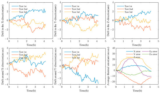
Figure 15.
Measurement results of spindle thermal errors.
From the experimental results, it can be seen that, after deducting the average value of the thermal error measurement data of the machine tool, the residual errors of the three measurements are slightly larger than the drift uncertainty of the instrument evaluated in the previous stage. This is because they include the uncertainty of the thermal characteristics of the machine tool itself, which will also be one of the key issues in our subsequent research.
6. Conclusions
This paper proposes an evaluation method for the drift uncertainty of measurement equipment based on the principles of probability analysis in traditional measurement uncertainty, incorporating the time factor. This approach aims to address the limitation of traditional measurement uncertainty evaluation methods, which are not suitable for quantitatively analyzing the phenomena of measurement equipment readings drifting and diverging over time. Using a self-developed compact spindle geometric error measurement system with a measurement accuracy of 1.5 μm/1.5 arcsecs as the analysis object, an experimental platform for the drift characteristics of the spindle measurement device was established and tested for validation. The experimental results show that, based on the test set and verification set data under the same experimental conditions, the drift uncertainty evaluation method proposed in this paper is more accurate at confidence levels of 68.26%, 95%, and 99.7% according to the normal distribution test, compared to traditional measurement uncertainty evaluation methods. It is more suitable for quantitatively evaluating the drift characteristics of measurement equipment readings.
The drift precision evaluation method proposed in this paper can be used for the quantitative assessment of the drift characteristics of instruments and equipment, providing a foundation for optimizing the drift characteristics of instruments and equipment, or analyzing the drift characteristics of the measurement objects of the instruments. Based on this foundation, future research will focus more on optimizing the drift characteristics of measurement equipment and quantitatively separating the drift characteristics of the measurement equipment from the drift readings of the measured object. This will enable a more accurate description of the quasi-static error variation characteristics of precision machinery, such as the drift characteristics of spindle geometric errors caused by thermal errors in machine tools.
Author Contributions
Conceptualization, Y.H.; Methodology, Y.H.; Software, X.Z.; Validation, X.Z.; Formal analysis, X.Z.; Investigation, Y.H.; Resources, J.C., H.Z. and H.X.; Data curation, X.Z. and K.Y.; Writing—original draft, Y.H., X.Z. and K.Y.; Writing—review & editing, Y.H.; Supervision, J.C., H.Z. and H.X.; Project administration, J.C.; Funding acquisition, J.C. All authors have read and agreed to the published version of the manuscript.
Funding
This research was funded by Research on digital intelligent reference model and evaluation index system of measurement and control equipment (2022YFF0605201).
Data Availability Statement
The datasets generated and analyzed during the current study are available from the corresponding author on reasonable request.
Conflicts of Interest
The authors declare no conflict of interest.
References
- Liu, L.; Lou, Z.-F.; Huang, Y.-B.; Fan, K.-C.; Zhang, J.-Y. A five degrees-of-freedom errors measurement system for rotary axis with reference laser for reference axis alignment. Rev. Sci. Instrum. 2020, 91, 075101. [Google Scholar] [CrossRef]
- Zhao, Y.; Zhang, B.; Feng, Q. Measurement system and model for simultaneously measuring 6DOF geometric errors. Opt. Express 2017, 25, 20993–21007. [Google Scholar] [CrossRef]
- Jia, P.; Li, P.; Zheng, F.; Feng, Q.; Zhang, B. Simultaneous measurement of 5DOF spindle error motions in CNC machine tools. Appl. Opt. 2022, 61, 5704–5713. [Google Scholar] [CrossRef]
- Hong, Y.; Sato, R.; Shimizu, Y.; Matsukuma, H.; Gao, W. A New Optical Configuration for the Surface Encoder with an Expanded Z-Directional Measuring Range. Sensors 2022, 22, 3010. [Google Scholar] [CrossRef] [PubMed]
- Bitar-Nehme, E.; Mayer, J. Modelling and compensation of dominant thermally induced geometric errors using rotary axes’ power consumption. CIRP Ann.-Manuf. Technol. 2018, 67, 547–550. [Google Scholar] [CrossRef]
- Murakami, H.; Katsuki, A.; Sajima, T. Simple and simultaneous measurement of five-degrees-of-freedom error motions of high-speed microspindle: Error analysis. Precis. Eng. 2014, 38, 249–256. [Google Scholar] [CrossRef]
- Madden, M.; Aketagawa, M.; Kumagai, T.; Maeda, Y.; Okuyama, E. Concurrent measurement method of spindle radial, axial and angular motions using concentric circle grating and phase modulation interferometers. Meas. Sci. Technol. 2014, 25, 094005. [Google Scholar] [CrossRef]
- Zhang, H.; Anders, D.; Löser, M.; Ihlenfeldt, S.; Czarske, J.; Kuschmierz, R. Non-contact, bi-directional tool tip vibration measurement in CNC milling machines with a single optical sensor. Mech. Syst. Signal Process. 2020, 139, 106647. [Google Scholar] [CrossRef]
- Liu, C.; Xiang, S.; Lu, C.; Wu, C.; Du, Z.; Yang, J. Dynamic and static error identification and separation method for three-axis CNC machine tools based on feature workpiece cutting. Int. J. Adv. Manuf. Technol. 2020, 107 (Suppl. S12–S13), 2227–2238. [Google Scholar] [CrossRef]
- Ibaraki, S.; Yanai, E. Identification of rotary axis location errors under spindle rotation by using a laser barrier tool measurement system—Experimental comparison with R-test. Trans. Inst. Syst. Control. Inf. Eng. 2021, 34, 81–88. [Google Scholar]
- Ni, H.; Zhao, W.; Qiu, L. Measurement method of spindle motion error based on composite laser target. Int. J. Mach. Tools Manuf. 2022, 174, 103860. [Google Scholar] [CrossRef]
- Bartel, T.; Stoudt, S.; Possolo, A. Force calibration using errors-in-variables regression and Monte Carlo uncertainty evaluation. Metrologia 2016, 53, 965–980. [Google Scholar] [CrossRef]
- Motra, H.; Hildebrand, J.; Wuttke, F. The Monte Carlo Method for evaluating measurement uncertainty: Application for determining the properties of materials. Probabilistic Eng. Mech. 2016, 45, 220–228. [Google Scholar] [CrossRef]
- Ramsey, H.M. Challenges for the estimation of uncertainty of measurements made in situ. Accredit. Qual. Assur. 2021, 26, 183–192. [Google Scholar] [CrossRef]
- Deng, Y. Uncertainty measure in evidence theory. Sci. China Inf. Sci. 2020, 63, 210201. [Google Scholar] [CrossRef]
- Silva, M.A.; Amado, C.; Ribeiro, Á.; Loureiro, D. Uncertainty evaluation in time-dependent measurements. Measurement 2022, 196, 111196. [Google Scholar] [CrossRef]
- Šafarič, J.; Dolšak, B.; Ačko, B. Analysis of thermal contribution to the measurement uncertainty in step gauge calibration. Precis. Eng. 2020, 66, 52–61. [Google Scholar] [CrossRef]
- Wang, J.; Wang, Z.; de Dear, R.; Luo, M.; Ghahramani, A.; Lin, B. The uncertainty of subjective thermal comfort measurement. Energy Build. 2018, 181, 38–49. [Google Scholar] [CrossRef]
- Jennings, J.; Kim, J.M.; Lee, J.; Taylor, D. Measurement error, fixed effects, and false positives in accounting research. Rev. Account. Stud. 2024, 29, 959–995. [Google Scholar] [CrossRef]
- Zhang, Z.; Feng, S.; Ding, Y.; Mei, X.; Tao, Z. Thermal error modeling of spindle and dynamic machining accuracy reliability analysis of CNC machine tools based on IA and LHSMC. Eksploat. Niezawodn. 2022, 24, 100–113. [Google Scholar] [CrossRef]
- JJF 1059.1-2012; Evaluation and Expression of Uncertainty in Measurement. General Administration of Quality Supervision, Inspection and Quarantine: Beijing, China, 2012.
- ISO 230-7; Test Code for Machine Tools-Part 7: Geometric Accuracy of Axes of Rotation. ISO: Geneva, Switzerland, 2011.
Disclaimer/Publisher’s Note: The statements, opinions and data contained in all publications are solely those of the individual author(s) and contributor(s) and not of MDPI and/or the editor(s). MDPI and/or the editor(s) disclaim responsibility for any injury to people or property resulting from any ideas, methods, instructions or products referred to in the content. |
© 2024 by the authors. Licensee MDPI, Basel, Switzerland. This article is an open access article distributed under the terms and conditions of the Creative Commons Attribution (CC BY) license (https://creativecommons.org/licenses/by/4.0/).