Author Contributions
Conceptualization, T.F.M. and H.E.-H.; methodology, T.F.M.; software, A.F.; validation, I.A.H., A.F. and D.-E.A.M.; formal analysis, M.G.A.N.; investigation, T.F.M.; resources, H.E.-H.; data curation, T.F.M.; writing—original draft preparation, T.F.M. and A.F.; writing—review and editing, M.G.A.N.; visualization, T.F.M.; supervision, T.F.M.; project administration, E.A.G.; funding acquisition, H.E.-H. All authors have read and agreed to the published version of the manuscript.
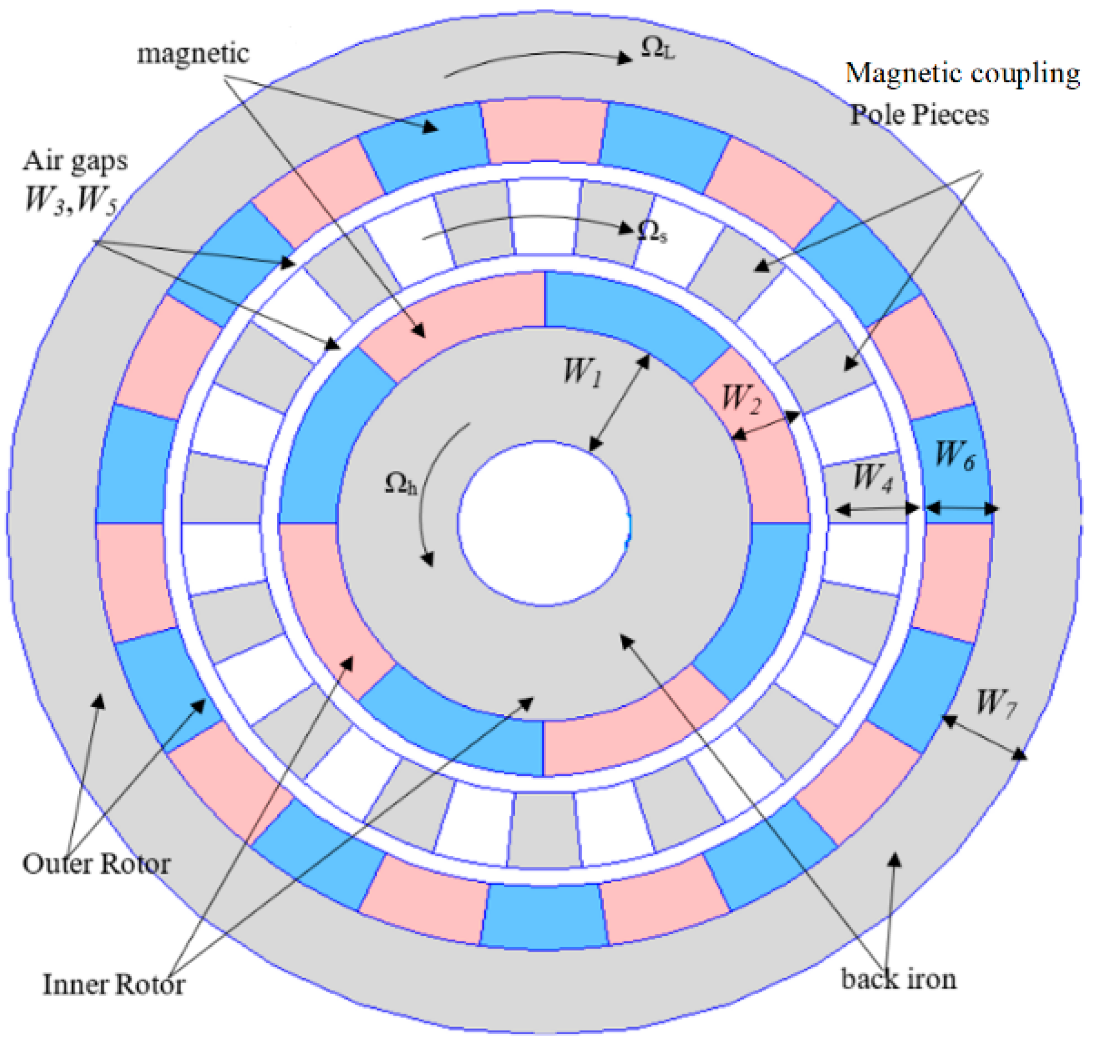
Figure 1.
Conventional magnetic gear.
Figure 1.
Conventional magnetic gear.
Figure 2.
Flowchart showing the steps for designing the optimal thickness of the magnetic gear elements.
Figure 2.
Flowchart showing the steps for designing the optimal thickness of the magnetic gear elements.
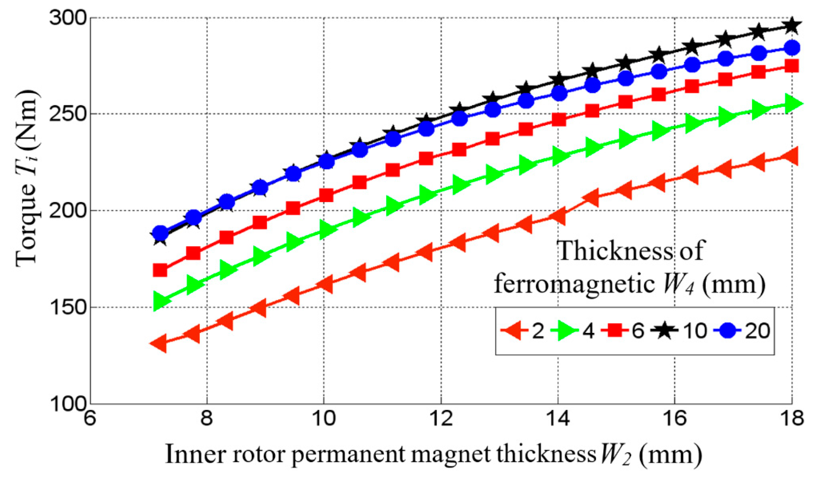
Figure 3.
Relationship between inner rotor torque Ti and inner rotor magnet thickness.
Figure 3.
Relationship between inner rotor torque Ti and inner rotor magnet thickness.
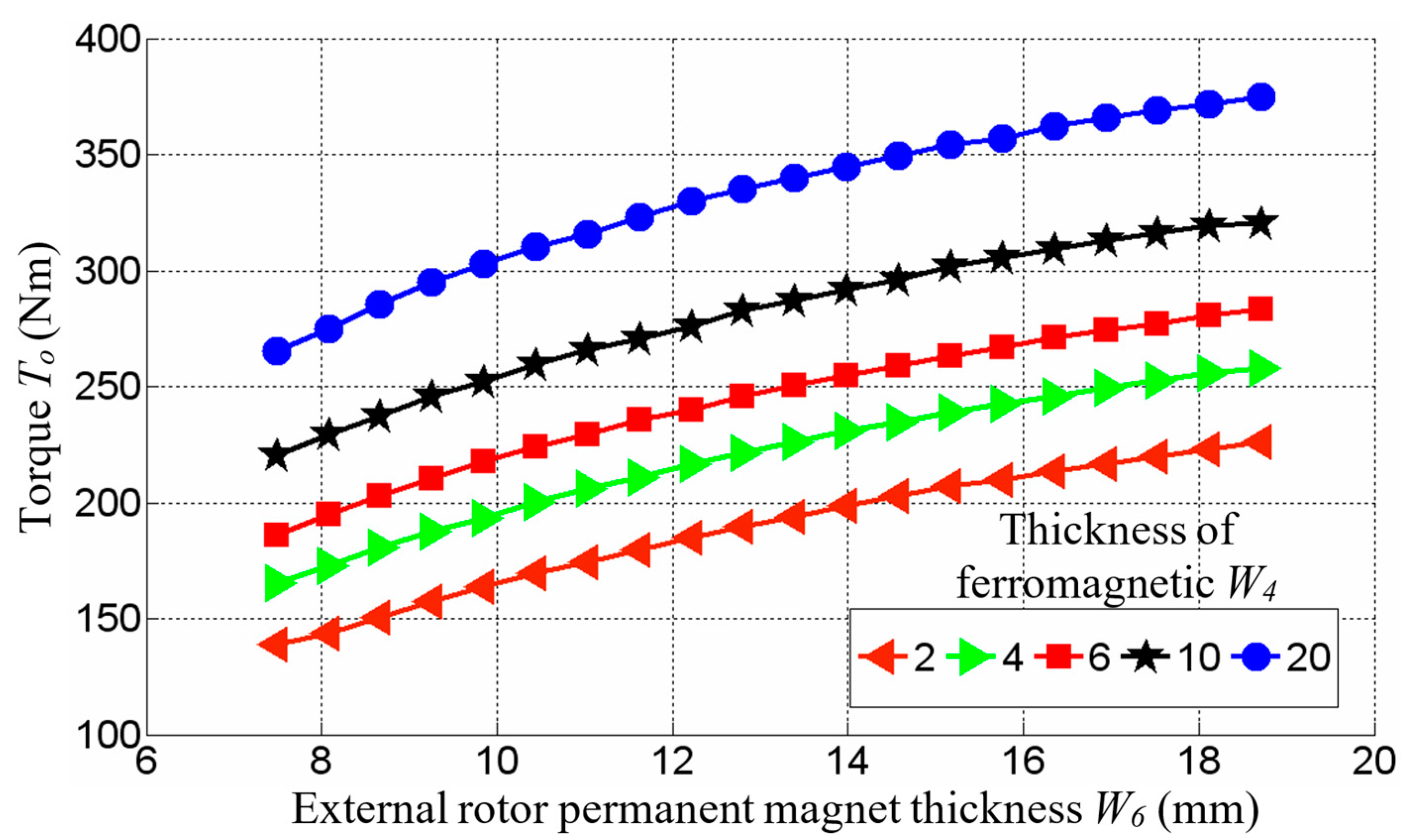
Figure 4.
Relationship between outer rotor torque To and outer rotor magnet thickness.
Figure 4.
Relationship between outer rotor torque To and outer rotor magnet thickness.
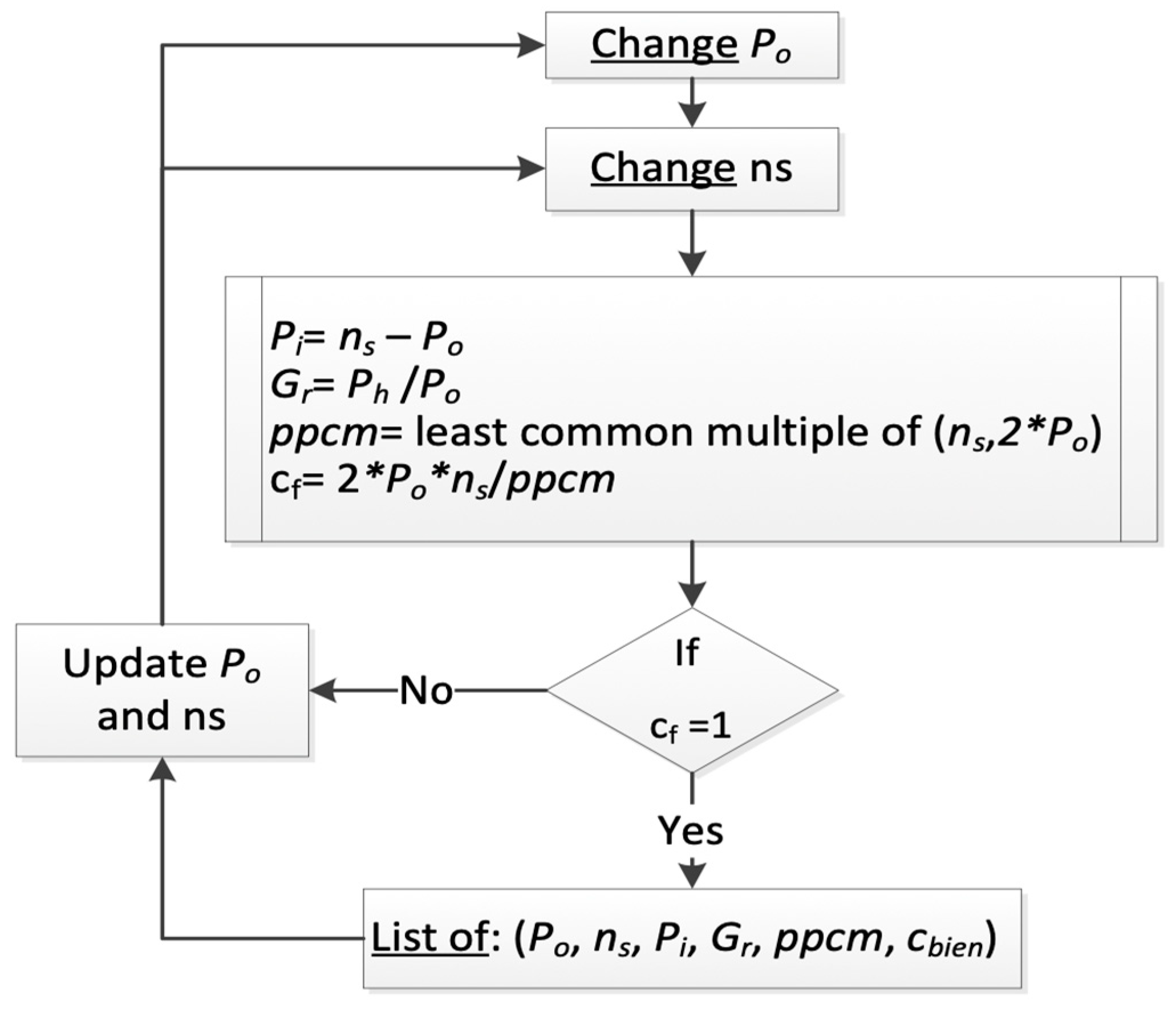
Figure 5.
Flowchart showing the steps for choosing a list of torque ratios Gr that gives the lowest torque ripples.
Figure 5.
Flowchart showing the steps for choosing a list of torque ratios Gr that gives the lowest torque ripples.
Figure 6.
Proposed magnetic gear using coils instead of permanent magnets.
Figure 6.
Proposed magnetic gear using coils instead of permanent magnets.
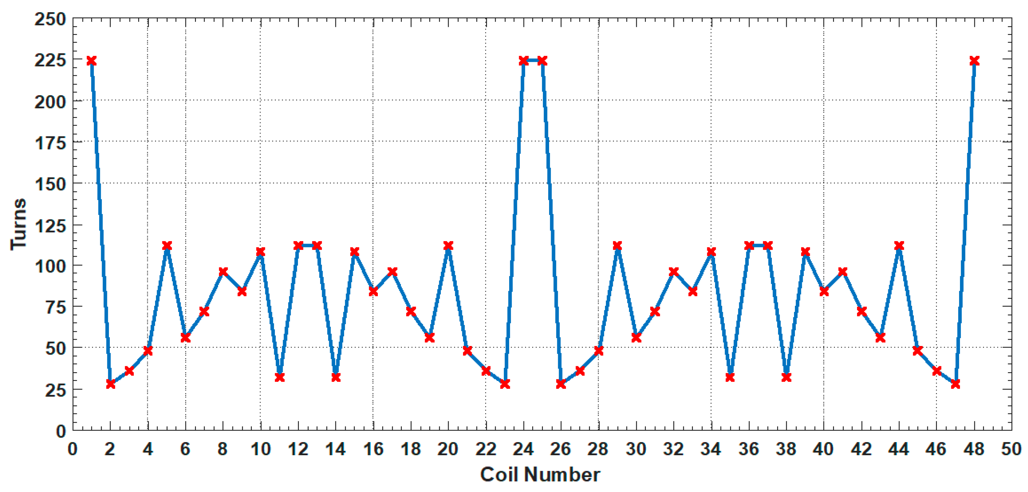
Figure 7.
Number of turns for each inner rotor coil number in Gr1.
Figure 7.
Number of turns for each inner rotor coil number in Gr1.
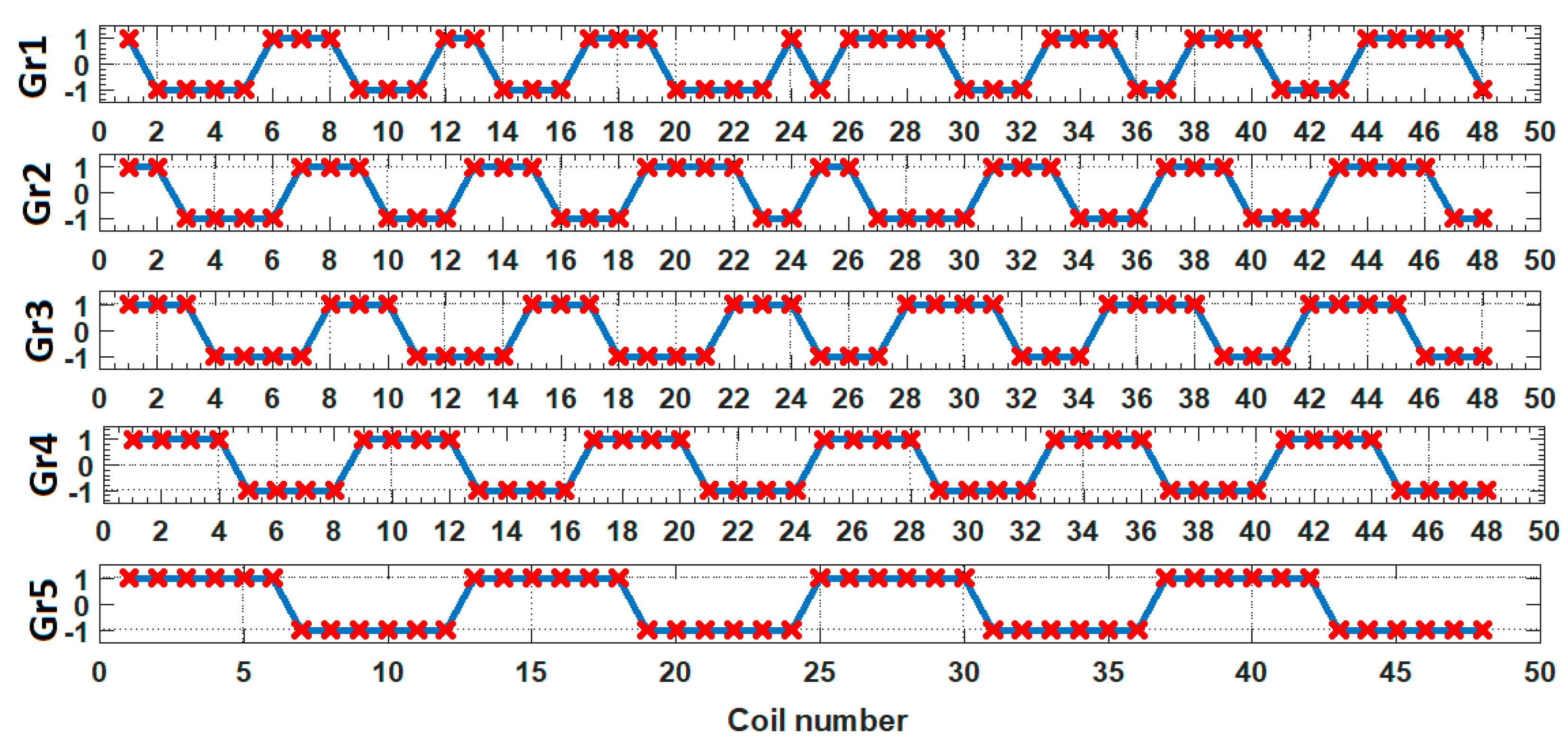
Figure 8.
Inner rotor control signals for the coils for each gear ratio.
Figure 8.
Inner rotor control signals for the coils for each gear ratio.
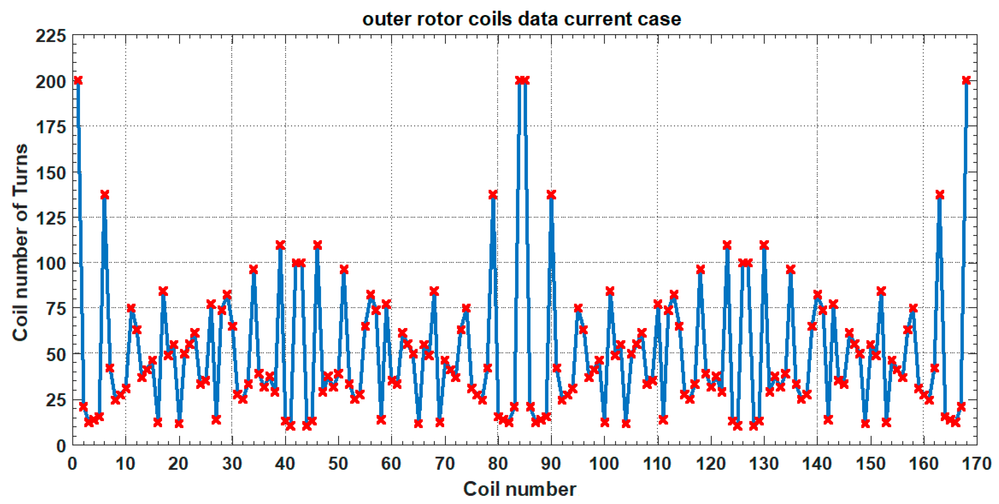
Figure 9.
Number of turns for each outer rotor coil number in Gr1.
Figure 9.
Number of turns for each outer rotor coil number in Gr1.
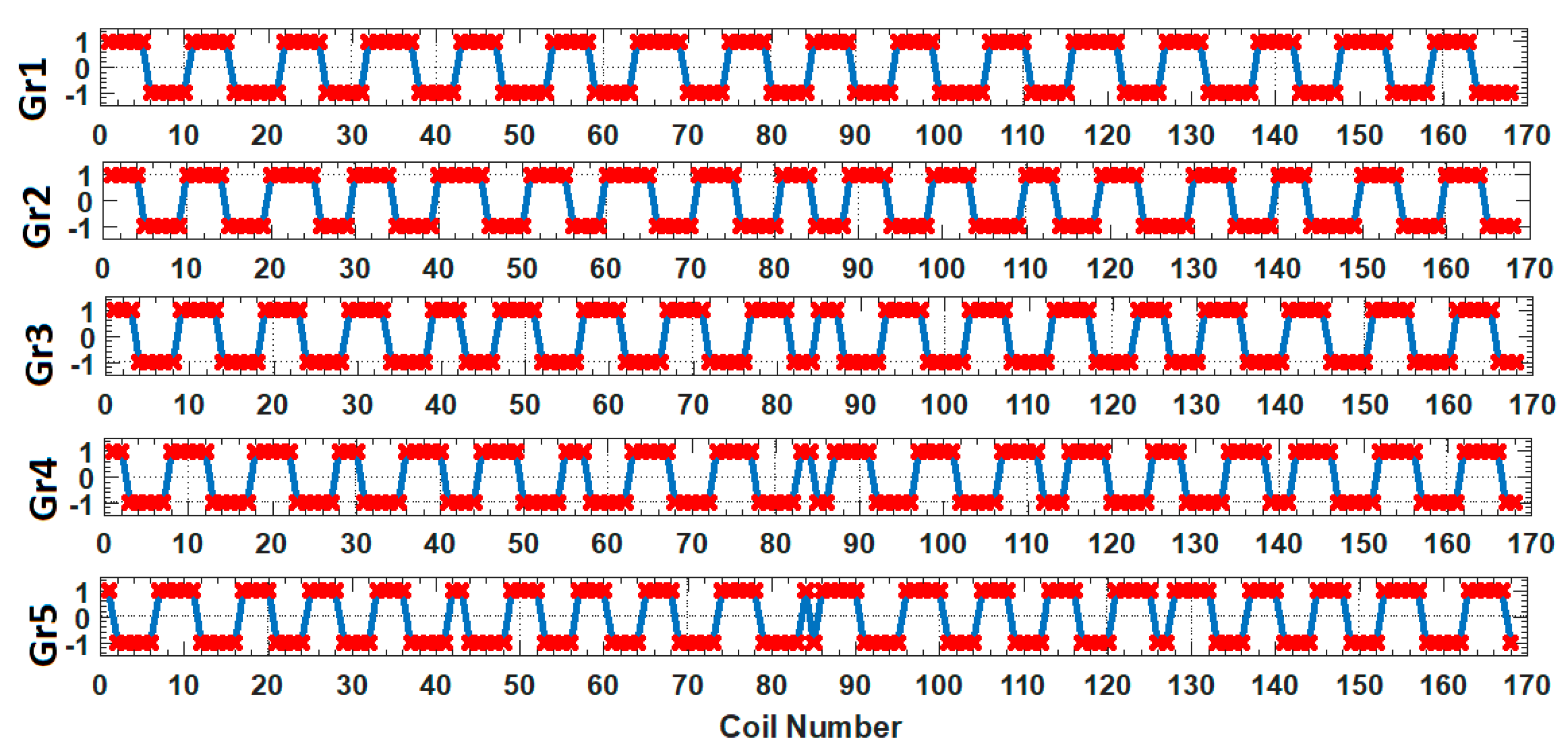
Figure 10.
Outer rotor control signals for the coils in each gear.
Figure 10.
Outer rotor control signals for the coils in each gear.
Figure 11.
Conventional permanent magnetic gear for the first case (= 9, = 25, = 16, = 1.778). (a): Static torque of inner rotor. (b): Variation in the maximum torque on the inner and the outer rotors. (c): Radial flux density waveform in the middle of the inner air gap. (d): Radial flux density waveform in the middle of the outer air gap.
Figure 12.
Proposed magnetic gear 2D models and magnetic field distribution for Gr1.
Figure 12.
Proposed magnetic gear 2D models and magnetic field distribution for Gr1.
Figure 13.
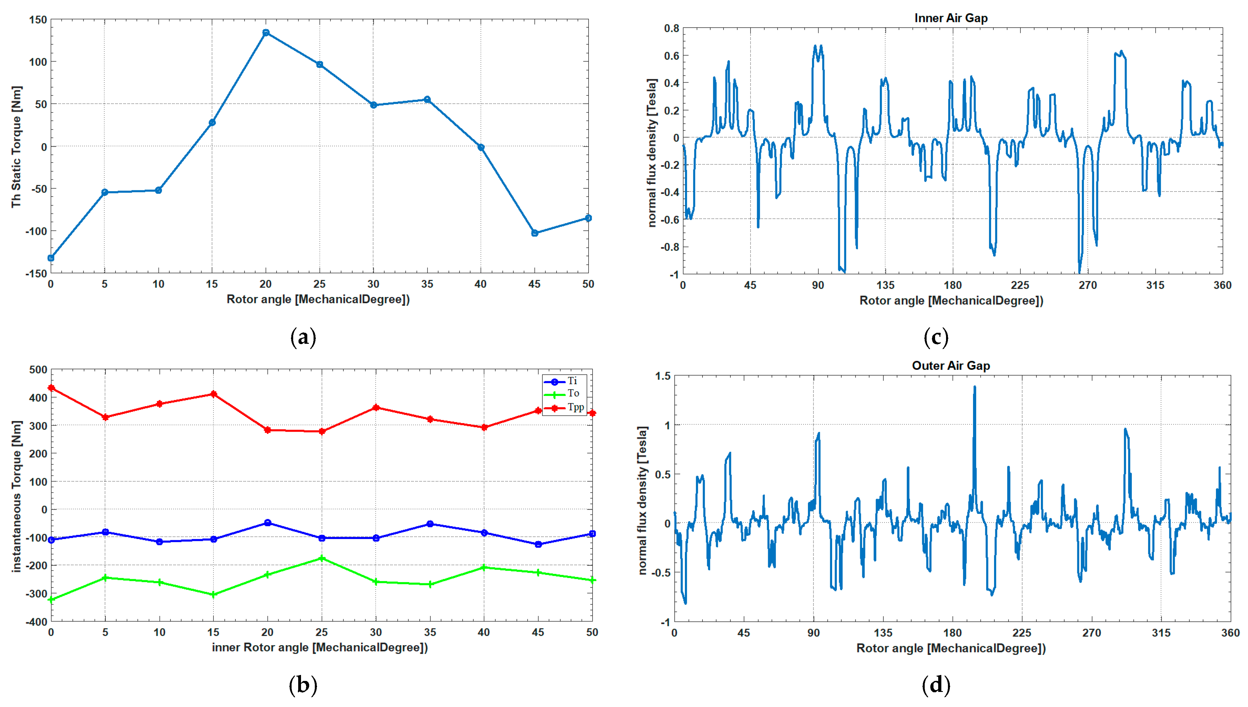
Proposed magnetic gear for the first gear ratio ( = 9, = 25, = 16, = 1.778). (a): Static torque of the inner rotor. (b): Variation in the maximum torque on the inner and the outer rotors. (c): Radial flux density waveform in the middle of the inner air gap. (d): Radial flux density waveform in the middle of the outer air gap.
Figure 14.
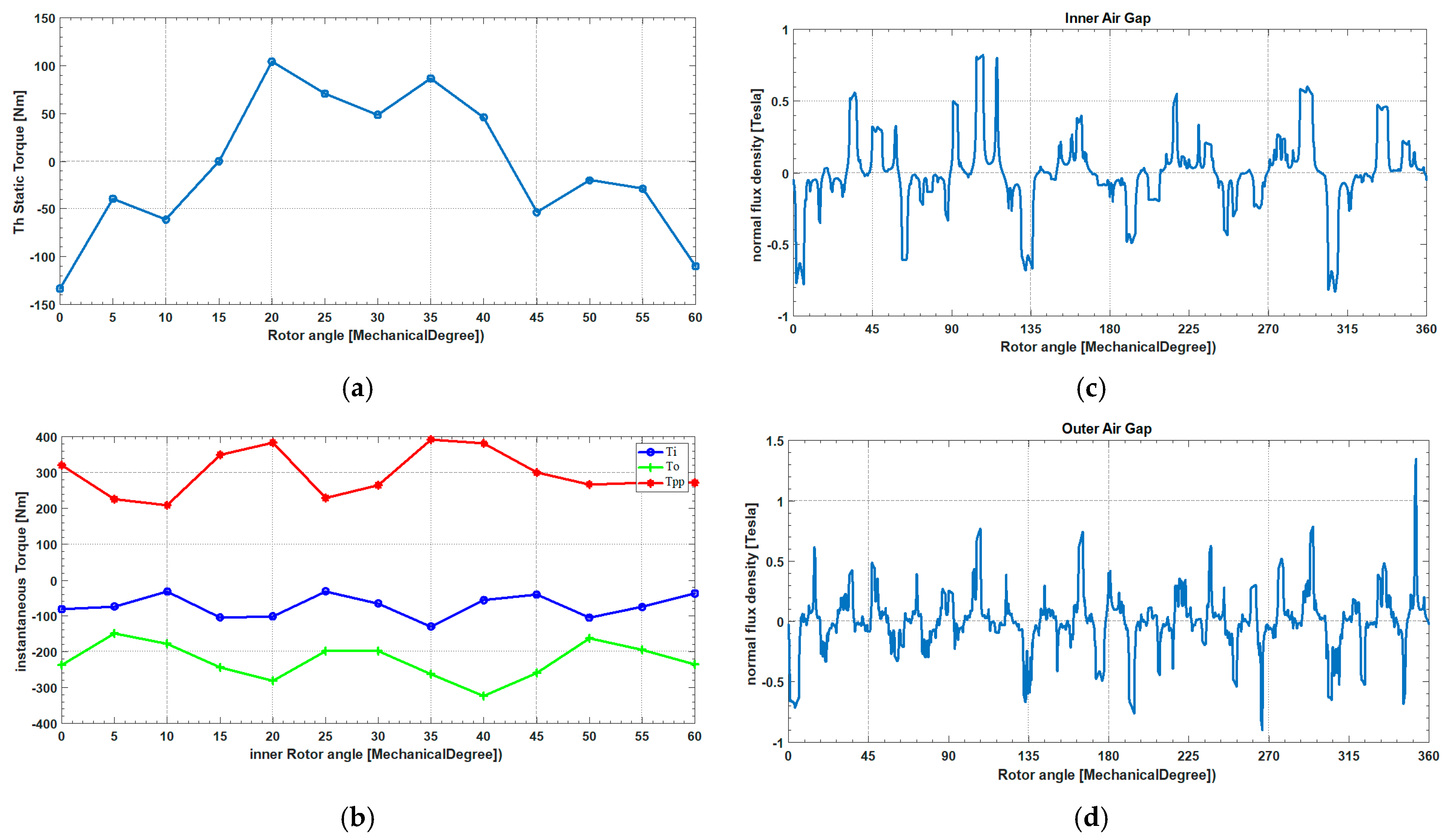
Proposed magnetic gear for the second gear ratio ( = 8, = 25, = 17, = 2.125). (a): Static torque of the inner rotor. (b): Variation in the maximum torque on the inner and the outer rotors. (c): Radial flux density waveform in the middle of the inner air gap. (d): Radial flux density waveform in the middle of the outer air gap.
Figure 15.
Proposed magnetic gear for the third gear ratio ( = 7, = 25, = 18, = 2.571). (a): Static torque of the inner rotor. (b): Variation in the maximum torque on the inner and the outer rotors. (c): Radial flux density waveform in the middle of the inner air gap. (d): Radial flux density waveform in the middle of the outer air gap.
Figure 16.
Proposed magnetic gear for the fourth gear ratio ( = 6, = 25, = 19, = 3.167). (a): Static torque of the inner rotor. (b): Variation in the maximum torque on the inner and the outer rotors. (c): Radial flux density waveform in the middle of the inner air gap. (d): Radial flux density waveform in the middle of the outer air gap.
Figure 17.
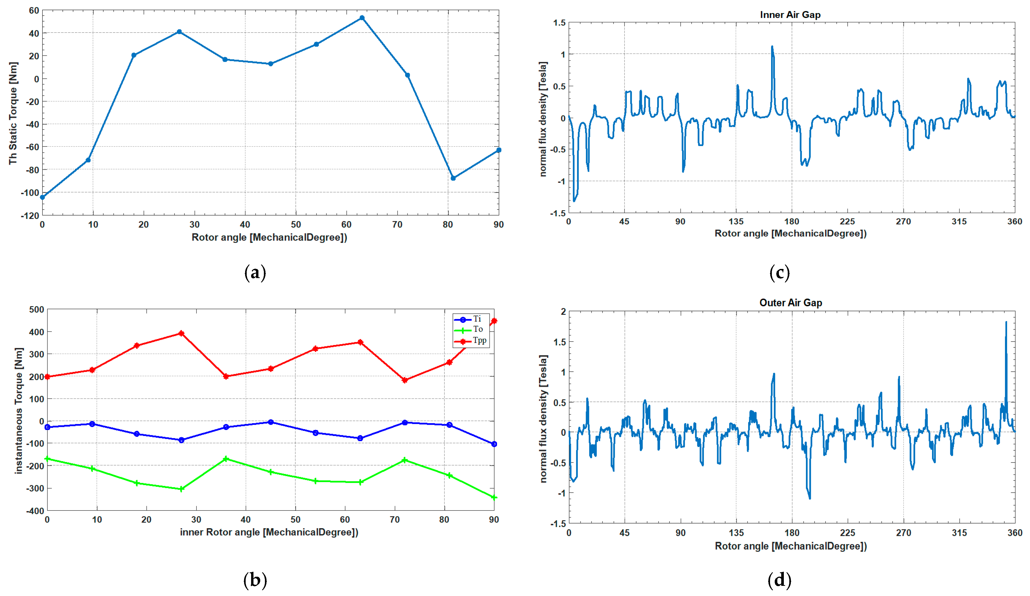
Proposed magnetic gear for the fifth gear ratio ( = 4, = 25, = 21, = 5.25). (a): Static torque of the inner rotor. (b): Variation in the maximum torque on the inner and the outer rotors. (c): Radial flux density waveform in the middle of the inner air gap. (d): Radial flux density waveform in the middle of the outer air gap.
Table 1.
List one of , , , Gr, ppcm, and cbien values.
Table 1.
List one of , , , Gr, ppcm, and cbien values.
| | | Gr | ppcm |
|---|
| 2.0 | 7.0 | 5.0 | 2.5 | 28.0 |
| 2.0 | 9.0 | 7.0 | 3.5 | 36.0 |
| 3.0 | 11.0 | 8.0 | 2.667 | 66.0 |
| 3.0 | 13.0 | 10.0 | 3.333 | 78.0 |
| 4.0 | 15.0 | 11.0 | 2.75 | 120.0 |
| 4.0 | 17.0 | 13.0 | 3.25 | 136.0 |
| 5.0 | 19.0 | 14.0 | 2.8 | 190.0 |
| 5.0 | 21.0 | 16.0 | 3.2 | 210.0 |
| 6.0 | 23.0 | 17.0 | 2.833 | 276.0 |
| 6.0 | 25.0 | 19.0 | 3.167 | 300.0 |
| 7.0 | 25.0 | 18.0 | 2.571 | 350.0 |
| 7.0 | 27.0 | 20.0 | 2.857 | 378.0 |
| 7.0 | 29.0 | 22.0 | 3.143 | 406.0 |
| 7.0 | 31.0 | 24.0 | 3.429 | 434.0 |
| 7.0 | 35.0 | 26.0 | 3.889 | 560.0 |
| 8.0 | 29.0 | 21.0 | 2.625 | 464.0 |
| 8.0 | 31.0 | 23.0 | 2.875 | 496.0 |
| 8.0 | 33.0 | 25.0 | 3.125 | 528.0 |
| 8.0 | 35.0 | 27.0 | 3.375 | 560.0 |
| 9.0 | 37.0 | 28.0 | 3.111 | 666.0 |
| 9.0 | 37.0 | 27.0 | 2.7 | 740.0 |
| 10.0 | 41.0 | 31.0 | 3.1 | 820.0 |
| 10.0 | 43.0 | 33.0 | 3.3 | 860.0 |
Table 2.
Gear ratio combination.
Table 2.
Gear ratio combination.
| | Pi | ns | Po | Gr |
|---|
| Gr1 | 9 | 25 | 16 | 1.778 |
| Gr2 | 8 | 25 | 17 | 2.125 |
| Gr3 | 7 | 25 | 18 | 2.571 |
| Gr4 | 6 | 25 | 19 | 3.167 |
| Gr5 | 4 | 25 | 21 | 5.25 |
Table 3.
High-speed rotor coil turn distributions for each gear.
Table 3.
High-speed rotor coil turn distributions for each gear.
| | Pole Pair | Pole | Turns
/Pole | Total Turns |
|---|
| Gr1 | 9 | 18 | 224 | 4032 |
| Gr2 | 8 | 16 | 252 | 4032 |
| Gr3 | 7 | 14 | 288 | 4032 |
| Gr4 | 6 | 12 | 336 | 4032 |
| Gr5 | 4 | 8 | 504 | 4032 |
Table 4.
High-speed rotor coil turn summation steps.
Table 4.
High-speed rotor coil turn summation steps.
| Gr1 | Gr2 | Gr3 | Gr4 | Gr5 |
|---|
| 224 | 252 | 288 | 336 | 504 |
| 448 | 504 | 576 | 672 | 1008 |
| 672 | 756 | 864 | 1008 | 1512 |
| 896 | 1008 | 1152 | 1344 | 2016 |
| 1120 | 1260 | 1440 | 1680 | 2520 |
| 1344 | 1512 | 1728 | 2016 | 3024 |
| 1568 | 1764 | 2016 | 2352 | 3528 |
| 1792 | 2016 | 2304 | 2688 | 4032 |
| 2016 | 2268 | 2592 | 3024 | |
| 2240 | 2520 | 2880 | 3360 | |
| 2464 | 2772 | 3168 | 3696 | |
| 2688 | 3024 | 3456 | 4032 | |
| 2912 | 3276 | 3744 | | |
| 3136 | 3528 | 4032 | | |
| 3360 | 3780 | | | |
| 3584 | 4032 | | | |
| 3808 | | | | |
| 4032 | | | | |
Table 5.
High-speed rotor coils per group and their distribution numbers among the five gear combinations with their control signal strategies.
Table 5.
High-speed rotor coils per group and their distribution numbers among the five gear combinations with their control signal strategies.
| Coil No. | Turns/
Coil | Total No. Turns | Gr1 | Gr2 | Gr3 | Gr4 | Gr5 |
|---|
| 1 | 224 | 0 | 1 | 1 | 1 | 1 | 1 |
| 2 | 28 | 224 | −1 | 1 | 1 | 1 | 1 |
| 3 | 36 | 252 | −1 | −1 | 1 | 1 | 1 |
| 4 | 48 | 288 | −1 | −1 | −1 | 1 | 1 |
| 5 | 112 | 336 | −1 | −1 | −1 | −1 | 1 |
| 6 | 56 | 448 | 1 | −1 | −1 | −1 | 1 |
| 7 | 72 | 504 | 1 | 1 | −1 | −1 | −1 |
| 8 | 96 | 576 | 1 | 1 | 1 | 1 | −1 |
| 9 | 84 | 672 | −1 | 1 | 1 | 1 | −1 |
| 10 | 108 | 756 | −1 | −1 | 1 | 1 | −1 |
| 47 | 24 | 3784 | 1 | -1 | −1 | −1 | −1 |
| 48 | 224 | 3808 | −1 | −1 | −1 | −1 | −1 |
Table 6.
Low-speed rotor coil turn distributions for each gear.
Table 6.
Low-speed rotor coil turn distributions for each gear.
| | Pole Pair | Pole | Turns/Pole | Total Turns |
|---|
| Gr1 | 16 | 32 | 295 | 9409 |
| Gr2 | 17 | 34 | 277 | 9409 |
| Gr3 | 18 | 36 | 262 | 9409 |
| Gr4 | 19 | 38 | 248 | 9409 |
| Gr5 | 21 | 42 | 225 | 9409 |
Table 7.
Low-speed rotor coil turn summation steps.
Table 7.
Low-speed rotor coil turn summation steps.
| Gr1 | Gr2 | Gr3 | Gr4 | Gr5 |
|---|
| 295 | 277 | 262 | 248 | 225 |
| 589 | 554 | 523 | 496 | 449 |
| 883 | 831 | 785 | 743 | 673 |
| 9409 | 8856 | 8364 | 7924 | 7169 |
| | 9133 | 8625 | 8171 | 7393 |
| | 9409 | 8887 | 8419 | 7617 |
| | | 9148 | 8667 | 7841 |
| | | 9409 | 8914 | 8065 |
| | | | 9162 | 8289 |
| | | | 9409 | 8513 |
| | | | | 8737 |
| | | | | 8961 |
| | | | | 9185 |
| | | | | 9409 |
Table 8.
Low-speed rotor coils per group and their distribution numbers among the five gear combination with their control signal strategies.
Table 8.
Low-speed rotor coils per group and their distribution numbers among the five gear combination with their control signal strategies.
| Coil No. | Turns/
Coil | Total No. Turns | Gr1 | Gr2 | Gr3 | Gr4 | Gr5 |
|---|
| 1 | 225 | 0 | 1 | 1 | 1 | 1 | 1 |
| 2 | 24 | 225 | 1 | 1 | 1 | 1 | −1 |
| 3 | 14 | 249 | 1 | 1 | 1 | −1 | −1 |
| 4 | 16 | 263 | 1 | 1 | −1 | −1 | −1 |
| 5 | 18 | 279 | 1 | −1 | −1 | −1 | −1 |
| 6 | 155 | 297 | −1 | −1 | −1 | −1 | −1 |
| 7 | 48 | 452 | −1 | −1 | −1 | −1 | 1 |
| 8 | 28 | 500 | −1 | −1 | −1 | 1 | 1 |
| 9 | 31 | 528 | −1 | −1 | 1 | 1 | 1 |
| 10 | 35 | 559 | −1 | 1 | 1 | 1 | 1 |
| 167 | 24 | 9161 | −1 | −1 | −1 | −1 | 1 |
| 168 | 225 | 9185 | −1 | −1 | −1 | −1 | −1 |
Table 9.
Dimensions of the conventional magnetic gear.
Table 9.
Dimensions of the conventional magnetic gear.
| Section | Value |
|---|
| Inner radius of the outer rotor (mm) | 541 |
| Inner radius of back iron in the outer rotor (mm) | 636 |
| External radius of the outer rotor (mm) | 765 |
| External radius of the inner rotor (mm) | 400 |
| Shaft radius in the inner rotor (mm) | 142 |
| Inner rotor magnet thickness (mm) | 83 |
| Air gap (mm) | 2 |
| Outer rotor magnet thickness (mm) | 95 |
| Axial length (mm) | 100 |
Table 10.
Details dimensions for the proposed magnetic gear.
Table 10.
Details dimensions for the proposed magnetic gear.
| Thickness (mm) | Radius (mm) |
|---|
| W1 = 175 | R1 = 317 |
| W2 = 83 | R2 = 400 |
| W3 = 2 | R3 = 402 |
| W4 = 137 | R4 = 539 |
| W5 = 2 | R5 = 541 |
| W6 = 95 | R6 = 636 |
| W7 = 129 | R7 = 765 |
| W8 = 142 | R8 = 142 |
Table 11.
The proposed magnetic gear average torque for each case and their obtained gear ratios.
Table 11.
The proposed magnetic gear average torque for each case and their obtained gear ratios.
| Gear Ratio No. | Data According to the Control Strategy | TLav (Nm) | Thav (Nm) | Tppav (Nm) | Obtained Gear Ratio
Gr = TLav/Thav |
|---|
| 1 | = 1.778 | −120.681 | −221.807 | 342.173 | 1.837 |
| 2 | = 2.125 | −102.068 | −208.821 | 310.598 | 2.0459 |
| 3 | = 2.571 | −93.1981 | −250.713 | 343.522 | 2.6901 |
| 4 | = 3.167 | −72.0579 | −225.327 | 297.236 | 3.1270 |
| 5 | = 5.25 | −43.9432 | −242.951 | 286.507 | 5.5288 |
