Abstract
Due to their small size and light mass, small precision cylindrical rollers present challenges in dynamic unbalance detection, including difficulties in measurement and the risk of surface damage. This paper proposes a non-destructive detection device for assessing the dynamic unbalance of small precision cylindrical rollers. The device utilizes an air flotation support method combined with resonance amplification to indirectly measure the dynamic unbalance. A dynamic model of the air flotation tooling-cylindrical roller vibration system was developed to explore the relationship between the vibration parameters of the air flotation tooling and the dynamic unbalance of the cylindrical roller. Modal analysis and harmonic response analysis were performed, revealing that the amplitude of the vibration system at resonance could be detected using the sensor. Additionally, modal testing was conducted to determine the natural frequency of the system. A non-destructive detection platform was constructed for testing the dynamic unbalance of cylindrical rollers. Microscopic observation of the roller surface before and after testing confirmed that the device successfully performs non-destructive detection of dynamic unbalance.
1. Introduction
Recent advancements in aerospace, high-speed rail, and other industries have heightened the focus on bearings, which are crucial components of mechanical systems [1,2,3]. The performance of rotating machinery is often contingent upon the quality of bearings, with cylindrical roller bearings being favored in industrial applications for their superior load-bearing capacity and longevity. As technology progresses, the demands on cylindrical roller bearings have escalated, particularly in high-precision equipment, where bearings must withstand high speeds and impacts while maintaining excellent motion characteristics and an extended service life [4,5]. Manufacturing and assembly processes can introduce variations such as material inconsistencies, shape asymmetries, and internal defects, leading to deviations between the geometric center of rotation and the center of gravity of cylindrical rollers, resulting in dynamic unbalance [6]. In high-speed, high-precision applications, this dynamic unbalance generates periodic forces on the inner and outer raceways and the cage of the bearing, which can lead to operational issues, noise, and other detrimental effects. In severe cases, it may cause damage to the bearing surfaces or lead to catastrophic failure of the cage, significantly impairing bearing performance and reducing its lifespan [7,8,9].
Currently, common dynamic balancing machines, both domestically and internationally, are primarily designed for large-volume and high-mass rotary bodies such as automobile wheel hubs, machine tool spindles, and motor rotors. In contrast, cylindrical rollers, which have relatively smaller volume and mass, present challenges in dynamic unbalance detection. Issues such as detection difficulties and the risk of damaging the surface during detection are more prevalent with these smaller components. Thearle et al. [10] and Baker et al. [11] conducted studies on the detection of dynamic unbalance of rotors and proposed the influence coefficient method for the cases of double-sided, dual-sensors, single-speed, and known points. Assuming that the dynamic unbalance of the rotor is proportional to the vibration feedback it excites, the influence coefficient can be derived by measuring the vibration value at each test point and measuring the dynamic unbalance of the cylindrical roller [12,13]. Louis et al. [14] further modified the influence coefficient method, applied the four-run method to double-sided dynamic unbalance detection, and proposed a new method for detecting double-sided dynamic unbalance of rotor systems without phase response. Bishop and Gladwell [15] proposed the modal balance method, based on the classical vibration theory, which decomposes the dynamic unbalance of the rotor into many rinks of dynamic unbalance components according to the main vibration pattern [16,17]. Kellenberger [18] proposed the N + 2 plane method of modal balancing, in which N balancing planes are used to balance the deflection of the rotor, and two additional correction planes are required if the dynamic reaction force of the rotor is also required to be zero. Abbasi et al. [19] presented a hybrid algorithm integrating the salp swarm algorithm and Nelder–Mead algorithms for detecting unbalance magnitude and phase as the unbalance parameters. Gu et al. [20] of Chongqing University investigated in depth the detection device of the dynamic unbalance influence coefficient and the hardware structure and software construction of the detection system in the computer-aided dynamic unbalance detection machine through the built-in vibration sensor and photoelectric sensor of the dynamic unbalance detection machine. Cui et al. [21,22] and Sui et al. [23] from Henan University of Science and Technology designed a MEMS-based detection system for dynamic unbalance in small-mass cylindrical rollers. This system uses V-block support and a pulley drive to address issues associated with traditional detection systems, such as large swing frame mass, high cost, and low sensitivity.
Conventional dynamic unbalance detection methods predominantly rely on contact-based techniques, which often lead to issues such as interference from additional vibration signals and potential damage to the cylindrical roller’s surface. This paper addresses these challenges by focusing on precision small-mass cylindrical rollers and proposes a non-destructive detection method specifically designed for small dynamic unbalances. A dynamic model of the air flotation tooling-cylindrical roller vibration system (referred to as the vibration system) is developed to explore the relationship between the air flotation tooling and the dynamic unbalance of the cylindrical roller. The high stiffness of the air film supports the cylindrical rollers without causing damage, allowing the centrifugal forces arising from dynamic unbalance to be transferred to the vibration system with minimal interference. By collecting and processing the displacement signals of the vibration system, accurate data on the dynamic unbalance of cylindrical rollers can be obtained. This approach effectively addresses the difficulties associated with detecting dynamic unbalance in small cylindrical rollers and offers a novel solution for the dynamic unbalance detection of other micro and small rotating components.
2. Dynamic Unbalance Non-Destructive Detection Device
2.1. Overall Structure of the Detection Device
The dynamic unbalance detection device is shown in Figure 1. The detection device consists of the displacement sensor, cylindrical roller, and air flotation tooling (including springs, air flotation sleeve, air flotation slide, air flotation guide, detection rod, air inlet interface, and other components).
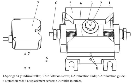
Figure 1.
Schematic diagram of the structure of the detection device.
The dynamic unbalance detection process is as follows: compressed air is passed into the air flotation tooling from the air inlet interface, so that the air flotation slide is suspended in the air flotation guide, and the cylindrical roller is suspended in the air flotation sleeve, as shown in Figure 2. The red represents the air supply system for the air flotation slide, while the green represents the air supply system for the air flotation sleeve. The cylindrical roller to be detected with high-speed rotation is put into the air flotation sleeve. Due to the high rigidity and low damping bearing characteristics of the air film, the cylindrical roller can keep the high-speed rotation for a long time [24]. The cylindrical roller with dynamic unbalance will generate a periodic centrifugal force when rotating at high speed, and this centrifugal force will drive the air flotation slide through the film [25] to vibrate under the support and guidance of the air flotation guide, and the amplitude will reach the maximum when the speed of the cylindrical roller (i.e., the centrifugal excitation frequency) is the same as the natural frequency of the air flotation slide. The displacement sensor collects the vibration signal of the end face of the detection rod, imports it into the information analysis system, carries out the subsequent data processing, and then obtains the dynamic unbalance of the cylindrical roller after the system is solved to complete the detection of the dynamic unbalance of the cylindrical roller.
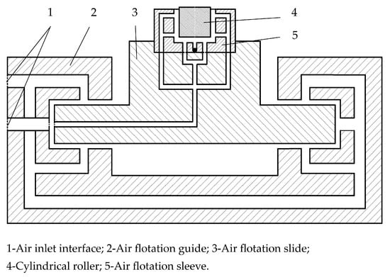
Figure 2.
Schematic diagram of the principle of air flotation support.
The dynamic unbalance detection device proposed in this paper uses the amplification effect of resonance on amplitude to convert the small unbalance into an easily detectable mechanical vibration displacement. During the detection process, the air flotation sleeve provides non-contact air flotation support for the detected cylindrical rollers, which excludes the influence of the outside world on the detection of cylindrical roller dynamic unbalance, protects the surface of cylindrical rollers, and improves the detection accuracy [26]. By replacing different air flotation sleeves, the detection of different types of cylindrical rollers can be satisfied.
2.2. Detection Principle
The vibration system comprises the detection rod, air flotation slide, air flotation sleeve, cylindrical roller, and spring. The air flotation guide constrains five degrees of freedom of the air flotation slide, thereby allowing it to move freely along the x-axis. As the cylindrical roller rotates within the air flotation sleeve, it induces motion in the vibration system along the x-direction. The mass of the vibrating system is collectively constituted by the detection rod, air flotation slide, air flotation sleeve, and cylindrical roller, with the spring contributing a small, negligible mass. The vibration system is abstracted and simplified to obtain a vibration system dynamics model that is convenient for calculation and analysis. The model can reflect the dynamics of the detection device and the dynamic response relationship between the detection device and the dynamic unbalance of the cylindrical roller to provide a theoretical basis for analyzing the motion characteristics of the vibration system.
Let the eccentric mass of the cylindrical roller be . The mass eccentricity distance is and the dynamic unbalance is defined as . When the cylindrical roller rotates with angular velocity , the centrifugal force generated by the eccentric mass is as follows:
The cyclic centrifugal force on the air flotation sleeve in the direction of vibration of the air flotation slide is as follows:
where is the initial phase of the force on the air flotation sleeve. The reference position for the phase is in the x-positive direction.
Figure 3 illustrates a simplified dynamic model of the vibrating system, with and denoting the stiffness and damping coefficients of the air film in the air flotation sleeve, and and representing the stiffness and damping coefficients of the vibrating system in the x-direction. Given that the air film stiffness significantly surpasses the spring stiffness, an approximation can be made that, under the influence of the excitation force, the air film behaves as purely rigid. The excitation force exclusively induces deformation in the spring, while the damping coefficient solely impacts the rotation of the cylindrical roller. Consequently, the vibrating system exhibits a stiffness coefficient along the x-direction, denoted as , and a damping coefficient, denoted as . Notably, the stiffness coefficient can be reasonably approximated as the superposition of the stiffness of two springs depicted in Figure 1.
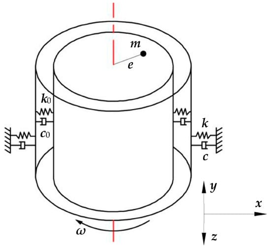
Figure 3.
Simplified dynamic model of a vibration system.
Establishing a Cartesian coordinate system with the guide length direction designated as the x-direction, the air flotation guide constrains the air flotation slide in five degrees of freedom. When the cylindrical roller undergoes angular velocity , under the approximation that the vibration system can be treated as a single-degree-of-freedom system with damped forced vibration, the dynamic unbalance-induced excitation force compels the slide to undergo periodic vibrations along the x-direction. The resulting differential equation of motion is as follows:
where is the vibration system damping coefficient; is the vibration system’s natural frequency; is the excitation force amplitude; is the vibration system mass; is the excitation force frequency, and is the damping coefficient, the general solution of the differential equation is:
where and are the integration constants; is the phase angle of the forced vibration behind the excitation force, determined by the initial conditions of the vibration.
The damped forced vibration consists of two parts: the first part is the free vibration whose frequency is the natural frequency, and the second part is the forced vibration whose frequency is the frequency of the excitation force. Since there is always damping in the actual vibration system, the free vibration part will decay down quickly, so we focus on the second part of the steady state forced vibration. The amplitude is as follows:
Because of the small cylindrical roller dynamic unbalance, the excitation force generated is also very weak, and the vibration system displacement information is difficult to accurately detect. As can be seen from Equation (6), when the frequency of the excitation force tends to the vibration system’s natural frequency, the amplitude increases significantly; that is, , and the vibration system resonance is as follows:
When the frequency of the excitation force satisfies Equation (7), the maximum amplitude is obtained as follows:
That is, the air flotation slide has the maximum amplitude at resonance, the use of resonance to amplify the vibration response can better extract the vibration signal of the cylindrical roller dynamic unbalance, and Equation (8) is converted to get the dynamic unbalance calculation formula as follows:
Through the inverse of Equation (9), to find the dynamic unbalance you need to know the natural frequency of the vibration system. The vibration system is simplified to a simple spring-mass system, establishing a single-degree-of-freedom system vibration differential equation and solving the vibration system’s natural frequency as follows:
where is the vibration system stiffness coefficient, which is approximated as the superposition of the two spring stiffness coefficients in Figure 1.
3. Vibration System Simulation Analysis
In order to obtain the natural frequency of the vibration system and the motion characteristics of the vibration system under the action of external excitation force, the harmonic response simulation analysis of the vibration system is carried out by the modal superposition method. The basic idea is to carry out the modal analysis first to obtain the natural frequency of the vibration system and then carry out the harmonic response analysis on the results of the analysis.
The 3D modeling software SolidWorks 2023 was used to build the 3D model of the air flotation tooling, and the 3D model was imported into the model module of Ansys Workbench to set the material parameters of the vibration system. The material is aluminum alloy, the modulus of elasticity is 70 GPa, Poisson’s ratio is 0.33, and the density is 2770 kg/m3. The 3D model is shown in Figure 4, after completion.
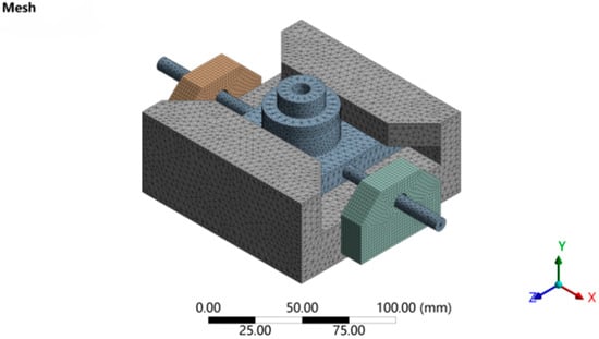
Figure 4.
Mesh division model.
The boundary conditions are set for the finite element model after the mesh is divided. The frictionless contact between the air flotation slide and the air flotation guide is set (the air film is considered a frictionless rigid support for the air flotation slide), and the x-direction is the vibration direction of the air flotation slide, so the x-direction degrees of freedom are retained, and displacement constraints are applied to the y-direction and z-direction. The spring stiffness is set to 5 N/mm, and the harmonic response analysis uses a damping ratio model with a damping ratio of 0.02. After setting up, the solution is calculated to extract the first six mode shapes system. The first six orders are shown in Figure 5.
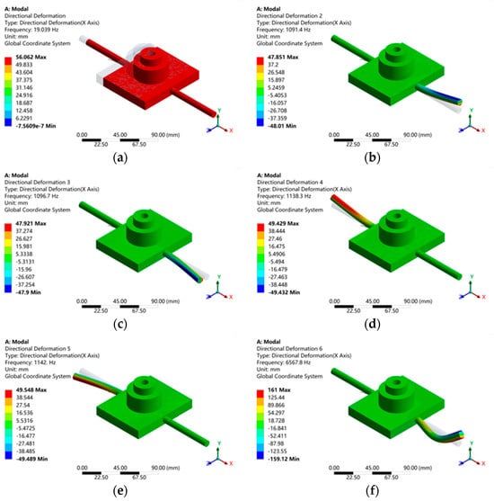
Figure 5.
The first six vibration modes of the air flotation slide. (a) First−order vibration diagram. (b) Second−order vibration diagram. (c) Third−order vibration diagram. (d) Fourth−order vibration diagram. (e) Fifth−order vibration diagram. (f) Sixth−order vibration diagram.
As shown in Figure 5, the first six orders of modes of the vibrating system are 19.039 Hz, 1091.4 Hz, 1096.7 Hz, 1138.3 Hz, 1142.0 Hz, and 6567.8 Hz. The analysis results show that the first-order mode of the vibration system vibrates along the x-direction with a frequency of about 19.039 Hz.
After the end of the modal analysis, a harmonic response analysis is performed, and the force load is added in the x-direction of the vibration system as the excitation force of the vibration system. The frequency of the excitation force is the rotational speed of the cylindrical roller, the magnitude of the excitation force simulates the centrifugal force generated by the cylindrical roller at different rotational speeds, and the numerical magnitude can be obtained from Equation (1). Set the frequency range of excitation force 0–50 Hz and execute the solution. After the solution is completed, the displacement values of the vibration system in the x-direction are extracted. The results are shown in Figure 6.
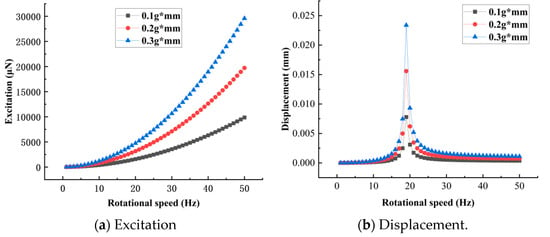
Figure 6.
Harmonic response analysis.
The harmonic response analysis employs a damping ratio model with a damping ratio of 0.02. This analysis aims to assess the feasibility of the proposed device rather than providing a precise quantitative evaluation, and thus, the results should be interpreted with this in mind. The excitation force induced by the rotation of the cylindrical roller causes the vibration system to oscillate. The frequency of this excitation force corresponds to the rotational speed of the cylindrical roller, and the magnitude of the excitation force is equivalent to the centrifugal force exerted by the cylindrical roller. The centrifugal force can be calculated using Equation (1), where , represents the frequency of the excitation force, and denotes the dynamic unbalance of the cylindrical roller. By substituting the rotational speeds of the cylindrical roller ranging from 0 to 50 Hz into Equation (1), the excitation force at each frequency of the vibration system can be determined. The harmonic response analysis was performed for each Hz increment, totaling 50 calculations.
From Figure 6, it can be seen that the amplitude gradually increases in the range of 0–19 Hz, and when it reaches near 19 Hz (near the resonance point), the amplitude reaches the maximum, and the amplitude near the resonance point has a significant increase compared with the amplitude when it is not resonant. Thus, it can be theoretically concluded that it is highly feasible to use the resonance amplification effect to detect the dynamic unbalance of cylindrical rollers. Without using the resonance amplification effect, the excitation force caused by the cylindrical roller dynamic unbalance is very weak, and it is difficult to make the air flotation slide produce significant displacement in the x-direction. Although this micro-displacement information can be collected by using ultra-high-precision displacement sensors, it is not feasible to improve the sensor accuracy in one go, considering the cost and external input interference.
4. Test
4.1. Vibration System Modal Test
To obtain the actual natural frequency of the vibration system and verify the accuracy of the theoretical calculation and simulation analysis results, the modal test of the vibration system is required. The modal test system mainly consists of the force hammer, air flotation tooling, three-way acceleration sensor, data acquisition device, data analyzer, and electric charge amplifier (air supply conditions are consistent with Section 4.2). The block diagram of the testing system is shown in Figure 7.
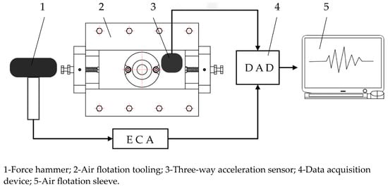
Figure 7.
Modal test system.
Test method: Since the structure of the vibration system is simple and the modal test only focuses on the vibration frequency of the air flotation slide along the x-direction, a single-point excitation and single-point vibration pick-up test can meet the needs. The three-way acceleration sensor (EA-YD-193) was used to collect the required test data, and the excitation method was chosen from the force hammer (LC-40A). The excitation point of the force hammer is the end face of the detection rod, and the direction is along the x-direction. The built vibration system dynamics test platform is shown in Figure 8.
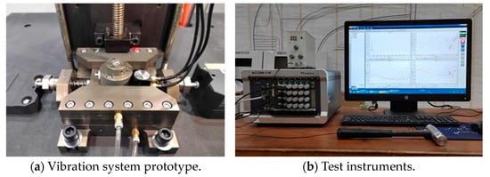
Figure 8.
Vibration system dynamics test platform.
The individual spring specifications of the vibration system under test were as follows: the wire diameter–outside diameter–length was 1 mm–12 mm–20 mm, the spring stiffness coefficient was 2.2525 N/mm, and the vibration system mass was 356 g. The modal data were collected several times using Text EngineX software, and the collected data were imported into Modal Genius software for analysis. The three-way acceleration sensor had a mass of about 18 g, which is much less than the mass of the vibration system (356 g). Its location is shown in Figure 7. The attachment of the three-way accelerometer to the air flotation slide is bound to introduce additional disturbances to the vibration system, but due to its small mass, the disturbances it introduces to the modal test can be acceptable. According to the analysis of the modal parameters by the analysis software, the natural frequency of the vibration system in the x-direction is 18.32 Hz.
4.2. Cylindrical Roller Dynamic Unbalance Detection
To verify the practicality of the cylindrical roller dynamic unbalance detection device, we built a non-destructive testing platform for cylindrical roller dynamic unbalance detection, which mainly consists of the cylindrical roller, driving device, air flotation tooling, laser displacement sensor (LK-H008, 0.0001 mm), and laser tachometer (UT372, 0.1 rpm) [27,28]. The laser displacement sensor mainly completes the vibration signal collection, and the laser tachometer is used to monitor the cylindrical roller speed in real time.
Before performing dynamic unbalance detection on cylindrical rollers, it is essential to calibrate the rollers for dynamic unbalance. Six cylindrical rollers, which are precision-machined with the same weight and dimensional specifications, were selected and labeled from 0 to 5. The end faces of rollers 1 through 5 were laser-etched to reduce their weight, and a specific gradient of dynamic unbalance was manually introduced. The roller labeled 0 was retained as a reference for comparison. Multiple measurements of the reduced weight and eccentricity were conducted to determine the calibration dynamic unbalance of the cylindrical rollers.
The de-weighting method is as follows: operate the CNC system of the laser etching machine for centering, find the center of the cylindrical roller as the coordinate origin, and then set the etching point position. The distance between the etching point position and the center of the circle is the eccentricity distance. The rollers after etching are shown in Figure 9.
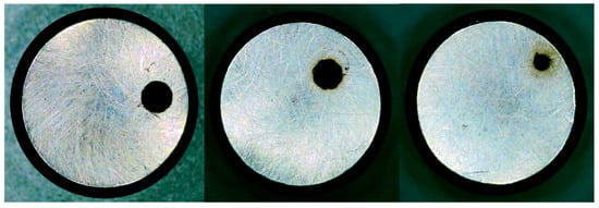
Figure 9.
De-weighting diagram.
As shown in Table 1, the cylindrical roller dynamic unbalance mark was completed. In the cylindrical roller dynamic unbalance detection test, adjust the air flotation sleeve air supply pressure of 0.15 MPa, air flotation guide air supply pressure of 0.3 MPa, spring specifications, modal test with the same spring, and the laser displacement sensor installation to ensure that the sensor surface and the distance between the detection rod is 8 ± 0.5 mm. The dynamic unbalance of the cylindrical roller non-destructive detection test platform is shown in Figure 10.

Table 1.
Cylindrical roller calibration dynamic unbalance.
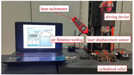
Figure 10.
Non-destructive testing platform for cylindrical roller dynamic unbalance detection.
At the beginning of the test, the cylindrical roller to be detected is put into the air flotation sleeve, the cylindrical roller is kept in suspension in the air flotation sleeve, the driving device descends and drives the cylindrical roller to rotate at high speed when the rotational speed reaches 6000 rpm, the driving device is detached from the cylindrical roller, and the cylindrical roller relies on its inertia to rotate freely at high speed in the air flotation sleeve. The laser displacement sensor starts to collect vibration signals, the collected vibration signals are transmitted to the computer through the data acquisition device, and the collected signals are processed by the analysis software to get the cylindrical roller dynamic unbalance detection data. The displacement detection data for cylindrical rollers No. 2 and No. 0 are shown in Figure 11.
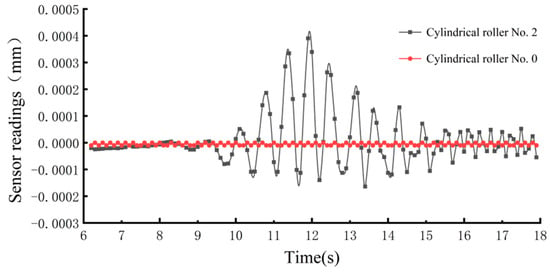
Figure 11.
Displacement detection results.
The cylindrical roller in the air flotation sleeve speed is gradually reduced, and the excitation force frequency is also gradually reduced (to a rotational speed that is the frequency of the cylindrical roller excitation force) when the rotational speed is close to the vibration of the system’s natural frequency of 18.32 Hz resonance. At this time, the rotational speed is 1150 rpm (corresponding to the frequency of the excitation force of 18.64 Hz). Repeat the test 10 times for cylindrical rollers Nos. 1–5 under the same test conditions respectively, extract the amplitude data, observe the amplitude deviation of cylindrical rollers under the same dynamic unbalance, and judge the stability of the test results. The curve is shown in Figure 12.
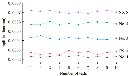
Figure 12.
Repeatability test results.
As shown in Figure 12, the amplitude of cylindrical rollers with the same dynamic unbalance was basically the same under the test platform, with good repeatability, and with the increase of the dynamic unbalance, the amplitude detected by the sensor increases and also maintains a certain degree of repeatability, which shows that the test data have a certain degree of reliability.
Ten sets of amplitude values detected for each cylindrical roller were averaged to obtain the average value of the amplitude of the vibration system under different dynamic unbalance, as shown in Table 2.

Table 2.
The average values of the amplitude of the vibration system.
Substituting the cylindrical roller dynamic unbalance and the corresponding amplitude of Nos. 1–5 and the known parameters of the vibration system into Equation (9), the corresponding equations of cylindrical roller dynamic unbalance and amplitude are obtained approximately:
The damping coefficient can be considered constant since the damping of the air film on the air flotation slide is extremely small and the spring undergoes only a uniform micro-deformation. From Equation (11), the function is a linear function, which is linearly fitted using Origin software 2023, and the fitting results are shown in Figure 13.
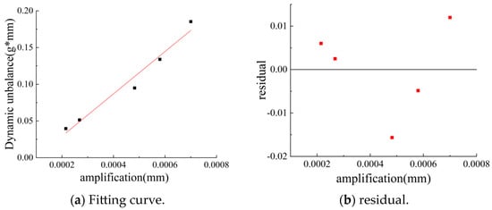
Figure 13.
Fitting results of the formula for the dynamic unbalance.
From Figure 13, the slope of the fitted function is 287.91323 ± 29.955, the intercept is 0.02823 ± 0.01453, and the variance of the fitted function is 0.96855, which is greater than 0.9, so the fit is better. The residual plot was obtained by making a scatter plot with the average amplitude of the vibration system as the independent variable and the residual as the dependent variable. The more random the distribution of the residuals, the more reliable the regression results obtained, and the fitted function is more reliable, as can be seen in Figure 13. Therefore, the fitted function can be considered reliable and the relationship between the amplitude and the dynamic unbalance under this vibration system is given in the following equation.
The average value of the measured amplitude is substituted into Equation (12) to calculate the dynamic unbalance, which is compared with the calibrated dynamic unbalance, and the result is shown in Figure 14.
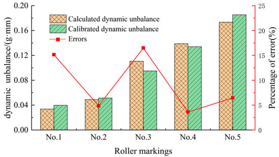
Figure 14.
Error histogram.
As can be seen from Figure 14, the calculated value of the dynamic unbalance is basically close to the calibrated value of the dynamic unbalance, with a maximum error of 16.3%, and the fitted function represents the relationship between the amplitude and the dynamic unbalance better. The error was analyzed for the following reasons: the calculation formula is a simplified ideal model, and the actual vibration system is different from the ideal model because of the structure; the external environment will have a certain impact on the measurement of the laser sensor during the measurement, and the resulting amplitude is mixed with vibrations generated by other factors; the number of samples of the fitting function is not enough, and the fitted results will have a certain degree of error; in addition, the damping characteristics of the vibrating system are not very stable, which contributes to the fluctuations in the curves in Figure 12.
4.3. Cylindrical Roller Non-Destructive Detection Test Verification
Cylindrical rollers need to be put into use in the bearings after the dynamic unbalance detection, so there cannot be any damage to the surface of the cylindrical roller during the detection process, which needs to be calibrated to see if the detection device realizes non-destructive detection of the surface of the cylindrical roller.
All the cylindrical roller samples before and after the test of dynamic unbalance detection were put under the microscope to observe and record the surface quality of the cylindrical roller, and the comparison of the surface quality of the cylindrical roller before and after the detection is shown in Figure 15.
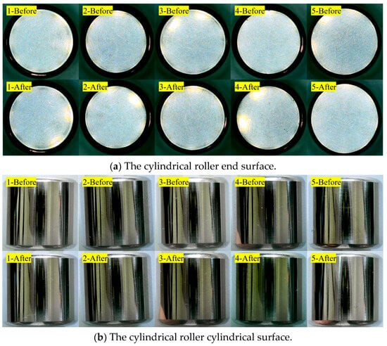
Figure 15.
Comparison of surface quality of cylindrical roller before and after detection.
As can be seen from Figure 15, the end face and column surface of the cylindrical roller after the detection are not different from those before the detection, the cylindrical roller moves smoothly and noiselessly in the air flotation sleeve during the whole test process, and it is considered that the detection device can realize the non-destructive detection of the dynamic unbalance of the cylindrical roller.
5. Conclusions
The precision cylindrical roller’s existing micro-dynamic unbalance problem is one of the key factors affecting the performance and service life of rolling bearings, and at present, the industry commonly uses means of dynamic unbalance detection, so there is a large detection difficulty and detection of the surface damage and other problems. These problems seriously constrain the development of the non-destructive detection technology of dynamic unbalance. In order to solve these problems, this paper proposes proposed a new detection method, established a dynamic model of the vibration system, and carried out a modal analysis and harmonic response analysis of the vibration system. The analytical results show that the detection device can detect the micro-dynamic unbalance of the cylindrical roller.
To verify the feasibility of the proposed method, a non-destructive testing platform for cylindrical roller dynamic unbalance was constructed. The experimental results show that the cylindrical roller with dynamic unbalance has a significant amplitude value when its rotational speed is close to the natural frequency of the vibration system, which proves that the detection device can realize the detection of the dynamic unbalance of the cylindrical roller. Microscopic observation tests were carried out on the surface of the cylindrical roller before and after the detection, and the results showed that there was no obvious damage to the surface of the cylindrical roller, which proved that the detection device could realize non-destructive detection of the cylindrical roller’s dynamic unbalance.
The non-destructive detection device of cylindrical roller dynamic unbalance proposed in this paper adopts a non-destructive air flotation bearing method, which reduces the damage to the surface of the cylindrical roller compared with the traditional destructive contact bearing method. In addition, due to the detection principle based on the resonance amplification effect, the detection accuracy of the device is greatly improved compared to the traditional “soft support” detection method. In the future, we will strive to optimize and improve the structure of the detection device, in order to significantly improve the detection stability of the device and reduce the manufacturing cost, as well as to meet the more demanding needs of the non-destructive detection of dynamic unbalance.
6. Patents
- Duan, M.; Liang, S. A Kind of Cylindrical Roller Bearing Roller High-Speed Rotation Driving Device and Driving Method. CN115979513A, 18 April 2023.
- Duan, M.; Liang, S. A Device and Method for Driving a Cylindrical Roller to Rotate at High Speed in an Air-Floating State. CN115950584A, 11 April 2023.
- Duan, M.; Liang, S. A High-Speed Bearing Small Mass Cylindrical Roller Rotation Speed Obtaining Device. CN217059169U, 26 July 2022.
Author Contributions
Writing—original draft preparation, Z.Z. and B.Y.; writing—review and editing, B.Y. and Y.C.; data curation, S.L. and B.Y.; validation, M.D. and Z.Z.; conceptualization, R.G. and S.L.; methodology, Y.C.; software, S.L. and Y.C.; supervision, R.G. and M.D.; funding acquisition, R.G. project administration, Z.Z. and M.D. All authors have read and agreed to the published version of the manuscript.
Funding
This research was funded by the National Natural Science Foundation of China, grant number 52005158, and the Henan Province science and technology research project (Research on key technology of high-speed micro cylindrical roller dynamic unbalance non-destructive detection system), grant number 242102220078. The APC was funded by Henan University of Science and Technology.
Institutional Review Board Statement
Not applicable.
Informed Consent Statement
Not applicable.
Data Availability Statement
The data presented in this study are available upon request from the corresponding author.
Conflicts of Interest
The authors declare no conflict of interest.
References
- He, C.; Zhang, J.; Geng, K.; Wang, S.; Luo, M.; Zhang, X.; Ren, C. Advances in ultra-precision machining of bearing rolling elements. Int. J. Adv. Manuf. Technol. 2022, 122, 3493–3524. [Google Scholar] [CrossRef]
- Xu, F.; Ding, N.; Li, N.; Liu, L.; Hou, N.; Xu, N.; Chen, X. A review of bearing failure Modes, mechanisms and causes. Eng. Fail. Anal. 2023, 152, 107518. [Google Scholar] [CrossRef]
- Li, X.; Horie, M.; Kagawa, T. Study on the basic characteristics of a vortex bearing element. Int. J. Adv. Manuf. Technol. 2013, 64, 1–12. [Google Scholar] [CrossRef]
- Wang, D.; Yuan, J.; Hu, L.; Lyu, B. Multidimensional study on the wear of high-speed, high-temperature, heavy-load bearings. Materials 2023, 16, 2714. [Google Scholar] [CrossRef]
- Hou, X.; Diao, Q.; Liu, Y.; Liu, C.; Zhang, Z.; Tao, C. Failure Analysis of a Cylindrical Roller Bearing Caused by Excessive Tightening Axial Force. Machines 2022, 10, 322. [Google Scholar] [CrossRef]
- Cui, Y.; Deng, S.; Niu, R.; Chen, G. Vibration effect analysis of roller dynamic unbalance on the cage of high-speed cylindrical roller bearing. J. Sound Vib. 2018, 434, 314–335. [Google Scholar] [CrossRef]
- Tiwari, R.; Chakravarthy, V. Simultaneous estimation of the residual unbalance and bearing dynamic parameters from the experimental data in a rotor-bearing system. Mech. Mach. Theory 2009, 44, 792–812. [Google Scholar] [CrossRef]
- Harsha, S.P. Nonlinear dynamic analysis of an unbalanced rotor supported by roller bearing. Chaos Solitons Fractals 2005, 26, 47–66. [Google Scholar] [CrossRef]
- Wang, A.; Yao, W. Theoretical and numerical studies on simultaneous identification of rotor unbalance and sixteen dynamic coefficients of two bearings considering unbalance responses. Int. J. Control Autom. Syst. 2022, 20, 1971–2007. [Google Scholar] [CrossRef]
- Therale, E.L. Dynamic balancing of rotating machinery in the field. ASME J. Appl. Mech. 1934, 56, 745–753. [Google Scholar] [CrossRef]
- Baker, J.G. Methods of rotor-unbalance determination. ASME J. Appl. Mech. 1939, 61, A1–A6. [Google Scholar] [CrossRef]
- Zhang, X.; Jiao, H.; Hu, D. Research progress on field dynamic balancing methods for rotating machinery. J. Mech. Electr. Eng. 2021, 38, 1367–1377. (In Chinese) [Google Scholar]
- Zhang, L.; Duan, Z.; Li, D. Research progress of on-site dynamic balancing technology. Chem. Eng. Mach. 2012, 39, 690–694. (In Chinese) [Google Scholar]
- Louis, J. Two-plane balancing of a rotor system without phase response measurements. Trans. ASME J. Vib. Acoust. Stress Reliab. Des. 1987, 109, 162–167. [Google Scholar]
- Bishop, R.E.D.; Gladwell, G.M.L. The Vibration and Balancing of an Unbalanced Flexible Rotor. J. Mech. Eng. Sci. 1959, 1, 66–70. [Google Scholar] [CrossRef]
- Zou, D.; Zhao, H.; Liu, G. Application of augmented Kalman filter to identify unbalance load of rotor-bearing system: Theory and experiment. J. Sound Vib. 2019, 463, 68–69. [Google Scholar] [CrossRef]
- Parkinson, A.G. Balancing of rotating machinery. Proc. Inst. Mech. Eng. Part C J. Mech. Eng. Sci. 1991, 205, 61–63. [Google Scholar] [CrossRef]
- Kellenberger, W. Should a flexible rotor be balanced in N or (N+2) planes. J. Eng. Ind. 1972, 94, 548–560. [Google Scholar] [CrossRef]
- Abbasi, A.; Firouzi, B.; Sendur, P. Identification of unbalance characteristics of rotating machinery using a novel optimization-based methodology. Soft Comput. 2022, 26, 4831–4862. [Google Scholar] [CrossRef]
- Gu, Q.; Tang, Y. Research on computer-aided dynamic balancing machine measurement and analysis system. Mech. Sci. Technol. 1992, 4, 24–27. [Google Scholar]
- Cui, Y.; Deng, S.; Yang, H.; Zhang, W.; Niu, R. Effect of cage dynamic unbalance on the cage’s dynamic characteristics in high-speed cylindrical roller bearings. Ind. Lubr. Tribol. 2019, 71, 1125–1135. [Google Scholar] [CrossRef]
- Cui, Y.; Deng, S.; Ni, Y.; Chen, G. Effect of roller dynamic unbalance on cage stress of high-speed cylindrical roller bearing. Ind. Lubr. Tribol. 2018, 70, 1580–1589. [Google Scholar] [CrossRef]
- Sui, X.; Liu, C.; Li, J.; Xue, Y.; Yu, Y.; Cui, Y. Laser-based measurement for micro-unbalance of cylindrical rollers of the high-speed precision rolling bearings. Clust. Comput. 2019, 22, S9159–S9167. [Google Scholar] [CrossRef]
- Liu, D.; Liu, Y.; Chen, S. Hydrostatic Gas Lubrication, 1st ed.; Harbin Institute of Technology: Harbin, China, 1990; pp. 51–121. [Google Scholar]
- Chen, G.; Ge, Y.; Lu, Q.; Zhang, W.; Wang, S. Air film pressure field characteristics of aerostatic thrust bearing with orifice blockage. Int. J. Adv. Manuf. Technol. 2023, 124, 4317–4328. [Google Scholar] [CrossRef]
- Liang, S.; Duan, M.; Zhang, Z. Development and Investigation of Non-Destructive Detection Drive Mechanism for Precision Type Cylindrical Roller Dynamic Unbalance. Appl. Sci. 2023, 13, 13266. [Google Scholar] [CrossRef]
- Venturini, S.; Cavallaro, S.P.; Vigliani, A. Experimental Techniques for Flywheel Energy Storage System Self-discharge Characterisation. In Proceedings of the International Conference of IFToMM ITALY, Turin, Italy, 11–13 September 2024; Springer: Berlin/Heidelberg, Germany, 2024; pp. 183–191. [Google Scholar]
- Jin, X.; Liu, Y. Numerical and Experimental Analysis for the Dynamics of Flawed–Machining Rod–Disk Rotor with Inner Misalignment. Machines 2022, 10, 355. [Google Scholar] [CrossRef]
Disclaimer/Publisher’s Note: The statements, opinions and data contained in all publications are solely those of the individual author(s) and contributor(s) and not of MDPI and/or the editor(s). MDPI and/or the editor(s) disclaim responsibility for any injury to people or property resulting from any ideas, methods, instructions or products referred to in the content. |
© 2024 by the authors. Licensee MDPI, Basel, Switzerland. This article is an open access article distributed under the terms and conditions of the Creative Commons Attribution (CC BY) license (https://creativecommons.org/licenses/by/4.0/).