Article

Configuration and Parameter Optimization Design of a Novel RBR-2RRR Spherical Hybrid Bionic Shoulder Joint

School of Mechanical Engineering, Yanshan University, Qinhuangdao 066004, China
*
Author to whom correspondence should be addressed.
Machines 2024, 12(10), 683; https://doi.org/10.3390/machines12100683
Submission received: 16 August 2024 / Revised: 24 September 2024 / Accepted: 26 September 2024 / Published: 29 September 2024
(This article belongs to the Section Machine Design and Theory)

Abstract

:
To improve the workspace, linear displacement stiffness, and driving torque utilization of humanoid robot shoulder joint mechanisms, an offset-designed RBR-2RRR (R represents the revolute pair, and B represents the ball cage joint) spherical hybrid bionic shoulder joint configuration (SHBSJC) is proposed and its structural parameters are optimized. Firstly, the shoulder joint’s physiological structure is biomimetically designed, a prototype mechanism of RBR-2RRR SHBSJC is proposed, and its kinematics are solved. The deformation response of RBR-2RRR and 3-RRR under the same load is compared to verify the obtained configuration can improve the linear displacement stiffness. Considering the workspace and singularity, using the GCI and GDCI as optimization functions, the recommended and adopted values of structural parameters are obtained. The distribution diagrams of the LCI and LDCI demonstrate that the configuration meets performance expectations. To further increase the prototype mechanism’s workspace and match the human shoulder joint’s motion range, an offset-designed RBR-2RRR SHBSJC is proposed, and the offset angle, installation posture angle, and spatial mapping relationship of the mechanism are determined. The results of workspace comparison and virtual model machine action simulation indicate that the final configuration meets the workspace expectations. This work enriches the shoulder joint configuration types and has engineering application value.

1. Introduction

The joint mechanism of a robot is an important carrier for realizing robot functions, having a direct effect on robot performance. Research on novel high-performance joint configurations in robots has always been a focus of academic and industrial research and has important significance.
Scholars have conducted extensive research on the humanoid robot shoulder joint configuration, and the resulting configurations can be roughly divided into three categories: series, parallel, and hybrid configurations. The serial configuration often uses three rotating joints connected in sequence [1,2,3], which has the advantages of a large motion range, easy modular design, convenient maintenance, and a mature control model. The disadvantage is that the next-level driving device is the previous-level load, resulting in torque loss.
Spherical parallel mechanisms (SPMs) are characterized by a compact structure, high stiffness, and high precision and have been actively investigated in configuration research on shoulder joint mechanisms. Gosselin first conducted kinematic optimization analysis on a 3-RRR SPM and applied it to a spatial pointing mechanism [4,5]. Hou et al. [6] proposed an offset-designed 3-PSS/S spherical parallel shoulder joint configuration and optimized the mechanism workspace. In addition, they proposed a 3-PcSS/S spherical parallel shoulder joint configuration [7], which had the ability to rotate the entire circumference around the normal direction of the moving platform. Yang et al. [8] proposed a 3-RRR+(S-P) spherical parallel shoulder joint configuration. This configuration achieved static unloading and stiffness balance by placing a spherical passive limb in the 3-RRR SPM central region. Abe et al. [9] proposed an active ball joint mechanism driven by spherical gear meshing, which could be used for shoulder joint mechanisms and had a small volume and compact structure. Stanišić et al. [10] proposed a shoulder joint configuration based on a spherical six-bar mechanism, which theoretically had a flexible workspace of half a sphere. Wu et al. [11] achieved the working space superposition of two parallel mechanisms by sharing the components of a 3-RRR SPM and a 5R SPM and establishing an associative motion relationship between the motion pairs of the two mechanisms, resulting in a shoulder joint configuration that satisfied the human shoulder motion space.
Owing to interference and motion coupling between the limbs, the normal spin range of an SPM around a platform is smaller than that of a series configuration, which limits the shoulder joint movement space obtained by the configuration. Spherical hybrid mechanisms (SHMs) adopt the compact structure, high stiffness, and high precision of SPMs while also possessing complete cycle rotation capabilities that general SPMs do not have, which can improve the above shortcomings to a certain extent. Mghames et al. [12] proposed a spherical hybrid shoulder joint configuration with a 5R SPM+R which had good workspace coverage. Wang et al. [13] proposed a hybrid shoulder joint configuration consisting of a two-degree-of-freedom (DOF) two anti-parallelogram mechanism and a rotating pair in series, which offered a large workspace, lightweight structure, modularity, and fast assembly.
The above configurations were obtained by adding a series mechanism to a parallel mechanism, but the parallel part still needed to bear the weight of the series joint driver, resulting in some torque loss. Therefore, several scholars proposed an integrated hybrid joint configuration; specifically, Okada and Nakamura proposed a 3SU-UPRR hybrid shoulder joint configuration [14]. Guan et al. [15] proposed a 4RRRR-RUUR spherical hybrid shoulder joint configuration. Hess-Coelho proposed a 3RRR-RUR hybrid wrist joint configuration [16]. Bajaj and Dollar proposed a PRU-PSS-RUR hybrid wrist joint configuration [17]. The driving sources of the above configurations all started from the base, and each driver did not have to bear the weight of each other’s driving devices, which improved the utilization rate of the driving torque.
In addition, other scholars developed shoulder joint mechanism configurations driven by steel ropes and pneumatic muscles from a lighter weight perspective [18,19]. Unlike engineering applications, several scholars have proposed several musculoskeletal shoulder joint configurations that used elastic ropes or pneumatic muscle drives to mimic the compliance and dynamic characteristics of the human shoulder joint [20,21,22,23].
The optimization design of parallel mechanisms can be based on various criteria, including the workspace, dexterity, dynamics, transmission capability, and stiffness. Gosselin et al. [4] optimized the structural parameters of a 3-RRR SPM with the goal of maximizing the workspace. Tao and An used the minimum interference design method to optimize the workspace of a 3-RRR SPM [24]. Gosselin and Angeles defined a global motion evaluation index on the basis of the condition number of the Jacobian matrix and performed size synthesis on a 3-RRR SPM to improve the global motion performance of the mechanism [25]. Khoshnoodi et al. [26] used a genetic algorithm to solve the structural parameter optimization problem of an SPM with GCI as the objective function. Bai optimized the spherical mechanism dexterity by transforming numerical optimization problems into nonlinear least squares problems [27]. Wu et al. [28] proposed a dynamic optimization method that improves the dynamic performance of a mechanism by minimizing the mass. Mirshekari et al. [29] optimized the dynamic structural parameters of a fast grasping parallel mechanism based on the global dynamic dexterity index. Brinker et al. [30] considered the transmission and constraint characteristics of parallel mechanisms and conducted a kinematic performance evaluation of high-speed Delta parallel robots. Liu et al. [31] considered motion/force transmission characteristics and optimized the design of a spherical 5R SPM. Wu et al. [32] defined a transmission index on the basis of the virtual coefficient between a transmission wrench and twist screws, achieving the optimization design of asymmetric SPM transmission. Liu et al. [33] studied the optimization problem of a 3-DOF SPM considering both dexterity and stiffness as evaluation criteria. Chen et al. [34] constructed a multiobjective optimization function that included workspace, dexterity, and joint torque indicators and combined a multiobjective genetic algorithm and fuzzy analytic hierarchy process methods to optimize the 3-RRR spherical parallel mechanism. In this work, the optimization design aims to find the optimal design parameters in terms of dexterity within a specified workspace and therefore uses the GCI and GDCI as the objective function for optimization.
In order to increase the workspace, linear displacement stiffness, and driving torque utilization of existing humanoid robot shoulder joint mechanisms, this paper conducts research on the mechanism configuration and structural parameters optimization of a novel spherical hybrid bionic shoulder joint. This paper is organized as follows: a prototype mechanism of biomimetic joints is proposed, and the improved linear displacement stiffness of the spherical mechanism is verified in Section 2. The forward and inverse kinematics and Jacobian matrix of the mechanism are solved in Section 3. Structural parameter optimization analysis is conducted, and recommended and adopted values for structural parameters are obtained in Section 4. The final bionic shoulder joint mechanism is described in Section 5. This work is concluded in Section 6.

2. RBR-2RRR Spherical Hybrid Bionic Shoulder Joint Prototype Mechanism

2.1. Physiological Structure and Movement Description of the Shoulder Joint

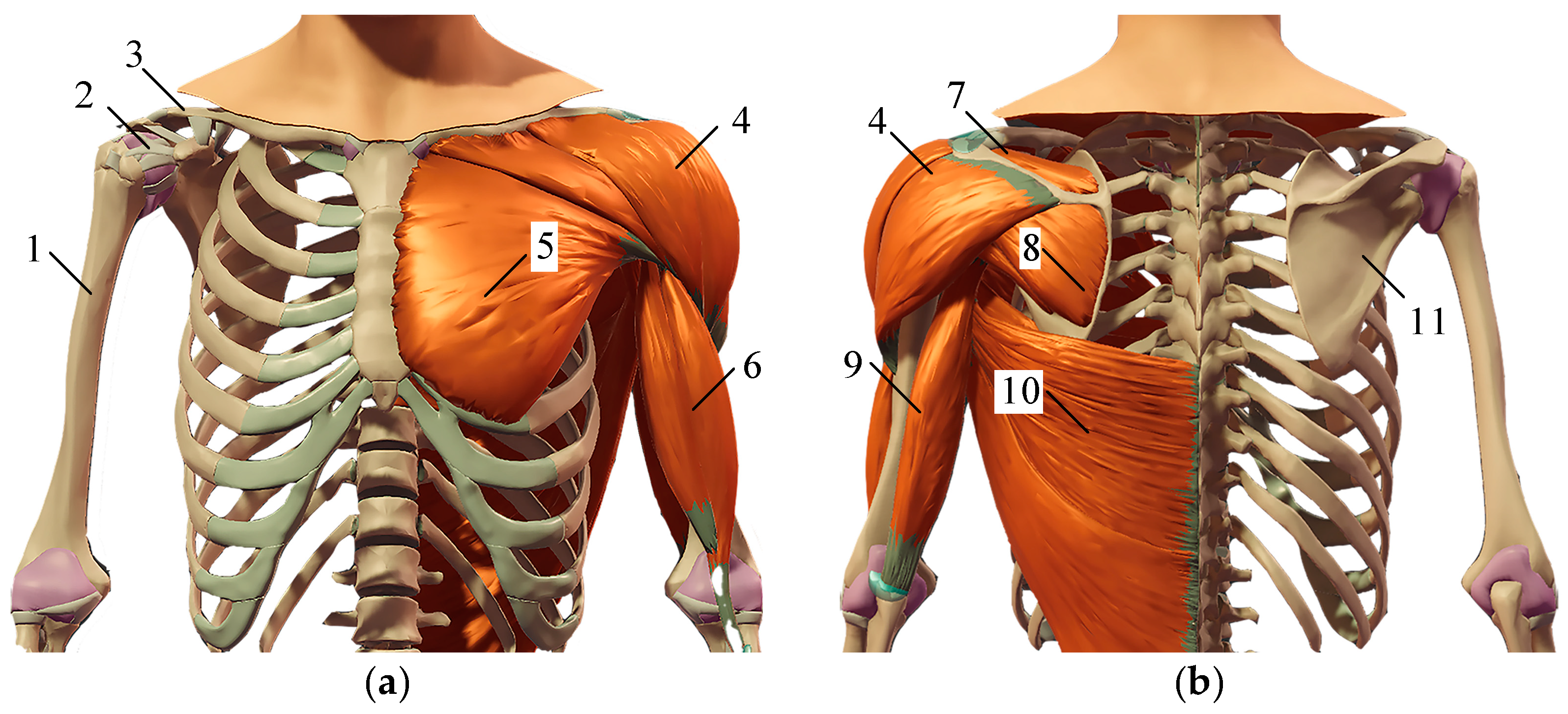
As shown in Figure 1, the human shoulder joint is composed of the humerus, clavicle, and scapula and is a typical ball-and-socket joint. As the joint with the largest range of human motion, the shoulder joint has three degrees of rotational freedom, namely flexion and extension, abduction and adduction, and internal rotation and external rotation.
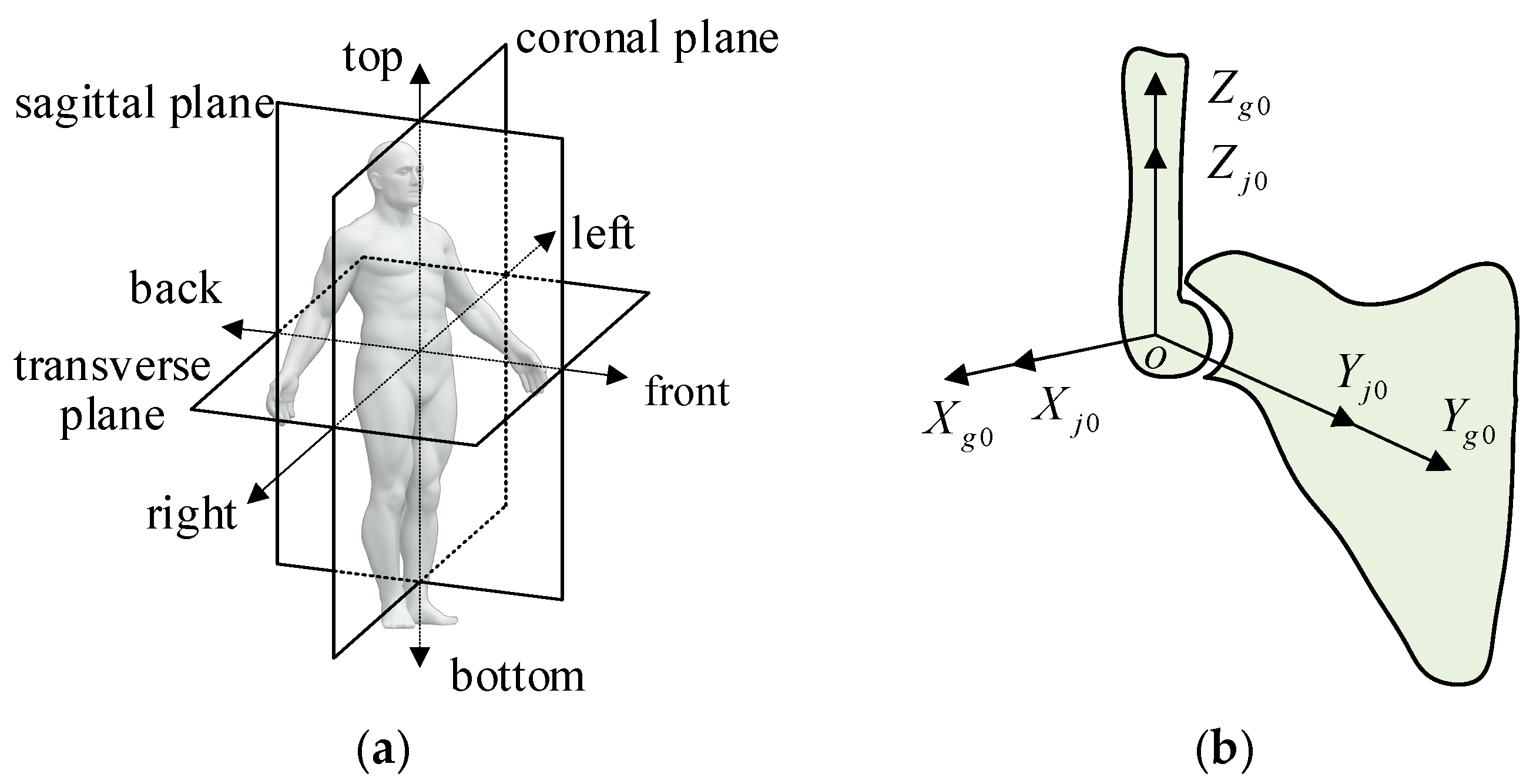
The three reference planes in human anatomy are shown in Figure 2a, and their names and features are as follows: sagittal plane—cutting the human body into the left and right parts; coronal plane—cutting the human body into the front and back parts; and transverse plane—cutting the human body into the upper and lower parts. A fixed coordinate system o - X j 0 Y j 0 Z j 0 ( J 0 ) connected to the scapula and a moving coordinate system o - X g 0 Y g 0 Z g 0 ( G 0 ) connected to the humerus on the shoulder are established, as shown in Figure 2b. Among them, the Z j 0 axis perpendicular to the transverse plane points upward, and the Y j 0 axis perpendicular to the coronal plane points forward.
When the Z Y Z Euler angle with α , β , and γ as the attitude angle parameters is used, the corresponding rotation matrix is as follows:
R G 0 J 0 = c α c β c γ s α s γ c α c β s γ s α c γ c α s β s α c β c γ + c α s γ s α c β s γ + c α c γ s α s β s β c γ s β s γ c β
If the length of the humerus is 1, the coordinates of the end point P of the humerus in J 0 are as follows:
P J 0 = R G 0 J 0 P G 0 = c α s β s α s β c β T
Yang et al. used the Xsens MVN motion capture system to measure the motion range of the human shoulder joint and obtained the following relationship [35]:
α max = 120 12 9 β 90 , β 0 , 180 α min = 40 + 4 9 β 90 , β 0 , 180
The motion space of the human shoulder joint is obtained from Equations (2) and (3), as shown in Figure 3.

2.2. Prototype Mechanism of the Spherical Hybrid Shoulder Joint

According to the physiological structure of the human body, the humerus and scapula form the rigid skeleton of the shoulder joint, and the ligament tissue is distributed between the humerus, clavicle, and scapula to connect and limit them. The various muscle groups work together to drive and complete the task movements of the shoulder joint.
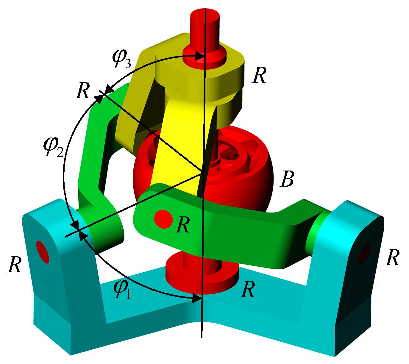
On the basis of the physiological structural characteristics of the human shoulder joint, an RBR-2RRR spherical hybrid shoulder joint prototype mechanism is proposed (R represents the revolute pair and B represents the ball cage joint [36]), as shown in Figure 4. The rigid skeleton of the shoulder joint is equivalent to the rigid components in the mechanism, the connection effect of ligaments is equivalent to the connection relationship between the kinematic pairs, and the collaborative driving of muscle groups is equivalent to the hybrid driving layout between the various limbs of the mechanism. The DOF of this mechanism is three rotational DOFs, where the spin motion of the output rod is driven by the RBR central limb and the spatial two-dimensional swing of the output rod is driven by two RRR side limbs.
The structural parameters of the mechanism are φ 1 , φ 2 , φ 3 , and n , where φ 1 is the angle between the first axis of the limb and the normal of the fixed platform; φ 2 is the angle between the first and second axes of the same limb; φ 3 is the angle between the second and third axes of the same limb; and n is the angle between the projections of the first axes of the two limbs on the fixed platform. During assembly, it is necessary to ensure that the axes of the six revolute pairs intersect at one point and coincide with the rotation center of the ball cage joint.
The advantages of the proposed RBR-2RRR spherical hybrid bionic shoulder joint prototype mechanism are as follows: (1) Each driving input directly acts on the output end, and each driving device does not have to bear the weight of the other driving devices, resulting in a higher utilization rate of the driving torque. (2) Each driving device can be arranged close to the fixed platform to reduce the end load and improve the dynamic performance. (3) The central transmission limb is a constant-speed transmission chain with simple motion control. In addition, the central transmission limb can also support the moving platform for external force unloading and improve the linear displacement stiffness of the mechanism. (4) The normal rotation of the mechanism around the platform is not restricted, which can further improve the normal rotation range of the shoulder joint mechanism around the platform. (5) The added central transmission limb improves the spatial utilization of the central area of the mechanism and reduces the spatial volume of the mechanism (compared with the 3-RRR configuration).

2.3. Verification of Linear Displacement Stiffness Improvement

On the basis of the ANSYS static analysis module, the deformation response of the RBR-2RRR mechanism and the 3-RRR mechanism to the same load is compared to verify that the proposed RBR-2RRR mechanism can improve the linear displacement stiffness of the spherical mechanism.
In the modeling stage, the structural parameters φ 1 , φ 2 , φ 3 , and n of the RBR-2RRR mechanism are 80 ° , 76 ° , 76 ° , and 120 ° , respectively. The 3-RRR mechanism adopts the second set of structural parameters optimized for stiffness in Table 1 of [33]. Specifically, the angle between adjacent revolute pairs is 90°, and the angle between the revolute pairs’ axes on the moving platform and the fixed platform and the normal of the platform is 60°. The width and thickness of the limbs and the rotation shaft radius of the revolute pair are the same in the two mechanisms.
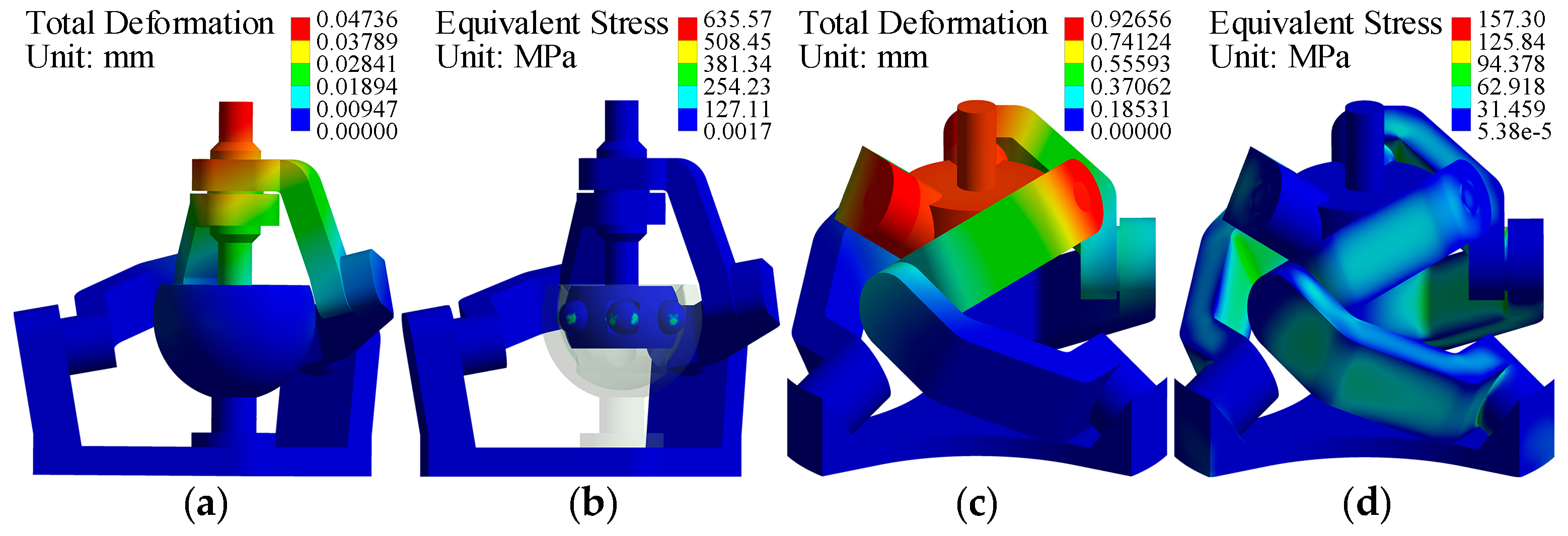
The settings in the ANSYS static analysis module are as follows: the materials for all components are aluminum alloy, except for the outer race, inner race, steel ball, cage, and output rod in the ball cage joint, which are 42CrMo, 42CrMo, GCr15, 20CrMnTi, and structural steel, respectively. The starting revolute pair of each limb chain in the two mechanisms is bound to the fixed platform, and the contact between the other rotating pairs is set to not be separated. The contact between the inner and outer surfaces of the cage is set to be frictionless, and the contact between the steel ball and the inner and outer raceways of the ball cage joint is set to be friction contact with a friction coefficient of 0.1. The unit size is 2 mm, and automatic mesh generation is performed. During the simulation process, it was found that the 3-RRR mechanism first reached the maximum allowable stress value (160 MPa) of the aluminum alloy under a vertical load of 1500 N. Therefore, based on a vertical load of 1500N, the deformation response of the two mechanisms to the same load is compared.
The simulation results show that under a vertical load of 1500 N, the maximum stress value of the RBR-2RRR mechanism (Figure 5b) is 635.57 MPa, which occurs at the position where the steel ball contacts the raceway. The maximum stress value of the 3-RRR mechanism (Figure 5d) is 157.30 MPa, which occurs on the contact plane between the two links. In the ball cage joint, the allowable contact stress between the steel ball and the raceway can reach 3000 MPa [37]. Therefore, although the maximum stress value of the RBR-2RRR mechanism is greater than that of the 3-RRR mechanism, it is much smaller than the allowable contact stress value between the steel ball and the raceway. Therefore, the stress state of the RBR-2RRR mechanism is safe. On the other hand, although the maximum stress value of the 3-RRR mechanism is small, it is close to the maximum allowable stress value of the material, so the stress state of the 3-RRR mechanism is now dangerous. Meanwhile, compared to the 3-RRR mechanism, the force transmission of the RBR-2RRR mechanism mainly occurs on the central limb, and the load force on the side limb of the mechanism is very small, achieving external force unloading. Overall, the RBR-2RRR mechanism exhibits better stress performance.
Comparing the deformation diagrams of the RBR-2RRR mechanism (Figure 5a) and the 3-RRR mechanism (Figure 5c), it can be seen that under approximately the same geometric parameters of the components, for the same vertical load, the deformation of the RBR-2RRR mechanism (0.047 mm) is much smaller than that of the 3-RRR mechanism (0.927 mm). This indicates that the RBR-2RRR mechanism can reduce the deformation displacement of the motion platform under external loads and improve the linear displacement stiffness of the spherical mechanism, consistent with the configuration expectation.

3. Kinematic Analysis

3.1. Forward Kinematics and Simulation Verification

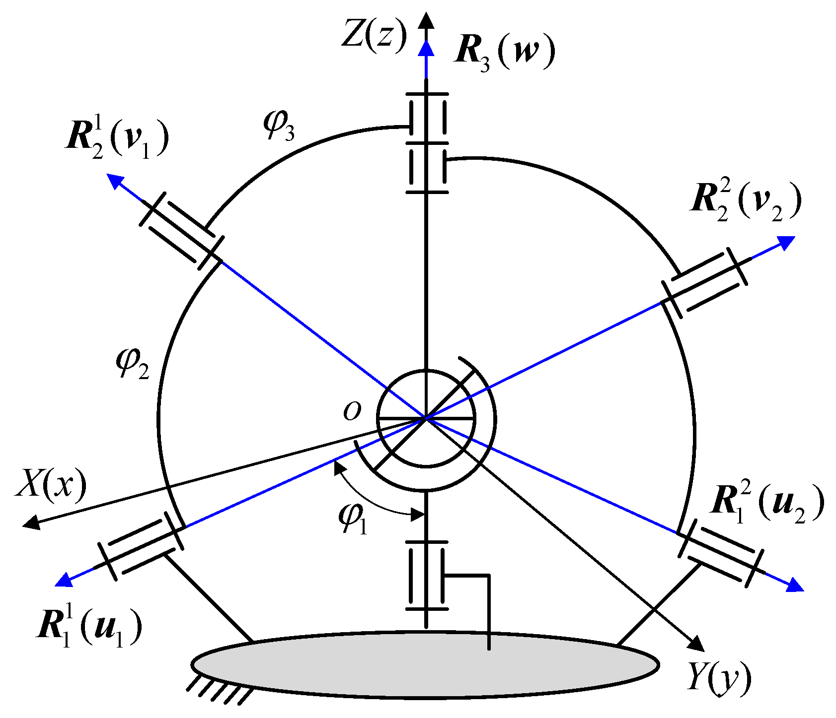
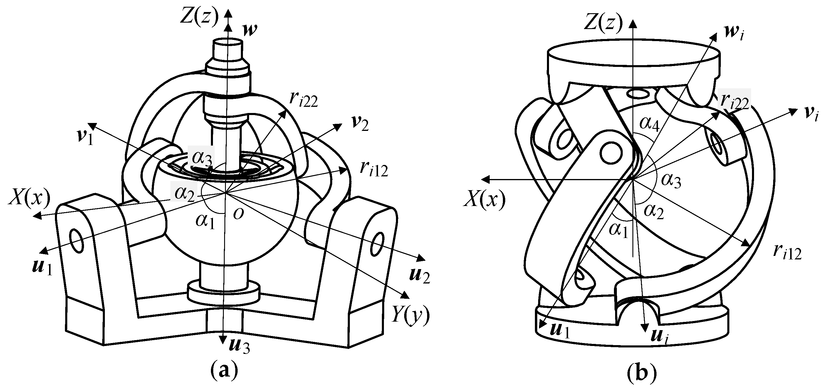
As shown in Figure 6, we established the coordinate systems o-XYZ and o-xyz with the rotation center of the mechanism serving as their origin. The initial orientations of these two coordinate systems are aligned and firmly linked to the fixed platform and the output rod, respectively. The Z axis is perpendicular to the fixed platform and upward, and the X axis is in the plane R 1 1 o Z . R 1 i , R 2 i , and R 3 are the unit direction vectors of each revolute pair (which can also be expressed as u i , v i , and w , respectively), where the superscript i represents the i - th limb, and i = 1, 2. φ 1 is the angle between the limb’s first axis and the fixed platform’s normal. φ 2 is the angle between the first and second axes of the same limb. φ 3 is the angle between the second and third axes of the same limb. In the initial state, the plane R 1 i o R 2 i is coplanar with the Z axis, and R 2 i points upwards.
We set the ZYZ Euler angle parameters of o-xyz relative to o - X Y Z as α , β , and γ . In o - X Y Z , R 1 i , R 2 i and R 3 can be expressed as
R 1 i = u i = R z ( n i ) R y ( π φ 1 ) [ 0   0   1 ] T
R 2 i = v i = R z ( n i ) R y ( π φ 1 ) R z ( θ i ) R y ( φ 2 ) [ 0   0   1 ] T
R 3 = w = R z ( α ) R y ( β ) [ 0   0   1 ] T
where R y ( θ i ) and R z ( θ i ) are the rotation transformation matrices around the y and z axes, respectively. θ i is the mechanism’s input angle. n i is the angle between the plane R 1 i o Z and the plane X o Z , specifically n 1 = 0 , n 2 = 120 .
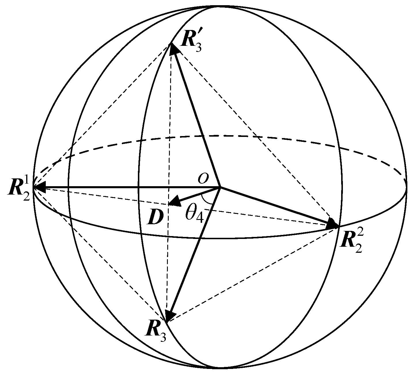
The vectors R 2 1 , R 2 2 , and R 3 in the mechanism are distributed on the same unit sphere, as shown in Figure 7. Due to the same structural parameters of the two limbs, the triangle R 2 1 R 2 2 R 3 is an isosceles triangle, and the midpoint D of R 2 1 R 2 2 is the perpendicular foot of the line segment D R 3 on the line segment R 2 1 R 2 2 . Obviously, when the input angle θ i of the two limbs is known, the spatial vectors of R 2 1 and R 2 2 are uniquely determined. At this time, there are two points that satisfy the condition that both R 2 1 o R 3 and R 2 2 o R 3 are φ 3 , located on both sides of plane R 2 1 o R 2 2 , denoted as R 3 and R 3 .
According to Equation (5), the values of R 2 1 and R 2 2 can be obtained. We set them as:
R 2 1 = a 1 b 1 c 1 T ,   R 2 2 = a 2 b 2 c 2 T
Without considering singular configurations ( R 2 1 , R 2 2 , and R 3 coplanar or R 2 1 and R 2 2 overlapping), in the right-angled triangle R 2 1 R 3 D , according to the Pythagorean theorem, we obtain
D R 3 = R 2 1 R 3 2 0.25 R 2 1 R 2 2 2
where R 2 1 R 2 2 = a 2 a 1 2 + b 2 b 1 2 + c 2 c 1 2 , R 2 1 R 3 = R 2 2 R 3 = 2 2 cos φ 3 .
Solving Equation (8), we obtain
D R 3 = 2 2 cos φ 3 0.25 a 2 a 1 2 + b 2 b 1 2 + c 2 c 1 2
If the spatial vectors of R 2 1 and R 2 2 are known, the spatial coordinates, length, and unit vector of point D can be obtained. Specifically,
D = 0.5 R 2 1 + R 2 2 = 0.5 a 1 + a 2 b 1 + b 2 c 1 + c 2 T
D = 0.5 a 1 + a 2 2 + b 1 + b 2 2 + c 1 + c 2 2
U D = D / D = a 1 + a 2 b 1 + b 2 c 1 + c 2 T / a 1 + a 2 2 + b 1 + b 2 2 + c 1 + c 2 2
Obviously, the unit vector U R 2 1 R 2 2 of R 2 1 R 2 2 is the normal vector of the plane O D R 3 , so the unit vector U D of D can be rotated clockwise around the U R 2 1 R 2 2 axis by θ 4 to coincide with R 3 and counterclockwise by θ 4 to coincide with R 3 . Thus, the relationship between the attitude angles α and β of the mechanism and the input angles θ 1 and θ 2 is established.
In the spatial right-angled triangle O D R 3 , according to the law of cosines, we obtain
cos D O R 3 = cos θ 4 = D 2 + R 3 2 D R 3 2 / 2 D R 3
Solving Equation (13), we obtain
θ 4 = arccos ( 2 cos φ 3 / a 1 + a 2 2 + b 1 + b 2 2 + c 1 + c 2 2 )
The unit vector U R 2 1 R 2 2 can be obtained from R 2 1 and R 2 2 :
U R 2 1 R 2 2 = a 2 a 1 b 2 b 1 c 2 c 1 T / a 2 a 1 2 + b 2 b 1 2 + c 2 c 1 2
Assuming U R 2 1 R 2 2 = k x k y k z T , the transformation matrix for rotating around the U R 2 1 R 2 2 axis is
R k ( θ ) = k x k x ( 1 c θ ) + c θ k x k y ( 1 c θ ) k z s θ k x k z ( 1 c θ ) + k y s θ k x k y ( 1 c θ ) + k z s θ k y k y ( 1 c θ ) + c θ k y k z ( 1 c θ ) k x s θ k x k z ( 1 c θ ) k y s θ k y k z ( 1 c θ ) + k x s θ k z k z ( 1 c θ ) + c θ
From the previous analysis, it can be concluded that after rotation around the U R 2 1 R 2 2 axis, U D can coincide with R 3 or R 3 , that is
R 3 = R k ( θ 4 ) U D = a 3 b 3 c 3 T R 3 = R k ( θ 4 ) U D = a 4 b 4 c 4 T
Combining Equations (6) and (17), we obtain
α 1 = arctan ( b 3 / a 3 ) β 1 = arccos c 3   or   α 2 = arctan ( b 4 / a 4 ) β 2 = arccos c 4
The central limb has no relative rotation between the output rod and the input rod. Therefore, the output rod needs to rotate α around the z-axis during the last attitude transformation to counteract the influence of rotating α around the z-axis first when using the ZYZ Euler angle transformation. The result is
γ = α + θ 3
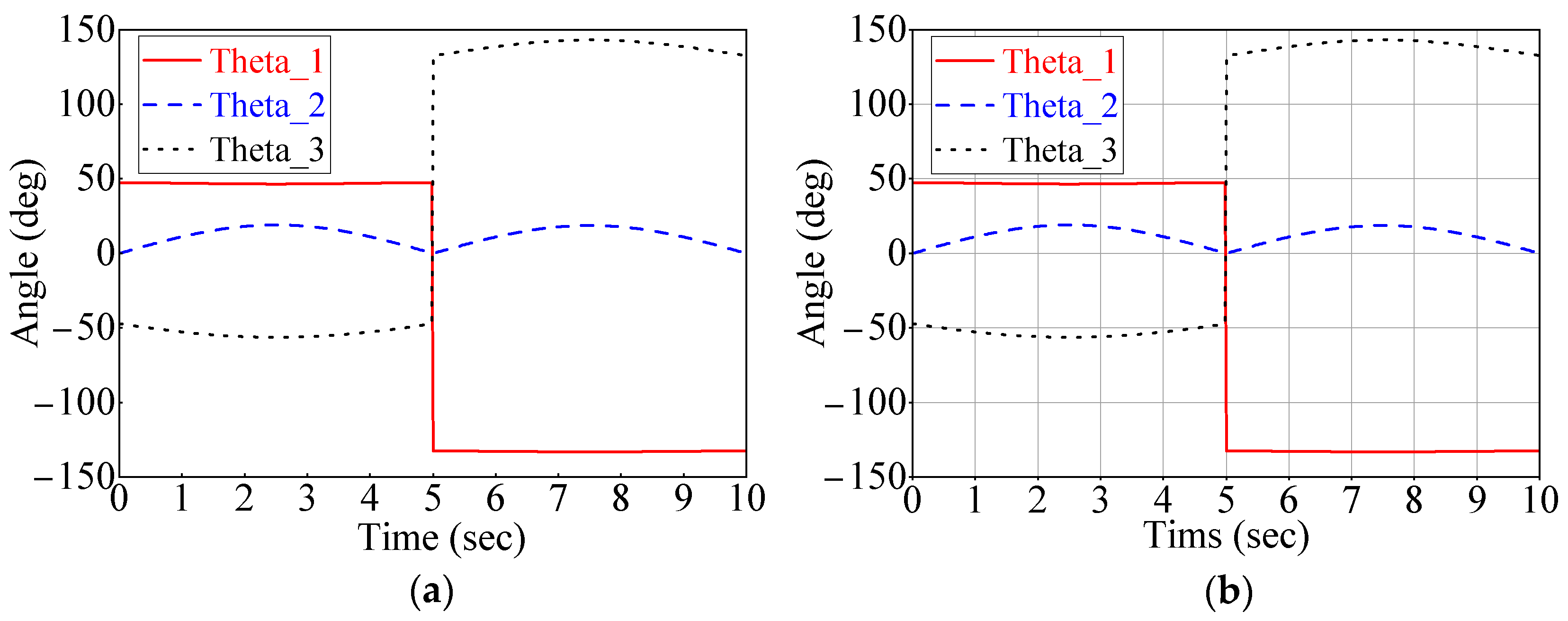
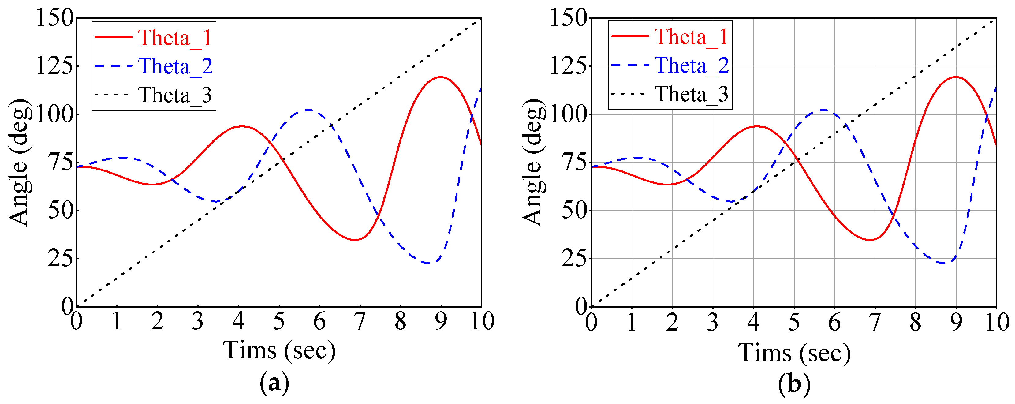
We established a simulation model in ADAMS with the structural parameters φ 1 , φ 2 , φ 3 , and n set as 80 ° , 76 ° , 76 ° , and 120 ° , respectively. Given the input angles θ 1 = 10 sin ( π t / 5 ) , θ 2 = 20 sin ( π t / 5 ) , and θ 3 = 10 sin ( π t / 5 ) of each limb, the simulation time was 10 s, and the variation curve of the end effector attitude angle of the mechanism output rod was obtained as shown in Figure 8b. Meanwhile, the theoretical curves of the end effector attitude angle of the output rod can be obtained in MATLAB using Equations (18) and (19), as shown in Figure 8a. The numerical values and trends of the theoretical curve and simulation curve are the same, which proves the correctness of the positive solution model.

3.2. Inverse Kinematics and Simulation Verification

From the geometric relationship between the revolute pair R 2 i and R 3 , we obtain
R 2 i ( R 3 ) T = cos φ 3
Substituting Equations (5) and (6) into Equation (20), we obtain
θ i = 2 arctan a ± ( a 2 + b 2 c 2 ) b + c   ,   i = 1 , 2
where
a = s ( α n i ) s β s φ 2 , b = s φ 2 ( c ( α - n i ) s β c φ 1 + c β s φ 1 ) , c = c φ 2 ( c β c φ 1 c ( α n i ) s β s φ 1 ) + c φ 3 .
Meanwhile, from Equation (19), we obtain
θ 3 = α + γ
Using the forward kinematics simulation model, we set the attitude angle parameter α of the output rod as 2 π t / 5 , β as π t / 36 , and γ as 19 π t / 60 . The simulation time was set to 10 s, and the simulation curve of the input angle θ i is shown in Figure 9b. Meanwhile, the theoretical curves of the mechanism input angle θ i can be obtained in MATLAB using Equations (21) and (22), as shown in Figure 9a. The numerical values and trends of the theoretical and simulation curve are the same, which verifies the correctness of the inverse kinematics solution.

3.3. Velocity Jacobian Matrix

The Jacobian matrix is a generalized transmission ratio of input joint velocities and end-effector velocities, which varies with the pose of the mechanism.
Taking the derivative of Equations (20) and (22), we obtain:
A 11 A 12 0 A 21 A 22 0 1 0 1 α ˙ β ˙ γ ˙ = B 11 B 22 1 θ ˙ 1 θ ˙ 2 θ ˙ 3   or   A θ ˙ α β γ = B θ ˙
where
A i 1 = s β ( s ( α n i ) ( c φ 1 c θ i s φ 2 + s φ 1 c φ 2 ) + c ( α n i ) s θ i s φ 2 ) , i = 1, 2
A i 2 = c β ( s ( α n i ) s θ i s φ 2 c ( α n i ) ( c φ 1 c θ i s φ 2 + s φ 1 c φ 2 ) ) + s β ( s φ 1 c θ i s φ 2 c φ 1 c φ 2 ) , i = 1, 2
B i i = s φ 2 ( s β ( c ( α n i ) c φ 1 s θ i + s ( α n i ) c θ i ) + c β s φ 1 s θ i ) , i = 1, 2
To this end, the velocity Jacobian matrix of the mechanism is expressed as follows:
J = Φ A 1 B ;   Φ = 0 s α c α s β 0 c α s α s β 1 0 c β
where Φ is the transformation matrix between the ZYZ Euler angle rates and angular velocities.

4. Structural Parameter Optimization

On the basis of the kinematic analysis results, the structural parameters of the prototype mechanism are optimized with the workspace and singularity as constraints and the maximization of the global condition index and global dynamic condition index as the optimization objective to achieve better mechanism performance.

4.1. Constraint Conditions

The values of the structural parameters need to meet certain constraints to ensure that the workspace of the bionic shoulder joint prototype mechanism meets expectations and that there are no singular configurations. The following analyzes the conditions that structural parameters need to meet from the perspectives of workspace and singularity.

4.1.1. Workspace Analysis

The RBR-2RRR SHM consists of two RRR side limbs and one RBR central limb, and its theoretical workspace is the intersection of the three limb workspaces, namely
W T = W 1 W 2 W c
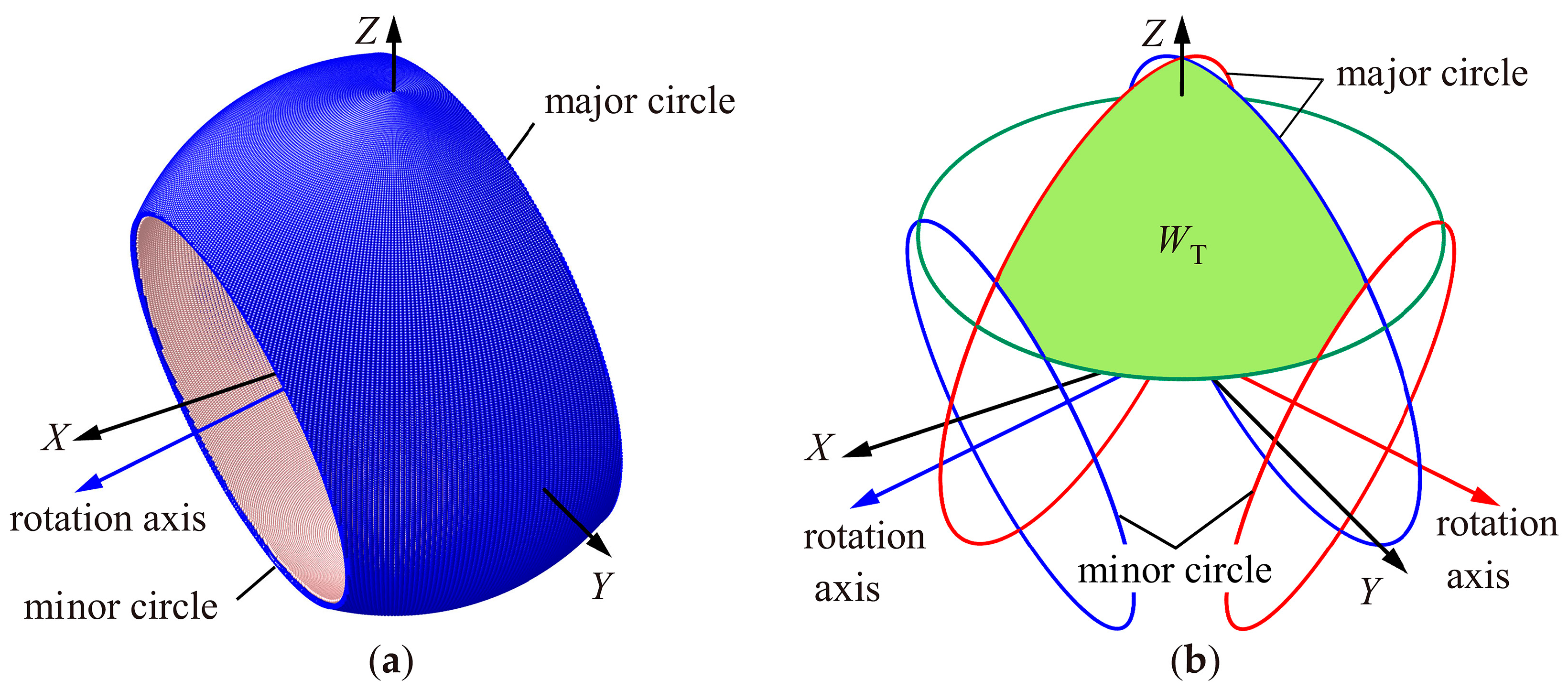
The workspace of the RBR limb is a spherical crown with a central angle 2 β 0 . The workspace of any RRR limb is a spherical frustum, as shown in the blue area in Figure 10a. The spherical frustum can be regarded as a unit ball intercepted by a set of parallel planes. The intersection lines between the unit ball and the two cross-sections are the minor circle and the major circle. The reachable points of the RRR limb output point are distributed between the minor circle and the major circle. The physical meaning of the minor circle is the motion trajectory obtained by the end point rotating around the starting axis of the RRR limb when it is folded in a coplanar fashion, and the physical meaning of the major circle is the motion trajectory obtained by the end point rotating around the starting axis of the RRR limb when it is unfolded in a coplanar fashion. According to Equation (25), the theoretical workspace W T of the RBR-2RRR SHM can be obtained by performing an intersection operation on the workspaces of the three limbs, as shown in the green area in Figure 10b.
The workspace of the RBR-2RRR SHM is affected mainly by the swing angle of the central limb. If the theoretical workspace of the mechanism is to be filled with a spherical crown with a central angle 2 β 0 , the workspace of any RRR limb should completely cover the workspace of the central limb. Therefore, the structural parameters of the mechanism should satisfy the following:
φ 1 + φ 2 φ 3 π β 0 φ 1 + φ 2 + φ 3 π + β 0

4.1.2. Singularity Analysis

A position posture with zero singular values of the Jacobian matrix is commonly referred to as a singular configuration. At this time, the actual DOFs of the mechanism are not equal to its theoretical DOFs, and there are two situations: one is that the mechanism loses its due DOFs, resulting in the loss of a certain motion function, and the second is that the mechanism has gained additional DOFs. Even if all driving inputs are locked, the mechanism can still move under external forces, causing the mechanism to lose control.
Limb singularity and platform singularity exist in the RBR-2RRR SHM [38]. The condition for limb singularity to occur is that the revolute pairs R 1 i , R 2 i , and R 3 on the same limb chain are coplanar, as shown in Figure 11a,b. At this time, the limb can only generate velocity components perpendicular to the limb plane and cannot generate velocity components in any direction along the limb plane, causing the mechanism to lose its DOF in one direction. The conditions for platform singularity to occur are that R 2 1 , R 3 , and R 2 2 are coplanar, and there are two situations: one is that R 2 1 and R 2 2 are coaxial, as shown in Figure 11c. When the input shafts R 1 1 and R 1 2 of the mechanism are locked, the output rod of the RBR-2RRR mechanism can still rotate around the R 2 1 axis, and the mechanism is in a state of loss control. Another type is R 2 1 and R 2 2 distributed on both sides of R 3 , as shown in Figure 11d. At this time, the mechanism does not have the ability to resist normal direction loads from the R 2 1 o R 2 2 plane.
If there is no limb singularity in the workspace with a central angle of 2 β 0 , a parameter δ 1 can be set to prevent any RRR limb from completely flattening or folding in the desired workspace. The relationships among the structural parameters should be as follows:
φ 1 + φ 2 φ 3 π β 0 δ 1 φ 1 + φ 2 + φ 3 π + β 0 + δ 1
If platform singularity does not occur in a workspace with a central angle of 2 β 0 , the minimum angle between the connecting rods connected to the output rod in the two limbs can be δ 2 , and the maximum angle can be π δ 2 , so that the two connecting rods connected to the output shaft will never be coplanar when moving in the desired workspace. The angle relationship between the limbs is converted into a distance relationship between points R 2 1 and R 2 2 . After sorting, the structural parameters should have the following relationship:
R 2 1 R 2 2 sin φ 3 2 2 cos δ 2 R 2 1 R 2 2 sin φ 3 2 + 2 cos δ 2
Combining Equations (26)–(28), the constraint conditions that the structural parameters need to satisfy are determined as follows:
φ 1 + φ 2 φ 3 π β 0 δ 1 φ 1 + φ 2 + φ 3 π + β 0 + δ 1 R 2 1 R 2 2 sin φ 3 2 2 cos δ 2 R 2 1 R 2 2 sin φ 3 2 + 2 cos δ 2

4.2. Optimization Indicators

4.2.1. Motion Performance Indicators

The most well-known and commonly used motion performance indicators include the local condition index (LCI) and the global condition index (GCI), both of which are defined on the basis of the condition number of the mechanism’s Jacobian matrix.
The condition number can be used to measure the sensitivity of the Jacobian matrix J; that is, the degree to which small changes in the input velocity affect the output velocity. This can be defined as the ratio of the maximum eigenvalue to the minimum eigenvalue of the velocity Jacobian matrix J [39], that is,
κ ( J ) = σ max ( J ) σ min ( J ) , κ ( J ) 1 , +
κ ( J ) should be kept within the smallest possible range. When κ ( J ) = 1, the mechanism has the optimal motion transmission performance, that is, kinematic isotropy. The larger the value of κ ( J ) is, the poorer the stability of the numerical calculations and the accuracy of the kinematic solutions. When κ ( J ) = + , the mechanism is in a singular configuration.
The LCI can be used to measure the local motion dexterity of a mechanism [40], which is defined as the reciprocal of the condition number of the velocity Jacobian matrix, i.e.,
LCI = 1 κ ( J ) ,   LCI 0 , 1
The GCI can be used to evaluate the overall motion dexterity performance of a mechanism within the entire workspace W [25], defined as
GCI = W 1 κ ( J ) d W / W d W ,   GCI 0 , 1
Owing to the large computational cost of integrating 1 / κ ( J ) , discrete methods can also be used in practice [41], namely
GCI = 1 n i = 1 n 1 κ i ( J ) ,   GCI 0 , 1
where n is the total number of points taken in workspace W and κ i ( J ) is the corresponding condition number at the selected point.
The GCI represents the average overall dexterity of a mechanism in the workspace. The larger this value is, the better the overall isotropy of the mechanism, and the higher the dexterity and control accuracy of the mechanism.

4.2.2. Dynamic Performance Indicators

Based on the generalized inertial ellipsoid [42], it can be concluded that the moving platform of the mechanism has a higher acceleration in the direction of the major axis of this ellipsoid and a lower acceleration in the direction of the minor axis. If the lengths of these two axes are the same, the acceleration performance of the mechanism is isotropic.
The maximum and minimum eigenvalues of the inertia matrix M of a mechanical system can characterize the lengths of the inertial ellipsoid’s maximum and minimum principal axes. Therefore, the ratio of the maximum and minimum eigenvalues of the inertia matrix (i.e., the condition number of inertia matrix M ) can be used to reflect the degree of isotropy of the system acceleration, that is,
κ ( M ) = σ max ( M ) σ min ( M ) , κ ( M ) 1 , +
The closer κ ( M ) is to 1, the better the dynamic isotropy of the mechanism. The larger the value of κ ( M ) , the more significant the difference between the maximum and minimum eigenvalues of the inertia matrix, and the higher the dynamic anisotropy of the mechanism. Similar to motion performance indicators, local and global dynamic condition indicators can be defined based on the condition number of the inertia matrix M , as follows.
The local dynamic condition index (LDCI) can be used to measure the local dynamic dexterity of a mechanism [43,44], defined as the reciprocal of the inertia matrix condition number, i.e.,
LDCI = 1 κ ( M ) , LDCI 0 , 1
The global dynamic condition index (GDCI) can be used to evaluate the overall dynamic agility performance of a mechanism within the entire workspace W [43,44]. It is defined as follows:
GDCI = W 1 κ ( M ) d W W d W = 1 n i = 1 n 1 κ i ( M ) ,   GDCI 0 , 1
The GDCI represents the average value of the overall dynamic dexterity of the mechanism in the workspace, and the larger its value, the better the mechanism’s overall isotropy and dynamic flexibility.

4.3. Inertia Matrix of Mechanisms

To use an evaluation index based on the condition number of the inertia matrix for dynamic structural optimization, the inertia matrix of the mechanical system needs to be obtained first. As shown in Figure 12, in order to dynamically optimize the structure of the proposed RBR-2RRR mechanism and compare its dynamic performance with the 3-RRR mechanism, simplified models of the RBR-2RRR and 3-RRR mechanisms were established, mainly composed of simple elements such as equal cross-section circular arc links and cylinders (relevant structural dimensions are shown in Appendix A), and the inertia matrix of the mechanism was obtained by solving the kinetic energy equation of the mechanism.
The RBR-2RRR and 3-RRR mechanisms both contain two side limbs, with the difference being that (a) the third limb of the RBR-2RRR mechanism is the central transmission chain, while the third limb of the 3-RRR mechanism remains the RRR chain, and (b) the moving platform of RBR-2RRR mechanism is the output rod, and the moving platform of 3-RRR mechanism is a cylindrical platform. The inertia matrix of the system is solved using RBR-2RRR as the object. Assuming that limb i is composed of a lower link L i 1 and an upper link L i 2 , the mass and angular velocity of the link L i , j are m i j and ω i j , respectively. From the fixed platform to the moving platform, the unit vectors of the axis in limb i are u i , v i , and w i , respectively, and the angles are θ i , θ i 2 , and θ i 3 , respectively.

4.3.1. The Kinetic Energy of Side Limbs

In the side limbs, the relationship between the angular velocity of each axis and the angular velocity ω of the moving platform is as follows:
ω = θ ˙ i u i + θ ˙ i 2 v i + θ ˙ i 3 w i
To eliminate θ i and θ i 3 , we multiply the normal vectors u i × w i of u i and w i on both sides of the equal sign in Equation (37), and we obtain:
θ ˙ i 2 = ( u i × w i ) T ( u i × w i ) v i ω = ( u i × w i ) T ( u i × w i ) v i J θ ˙ = λ i 2 θ ˙
where ω = [ ω x ω y ω z ] T is the angular velocity of the moving platform, while θ ˙ = [ θ ˙ 1 θ ˙ 2 θ ˙ 3 ] T is the input angular velocity of the mechanism. λ i 2 is the mapping matrix from the joint input angle θ i to the joint rotation angle θ ˙ i 2 .
The angular velocity ω i 2 of the link L i 2 can be expressed as
ω i 2 = θ ˙ i u i + θ ˙ i 2 v i
By substituting Equation (38) into Equation (39) and organizing it into a matrix form, we obtain:
ω i 2 = θ ˙ i u i + θ ˙ i 2 v i = U i θ ˙ + v i λ i 2 θ ˙ = J i 2 θ ˙
where J i 2 is the mapping matrix from the joint input angle θ i to the angular velocity ω i 2 . U i is the conditional judgment matrix, specifically
U 1 = [ u 1 0 0 ] ,   U 2 = [ 0 u 2 0 ] ,   U 3 = [ 0 0 u 3 ]
Furthermore, the kinetic energy of the side limb i is
K i = 1 2 ω i 1 T I i 1 o ω i 1 + 1 2 ω i 2 T I i 2 o ω i 2 = 1 2 θ ˙ T [ U i T I i 1 o U i ] θ ˙ + 1 2 θ ˙ T [ J i 2 T I i 2 o J i 2 ] θ ˙
where I i 1 o and I i 2 o are the inertia matrices of link L i 1 and link L i 2 in the global coordinate system, respectively. The calculation process is shown in Appendix B.

4.3.2. The Kinetic Energy of the Motion Platform and Central Input Shaft

Although the motion platform shapes of RBR-2RRR and 3-RRR are different, the form of the kinetic energy equation is the same.
Let the two motion platforms be P 1 and P 2 , respectively. If the angular velocity of the moving platform is known to be ω , then its kinetic energy is:
K p i = 1 2 ω p i T I p i o ω p i = 1 2 θ ˙ T [ J T I p i o J ] θ ˙
where J is the forward velocity Jacobian matrix of the mechanism.
Similarly, if the axis of the central input shaft is u 3 , then its kinetic energy is
K 3 = 1 2 ω 3 T I 3 o ω 3 = 1 2 θ ˙ T [ U 3 T I 3 o U 3 ] θ ˙
In summary, the kinetic energy equation of the RBR-2RRR mechanism can be obtained as follows:
K = 1 2 K i + K 3 + K p 1 = 1 2 θ ˙ T [ 1 2 ( U i T I i 1 o U i + J i 2 T I i 2 o J i 2 ) + U 3 T I 3 o U 3 + J T I p 1 o J ] θ ˙
Therefore, the inertia matrix M 1 of the RBR-2RRR mechanism is obtained as follows:
M 1 = J T I p 1 o J + 1 2 ( U i T I i 1 o U i + J i 2 T I i 2 o J i 2 ) + U 3 T I 3 o U 3
Similarly, the inertia matrix M 2 of the 3-RRR mechanism can be obtained as
M 2 = J T I p 2 o J + 1 3 ( U i T I i 1 o U i + J i 2 T I i 2 o J i 2 )

4.4. Optimal Results

4.4.1. Optimization Results of a Single Indicator

The structural parameter vector and variation range to be optimized for RBR-2RRR SHM are as follows:
Λ = n 2 φ 1 φ 2 φ 3 ,   φ 1 , φ 2 , φ 3 30 ° , 120 ° ,   n 2 30 ° , 150 °
The parameters in Λ are discretized in increments of 1; all possible combinations of structural parameters are traversed, and all structural parameter vectors Λ i and their corresponding GCI and GDCI values that satisfy Equation (29) are calculated. The results show that when Λ 1 = 90 ° 90 ° 90 ° 90 ° , the GCI reached its maximum value of 0.7785, with LCI max and LCI min being 0.9956 and 0.5207, respectively. When Λ 2 = 51 ° 73 ° 120 ° 69 ° , the GDCI reached its maximum value of 0.1770, with LDCI max and LDCI min being 0.2219 and 0.0466, respectively.
This result only considers the maximum value of GCI and GDCI as the preferred criterion. In addition, when the parameter φ 1 is not 90 ° , the driving motor of the input shaft can be arranged at a certain inclination angle with the fixed platform, thereby reducing the spatial volume of the mechanism. Starting from this point, on the basis of the calculation results of GCI and GDCI, the recommended structural parameter values and corresponding indicator values for φ 1 values of 80 ° , 85 ° , 90 ° , 95 ° , and 100 ° are given, as shown in Table 1 and Table 2.

4.4.2. Optimization Results of Multiple Indicators

From Section 4.4.1, it can be seen that it is not easy to satisfy the maximum values of two optimization indicators at the same point. Considering the actual situation where the running speed and dynamic characteristics of the bionic shoulder joint are not high, when optimizing structural parameters, the focus is on referring to the GCI, supplemented by the GDCI. Therefore, the obtained structural parameters should meet the following conditions:
GCI Λ 3 0.85 GCI GDCI Λ 3 0.7 GDCI
Based on Equation (49) and the calculated results, recommended structural parameter values and corresponding GCI and GDCI values are given for φ 1 values of 80 ° , 85 ° , 90 ° , 95 ° , and 100 ° , as shown in Table 3.
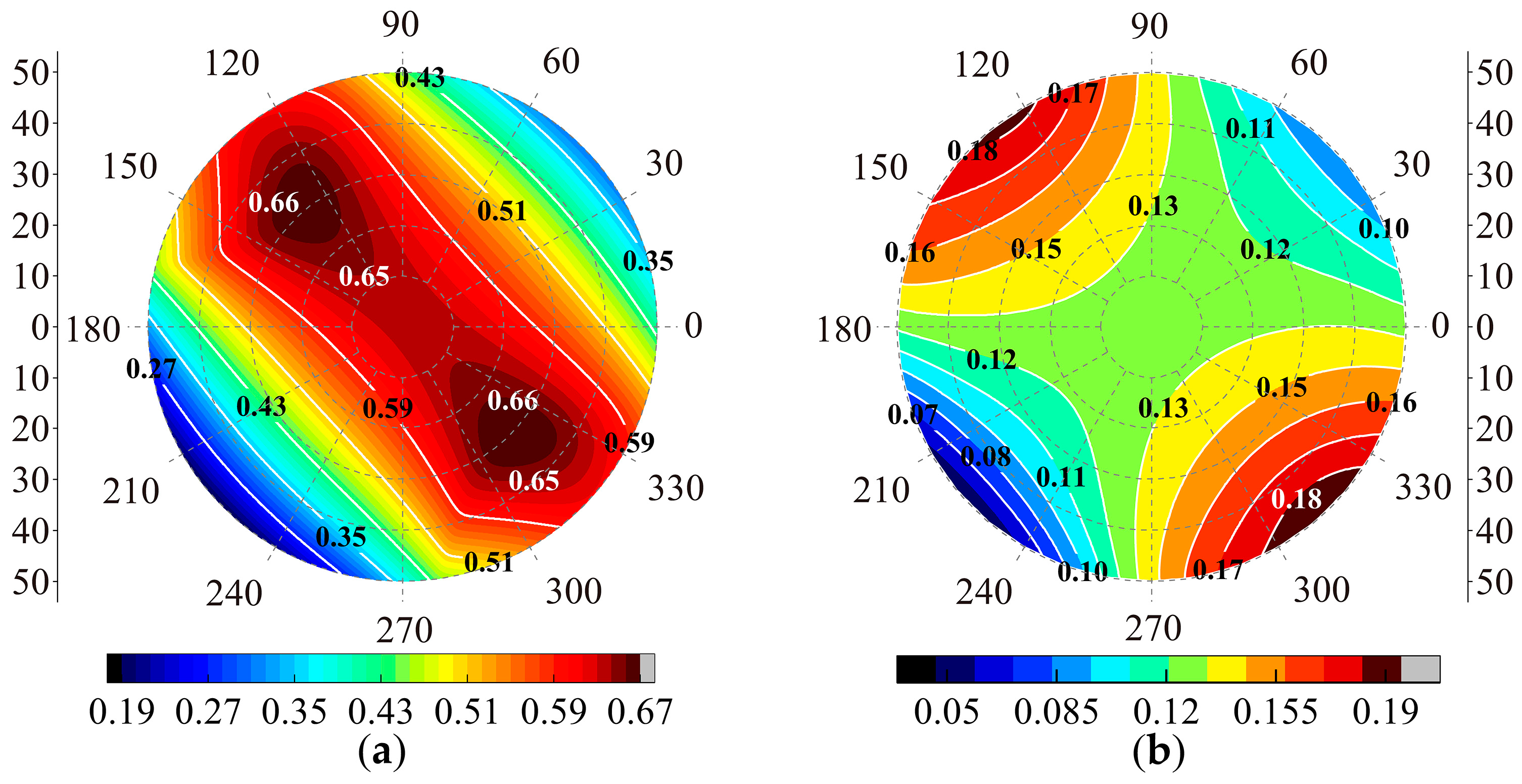
In this paper, accounting for the value of the GCI, GDCI, and the installation space of the driver, the final parameter vector selected is Λ 3 = 85 ° 80 ° 106 ° 82 ° . At this time, the GCI and GDCI of the mechanism are 0.7311 and 0.1317, respectively, and their distribution in the workspace is shown in Figure 13.
Reference [27] optimized the structural parameters of the 3-RRR mechanism based on GCI, and the optimization result of GCI was 0.585. This article uses the structural parameters optimized based on reference [27] and calculates the GDCI value of the 3-RRR mechanism to be 0.2882 using Equation (47). The comparative results show that the motion performance index of the RBR-2RRR mechanism is higher than that of the 3-RRR mechanism, but the dynamic dexterity index is lower than that of the 3-RRR mechanism. This is due to the fact that the side limbs of RBR-2RRR are not evenly distributed in the circumferential direction like the 3-RRR mechanism.

5. Hybrid Bionic Shoulder Joint Mechanism with an Offset Design

The workspace of the bionic shoulder joint prototype mechanism is a spherical crown with a central angle of 100 ° , which still has a certain gap compared with the motion range of the human shoulder joint (Figure 3). To increase the workspace of the proposed bionic shoulder joint mechanism and match its motion range with the human shoulder joint, further improvements will be made to its structure.

5.1. Offset Design of the Spherical Hybrid Bionic Shoulder Joint Mechanism

Although the output rod of the RBR-2RRR SHM method proposed earlier is not restricted in the normal rotation around the moving platform, it is not reflected in the workspace of the mechanism output rod; that is, the contribution of the spin motion of the output rod to the workspace of the mechanism is to some extent masked.
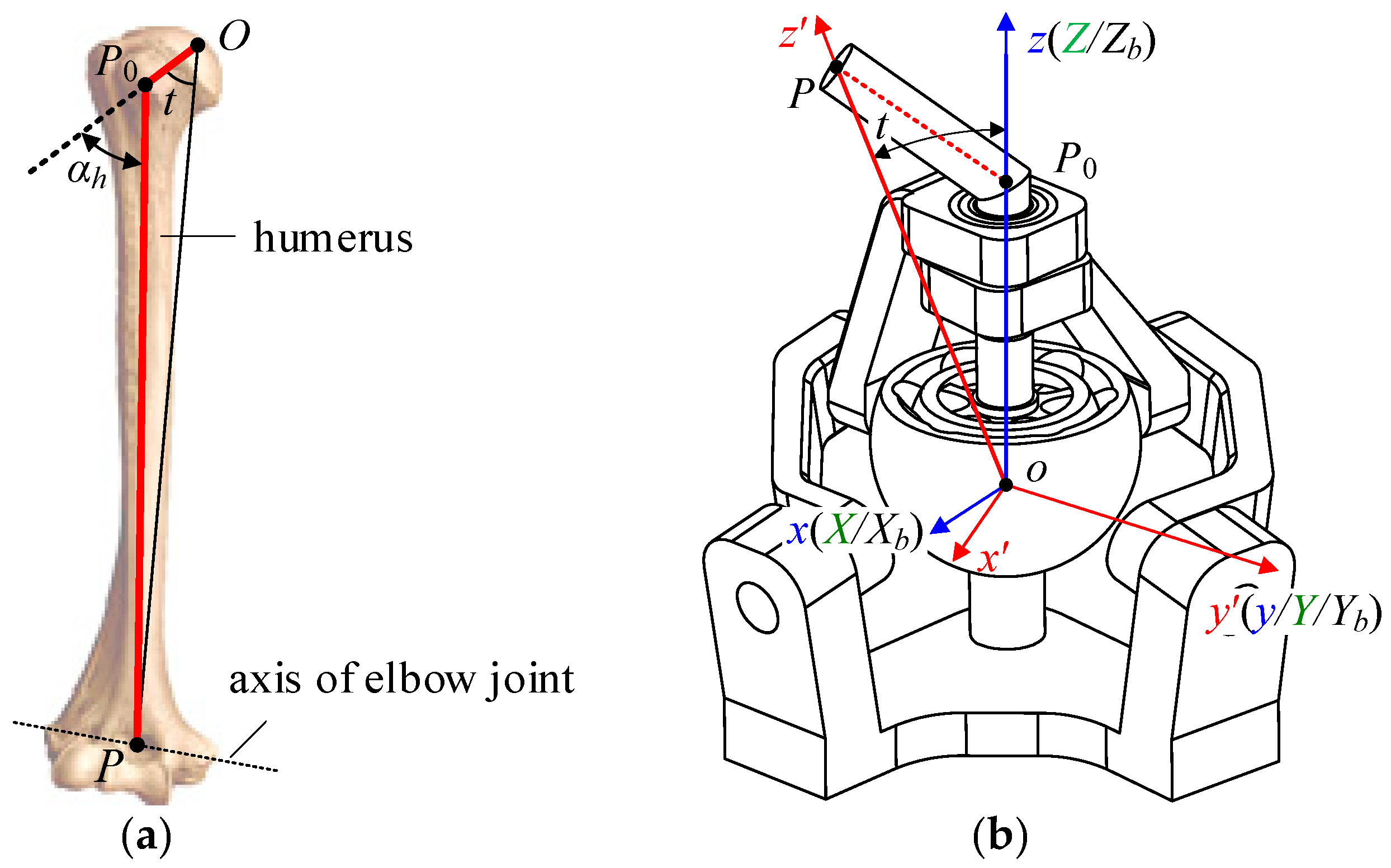
The human shoulder joint is a ball-and-socket joint, but its motion space is significantly larger than that of traditional ball-and-socket joints. Figure 14a shows the structure of the human humerus. The output rod of the human humerus is significantly different from that of the traditional spherical pair: the humeral neck O P 0 and humeral body P 0 P have a certain angle, which is an offset layout.
Compared with the structure of the human humerus, the fundamental reason why the contribution of the spin motion of the RBR-2RRR SHM output rod to the workspace is partially obscured is that the axis of the output rod is always coaxial with the normal of the moving platform. Therefore, Zhou et al. proposed a biomimetic design concept of offset output [8], which involves bending the axis of the output rod in any direction at a certain angle to release the impact of the spin motion of the output rod on the mechanism workspace.
To increase the workspace of the proposed spherical hybrid shoulder joint mechanism, the output rod of the prototype mechanism was bent at a certain angle to deviate its axis from the original output rod axis, resulting in the RBR-2RRR spherical hybrid biomimetic shoulder joint mechanism with an offset design, as shown in Figure 14b.
The actual angle between the output rod axis O P and the straight output rod axis O P 0 is set as the offset angle t , which can be obtained from the trigonometric relationship:
t = θ arcsin ( O P 0 sin θ / O P )
According to human anatomy, the approximate dimensions of the humerus in adult males are O P = 320 mm, O P 0 = 60 mm, and θ 40 ° , 50 ° . By substituting the above parameters into Equation (50), t 41.15 ° , 47.15 ° is obtained. The final output bias angle t of the hybrid bionic shoulder joint is determined to be 45 ° .

5.2. Installation Posture Angle and Spatial Mapping Relationship

The workspace of the obtained spherical hybrid bionic shoulder joint mechanism does not coincide with the workspace of the human shoulder joint in spatial orientation. To match the workspace of the shoulder joint mechanism with that of the human shoulder joint, it is necessary to further determine the installation posture angle of the shoulder joint mechanism’s fixed platform relative to the robot body and establish a parameter mapping relationship between the human workspace and the spherical hybrid shoulder joint prototype mechanism.
To enable problem analysis, the following coordinate system is established, as shown in Figure 14b: (a) The coordinate systems o - X Y Z ( { J } ) and o - x y z ( { G } ) , which are fixedly connected to the hybrid bionic shoulder joint fixed platform and the direct output rod O P 0 , respectively, have the same coordinate axis settings as { J } and { G } in Figure 6. (b) The fixed coordinate system o - X b Y b Z b ( { B } ) , which is fixedly connected to the robot body, is assumed to have its initial pose coinciding with { J } . The posture angle of { J } relative to { B } is the installation posture angle of the hybrid bionic shoulder joint. Let { J } rotate by ψ z 1 , ψ x , and ψ z 2 around the Z b axis, X b axis, and Z b axis to reach the installation posture. In addition, on the basis of the principle of consistency between the mechanism workspace and the human workspace, the initial posture of { B } should coincide with { J 0 } in Figure 2b. (c). The offset rod coordinate system o x y z ( G ) is fixedly connected to the actual output axis O P . Without loss of generality, assuming that the deflection direction occurs within the x o z plane, G can be obtained by rotating G around the y axis by t . The relative attitude relationship between each coordinate system is as follows:
{ J 0 } = { B } Z b , X b , Z b ( ψ z 1 , ψ x , ψ z 2 ) { J } Z , Y , Z ( α , β , γ ) { G } y t { G }
Therefore, if the pose description of a certain point in the coordinate system { J 0 } or { B } is known as α , β , γ ( Z Y Z ) or α , β , γ ( R P Y ) , there is the following spatial mapping relationship:
R Z b ( ψ z 2 ) R X b ( ψ x ) R Z b ( ψ z 1 ) R Z ( α ) R Y ( β ) R Z ( γ ) R y ( t ) [ 0   0   op ] T = R Z b ( α ) R Y b ( β ) R Z b ( γ ) [ 0   0   op ] T or   R Z b ( γ ) R Y b ( β ) R X b ( α ) [ 0   0   op ] T
After ψ z 1 , ψ x , ψ z 2 , and t are determined, the transformation relationship of the attitude angle parameters between the human workspace and the spherical hybrid shoulder joint prototype mechanism can be solved according to Equation (52).
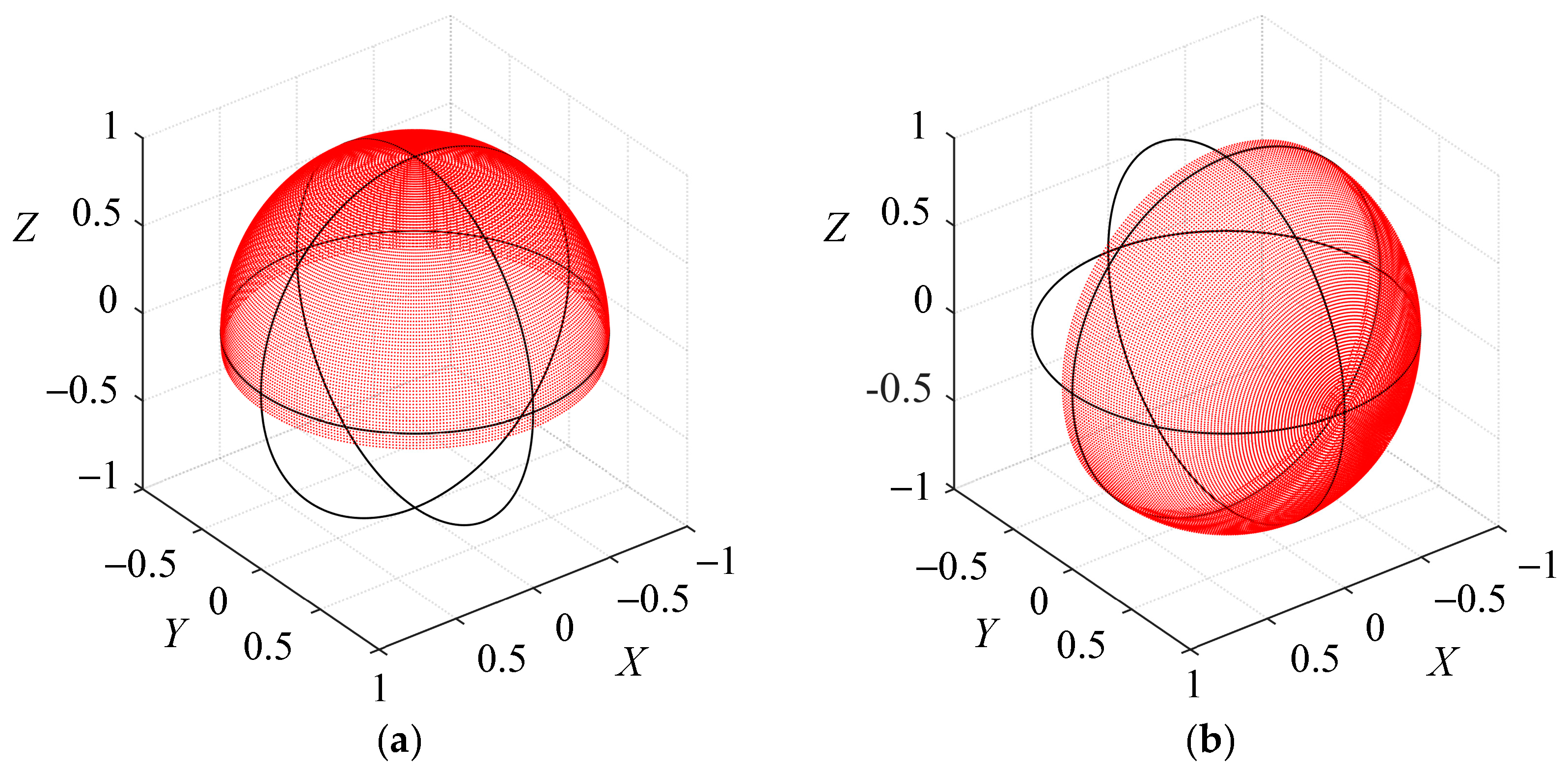
When O P = 1 , t = 45 ° , α , γ [ 0 ° , 360 ° ] , and β [ 0 ° , 50 ° ] , the workspace of the RBR-2RRR spherical hybrid shoulder joint with an offset design can be obtained from Equation (52), as shown in Figure 15a, which is shaped like a spherical crown with a central angle of 190 ° . The workspace of the prototype mechanism is a spherical crown with a central angle of 100 ° . The workspace of the 3-RRR mechanism is a pointed cone with approximately 140 ° of opening and ± 30 ° of torsion [5]. Compared with the prototype mechanism and the 3-RRR mechanism, the working space of the RBR-2RRR SHM with an offset design is significantly increased.
Figure 3 and Figure 15a show that the workspace of the bionic shoulder joint is symmetrical about the y = 0 plane, whereas the active space of the human shoulder joint is symmetrical about the Z j = 0 plane. Therefore, the fixed platform of the bionic shoulder joint can be rotated clockwise around the X b axis by 90 ° first. At this point, the spatial posture of the bionic shoulder joint workspace relative to the coordinate system B is shown in Figure 15b. Furthermore, the initial installation pose angle is determined as
ψ z 1 = 0 , ψ x = 90 ° , ψ z 2 = 0
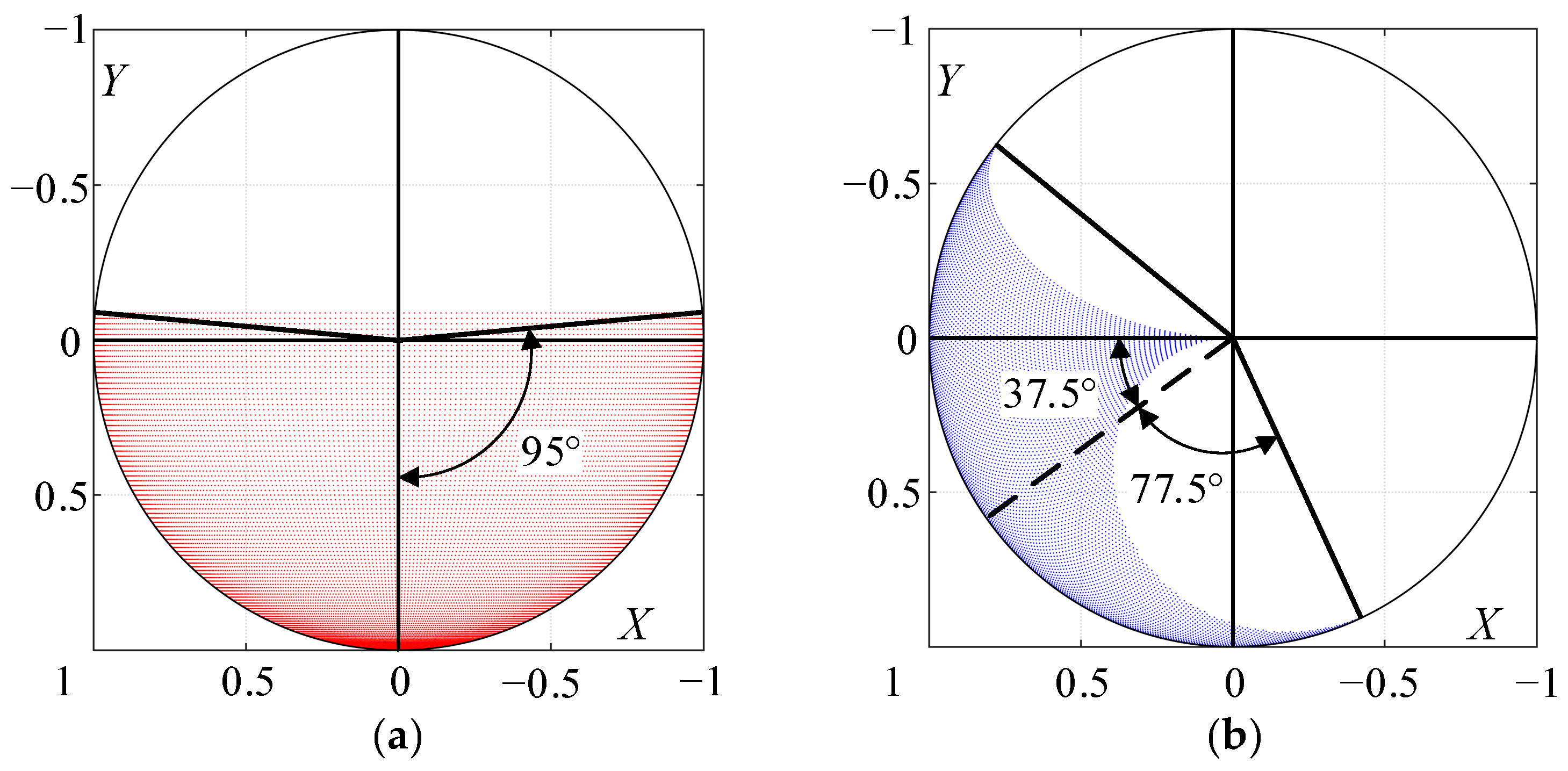
After the first rotation, the workspace of the bionic shoulder joint relative to the coordinate system B and the motion space of the human shoulder joint are both symmetrical about the z = 0 plane. The projections of the two on the X b o Y b plane are shown in Figure 16.
On the basis of the x - y directional views of the two workspaces, the bionic shoulder joint is rotated clockwise around the Z b axis by 52.5 ° to reach the target pose. Therefore, the final installation pose angle is determined as
ψ z 1 = 0 , ψ x = 90 ° , ψ z 2 = 52.5 °
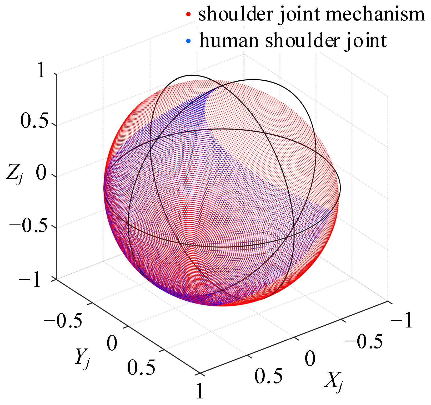
The comparative relationship between the bionic shoulder joint and the human shoulder joint motion space is shown in Figure 17. The results show that the workspace of the offset-designed spherical hybrid shoulder joint mechanism (red area) can fully cover the motion range of the human shoulder joint (blue area), proving that the proposed offset-designed spherical hybrid shoulder joint mechanism meets the workspace requirements.

5.3. Shoulder Joint Action Simulation

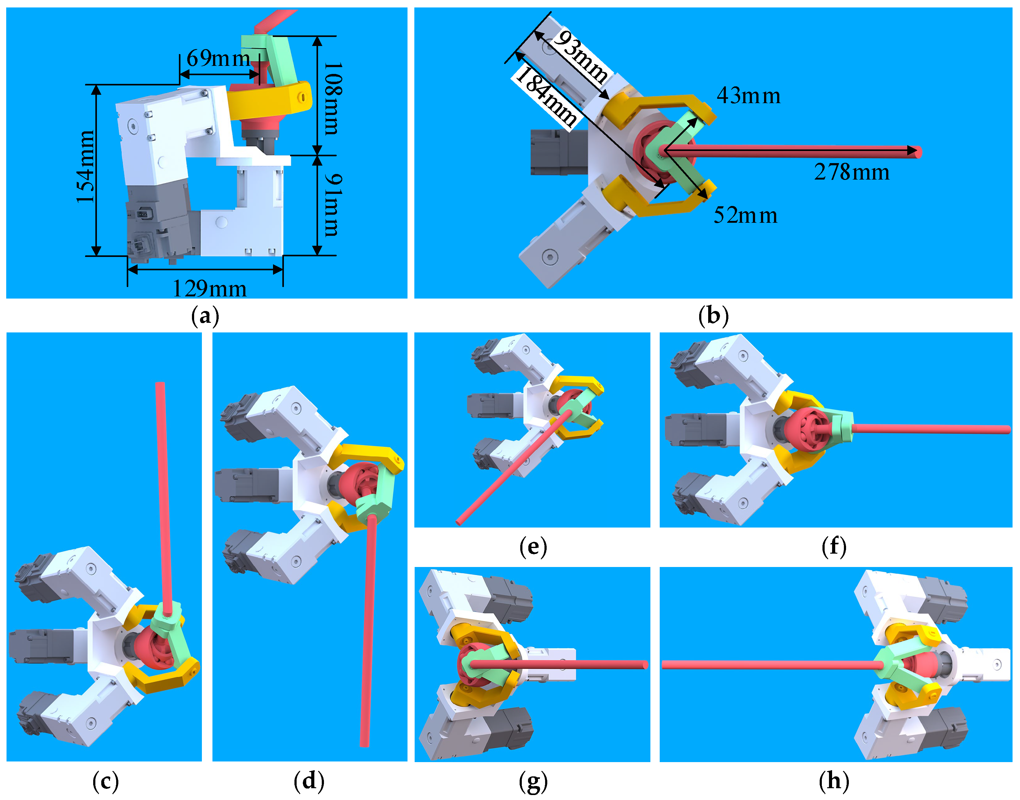
Based on the dimensions of the human glenohumeral joint and the structural parameters and installation posture angle of the spherical hybrid shoulder joint mechanism, a virtual model machine is constructed to simulate human shoulder joint actions. The spatial dimensions and simulated actions of the virtual prototype are shown in Figure 18. The results show that the spherical hybrid shoulder joint mechanism with an offset design proposed in this paper can complete the relevant task actions of the human shoulder joint and meet the configuration expectations.

6. Conclusions

To improve the workspace, linear displacement stiffness, and driving torque utilization of existing humanoid robot shoulder joint mechanisms, an offset-designed RBR-2RRR spherical hybrid bionic shoulder joint configuration (SHBSJC) is proposed, and its structural parameters are optimized. First, the physiological structure of the shoulder joint is biomimetically designed, a prototype mechanism of the RBR-2RRR SHBSJC is proposed, and its kinematics and velocity Jacobian matrix are solved. Based on finite element static analysis, the deformation response of the RBR-2RRR and 3-RRR under the same load is compared to verify that the proposed mechanism meets the configuration expectation of improving linear displacement stiffness. Considering the workspace and singularity, the constraint conditions that the structural parameters of the prototype mechanism need to satisfy are obtained. Using the GCI and GDCI indicators as optimization functions, we obtain recommended and adopted values for structural parameters. The corresponding diagrams of the LCI and LDCI indicate that mechanism’s motion dexterity and dynamic dexterity meet the configuration expectations. To further increase the prototype mechanism’s workspace and match the human shoulder joint’s motion range, an RBR-2RRR SHBSJC with an offset design is proposed, and the offset angle, installation posture angle, and spatial mapping relationship of the mechanism are determined. The results of the workspace comparison and virtual model machine action simulation indicate that the final configuration meets workspace expectations. This research has enriched the design methods and configuration types of shoulder joints in humanoid robots, providing theoretical guidance and engineering application value for the biomimetic design and development of shoulder joints in humanoid robots.
Author Contributions

Conceptualization, S.S. and Y.Z.; methodology, S.S. and Y.Z.; validation, S.S. and F.W.; writing—original draft preparation, S.S. and F.W.; writing—review and editing, S.S. and Y.Z.; project administration, Y.Z.; funding acquisition, S.S. and Y.Z. All authors have read and agreed to the published version of the manuscript.

Funding

This research received no external funding.

Data Availability Statement

The original contributions presented in this study are included in this article; further inquiries can be directed to the corresponding author.

Conflicts of Interest

The authors declare no conflicts of interest.

Appendix A. Model Dimension

The structural parameters of RBR-2RRR and 3-RRR are shown in Table A1 and Table A2, with data in meters. In addition, in the RBR-2RRR mechanism, the material of the central limb is structural steel, while the rest is aluminum alloy. In the 3-RRR mechanism, the material is all aluminum alloy.
Table A1. Structural parameters of RBR-2RRR.
r 11 r 12 r 21 r 22 b h r 31
0.0430.0520.0520.0430.0080.0180.031
r 32 h 31 r 33 r 41 r 42 h 41 h 42
0.0200.0250.010.020.0060.020.045
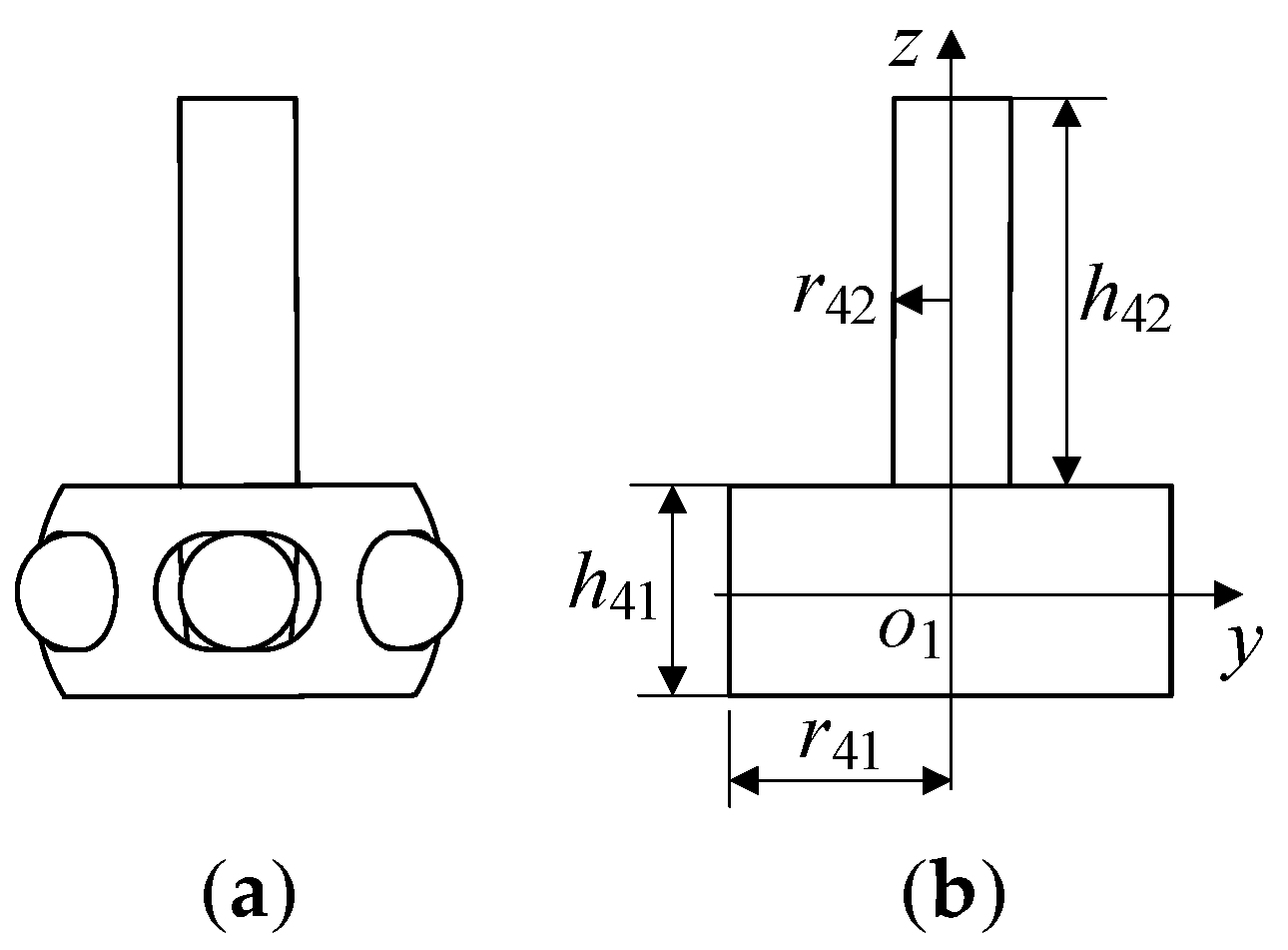
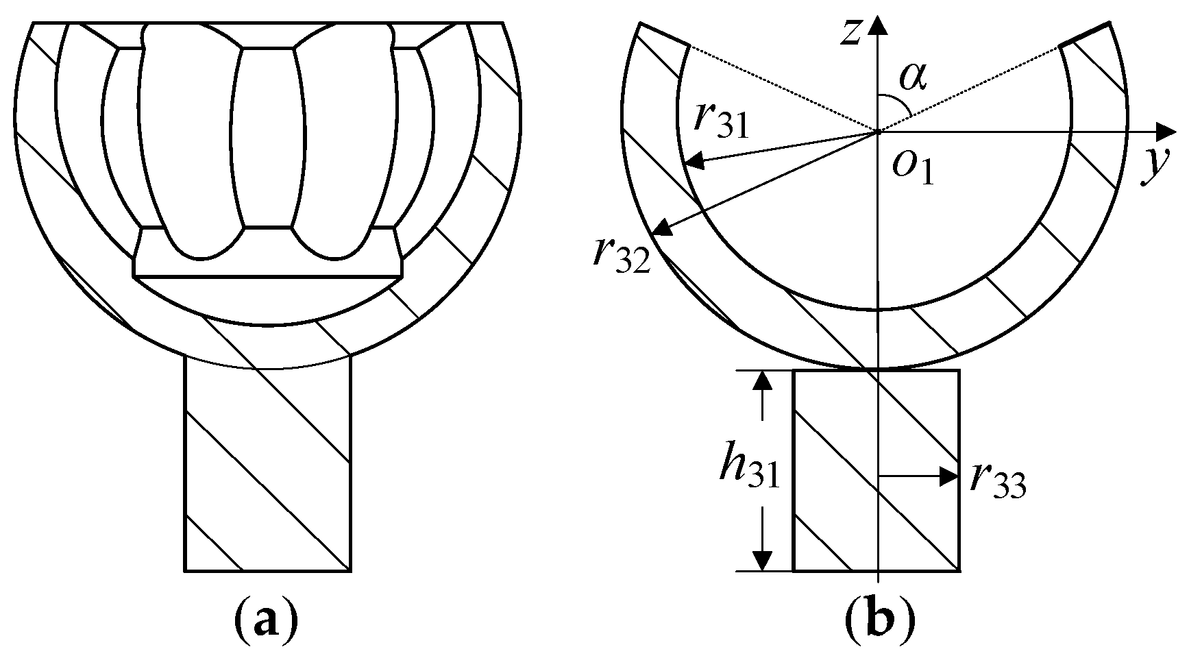
In this table, r i j represents the outer radius of the link j in the limb i, b is the difference between the inner and outer radii of the link, and h is the thickness of the link. The meanings of r 31 , r 32 , h 31 , and r 33 are shown in Figure A2. The meanings of r 41 , r 42 , h 41 , and h 42 are shown in Figure A3.
Table A2. Structural parameters of 3-RRR.
r i 1 r i 2 b h r p 1 h p 1
0.0520.0430.0080.0180.020.008
In this table, r i j represents the outer radius of the link j in the limb i, b is the difference between the inner and outer radii of the link, h is the thickness of the link, r p 1 is the radius of the moving platform, and h p 1 is the thickness of the moving platform.

Appendix B. Mass Moment of Inertia

The components of the RBR-2RRR and the 3-RRR mechanism mainly include rectangular-cross-section circular arc links, the moving platform of the 3-RRR, and the input and output shafts of the RBR-2RRR. The moving platform structure of 3-RRR is relatively simple, so it was not discussed.
(1)
Circular arc link with rectangular cross-section
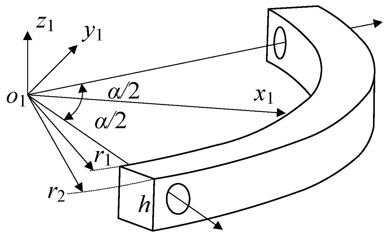
Assuming the inner and outer diameters of the circular arc connecting rod are r 1 and r 2 , the height of the rectangular section is h , the origin o 1 of the coordinate system is located at the intersection of the axis of the circular arc rod, the x axis is located on the angle bisector of the circular arc rod, and the x o 1 y plane is located on the symmetry plane of the rod.
Figure A1. Circular arc link with rectangular cross-section.
Machines 12 00683 g0a1
The inertia matrix of the link to o 1 is
I o 1 = diag [ I x x   I y y   I z z ]
where
I x x = V ρ ( y 2 + z 2 ) d V = α 2 α 2 r 1 r 2 h 2 h 2 ( r 3 sin 2 α + z 2 r ) d z d r d α = ρ h 8 ( r 2 4 r 1 4 ) ( α sin α ) + ρ α 24 h 3 ( r 2 2 r 1 2 )
I y y = V ρ ( x 2 + z 2 ) d V = α 2 α 2 r 1 r 2 h 2 h 2 ( r 3 cos 2 α + z 2 r ) d z d r d α = ρ h 8 ( r 2 4 r 1 4 ) ( α + sin α ) + ρ α 24 h 3 ( r 2 2 r 1 2 )
I z z = V ρ ( x 2 + y 2 ) d V = α 2 α 2 r 1 r 2 h 2 h 2 r 3 d z d r d α = ρ α h 4 ( r 2 4 r 1 4 )
If the rotation transformation matrix of the coordinate system { o 1 } relative to the global coordinate system { o } is known as R , then the inertia matrix of the member to o is
I o = R I o 1 R T
(2)
Input shaft of central limb
The geometric shape of the RBR-2RRR central limb input shaft is shown in Figure A2, which is equivalent to a combination of a hollow circular shell and a cylinder, and this component only rotates around the z axis.
Figure A2. Input shaft of central limb: (a) sectional view of input shaft; (b) equivalent model.
Machines 12 00683 g0a2
To simplify the calculation, α is taken as π / 3 . The inertia matrix of the central limb input shaft relative to o 1 is
I o 1 = diag [ I x x   I y y   I z z ]
where
I z z = I z z 1 + I z z 2 ,   I x x = I y y = 0 ,   I z z 1 = 1 2 ( ρ r 33 2 h 31 ) r 33 2 = 1 2 ρ h 31 r 33 4
I z z 2 = V ρ ( x 2 + y 2 ) d x d y d z = 0 2 π π 3 π r 1 r 2 r 4 sin 4 φ d r d φ d θ = 9 π ρ 20 ( r 32 5 r 31 5 )
(3)
Output shaft of central limb
The geometric shape of the RBR-2RRR central limb output shaft is shown in Figure A3, which is equivalent to a combination of two cylinders.
Figure A3. Output shaft of central limb: (a) side view of output shaft; (b) equivalent model.
Machines 12 00683 g0a3
The inertia matrix of the input axis relative to o 1 is
I o 1 = diag [ I x x   I y y   I z z ]
where
I x x = I y y = ρ π ( 3 r 41 4 h 41 + 3 r 42 4 h 42 + r 41 2 h 41 3 + r 42 2 h 42 3 ) 12 + ρ π r 42 2 ( h 41 + h 42 ) 2 4
I z z = I z z 1 + I z z 2 = 1 2 ρ π ( r 41 3 h 41 + r 42 3 h 42 )

References

  1. Tsagarakis, N.G.; Caldwell, D.G.; Negrello, F.; Choi, W.; Baccelliere, L.; Loc, V.G.; Noorden, J.; Muratore, L.; Margan, A.; Cardellino, A.; et al. WALK-MAN: A High-Performance Humanoid Platform for Realistic Environments. J. Field Robot. 2017, 34, 1225–1259. [Google Scholar] [CrossRef]
  2. Lee, D.-H.; Park, H.; Park, J.-H.; Baeg, M.-H.; Bae, J.-H. Design of an anthropomorphic dual-arm robot with biologically inspired 8-DOF arms. Intell. Serv. Robot. 2017, 10, 137–148. [Google Scholar] [CrossRef]
  3. Lee, J.; Cho, B.-K. Design of 9-DOF humanoid arms inspired by the human’s inner shoulder to enhance versatility and workspace. Robot. Auton. Syst. 2023, 166, 104447. [Google Scholar] [CrossRef]
  4. Gosselin, C.; Angeles, J. The Optimum Kinematic Design of a Spherical Three-Degree-of-Freedom Parallel Manipulator. J. Mech. Transm. Autom. Des. 1989, 111, 202–207. [Google Scholar] [CrossRef]
  5. Gosselin, C.M.; Hamel, J.-F. The agile eye: A high-performance three-degree-of-freedom camera-orienting device. In Proceedings of the 1994 IEEE International Conference on Robotics and Automation, San Diego, CA, USA, 8–13 May 1994; pp. 781–786. [Google Scholar] [CrossRef]
  6. Hou, Y.; Hu, X.; Zeng, D.; Zhou, Y. Biomimetic Shoulder Complex Based on 3-PSS/S Spherical Parallel Mechanism. Chin. J. Mech. Eng. 2015, 28, 29–37. [Google Scholar] [CrossRef]
  7. Hou, Y.; Wang, Y.; Fan, J.; Hu, X.; Zeng, D. Optimization and Bionic Design of 3-PCSS/S Spherical Parallel Mechanism for the Shoulder Joint. Jixie Gongcheng Xuebao/J. Mech. Eng. 2015, 51, 16–23. [Google Scholar] [CrossRef]
  8. Yang, L.; Qiu, X.; Hou, Y.; Zhou, Y. Structure Design and Workspace Analysis of 3-RRR+(S-P) Bionic Joint Mechanism with Offset Output. Trans. Chin. Soc. Agric. Mach. 2015, 46, 366–371. [Google Scholar] [CrossRef]
  9. Abe, K.; Tadakuma, K.; Tadakuma, R. ABENICS: Active Ball Joint Mechanism With Three-DoF Based on Spherical Gear Meshings. IEEE Trans. Robot. 2021, 37, 1806–1825. [Google Scholar] [CrossRef]
  10. Stanišić, M.M.; Wiitala, J.M.; Feix, J.T. A dexterous humanoid shoulder mechanism. J. Robot. Syst. 2001, 18, 737–745. [Google Scholar] [CrossRef]
  11. Wu, J.; Wan, G.; Liang, J. Design and evaluation of a symmetric amplification mechanism based anthropomorphic shoulder. Bioinspir. Biomim. 2024, 19, 046017. [Google Scholar] [CrossRef]
  12. Mghames, S.; Catalano, M.G.; Bicchi, A.; Grioli, G. A Spherical Active Joint for Humanoids and Humans. IEEE Robot. Autom. Lett. 2019, 4, 838–845. [Google Scholar] [CrossRef]
  13. Wang, B.; Zhang, T.; Chen, J.; Xu, W.; Wei, H.; Song, Y.; Guan, Y. A modular cable-driven humanoid arm with anti-parallelogram mechanisms and Bowden cables. Front. Mech. Eng. 2023, 18, 6. [Google Scholar] [CrossRef]
  14. Okada, M.; Nakamura, Y. Development of a cybernetic shoulder—A 3-DOF mechanism that imitates biological shoulder motion. IEEE Trans. Robot. 2005, 21, 438–444. [Google Scholar] [CrossRef]
  15. Jiang, H.; Zhang, T.; Xiao, C.; Li, J.; Guan, Y. Modular Design of 7-DOF Cable-Driven Humanoid Arms. In Proceedings of the 12th International Conference, ICIRA 2019, Shenyang, China, 8–11 August 2019; pp. 680–691. [Google Scholar] [CrossRef]
  16. Hess-Coelho, T.A. A redundant parallel spherical mechanism for robotic wrist applications. J. Mech. Des. 2007, 129, 891–895. [Google Scholar] [CrossRef]
  17. Bajaj, N.M.; Dollar, A.M. Kinematic optimization of a novel partially decoupled three degree of freedom hybrid wrist mechanism. In Proceedings of the Proceedings of 2018 IEEE ICRA, Brisbane, QLD, Australia, 21–25 May 2018; pp. 6953–6960. [CrossRef]
  18. Liu, K.; Chen, Y.; Wu, Y.; Xu, J.; Wang, Y.; Ge, Z. Rotation Control of a 3-DOF Parallel Mechanism Driven by Pneumatic Muscle Actuators. Trans. Nanjing Univ. Aeronaut. Astron. 2019, 36, 330–338. [Google Scholar] [CrossRef]
  19. Liu, F.; Xu, W.; Huang, H.; Ning, Y.; Li, B. Design and Analysis of a High-Payload Manipulator Based on a Cable-Driven Serial-Parallel Mechanism. J. Mech. Robot.-Trans. Asme 2019, 11, 051006. [Google Scholar] [CrossRef]
  20. Asano, Y.; Okada, K.; Inaba, M. Design principles of a human mimetic humanoid: Humanoid platform to study human intelligence and internal body system. Sci. Robot. 2017, 2, eaaq0899. [Google Scholar] [CrossRef]
  21. Asano, Y.; Okada, K.; Inaba, M. Musculoskeletal design, control, and application of human mimetic humanoid Kenshiro. Bioinspir. Biomim. 2019, 14, 036011. [Google Scholar] [CrossRef]
  22. Ikemoto, S.; Kimoto, Y.; Hosoda, K. Shoulder complex linkage mechanism for humanlike musculoskeletal robot arms. Bioinspir. Biomim. 2015, 10, 066009. [Google Scholar] [CrossRef]
  23. Yang, H.; Wei, G.; Ren, L. Development and Characteristics of a Highly Biomimetic Robotic Shoulder Inspired by Musculoskeletal Mechanical Intelligence. IEEE Trans. Robot. 2024, 40, 2672–2691. [Google Scholar] [CrossRef]
  24. Tao, Z.; An, Q. Interference analysis and workspace optimization of 3-RRR spherical parallel mechanism. Mech. Mach. Theory 2013, 69, 62–72. [Google Scholar] [CrossRef]
  25. Gosselin, C.; Angeles, J. A global performance index for the kinematic optimization of robotic manipulators. J. Mech. Des. 1991, 113, 220–226. [Google Scholar] [CrossRef]
  26. Khoshnoodi, H.; Rahmani Hanzaki, A.; Talebi, H.A. Kinematics, Singularity Study and Optimization of an Innovative Spherical Parallel Manipulator with Large Workspace. J. Intell. Robot. Syst. 2020, 92, 309–321. [Google Scholar] [CrossRef]
  27. Bai, S. Optimum design of spherical parallel manipulators for a prescribed workspace. Mech. Mach. Theory 2010, 45, 200–211. [Google Scholar] [CrossRef]
  28. Wu, G.; Caro, S.; Bai, S.; Kepler, J. Dynamic modeling and design optimization of a 3-DOF spherical parallel manipulator. Robot. Auton. Syst. 2014, 62, 1377–1386. [Google Scholar] [CrossRef]
  29. Mirshekari, E.; Ghanbarzadeh, A.; Shirazi, K.H. Structure Comparison and Optimal Design of 6-RUS Parallel Manipulator Based on Kinematic and Dynamic Performances. Latin Am. J. Solids Struct. 2016, 13, 2414–2438. [Google Scholar] [CrossRef]
  30. Brinker, J.; Corves, B.; Takeda, Y. Kinematic performance evaluation of high-speed Delta parallel robots based on motion/force transmission indices. Mech. Mach. Theory 2018, 125, 111–125. [Google Scholar] [CrossRef]
  31. Wu, C.; Liu, X.-J.; Wang, L.; Wang, J. Optimal Design of Spherical 5R Parallel Manipulators Considering the Motion/Force Transmissibility. J. Mech. Des. 2010, 132, 031002. [Google Scholar] [CrossRef]
  32. Wu, G.; Caro, S.; Wang, J. Design and transmission analysis of an asymmetrical spherical parallel manipulator. Mech. Mach. Theory 2015, 94, 119–131. [Google Scholar] [CrossRef]
  33. Liu, X.-J.; Jin, Z.-L.; Gao, F. Optimum design of 3-DOF spherical parallel manipulators with respect to the conditioning and stiffness indices. Mech. Mach. Theory 2000, 35, 1257–1267. [Google Scholar] [CrossRef]
  34. CHEN, W.; ZHANG, Y.; FU, H.; FAN, X.; XIONG, C.; LIANG, J. Optimization design of prosthetic shoulder joint based on three-RRR asymmetric spherical parallel mechanism. Sci. Sin. Technol. 2022, 52, 1434–1446. [Google Scholar] [CrossRef]
  35. Yang, L.; Chu, H.; Sun, T.; Qiu, X.; Zhou, Y. Main Parameter Design and Workspace Analysis of a Novel 3-RRR+(S-P) Humanoid Robotic Bionic Shoulder. China Mech. Eng. 2017, 28, 199–205. [Google Scholar] [CrossRef]
  36. Cardozo, W.S.; Weber, H.I. A compact formulation for constant velocity joint kinematics. Mech. Mach. Theory 2018, 121, 1–14. [Google Scholar] [CrossRef]
  37. Seherr-Thoss, H.; Schmelz, F.; Aucktor, E. Universal Joints and Driveshafts: Analysis, Design and Applications, 2nd ed.; Springer: Berlin/Heidelberg, Germany, 2006; pp. 1–51. [Google Scholar]
  38. Yuefa, F.; Tsai, L.-W. Structure synthesis of a class of 4-doF and 5-doF parallel manipulators with Identical limb structures. Int. J. Robot. Res. 2002, 21, 799–810. [Google Scholar] [CrossRef]
  39. Zhang, P.; Yao, Z.; Du, Z. Global Performance Index System for Kinematic Optimization of Robotic Mechanism. J. Mech. Des. 2013, 136, 031001. [Google Scholar] [CrossRef]
  40. Gosselin, C. Kinematic Analysis, Optimization and Programming of Parallel Robotic Manipulators. Ph.D. Thesis, McGill University, Montreal, QC, Canada, 1988. Available online: https://escholarship.mcgill.ca/concern/theses/7d278t71j (accessed on 24 September 2024).
  41. Li, B.; Chen, S.; Zhang, D. Analysis and Optimal Design of a Spherical Parallel Manipulator with Three Rotational Degrees of Freedom. In Proceedings of the International Workshop, WRSM 2013, Co-located with FAIM 2013, Porto, Portugal, 26–28 June 2013; pp. 71–81. [Google Scholar] [CrossRef]
  42. Wu, J.; Wang, L.; You, Z. A new method for optimum design of parallel manipulator based on kinematics and dynamics. Nonlinear Dyn. 2010, 61, 717–727. [Google Scholar] [CrossRef]
  43. Enferadi, J.; Nikrooz, R. The Performance Indices Optimization of a Symmetrical Fully Spherical Parallel Mechanism for Dimensional Synthesis. J. Intell. Robot. Syst. 2018, 90, 305–321. [Google Scholar] [CrossRef]
  44. Wu, J.; Wang, J.; Li, T.; Wang, L.; Guan, L. Dynamic dexterity of a planar 2-DOF parallel manipulator in a hybrid machine tool. Robotica 2008, 26, 93–98. [Google Scholar] [CrossRef]
Figure 1. Physiological structure of the shoulder joint: (a) front view; (b) rear view. 1—humerus; 2—ligament tissue; 3—clavicle; 4—deltoid muscle; 5—pectoralis major muscle; 6—bicipital muscle; 7—supraspinatus muscle; 8—infraspinatus muscle; 9—triceps muscle; 10—latissimus dorsi muscle; 11—scapula.
Machines 12 00683 g001
Figure 2. Shoulder joint coordinate system: (a) human reference plane; (b) coordinate system setting.
Machines 12 00683 g002
Figure 3. Motion space of the human shoulder joint: (a) overall view; (b) coronal plane; (c) sagittal plane; (d) transverse plane.
Machines 12 00683 g003
Figure 4. RBR-2RRR spherical hybrid mechanism.
Machines 12 00683 g004
Figure 5. Deformation and stress results: (a) total deformation of RBR-2RRR mechanism; (b) equivalent stress of RBR-2RRR mechanism; (c) total deformation of 3-RRR mechanism; (d) equivalent stress of 3-RRR mechanism.
Machines 12 00683 g005
Figure 6. Schematic diagram of the RBR-2RRR mechanism.
Machines 12 00683 g006
Figure 7. Spatial distribution of unit vectors.
Machines 12 00683 g007
Figure 8. Theoretical and simulation curves of forward kinematics: (a) MATLAB calculation value; (b) ADAMS simulation value.
Machines 12 00683 g008
Figure 9. Theoretical and simulation curves of inverse kinematics: (a) MATLAB calculation value; (b) ADAMS simulation value.
Machines 12 00683 g009
Figure 10. Theoretical workspace of the RBR-2RRR mechanism: (a) workspace of the RRR limb; (b) spatial representation of W T .
Machines 12 00683 g010
Figure 11. Singular configuration: (a) R 1 i , R 2 i , and R 3 are coplanar, and R 1 i and R 2 i are located on opposite sides of R 3 ; (b) R 1 i , R 2 i , and R 3 are coplanar, and R 1 i and R 2 i are on the same side of R 3 ; (c) R 2 1 and R 2 2 are coaxial; (d) R 2 1 , R 2 2 , and R 3 are coplanar, and R 2 1 and R 2 2 are located on opposite sides of R 3 .
Machines 12 00683 g011
Figure 12. Dynamic structural parameter optimization model: (a) RBR-2RRR; (b) 3-RRR.
Machines 12 00683 g012
Figure 13. Distribution of performance indicators in the workspace: (a) LCI; (b) LDCI.
Machines 12 00683 g013
Figure 14. The final bionic shoulder joint mechanism: (a) humeral structure; (b) RBR-2RRR SHM with offset design.
Machines 12 00683 g014
Figure 15. Workspace of the RBR-2RRR bionic shoulder joint with an offset design: (a) improved workspace; (b) workspace after the first rotation adjustment.
Machines 12 00683 g015
Figure 16. Projection view of the bionic shoulder joint and human shoulder joint workspace on the xoy plane: (a) biomimetic shoulder joint; (b) human shoulder joint.
Machines 12 00683 g016
Figure 17. Comparison of workspaces.
Machines 12 00683 g017
Figure 18. Space size and action simulation of virtual prototype: (a) space dimensions in the side view direction; (b) space dimensions in the top-down direction; (c) raise-up; (d) droop; (e) extension; (f) raise flat; (g) adduction; (h) abduction.
Machines 12 00683 g018
Table 1. Recommended structural parameters for different values of φ 1 under GCI.
n 2 φ 1 φ 2 φ 3 GCIGCI LossLCImax LCImin
858090900.74164.74%0.93150.4180
908590900.77370.62%0.99470.4574
909090900.7785-0.99560.5207
909590900.77360.63%0.99470.4574
8510090900.74164.74%0.93150.4180
Table 2. Recommended structural parameters for different values of φ 1 under GDCI.
n 2 φ 1 φ 2 φ 3 GDCIGDCI LossLDCImax LDCImin
4580120770.17461.36%0.23330.0609
4385120810.16785.20%0.20100.0407
4290120860.16745.42%0.19470.0462
4295120910.16427.23%0.18940.0399
44100120970.154112.94%0.18120.0411
Table 3. Optimization results of multiple indicators.
n 2 φ 1 φ 2 φ 3 GCIGCI LossGDCIGDCI Loss
8580106820.73116.08%0.131725.59%
9085120790.76801.35%0.131425.76%
9090101900. 77230.80%0.128827.29%
9095101900.77230.80%0.128727.29%
85100103910.73146.05%0.130426.33%
Disclaimer/Publisher’s Note: The statements, opinions and data contained in all publications are solely those of the individual author(s) and contributor(s) and not of MDPI and/or the editor(s). MDPI and/or the editor(s) disclaim responsibility for any injury to people or property resulting from any ideas, methods, instructions or products referred to in the content.