3.1. Influence of Seal Tooth Numbers on Motion Characteristics of System
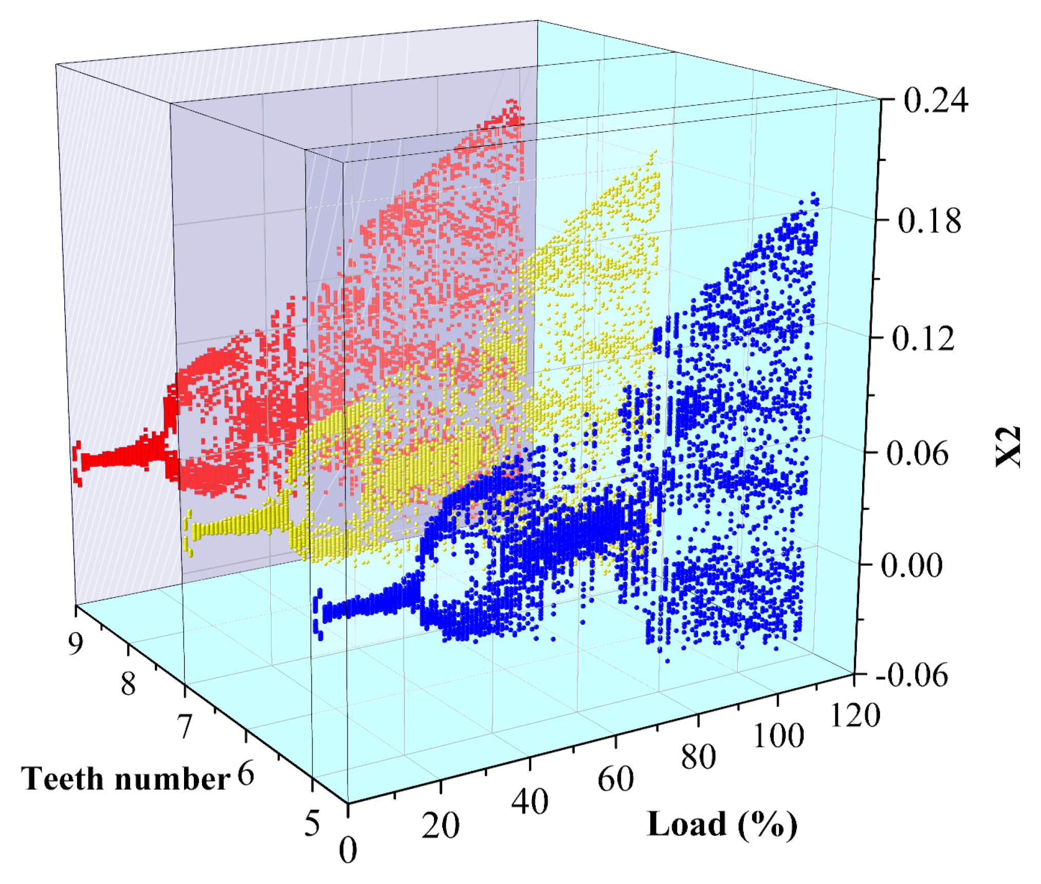
Figure 7 shows the bifurcation diagram corresponding to different numbers of seal teeth. It can be seen from the diagram that at the initial load, the corresponding systems of five teeth, seven teeth and nine teeth all experience the process of “inverted bifurcation” from a two-phase motion with a chaotic tendency toward a chaotic one-cycle motion. Blue corresponds to five teeth, yellow corresponds to seven teeth, and red corresponds to nine teeth. In the paper, THA is used to describe the load. Under the 20–40%THA condition, the motion law of the system changes obviously with the increase in load, during which the system experiences “chaotic two-period” motion, and the phenomenon of “double bifurcation” appears in the bifurcation diagram. The system response points are relatively concentrated in the bifurcation diagram under the 40–100%THA condition. With the increase in the number of teeth, the response points of the system become more dispersed. After 100%THA, the vibration area of the system increases and the amplitude increases. The response points in the bifurcation diagram spread to both ends, and there are five relatively concentrated regions. So, the change in the number of seal teeth has little effect on the system in this condition, and the motion state of the system does not change obviously.
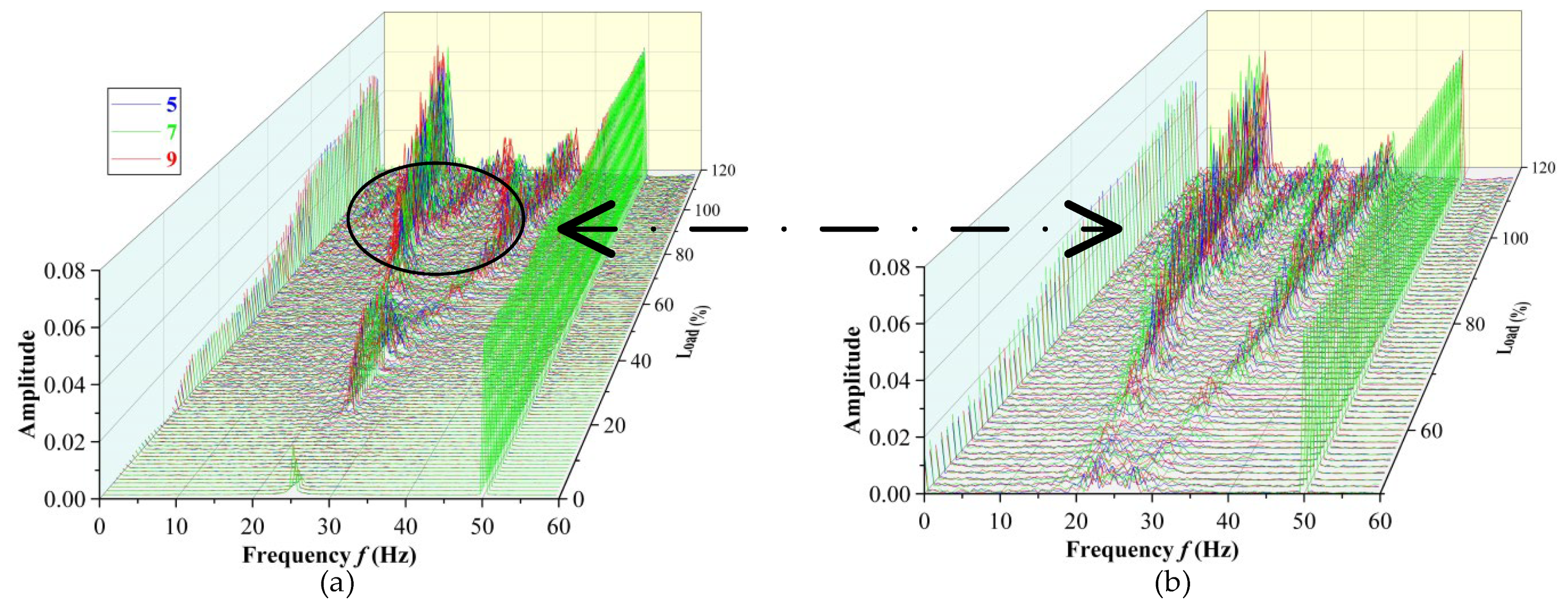
Figure 8 shows the three-dimensional waterfall diagram and a partially enlarged diagram corresponding to different numbers of teeth. Before 20%THA, five teeth, seven teeth and nine teeth appear to have a transient semi-power frequency vibration with the increase in load. Under the 20–60%THA condition, the amplitude fluctuation law of the frequency spectrum corresponding to the three kinds of tooth numbers is similar. The amplitude of a 1/2 power frequency vibration of the three tooth numbers increased steadily to about 0.02 and decreased gradually after 40% THA, and there is a tendency to differentiate between the 1/3 and 2/3 power frequency vibrations. From 60% THA to 100% THA, as shown in the partially enlarged diagram, the amplitudes corresponding to a 1/3 power frequency and a 2/3 power frequency of the three tooth numbers increase. After 100% THA, there is an obvious dense frequency phenomenon, and the three teeth numbers all form 1/3 and 2/3 power frequency vibrations. Although the change curves are highly similar, the corresponding amplitudes are different. The amplitude of a 2/3 power frequency vibration is 1/3 that of a 1/3 power frequency. At the same time, a 1/2 power frequency vibration gradually increases after 100%THA, but the amplitude is lower than a 1/3 power frequency and a 2/3 power frequency. As the load increases, the dense frequency phenomenon became more and more obvious and serious, reflecting that the higher the load, the more disordered the flow field in the seal, the greater the steam-flow-exciting force, and the more the other frequency vibrations in the multi-frequency whirl begin to show.
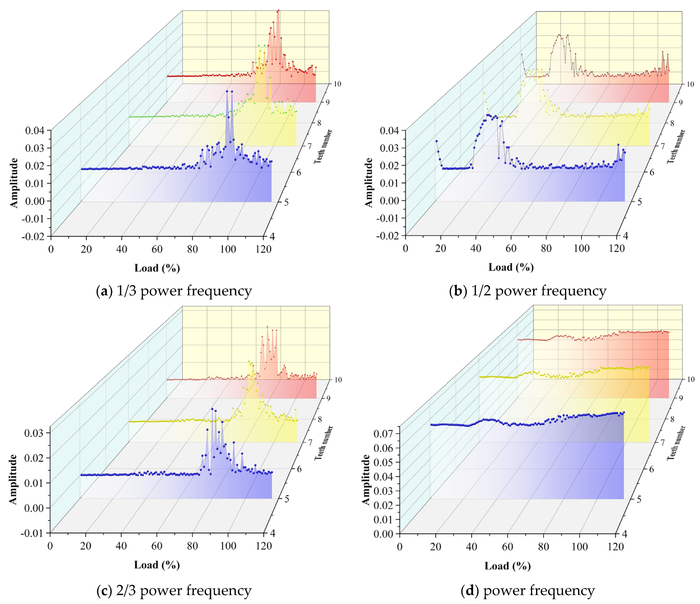
Figure 9 is a dimensionless amplitude diagram of the main frequencies of different seal tooth numbers. Blue corresponds to five teeth, yellow corresponds to seven teeth, and red corresponds to nine teeth. Before 30%THA, the amplitudes corresponding to the main frequencies of three teeth are roughly the same, indicating that the influence of the teeth number on the steam flow excitation at low load can be ignored, and the system is relatively stable. With the increase in load, the influence of steam excitation begins to appear. Beginning with the 30%THA, a 1/2 power frequency vibration begins to evolve into the 1/3 and 2/3 power frequency vibration. As the amplitude corresponding to a 1/2 power frequency gradually decreases, the amplitude corresponding to a 1/3 power frequency and a 2/3 power frequency begins to fluctuate slightly. Due to the nonlinear characteristics of steam-exciting force, the amplitude of different teeth is different.
Figure 9a–c show the change in the dimensionless amplitude of three tooth numbers at a 1/3, 1/2 and a 2/3 power frequency under different loads. The overall trends of the 1/3 power frequency and 2/3 power frequency amplitudes corresponding to three teeth are the same, which is that the fluctuation rises to the highest level and then gradually decreases, but the amplitude deviates. The amplitude corresponding to a 1/2 power frequency fluctuates steadily and tends to increase after 100%THA. This is because the influence of oil film force, unbalanced mass force, gravity and steam-flow-exciting force on the motion characteristics of the rotor is considered comprehensively. At the low load, the steam-flow-exciting force is relatively small, the oil film force and unbalanced mass force are the main forces, so the vibration caused is mainly 1/2 power frequency. With the increase in load, the influence of steam-flow-exciting force is enhanced. After 60%THA, the effect of steam-flow-exciting force is enhanced, and the 1/2 power frequency vibration gradually evolves into the 1/3 and 2/3 power frequency vibration. The steam-flow-exciting force excites the vibrations at low frequencies and critical frequencies. Under the 90–100%THA condition, the vibration direction of these two frequencies is consistent. The frequency amplitude change is the same, but the low-frequency steam-flow-exciting force is strong, so the amplitude value of a 1/3 power frequency is relatively larger.
Figure 9d is the amplitude diagram of power frequency. The amplitude change is not nonlinear, and it begins to stabilize after 100%THA.
3.2. Influence of Seal Tooth Lengths on System Motion Characteristics
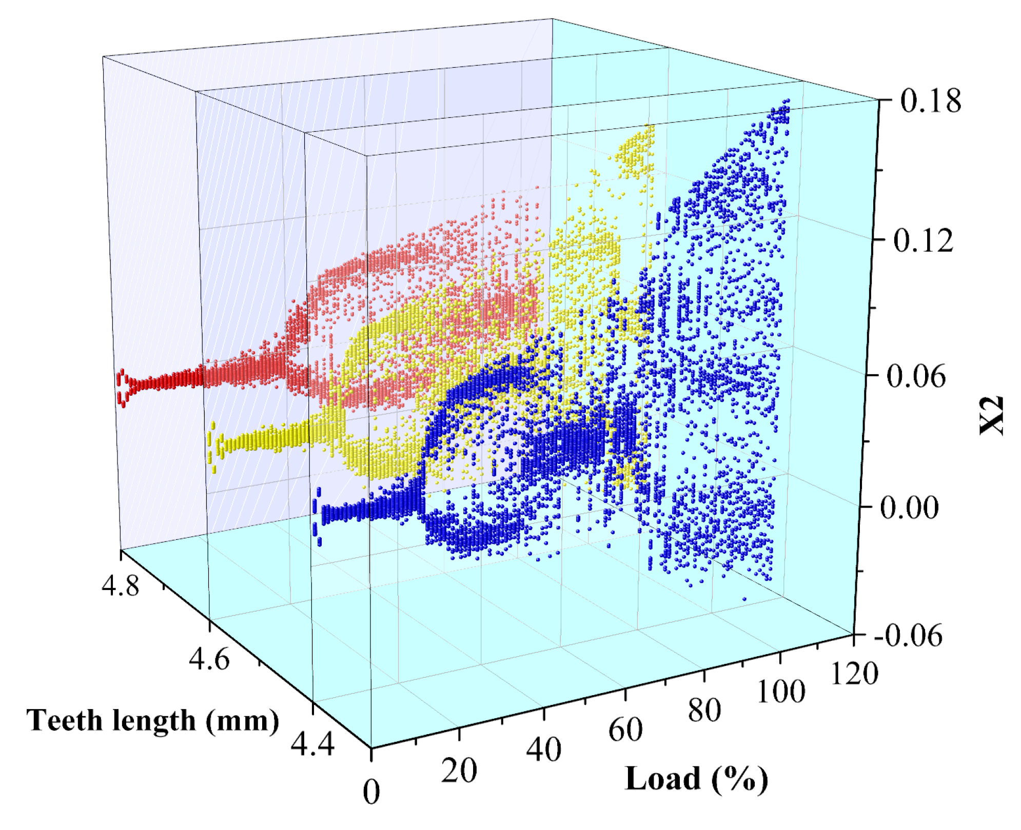
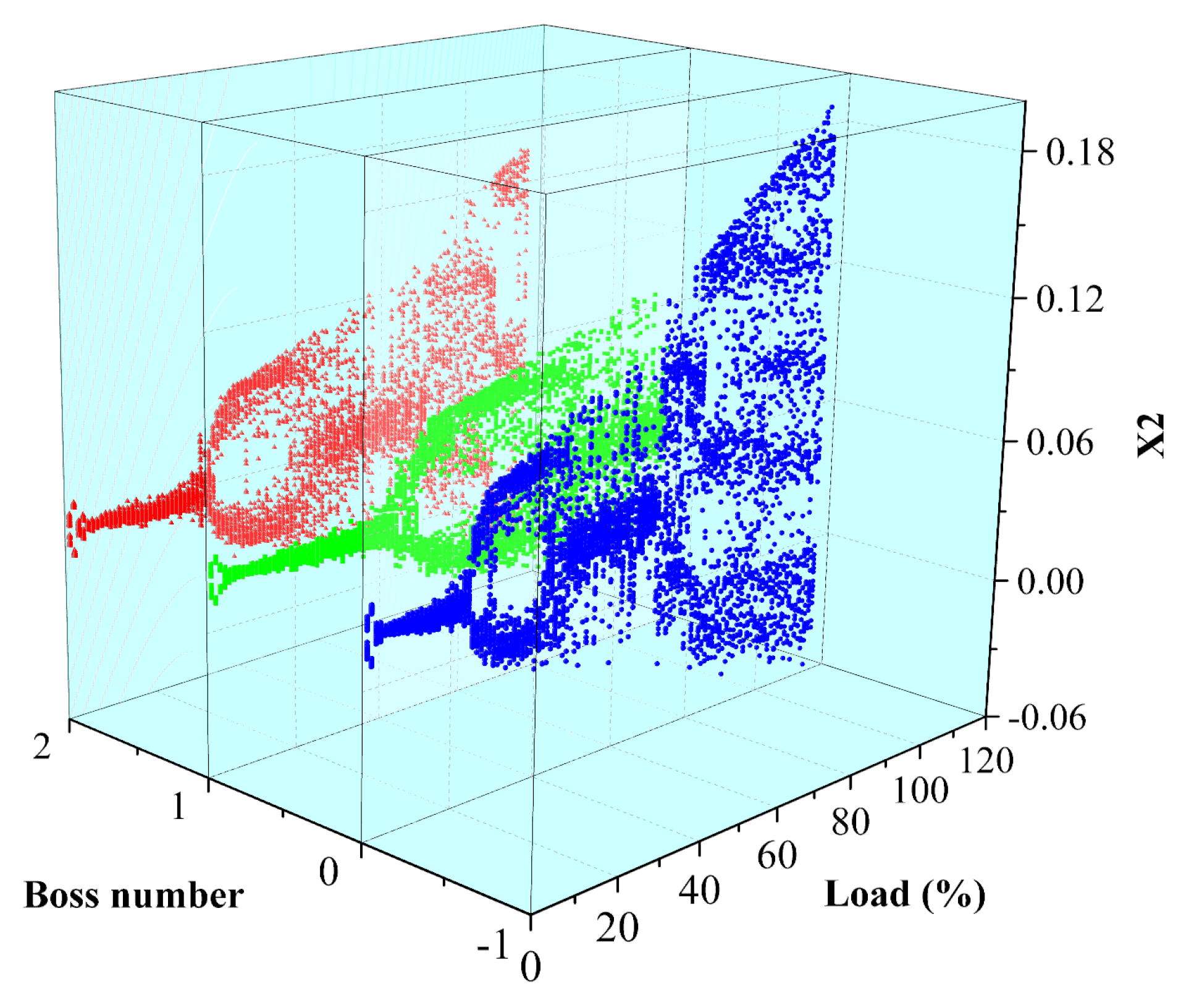
Figure 10 shows the three-dimensional bifurcation diagram of the corresponding system with different teeth lengths. Blue corresponds to 4.4 mm, yellow corresponds to 4.6 mm, and red corresponds to 4.8 mm. The systems corresponding to different teeth length also undergo the process of “inverted bifurcation” at the initial load. Under the 20-40%THA condition, the motion state of the system corresponding to the teeth length of 4.4 mm changes, and the system goes through the “chaotic two-periodic” motion. After 40%THA, the system enters chaotic motion, but the amplitude has an obvious concentrated area. When the tooth length increases to 4.6 mm, the system experiences the “chaotic two-period” motion under 30–50%THA condition, and the motion state of the system changes, and then it also enters the chaotic motion. When the tooth length increases to 4.8 mm, the “chaotic two-period” motion occurs under 40–80%THA condition. After 80%THA, the system undergoes chaotic motion. The increase in tooth length will delay the change in the motion state of the system and maintain the stability of the system. After 80%THA, the system experiences chaotic motion, but with the increase in tooth length, the amplitude distribution range of the system decreases gradually. The reason is that with the increase in tooth length, the throttling effect of sealing tooth increases, the carrying effect of rotor surface becomes stronger, the axial speed decreases, and the carrying effect of the rotor surface becomes stronger. At the same time, with the increasing load, the steam pressure and flow rate of sealing inlet increase, and the effect of long tooth is more significant.
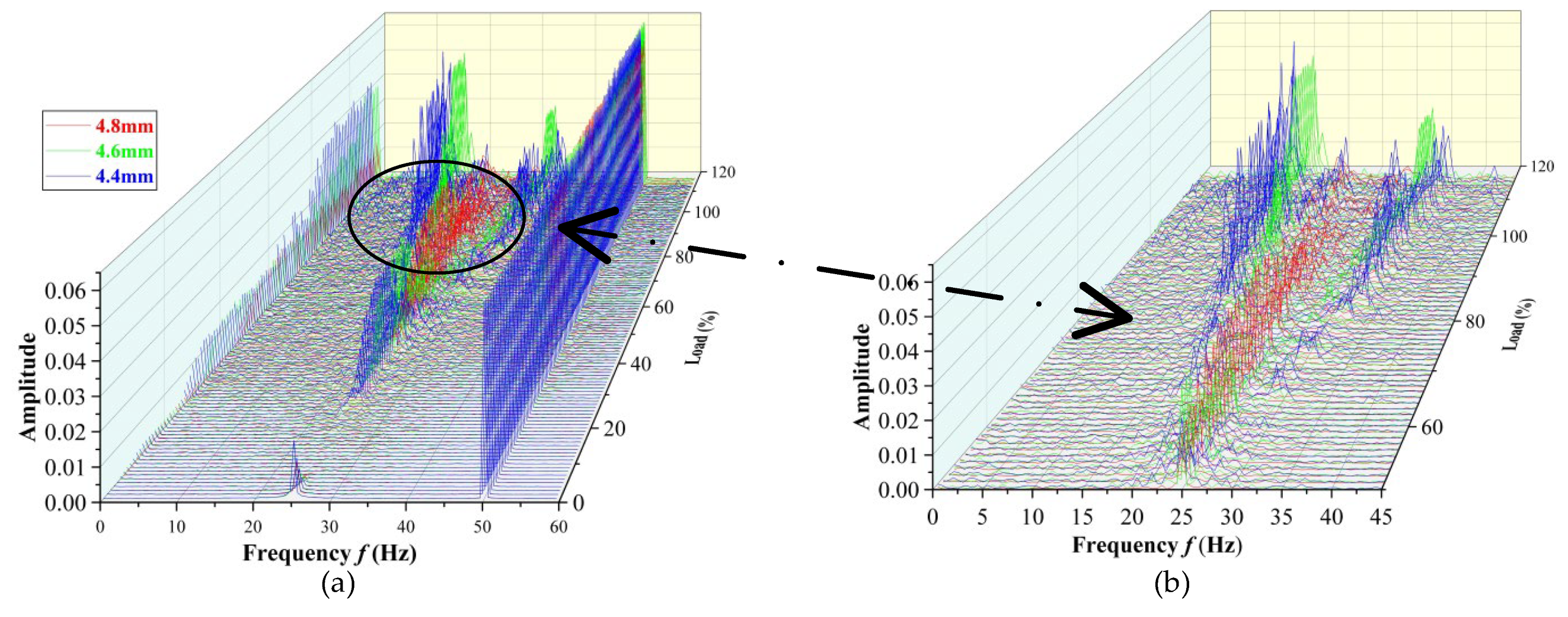
Figure 11 shows the three-dimensional spectrum corresponding to different seal teeth lengths. As shown in the figure, the system experienced a short half-frequency vibration during the initial load. At the beginning of 20%THA, a 1/2 power frequency begins to appear in the spectrum corresponding to the system with a tooth length of 4.4 mm, and with the increasing load, the corresponding amplitude increases slowly. At about 40%THA, the amplitude corresponding to a 1/2 power frequency decreased and differentiated to both ends, resulting in the 1/3 and 2/3 power frequencies. As the teeth length increases, the load corresponding to the 1/2 power frequency of the system increases. When the tooth length increases to 4.8 mm, the 1/2 power frequency appears at 40%THA and gradually decreases at 80%THA, but there are no obvious 1/3 and 2/3 power frequencies. After 80%THA, there is a load range where the dense frequency phenomena are concentrated. In this range, as the tooth length increases, the dense frequency phenomenon decreases. This is because as the tooth length increases, the tip clearance becomes smaller, the throttling effect is enhanced, the sealing leakage resistance becomes better, the steam pressure in the sealing chamber decreases, and the steam-flow-exciting force becomes smaller; therefore, the frequency division vibration in the multi-frequency whirl is weakened.
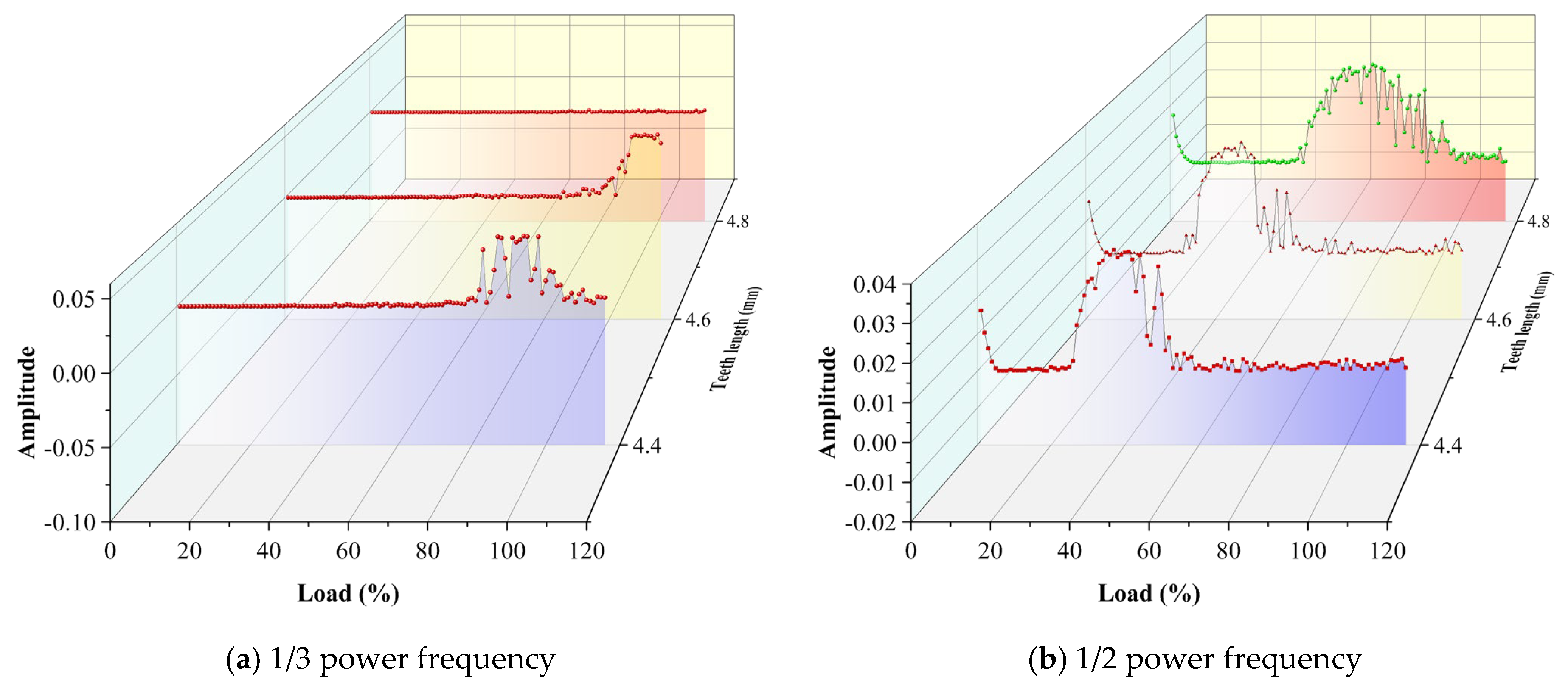
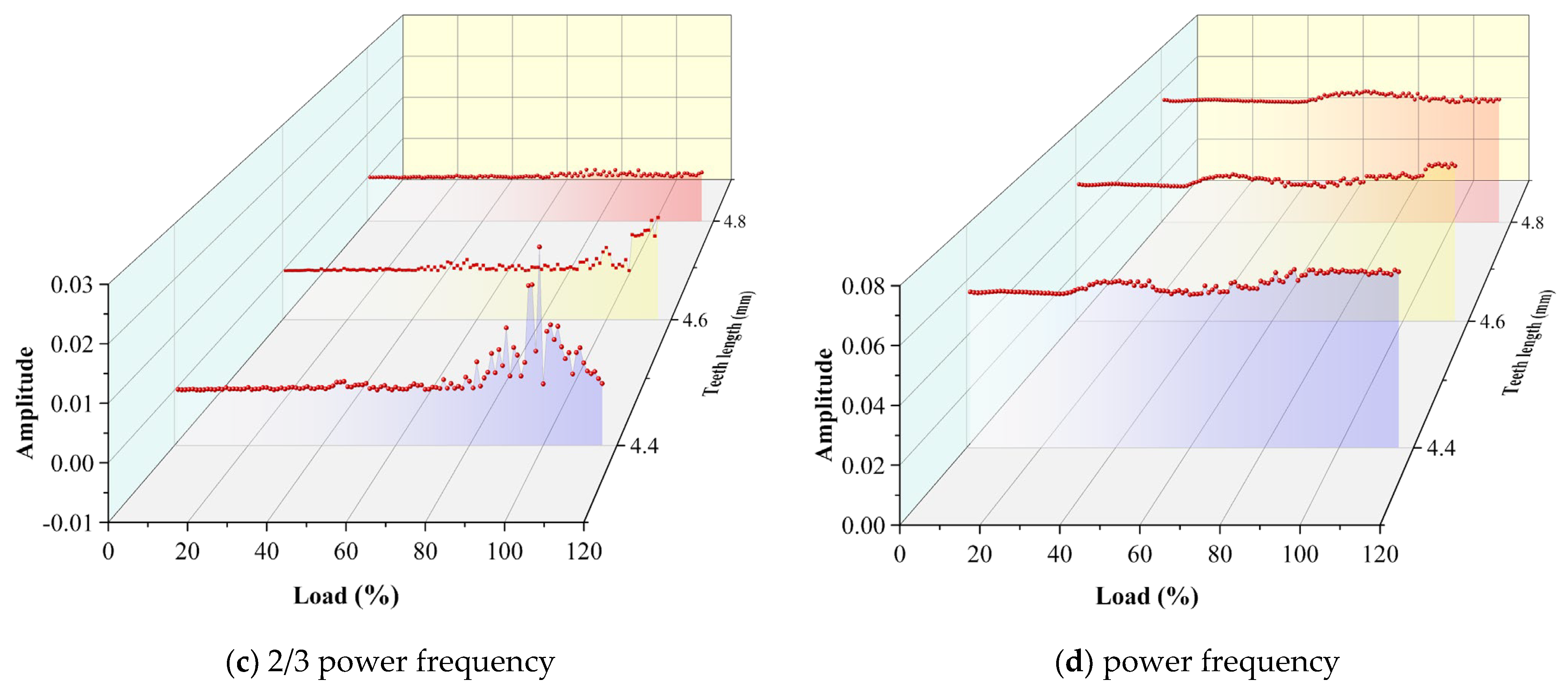
Figure 12 shows the amplitude diagram of the main frequency of the system corresponding to different seal tooth lengths. Blue corresponds to 4.4 mm, yellow corresponds to 4.6 mm, and red corresponds to 4.8 mm. The system corresponding to the tooth length of 4.4 mm, a 1/3 power frequency, a 1/2 power frequency and a 2/3 power frequency appear earliest in the same load range, and the corresponding amplitude is the largest. The system corresponding to the tooth length of 4.8 mm does not show the obvious 1/3 power frequency and 2/3 power frequency corresponding to the smaller amplitude. However, after 100%THA, the 4.4 mm tooth length has a sharp decrease in the amplitude of the local load at a 1/3 power frequency, which reflects the strong nonlinearity of the steam-exciting force. The 4.8 mm tooth length has a good suppression effect on the steam excitation after 100%THA. Under the general law, there will still be a phenomenon that the amplitude of the short tooth length decreases sharply and rebounds.
3.3. Influence of Boss Numbers on Motion Characteristics of System
Figure 13 shows the bifurcation diagram of the system corresponding to the different numbers of the bosses. Blue corresponds to the number of boss 0, yellow corresponds to the number of boss 1, and red corresponds to the number of boss 2. The phenomena of “inverted bifurcation” also appear in the bifurcation diagram of the system corresponding to different numbers of bosses at the initial load, because the steam flow excitation has little influence on the system. So, the motion law of the system is roughly similar. Under the 20–80%THA condition, the system with the number of boss 0 first changes from chaotic motion to “chaotic two-period” motion. But the systems with the numbers of boss 1 and 2 are more stable, and the motion state changes later. Under the 80–100%THA condition, with the increase in the number of bosses, the response points of the system gradually converge, especially when the numbers of bosses are 0 and 1, the aggregation phenomena are the most obvious, the chaos of rotor motion is weakened, and the number of the boss plays a role in restraining chaos. But when the number of the boss increases to 2, the response points in the system bifurcation diagram are more discrete relative to the number of the boss, and the degree of discretization is less than that for the boss 0. Three obvious concentrated regions gradually form after 100%THA, which means that the system goes through a “chaotic three-period” motion. The chaotic trend of the boss 0 platform is more obvious, and the covering load is greater because there is no bump blocking, the steam leakage is large, the axial flow is smooth and fast, and the pressure is large but the fluctuation of the pressure is small, and the stable steam-flow-exciting force is aroused, forming obvious chaotic motion.
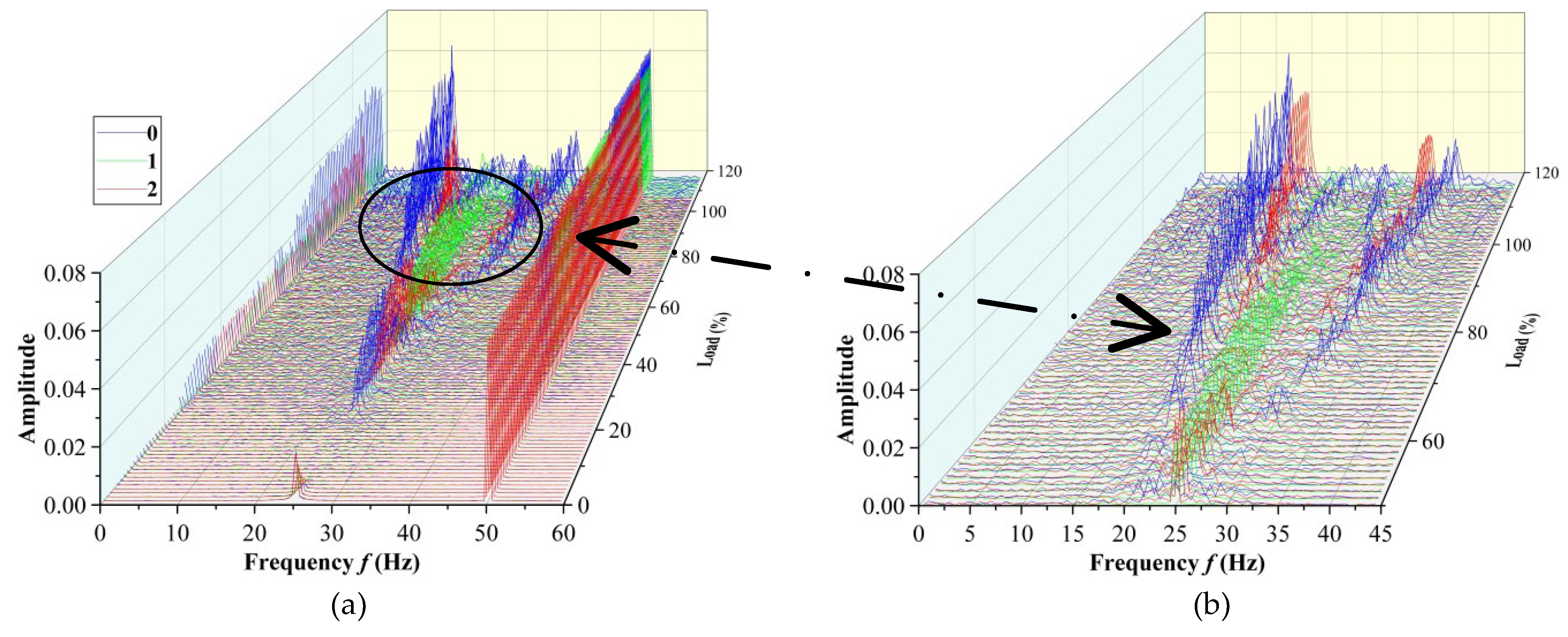
Figure 14 is the three-dimensional spectrum diagram and partially enlarged diagram of the system corresponding to different bosses. As shown in the diagram, the system with boss 0 first appears as a 1/2 power frequency component under the 20–80%THA condition. At the beginning of 30%THA, a 1/2 power frequency component gradually begins to decrease and the 1/3 and 2/3 power frequencies appear, but the amplitude change is small. After 80%THA, it can be seen from
Figure 14b that the amplitude corresponding to the 1/3 and 2/3 power frequencies corresponding to boss 0 increases significantly. When the number of bosses increases to 1, the 80%THA in the spectrum of the corresponding system is dominated by the power frequency component of 1/2, and the corresponding amplitude is large. As the load continues to increase, the amplitude corresponding to a 1/2 power frequency gradually decreases, and other power frequency components with lower amplitude are derived. However, as the number of bosses increases to 2, at about 60%THA, the amplitude corresponding to a 1/2 power frequency of the system almost disappears, and the 1/3 power frequency and 2/3 power frequency components begin to appear, but the corresponding amplitude is low. With the increase in load, it remains relatively stable. However, the amplitude corresponding to the 1/3 and 2/3 power frequencies increases significantly at 100%THA. After 80%THA, the dense frequency phenomena appear in the spectrum diagram, and the dense frequency phenomena are the most serious in the spectrum diagram of the system corresponding to boss 0.
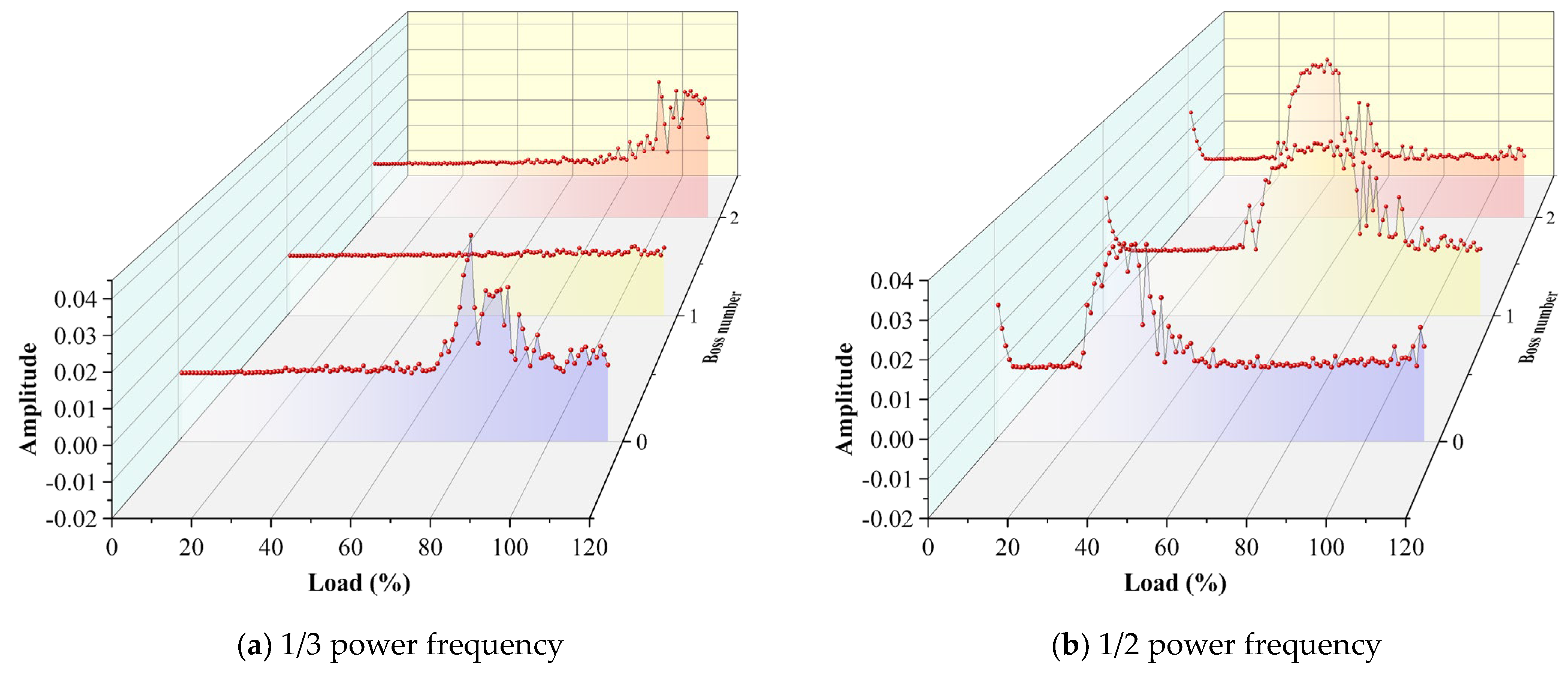
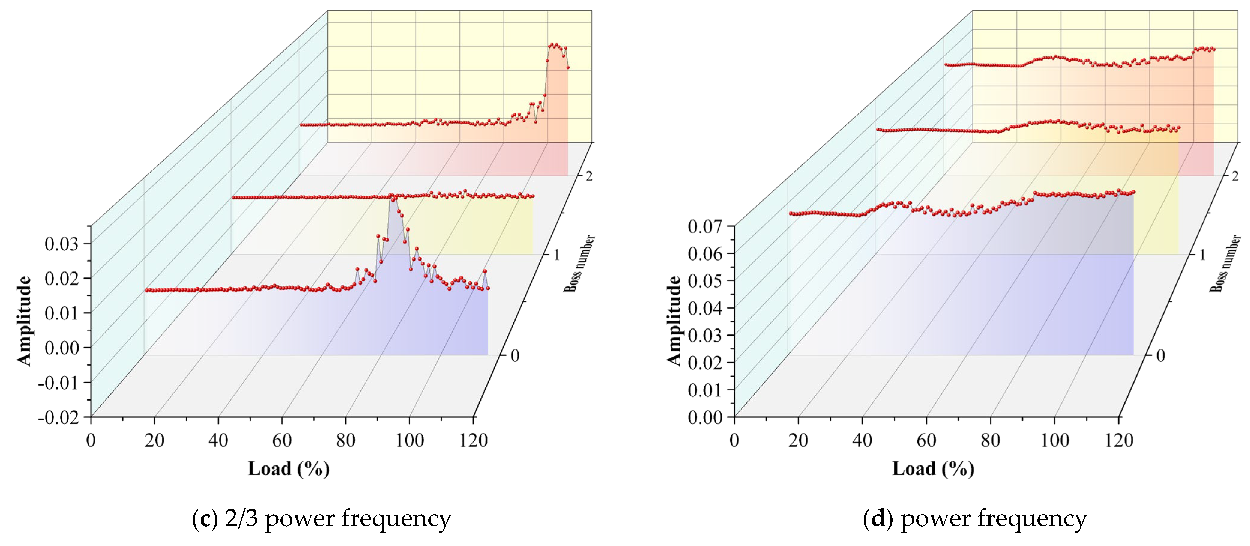
Figure 15 is the amplitude diagram of the main frequencies corresponding to the different numbers of the bosses. Blue corresponds to the number of boss 0, yellow corresponds to the number of boss 1, and red corresponds to the number of boss 2. From
Figure 15b, it can be seen that the system corresponding to the boss 0 first appears at the 1/2 power frequency and then approximately disappears after 60%THA. Combined with
Figure 15a,cc, after 60%THA, the 1/3 and 2/3 power frequencies begin to appear and gradually decrease after the largest amplitude of 70%THA. When the number of the boss increases to 1, the corresponding power frequency of 1/2 appears the latest, and the amplitude of the corresponding power frequencies of 1/3 and 2/3 is the smallest. Although there is little difference between the load of the 1/2 power frequency vibration corresponding to the number of boss 2 and the number of boss 1, the amplitudes of the power frequencies corresponding to 1/3 and 2/3 increase sharply after 100%THA. This is due to the fact that with the increase in the number of bosses, the throttling effect in the sealing cavity increases and the leakage decreases, so that the influence of steam-flow-induced vibration weakens. At this time, the influence of the system should be mainly a nonlinear oil film force and the unbalanced response of the rotor. This leads to a relatively strong 1/2 power frequency vibration. However, the increase in the number of bosses will cause the instability of the flow field and the nonlinearity of steam-induced vibration, which will also have a certain impact on the stability of the system with the increase in load.
3.4. Stability Analysis of Rotor System under Different Sealing Structures
The largest Lyapunov exponent is an important quantitative index to evaluate the stability of a rotor dynamic system, which represents the average exponential rate of convergence or divergence between adjacent orbits in phase space. If the exponent is positive, it shows that the system is chaotic and the stability is poor. If it is negative, it shows that the system is in periodic deterministic motion and has good stability. Chaos refers to the uncertain or unpredictable random phenomenon of a certain macroscopic nonlinear system under certain conditions, and it is also a phenomenon of the integration of certainty and uncertainty, regularity and irregularity or orderliness and disorder.
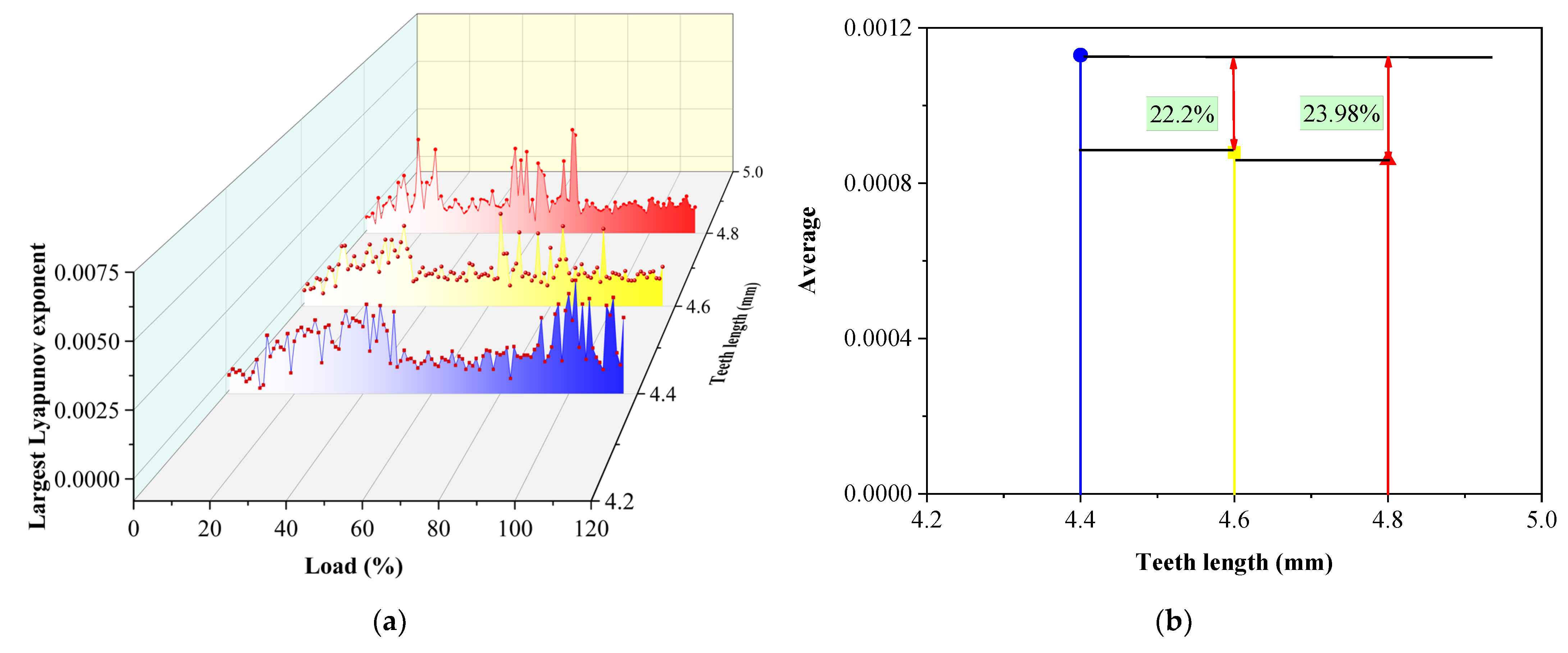
Figure 16a shows the largest Lyapunov exponent corresponding to different teeth lengths. Blue corresponds to 4.4 mm, yellow corresponds to 4.6 mm, and red corresponds to 4.8 mm in
Figure 16a,b. When the tooth length is 4.4 mm, at the initial load, the largest Lyapunov exponent increases from “touching zero point”, and the exponent value fluctuates greatly and tends to be flat at 50%THA. When the load increases to 90%THA, due to the influence of steam flow excitation, vibration is enhanced; the chaos of the system is enhanced too, and the fluctuation of exponential value is more intense. When the tooth length increases to 4.6 mm, although the chaotic characteristic of the same system is strong at the initial load, after 40%THA, the system begins to stabilize and the exponential value fluctuates gently. Beginning with 60%THA, the exponential value fluctuates strongly because of the nonlinear enhancement of steam-flow-induced vibration. With the continuous increase in load, the effect of teeth length on steam-induced vibration appears initially, the exponential value returns to stable, and the system is relatively stable too. When the tooth length is 4.8 mm, the exponent value fluctuates smoothly in advance, and in the high load area, the inhibitory effect of teeth length on steam-flow-induced vibration is enhanced and the system remains stable. Combined with the analysis of
Figure 16b, when the tooth length increases to 4.6, the average exponent value decreases by 22.2%. When the tooth length increases to 4.8 mm, the average exponent value decreases by 23.98%. The law reflected is more practical in this paper because CFD is used to simulate the three-dimensional multi-frequency whirl of the rotor.
With the increase in teeth length, the carrying capacity of the rotor is enhanced, the circumferential velocity of the steam increases, the axial speed decreases, the anti-leakage effect increases, and the stability of the rotor becomes better.
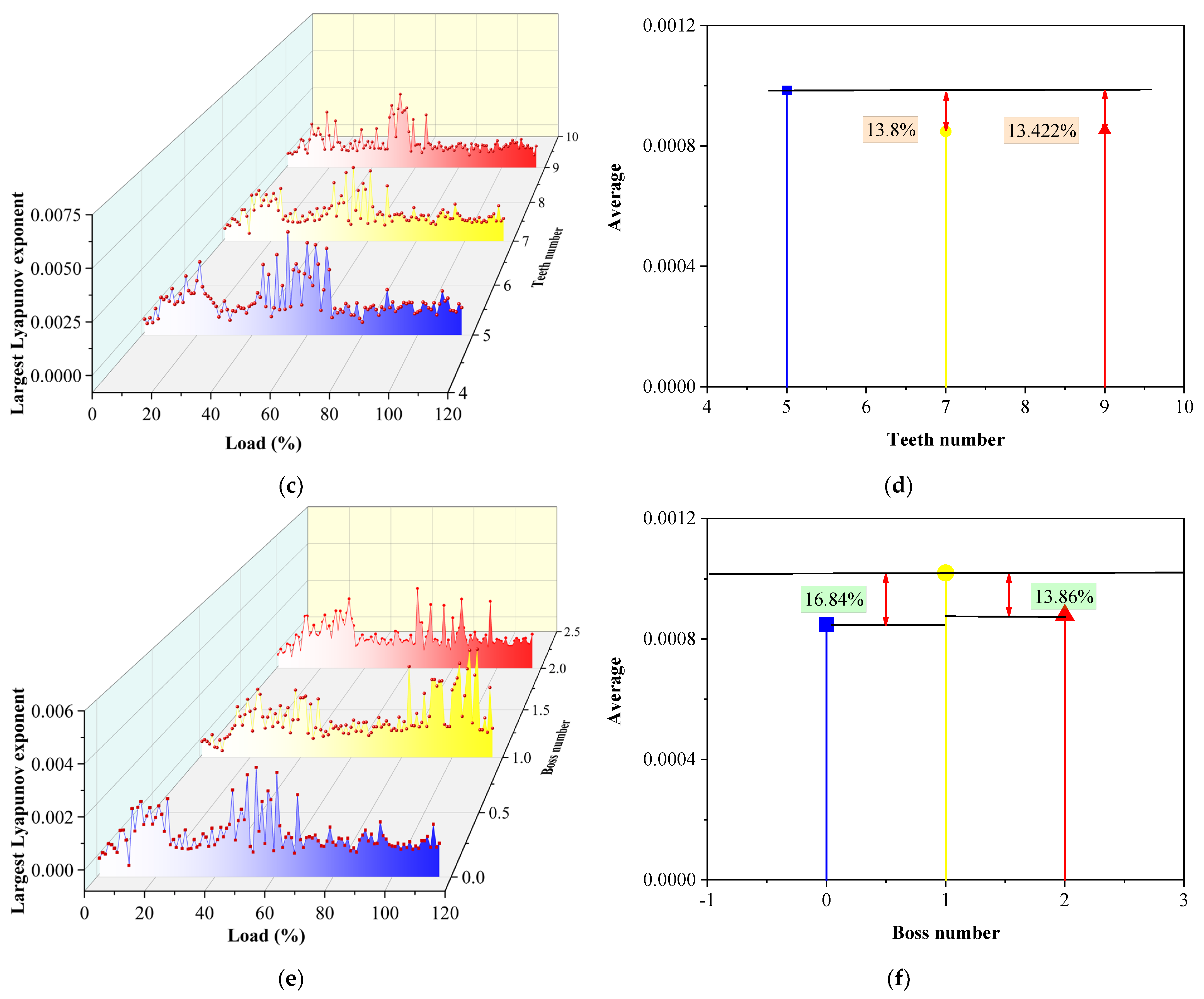
Figure 16c shows the largest Lyapunov exponent chart corresponding to different numbers of teeth. Blue corresponds to five teeth, yellow corresponds to seven teeth, and red corresponds to nine teeth in
Figure 16c,d. The change in the number of teeth has little effect on the stability of the system, and the law of the largest Lyapunov exponent is basically unchanged. Combined with
Figure 16d, when the number of teeth increases to seven teeth and nine teeth, the average exponent value decreases by 13.8% and 13.422%, respectively. This is because the change in the number of teeth does not affect the tooth tip clearance, and the ability of the rotor to carry steam in the circumferential direction remains unchanged, which has little effect on the axial speed, so it has little influence on the stability of the system.
Figure 16e shows the largest Lyapunov exponent corresponding to the different numbers of the bosses. Blue corresponds to the number of boss 0, yellow corresponds to the number of boss 1, and red corresponds to the number of boss 2 in
Figure 16e,f. When the number of the boss is 0, the exponent has a strong jump before 80%THA, indicating that the chaos of the system is strong during this period, especially during the period from 40%THA to 70%THA. Then, with the increase in load, the exponent value fluctuates smoothly and the system is stable. When the number of the boss is 1, the stability of the system is poor and the exponential value fluctuates greatly under a low load. Under 40–90%THA condition, the exponent value fluctuates gently and the chaos of the system is weakened. However, after 90%THA, the exponential value fluctuates sharply, indicating that the stability of the system is weak. When the number of the boss increases to 2, the exponent value fluctuates greatly before 30%THA, and with the continuous increase in load, although a few exponent values jump under 60–90%THA condition, the overall value is relatively flat. Combined with
Figure 16f, when the number of the boss increases to 1, the average exponent increases by 16.84%, and when the number of the boss increases to 2, the average exponent decreases by 13.86% relative to that of the boss number 1. The reason is when there is no boss, the lengths of the sealing tooth are the same, so it becomes a flat-toothed seal, the flow field is stable, there is no complex vortex system, and the steam flow excitation vibration is stable. But boss 0 can lead to steam leakage increasing, which reduces power.
In summary, the change in the number of seal teeth has a relatively small impact on the system state, and the motion state of the system does not change obviously. As the system load increases, the internal flow field of the seal becomes more chaotic, and the steam-flow-exciting force also increases accordingly. The increase in seal tooth lengths and the decrease in blade tip clearance enhance the throttling effect, reduce the steam pressure inside the chamber, and decrease the steam-flow-exciting force. As the load increases, the pressure and flow rate at the sealing inlet increase, and the impact on the long teeth becomes more significant. The system with a tooth length of 4.8 mm has a good suppression effect on steam excitation after 100% THA. The number of the boss increases, the leakage decreases, the steam excitation effect weakens, and the chaotic state of rotor motion weakens. When boss 0 is used, the internal coverage load of the seal is high, and the steam leakage is large. However, it makes the axial flow inside the seal smooth, the pressure fluctuation small, and the steam excitation stable. When the number of the boss increases to 2, the degree of discretization is less than that of boss 0, indicating that the boss plays a role in uniform chaos.
