Article

The Effect of Support Misalignment on Vibration Characteristics of Aero-Engine Rotor Systems under Ultra-High Operating Speeds

1
School of Mechanical and Electrical Engineering, Central South University, Changsha 410114, China
2
Hunan Aviation Powerplant Research Institute, AECC, Zhuzhou 412002, China
*
Author to whom correspondence should be addressed.
Machines 2024, 12(10), 669; https://doi.org/10.3390/machines12100669
Submission received: 30 August 2024 / Revised: 21 September 2024 / Accepted: 23 September 2024 / Published: 24 September 2024
(This article belongs to the Section Turbomachinery)

Abstract

:
In order to ensure the vibration safety of rotor systems in the next generation of aero-engines and reduce the impact of misalignment faults, the effect of support misalignment on the vibration characteristics of rotor systems under ultra-high operating speeds is investigated in this paper. Firstly, an analytical excitation model of the rotor systems under ultra-high operating speeds is established, considering the impact of the support misalignment. Then, based on the model of the misaligned combined support system, the dynamic model of the flexible discontinuous rotor support system with the support misalignment is presented. Subsequently, based on the established model, the effects of support parameters and support misalignment amounts on the vibration characteristics of the rotor support system are analyzed. Finally, experimental validation of the research findings is conducted. The research result shows that the support misalignment increases the vibration response of the rotor, reduces the vibration reduction efficiency of the combined support system, and consequently decreases the vibration safety of the rotor support system.

1. Introduction

Due to machining and assembly errors as well as the wear in rotor systems after a period of operation, misalignment faults are bound to occur [1]. Misalignment faults can lead to increased vibration responses of the rotor system and may also trigger other issues, such as the wear of the bearing and the instability of the squeeze film damper. In rotor systems, 70% of vibration failures are due to misalignment faults [2].
Clearly, the vibration safety of misaligned rotor systems is crucial for ensuring the vibration safety of the rotor, and the vibration characteristics of misaligned rotor systems provides an important theoretical basis for the design and fault diagnosis of actual rotors.
Considering that misalignment primarily occurs at the couplings and bearings, researchers first analyzed the excitation characteristics of misalignment in different bearings and couplings and studied the effects of misalignment of different bearings and couplings on the vibration characteristics of the rotor.
For instance, Gibbons [3] derived analytical equations for excitations of various coupling misalignments. Liufang Shentu et al. [4] investigated the nonlinear vibration response of rotors under angular misalignment of a laminated coupling, determining how the rotor system varies with changes in rotational speed and angular misalignment. Hongliang Li [5] studied the nonlinear vibration characteristics of misaligned rotor system with a ball bearing. Bouaziz S et al. [6] established a dynamic model of a dual-rotor system, considering angular misalignment in fluid-dynamic sliding bearings, revealing the dynamic characteristics of the bearings under angular misalignment conditions. In addition, scholars have also studied the effects of factors such as misalignment parameters [7] and operating conditions [8] on the vibration characteristics of misaligned rotors.
To meet the engineering application requirements of modern rotating machinery, scholars have further investigated the impact of the structural characteristics of actual rotor systems, the distribution of supports, and the coupling effects of excitations on the vibration characteristics of misaligned rotors. Al-Hussain K M et al. [9] established a dynamic model for a two-span rotor system considering angular misalignment. Zhenbo Zhang et al. [10] analyzed the impact of misalignment on the rotor dynamics characteristics of multi-span rotors. Guang Zhao et al. [11] studied the hyperstatic structural characteristics of low-pressure rotors in aircraft engines and analyzed the vibration characteristics under both perfectly aligned and tail support misalignment conditions. Leike Zhang et al. [12] researched the vibration characteristics of rotor systems under the coupling effects of rubbing forces and coupler misalignment. Pengfei Wang et al. [13] focused on the planetary gear transmission system of tracked vehicles, investigating the dynamic characteristics of the planetary gear set-misaligned rotor system.
In summary, scholars have conducted extensive and in-depth research on the dynamic characteristics of misaligned rotors. However, the existing research results are not fully applicable to the rotor systems of aero-engines, operating at ultra-high speeds, for the following reasons:
The aero-engine rotor is a discontinuous rotor, and its stiffness is lower than that of conventional rotors. Additionally, the operating speeds of the new generation of advanced aero-engine rotor support systems are significantly higher than those of the existing rotor systems. The above two factors mean that bending deformations in the new generation of advanced aero-engine rotor support systems is quite significant. However, the effect of bending deformation under ultra-high operating speeds and the discontinuity of modern aero-engine rotors are ignored while establishing dynamic models of rotors with support misalignments in existing studies.
The shortcoming of modeling results in discrepancies between the dynamic model and the actual rotors under ultra-high operating speeds, making it difficult to meet the research needs for the vibration characteristics of the new generation of aero-engine rotor systems.
Therefore, it is necessary to research the dynamic characteristics of rotor systems with a support misalignment under ultra-high operating speeds, considering the non-continuity of the rotors and the effects of the bending deformation of rotors, for the safety of the new generation of aero-engine rotor systems.
This article takes a typical aircraft engine discontinuous rotor system as the research object to investigate the impact of a support misalignment on the vibration safety of rotor systems under ultra-high speeds. Firstly, an analytical excitation model of the misalignment is established, considering the effects of the bending deformation of flexible rotors caused by the support misalignment on excitations and support systems. Then, based the presented analytical excitation model, the dynamic model of the flexible discontinuous rotor system with curvic couplings is provided. Furthermore, the vibrational characteristics of the aero-engine rotor system with the support misalignment points are studied, and the vibration safety of the aero-engine rotor system with support misalignments is researched.

2. Dynamic Model of Discontinuous Flexible Rotor Support Systems with Support Misalignment

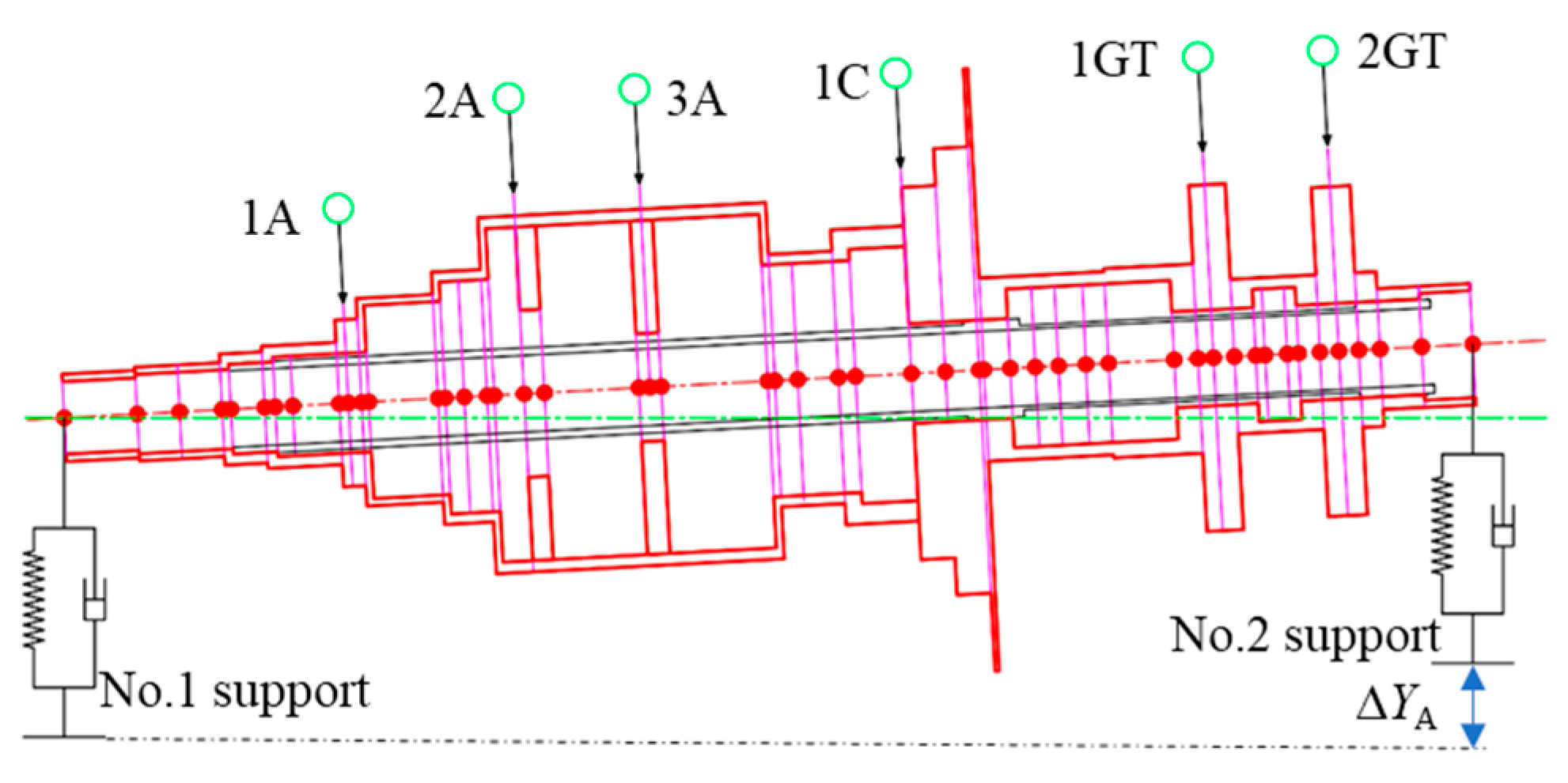
The rotor support system of the aero-engine studied in this paper is shown in Figure 1. The rotor structure of this aero rotor system consists of six discs, which include a three-stage axial flow compressor (1A, 2A, and 3A), a one-stage centrifugal compressor (1C), and a two-stage gas turbine (1GT and 2GT). The support system is a combined support system made up of two squirrel cage elastic supports (SCESs) and two squeeze film dampers (SFDs), and the distribution of supports is 1-0-1. The discs are assembled into a complete rotor through central tie rods and six curvic couplings (C1, C2, C3, C4, C5, and C6). The parameters of the rotor systems with curvic couplings can be found in reference [14].

2.1. The Equivalent Model of the Curvic Couplings

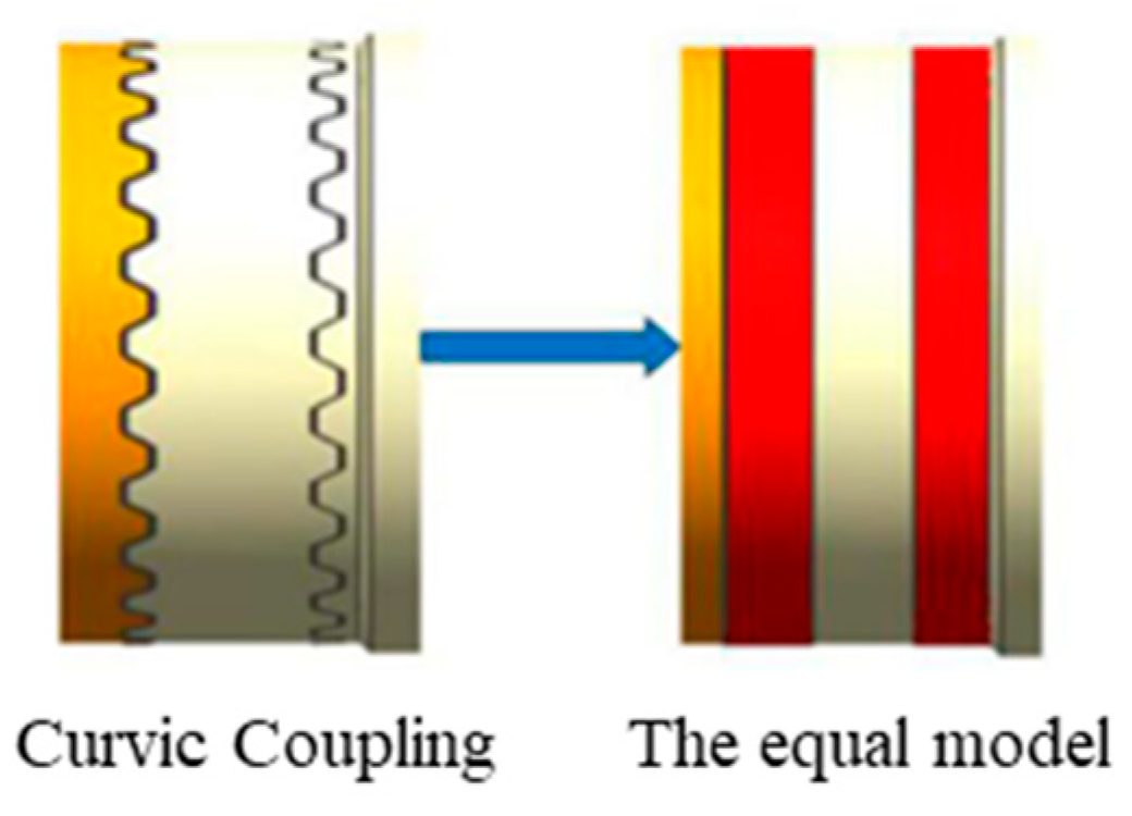
Based on the parameters of the curvic coupling, the equivalent model of the curvic couplings is established using the equivalent method in reference [14], which equivalently replaces the original curvic coupling by using an equivalent annular structure that has an equivalent elastic modulus and equivalent density, as shown in Figure 2. Since the equivalent method for the curvic coupling is not the focus of this paper, please refer to reference [14] for specific modeling and solution methods. The parameters of the six equivalent models of the original curvic coupling are presented in Table 1.

2.2. The Excitation Model with the Support Misalignment under Ultra-High Operating Speeds

When the types of supports are different, the impact of the different support misalignment varies; when the type of the supports are the same, the misalignment of supports can be equivalently represented as the misalignment between one support and another in the static condition. The type of the combined supports in the rotor system studied in this paper is the same. The supports of the research subjects in this article are identical, and the influence patterns associated with the misalignment of the two supports are consistent. Since the center of mass of the rotor system studied in this paper is close to the No.2 support, the excitation caused by misalignment is greater when the No.2 support is misaligned. Therefore, this paper assumes that the misalignment occurs at the No.2 support, while there are no misalignment and deformation at No.1 support.
As shown in Figure 3a, the amount of total misalignment ∆YA at the No.2 support of the flexible rotor is composed of the deflection νbA due to the bending deformation of the rotor and the misalignment of the elastic support in the No.2 support with the misalignment deformation ∆b of the bearing in the No.2 support. The angle α represents the angle between the rotor’s axis and the driving torque at the center of mass. The misalignment at the No.2 support will generate the force FY; therefore, the additional FY1 (FY1 = FY) and the additional bending moment MY act on the No.1 support due to the equilibrium of forces and moments. Based on deformation coordination and force balance, the relationship expressions can be established as follows:
Δ Y A = ν b + Δ b Δ b = F Y / K B M Y = L A B F Y
where, LAB is the distance from the No.1 support to the No.2 support.
The variable cross-section rotor system shown in Figure 1 is employed by the rapid analytical method [15]. There are 47 elements between the two supports of the rotor, as shown in Figure 3, and the differential equation of the deflection curve for each segment is approximately as follows:
d 4 ν 1 d z 4 = 0 , 0 z z 1 d 4 ν 47 d z 4 = 0 , z 47 z z 47
Integrate Equation (2) four times, and the general solution equations for the shear force, bending moment, angle of rotation, and deflection of each variable cross-section shaft segment are obtained. The general solution equations of the deflection curve for each segment, which contain 188 integration constants Ci (where i = 1, 2, …, 188), are derived:
ν j = C 4 j 3 z e 3 + C 4 j 2 z e 2 + C 4 j 1 z e + C 4 j  
where ze is a dimensionless z-axis coordinate, ze = z/lz; lz is the length of the rotor in the z direction; j is the number of the elements; and C4j are the coefficients of element j, obtained using Equation (2).
By substituting νbA obtained by Equation (3) into Equation (1) and rearranging, the additional excitation FY on the support can be expressed as follows [11]:
F Y = ( Δ Y ν b A ) K B cos ( 2 w t )
where w is the rotational speed.
As shown in Figure 3b, due to the support misalignment and the bending deformation of the rotor, there is an angle α between the axis of element j − 1 and the axis of element, resulting in Tj−1 being decomposed into Tsj and Tzj. The driving torque of element j is:
T s j = I R j 1 ε j 1 sin α j 1 T z j = I R j 1 ε j 1 c o s α j 1
where aj−1 represents the angle between the axis of element j − 1 and the axis of element j, a0 = 0; IRj−1 is the polar moment of inertia of element j − 1; and εj−1 is the angular acceleration of element j − 1.
The relationship between wj and wj+ can be expressed as follows [11]:
ω j ω j 1 = C j 1 1 + D j 1 c o s 2 θ j 1
where θj−1 is the angular displacement of element j − 1 and can be written as θj−1 = wj−1t; Cj−1 = 4cosaj/(3 + cos2aj); and Dj−1 = (1 − cos2aj)/(3 + cos2aj).
The derivative of the generalized binomial expansion of Formula (6) yields the following formula:
ε j ω j 1 2 = n = 1 2 n A n cos 2 n θ j 1
where An are the coefficients of the generalized binomial expansion of Equation (6).
Since the high-frequency amplitude must be much smaller than the low-frequency amplitude, the dynamic excitation caused by the driving torque of the misaligned flexible rotor is obtained by substituting Equation (7) into Equation (5) and retaining the first four terms as follows:
P T j = sin α j 1 I R j 1 ω j 1 2 n = 1 4 2 n A n cos 2 n θ j 1
where PTj represents the dynamic excitation on the element j + 1.

2.3. The Model of Misaligned Combined Support System with SFD and SCES

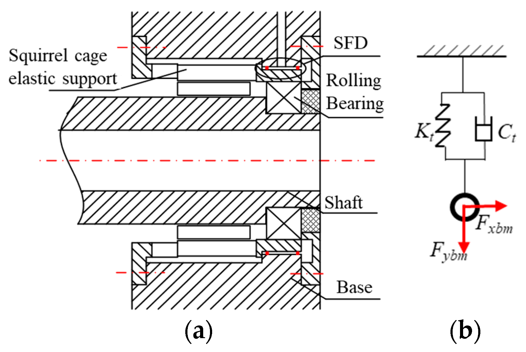
As shown in Figure 4, the combined support system is composed of a rolling bearing, a squirrel cage elastic support (SCES), and a squeeze oil film damper (SFD) connected in series.
The damping of rolling bearings can generally be neglected, and the stiffness of the rolling bearings can be found in the aircraft engine design manual [16]. The actual rolling bearings used in aircraft engine rotor systems have very small clearances; their nonlinear characteristics will not be considered in this paper.
The equivalent stiffness of the rolling bearings and SCES can be viewed as two springs connected in series, and the equivalent stiffness can be calculated using the following formula:
K t = K R + K S
where KR represents the stiffness of the rolling bearing; and KS denotes the stiffness of the squirrel cage elastic support.
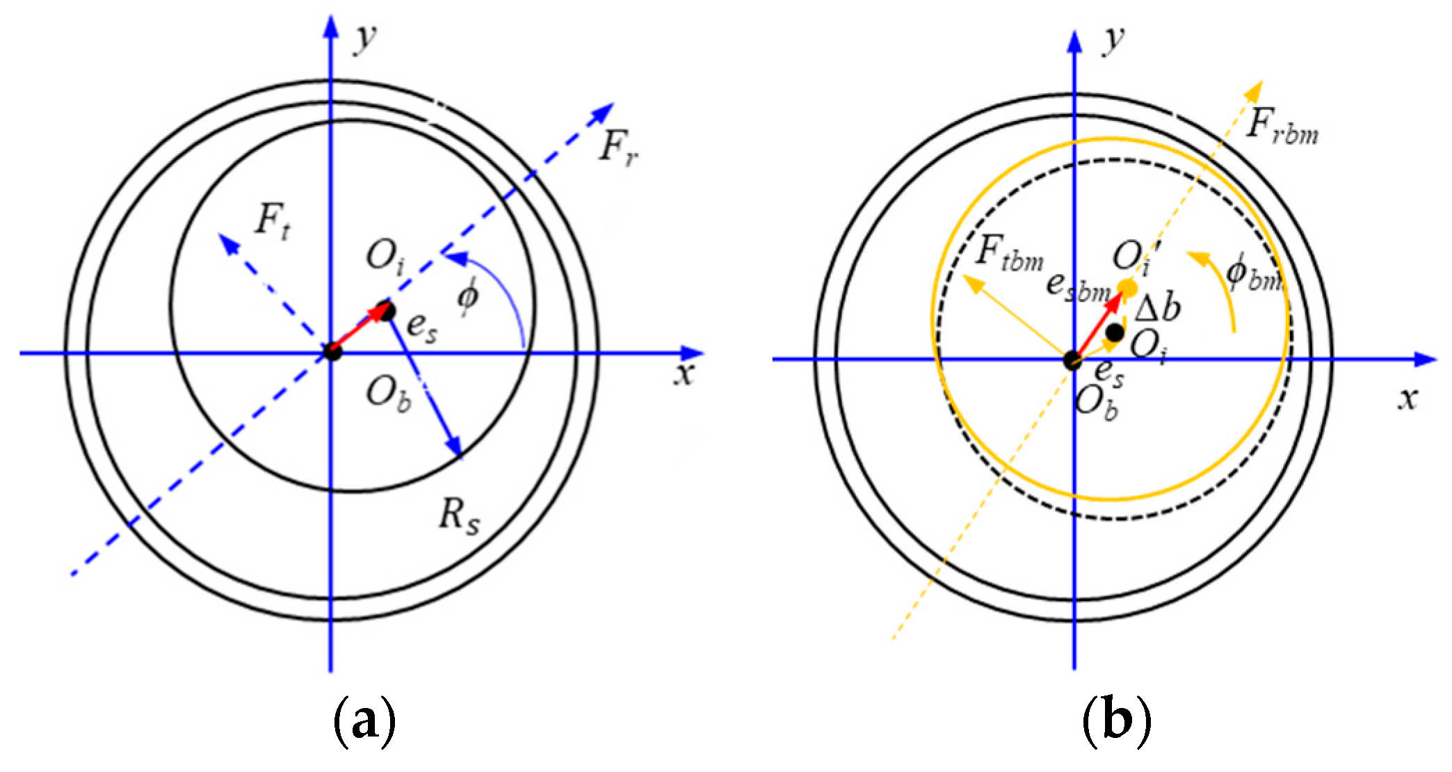
Figure 5a shows the model of the SFD with no bearing misalignment. The polar coordinate of the geometric center Oi of the SFD journal is (es,ϕ), es = (xi2 + yi2)0.5, and ϕ = arctan(yi/xi). xi and yi are the relative displacements of the journal center in the x and y directions, respectively. The radius of the squeeze oil film damper is Rs, and the radial and tangential components of the nonlinear squeeze oil film force are represented as Fr and Ft, respectively. The fixed coordinate system is denoted as Obxy.
Based on the “π” oil film assumption and the short bearing theory, the nonlinear squeeze oil film force of the SFD can be expressed as follows:
F r = μ R s L s 3 c 3 ϕ ˙ e s 2 ε 1 ε 2 2 + e ˙ s π 2 ε 2 + 1 2 1 ε 2 2.5 F t = μ R s L s 3 c 3 ϕ ˙ e s π 2 1 ε 2 1.5 + e ˙ s 2 ε 1 ε 2 2
where μ represents the viscosity of the oil film, Ls is the length of the oil film, c denotes the radial clearance of the SFD, and ϕ’ is the swirling velocity of the journal center. The definitions and calculation formulas for the other symbols can be found in reference [17].
Therefore, the squeeze oil film force of the SFD with no bearing misalignment within the fixed coordinate system Obxy is as follows:
F x = F r cos ϕ F t sin ϕ F y = F r sin ϕ + F t cos ϕ
Figure 5b shows the model of the SFD with the bearing misalignment. The misalignment deformation ∆b of the bearing in No.2 changes the relative displacement of the journal center in the x and y directions, and in turn, the position of Oi of the SFD is changed from (es,ϕ) to (esbm,ϕbm). The formula of (esbm,ϕbm) is as follows:
e s b m = ( x i + b x ) 2 + ( y i + b y ) 2 ϕ s b m = a r c t a n ( y i + b y x i + b x )
where bx and by are the components along the x-axis and y-axis directions of ∆b.
Substitute Equation (11) into Equation (9) and Equation (10); then the squeeze oil film force of the SFD with the support misalignment within the fixed coordinate system Obxy is as follows:
F x b m = F r b m cos ϕ b m F t b m sin ϕ b m F y b m = F r b m sin b m + F t b m cos ϕ b m

2.4. The Dynamic Model of Flexible Discontinuous Rotor Support System with the Support Misalignment

As shown in Figure 6, the aero-engine rotor support system studied in this paper is divided into 47 elements, and the six elements are the curvic couplings C1, C2, C3, C4, C5, and C6. Combining the previously mentioned equivalent model of the curvic coupling, the excitation force model under the support misalignment, and the equivalent mechanical model of combined supports under a support misalignment, the dynamic model of a discontinuous flexible rotor support system with a support misalignment is established:
M r q ¨ + C r + C t + Ω G r q ˙ + K r + K t q = F e + F Y + P T + F b m
where Mr is the mass matrix of the rotor; Cr is the structural damping matrix of the rotor; Kr is the gyroscopic matrix of the rotor; Gr is the stiffness matrix of the rotor; Ct and Kt are the support damping matrix and stiffness matrix of the support system, respectively; and Fe is the unbalance force.

3. The Effect of a Support Misalignment on the Vibration Safety of the Rotor Support System under Ultra-High Operating Speeds

The main influencing factors of the misaligned combined support system are the support stiffness, the support damping, and the amount of the support misalignment. The specific analysis results of the effects of above factors are presented below.

3.1. The Impact of Support Stiffness

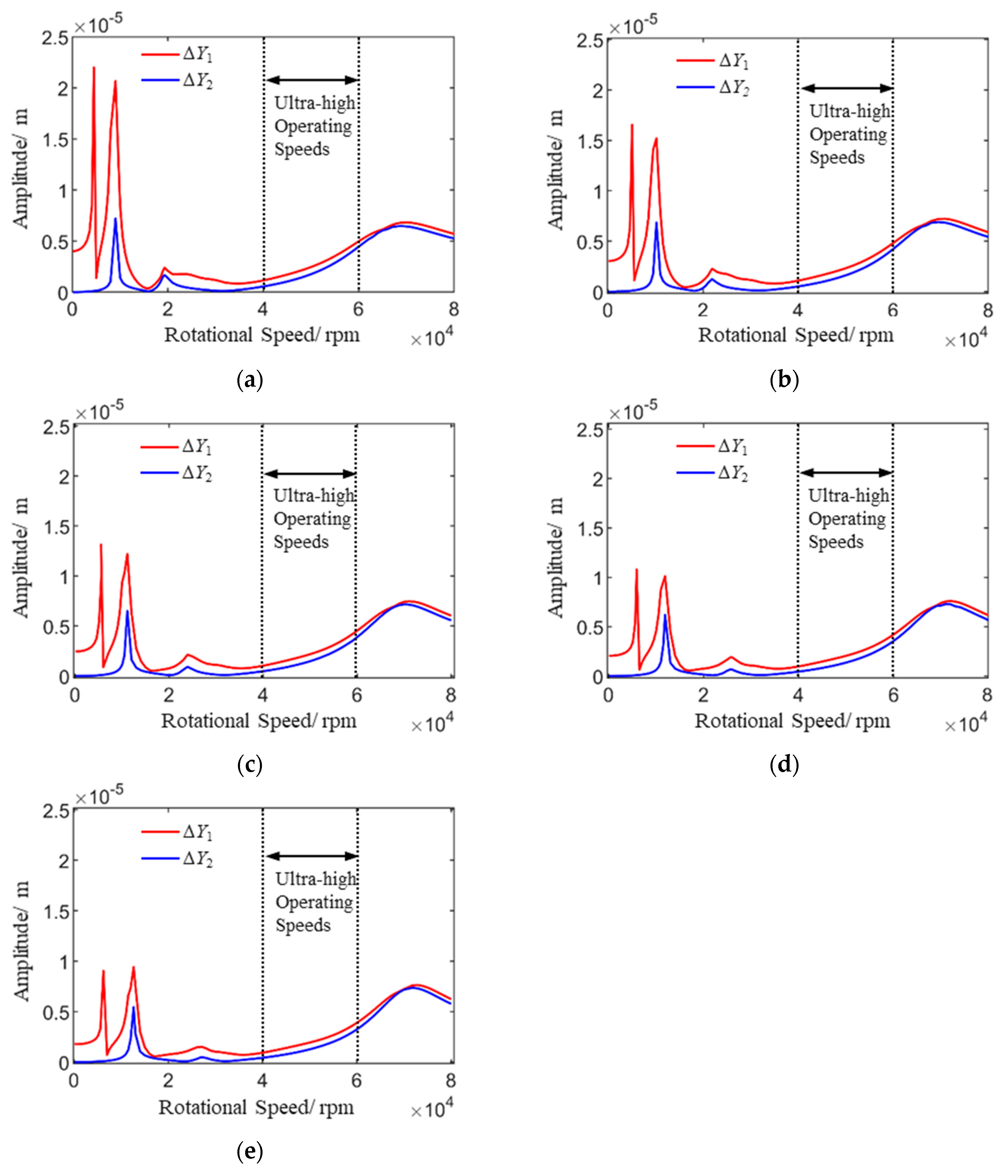
Based on the applicable range of bearing stiffness for the same aero-engine rotor system as described in the literature [18], the range of elastic bearing stiffness is 1.5 × 10⁷ N/m to 3.5 × 10⁷ N/m. Using the dynamic model established in this paper, the dynamic responses of the rotor support system with the support misalignment ∆Y1 (100 μm) and ∆Y2 (0 μm) under different bearing stiffnesses are simulated. The calculation results are shown in Figure 7. According to Figure 7, the amplitude amplification rates of the rotor with the support misalignment ∆Y1, in comparison to the rotor with no support misalignment ∆Y2, are calculated at critical speeds and ultra-high operational speeds under varying support stiffness conditions. The findings are presented in Table 2 and Table 3.
From Figure 7 and Table 2 and Table 3, the following conclusions can be made:
(1)
The support misalignment will cause a new critical speed of the rotor, which is half of the first-order critical speed, and it will also increase the vibration response amplitude of the rotor at each critical speed.
(2)
With the increase in support stiffness, both half of the first-order resonant speed and the first two critical speeds continuously increase, while their amplitudes decrease. The influence of support stiffness and the support misalignment on the third-order resonant speed and amplitude is minimal.
(3)
As the support stiffness increases, the relative change rate of the amplitude in the first critical speed caused by the support misalignment first gradually decreases and then slightly increases when the support stiffness rises from 3 × 10⁷ N/m to 3.5 × 10⁷ N/m. The relative change rate of the amplitude in the second critical speed continuously increases, while the relative change rate of the amplitude in the third critical speed remains basically unchanged. At a support stiffness of 3.5 × 10⁷ N/m, the increase rate of the second-order amplitude caused by misalignment is the highest, approximately 217.60%, as shown in Table 2.
(4)
With the increase in the support stiffness, the vibration amplitude variation rate caused by the support misalignment increases. With the increase of operating speeds, the vibration amplitude variation rate caused by the support misalignment decreases, as shown in Table 2 and Table 3.
(5)
For limiting the vibration response amplitude of the misaligned rotor under ultra-high operating speeds, when the operating speed between from 40,000 rpm to 55,000 rpm, the support stiffness should be set to 3.5 × 10⁷ N/m; and when the operating speed is from 55,000 rpm to 60,000 rpm, the support stiffness should be set to 1.5 × 10⁷ N/m.

3.2. The Impact of Support Damping

For studying the effect of support misalignments on the vibration safety of the flexible discontinuous rotor support system with different support stiffness, dynamic responses of the misaligned rotor system under various damping effects are simulated and calculated based on the dynamic model established in this paper. The calculation results are shown in the figure below.
In Figure 8C1 = 200 N·s/m and C2 = 0 N·s/m—it is evident that the damping only affects the vibration amplitude of the rotor with the support misalignment. For studying the impact of a support misalignment on the damping efficiency of the rotor with a support misalignment, the vibration responses of the discontinuous flexible rotor support system with different damping C1 and C2 are analyzed, and the results are shown in Figure 8. According to Figure 8, the amplitude reduction rates of the rotor with the support misalignment ∆Y1 under the higher support damping C1, in comparison to the rotor with the support misalignment ∆Y1 under the lower support damping C2, are calculated at critical speeds. The findings are presented in Table 4.
From Figure 8 and Table 4, the following conclusions can be drawn:
(1)
The damping only affects the vibration responses of the rotor with the support misalignment. The damping efficiency of the amplitude at different positions of the rotor is different.
(2)
For the amplitude under the first critical speeds, the damping efficiency is generally above 34.86%. The maximum damping efficiency is observed at the center of mass, reaching 42.86%. For the amplitude under the second critical speeds, the damping efficiency is generally above 13.33%. The maximum damping efficiency is observed at the No.1 support, reaching 25.00%. For the amplitude under the third critical speeds, the damping efficiency is generally above 13.05%. The maximum damping efficiency is observed at the No.1 support, reaching 19.77%.
(3)
The damping efficiency of the amplitude at the No.1 support is the largest; in other words, the support misalignment can decrease the damping efficiency of the amplitude. The further away from the misaligned position, the higher the vibration reduction efficiency.
(4)
With the increase of speed, the damping efficiency of the amplitude at the misaligned support (No.2 support) rapidly drops to around 13% and then tends to stabilize; the damping efficiency at the other position continues to decline.

3.3. The Impact of the Amount of Support Misalignments

From the previous research results, the support misalignment led to the increase in the vibration response and the decrease in the damping efficiency, thereby affecting the vibration safety of the rotor system.
The support misalignment has the greatest impact on the vibration response at the second critical speed, the variation law of amplitude and damping efficiency under the second critical speed are the same as those under ultra-high operating speeds
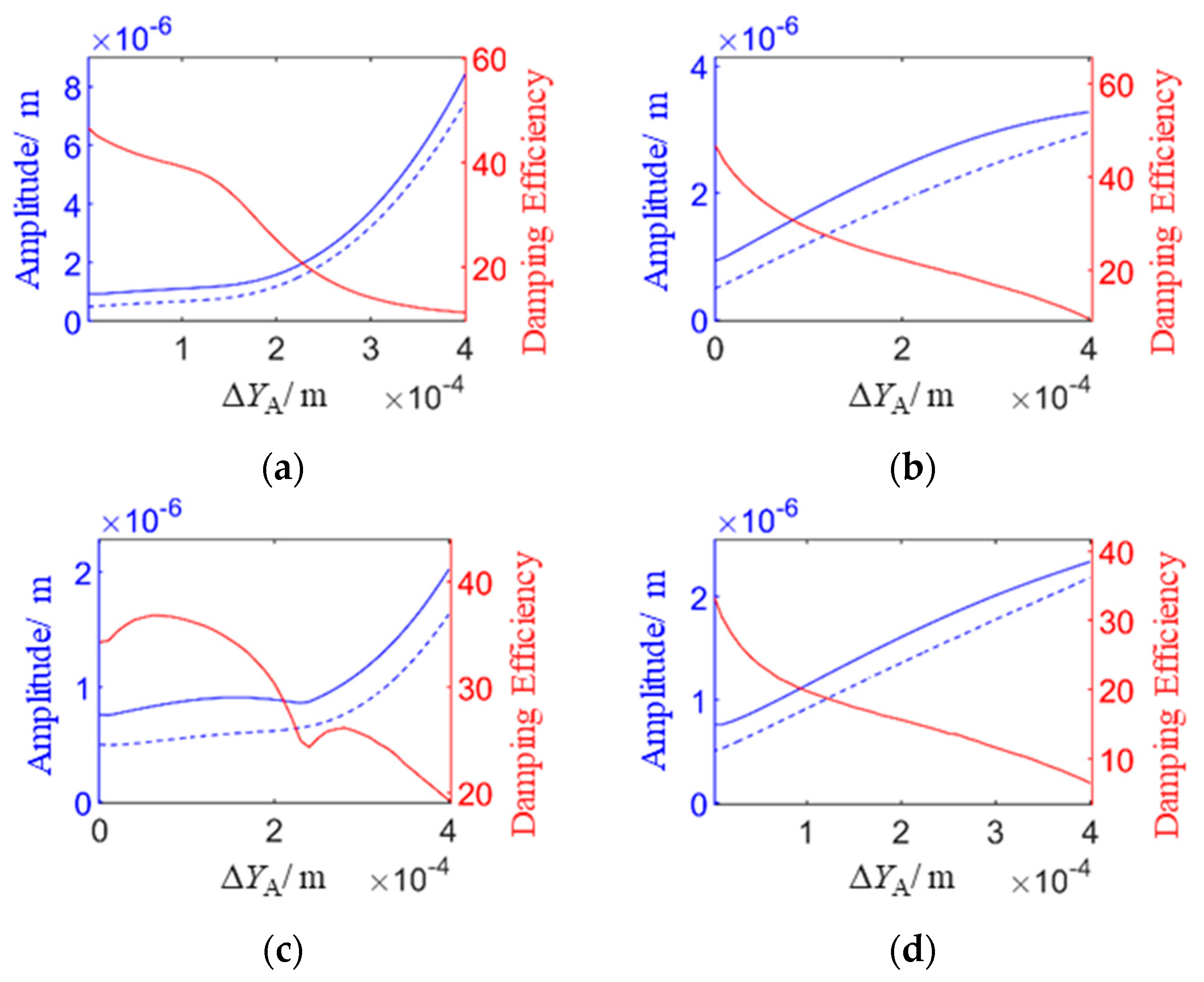
Therefore, the influence of the amount of the support misalignment on the vibration response and damping efficiency under the second critical speed is studied, and the results are shown in Figure 9 and Figure 10.
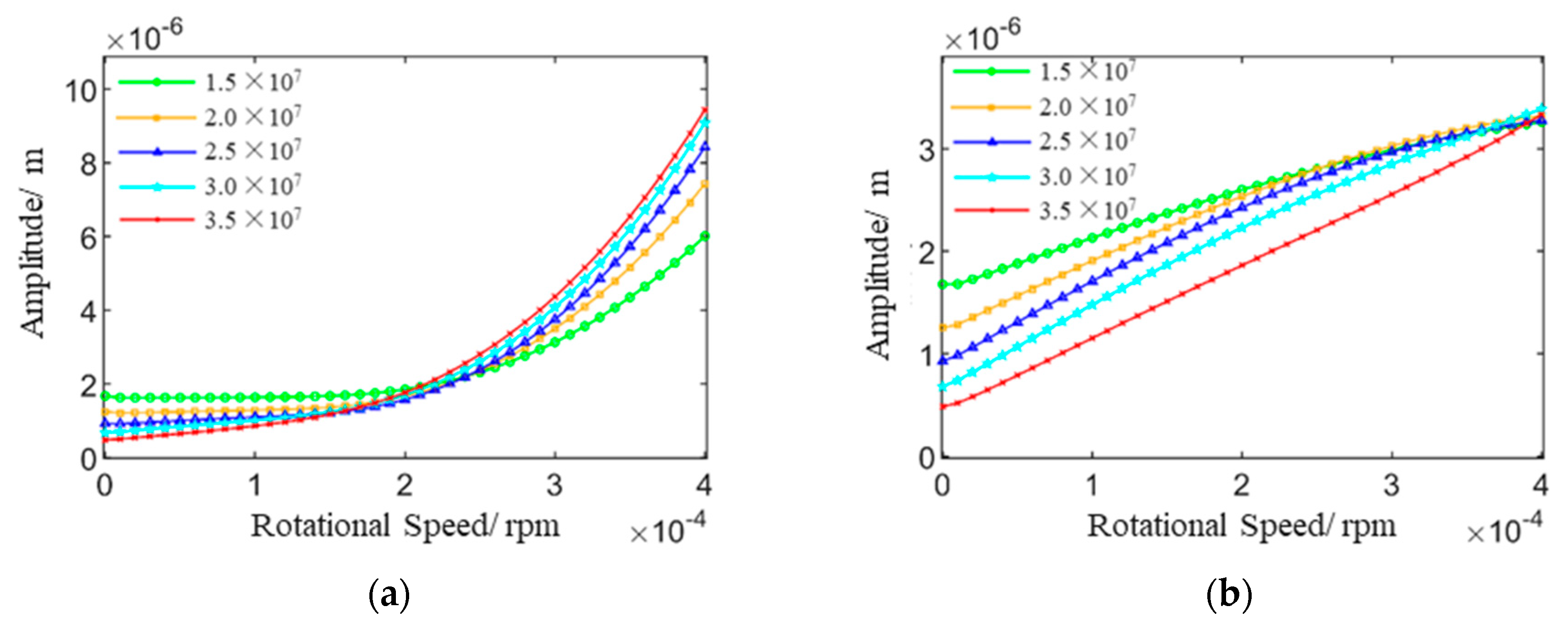
Figure 9 shows the vibration displacements in the x and y directions under the second critical speed when the support stiffness varies from 1.5 × 10⁷ N/m to 3.5 × 10⁷ N/m, and the amount of the support misalignment ranges from 0 to 400 μm.
According to Figure 9, the following conclusions can be drawn:
(1)
When the misalignment is less than 150 μm, the larger the support stiffness, the larger the vibration displacement in the x direction. Conversely, when the misalignment is more than 250 μm, the larger the support stiffness, the smaller the vibration displacement in the x direction.
(2)
The vibration displacement in the y direction decreases with the increase of the support stiffness when the misalignment is less than 400 μm. When the misalignment is 400 μm, the amplitudes with different support stiffnesses are basically the same.
Figure 10 shows the vibration displacements and the damping efficiency at the two supports under the second critical speed with C1 and C2. The solid blue line represents the vibration displacements with C2, the dashed blue line represents the vibration displacements with C1, and the solid red line represents the damping efficiency.
According to Figure 10, the following conclusions can be drawn:
(1)
The vibration reduction efficiency of the maximum vibration displacements in the x and y directions at the No.1 support decreases continuously with the increase of the misalignment, and the reduction is significant, dropping from about 46%, when aligned, to around 10%, when misaligned by 400 μm.
(2)
The vibration reduction efficiency of the maximum vibration displacements in the x direction at the No.2 support first increases, then decreases, and then increases again with the increase in misalignment, while in the y direction, it continuously decreases. When aligned, the vibration reduction efficiency at the No.2 support is approximately 34% in both the x and y directions. When misaligned by 400 μm, the efficiency in the x direction is 19.3%, while in the y direction, it is only 6.5%.
From the above analysis, it can be concluded that:
(1)
The misalignment increases the vibration response of the rotor, reduces the vibration reduction efficiency of the support system, and consequently decreases the vibration safety of the rotor support system.
(2)
When the misalignment is uncertain, a smaller support stiffness should be chosen within the applicable range of support stiffness. For the same degree of support misalignment, the smaller the support stiffness, the smaller the increase in amplitude caused by the support misalignment, resulting in higher vibration safety for the rotor.
(3)
When the misalignment amount is determined, if the support misalignment is less than 150 μm, the support stiffness should be set at 3.5 × 10⁷ N/m for minimal rotor amplitude; if the support misalignment is from 150 μm to 250 μm, the support stiffness 2.5 × 10⁷ N/m minimizes the rotor amplitude; if the support misalignment is from 250 μm to 400 μm, the support stiffness of 1.5 × 10⁷ N/m minimizes the rotor amplitude.

3.4. Experimental Validation

In the previous section, the impact of the support misalignment on the vibration safety of the rotor-support system was studied through the simulation. The influence of a support misalignment on the dynamic characteristics is investigated by using the established experimental bench, for validating the previous research results.
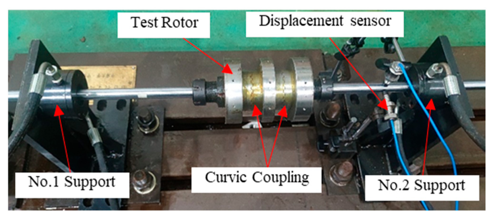
The rotor support system test bench is shown in Figure 11. The test bench consists of the test rotor with curvic couplings, the combined support made up of SCES and SFD, and signal acquisition and analysis equipment such as sensors.
Based the modeling method presented in this paper, the finite element model of the test rotor system is established and shown in Figure 12. The first three critical speeds of the test rotor are calculated using the finite element model, and the results are shown in Table 5.
For measuring the vibration reduction efficiency at the No.2 support of the rotor under different misalignment conditions, the specific experimental steps are as follows:
The critical speed and vibration response of the rotor are measured; the test operations are as follows:
Step (1). Assemble the test rotor support system and arrange displacement sensors in the x and y directions at a position near the No.2 support. Connect the sensors to the signal acquisition device. Use the three-point dynamic balancing method to control the unbalance mass to 20 g·mm.
Step (2). As shown in Table 5, the second critical speed of the test rotor is 1350 r/min. For the safety of the experiment, the rotational speed is set to 1200 r/min, which is close to the second critical speed of the test rotor.
Step (3). Set the oil pressure of the combined support to 10 MPa, as shown in Figure 13a, then collect the vibration displacement signal of the aligned rotor.
Step (4). Adjust the oil pressure of the combined support to 0 MPa and collect the vibration displacement signal of the aligned rotor again.
Step (5). Use shims with a thickness of 0.1 mm to change the misalignment amount at the No.2 support to 0.1 mm, 0.2 mm, 0.3 mm, 0.4 mm, and 0.5 mm, as shown in Figure 13b. Repeat steps 2 and 4 to measure the rotor vibration displacement signals under different misalignment amounts.
Step (6). Store and export the experimental data for post-processing.
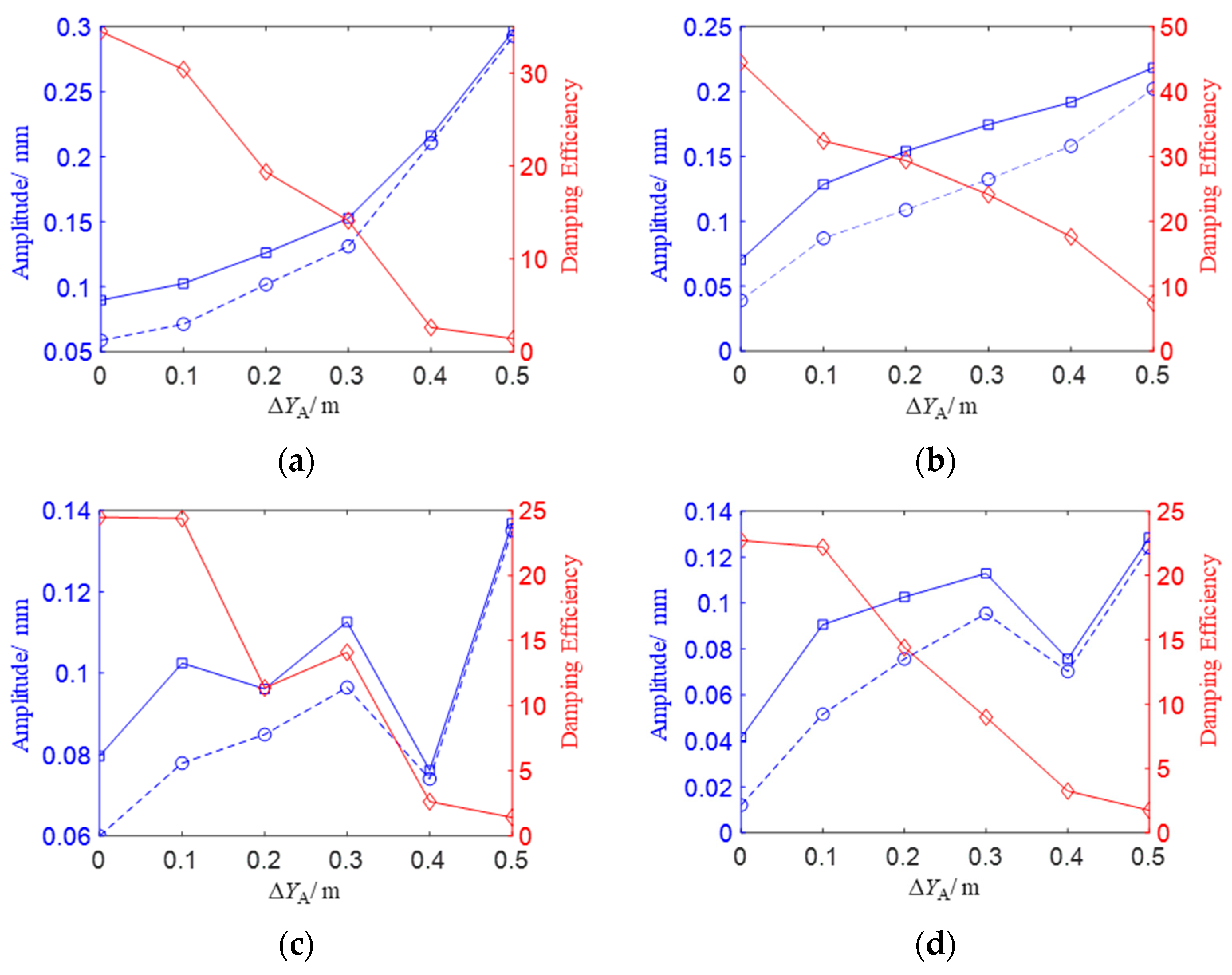
The test results are shown in Figure 14.
Figure 14 shows the vibration displacements and damping efficiency at the No.1 support and the No.2 support when the oil film pressure is 0 Mpa or 10 MPa. The blue solid line represents the vibration displacements with an oil pressure of 0 MPa, while the blue dashed line represents the vibration displacements with an oil pressure of 10 MPa. The red solid line indicates the damping efficiency.
From the test results shown in Figure 14, the following conclusions can be drawn:
(1)
As the misalignment increases from 0 to 0.5 mm, the amplitudes in both the x and y directions at the No.1 support increase, while the vibration reduction efficiency declines.
(2)
When the misalignment increases from 0 to 0.1 mm, the damping efficiency in the x direction at the No.2 support remains unchanged. As the misalignment increases from 0.1 mm to 0.2 mm, the damping efficiency in the x direction at the No.2 support decreases. Then, when the misalignment increases from 0.2 mm to 0.3 mm, the damping efficiency in the x direction at the No.2 support rises again. However, as the misalignment increases from 0.3 mm to 0.5 mm, the damping efficiency at the No.2 support first rises and then falls, and the damping efficiency in the y direction continuously decreases.
(3)
When the misalignment is 0, the oil film damping efficiency of vibration displacement in both x and y directions at the No.2 support is about 25%. When the misalignment is 0.5 mm, the damping efficiency in both x and y directions is only about 2%. The damping efficiency of the support system is reduced by the support misalignment; the greater the misalignment, the worse the damping effect of the support system.
By comparing the experimental results with the simulation results, it can be concluded that the trend of the damping efficiency and the vibration displacement at the misaligned support obtained by the experiment is the same as those obtained by the simulation, which verifies the correctness and reasonableness of the study presented in this paper.

4. Conclusions

(1)
This paper establishes a dynamic model of a flexible discontinuous rotor support system with a certain type of aero-engine rotor system as the object of study. The effects of flexibility deformation under ultra-high rotational speeds, discontinuous characteristics, and the characteristics of misaligned combined support with SFD and SCES are taken into account. The model established in this paper provides an important theoretical foundation for the dynamic analysis and vibration safety design of the next generation of aero-engine rotors.
(2)
Based on the established dynamic model, the influence of the support stiffnesses on the vibration characteristics of the aero-engine rotor support system with the support misalignment under ultra-high rotational speeds is investigated. With the increase of the support stiffness, the vibration amplitude variation rate caused by the support misalignment increases. With the increase of operating speeds, the vibration amplitude variation rate caused by the support misalignment decreases. For limiting the vibration response amplitude of the misaligned rotor under ultra-high operating speeds, when the operating speed is from 40,000 rpm to 55,000 rpm, the support stiffness should be set to 3.5 × 10⁷ N/m; when the operating speed is from 55,000 rpm to 60,000 rpm, the support stiffness should be set to 1.5 × 10⁷ N/m.
(3)
Based on the established dynamic model, the influence of the support damping on the vibration characteristics of the aero-engine rotor support system with the support misalignment under ultra-high rotational speeds is investigated. The damping only affects the vibration responses at of the rotor with a support misalignment. The damping efficiency of the amplitude at different positions of the rotor is different. The support misalignment can decrease the damping efficiency of the amplitude. The further away from the misaligned position, the higher the vibration reduction efficiency.
(4)
Based on the established dynamic model, the influence of the misalignment amount on the vibration characteristics of the aero-engine rotor support system with a support misalignment under ultra-high rotational speeds is investigated.
The misalignment increases the vibration response of the rotor, reduces the vibration reduction efficiency of the support system, and consequently decreases the vibration safety of the rotor support system. When the amount of misalignment is uncertain, a smaller support stiffness should be chosen within the applicable range of support stiffnesses. When the misalignment amount is determined, if the support misalignment is less than 150 μm, the support stiffness should be set at 3.5 × 10⁷ N/m for minimal rotor amplitude; if the support misalignment is from 150 μm to 250 μm, a support stiffness of 2.5 × 10⁷ N/m minimizes the rotor amplitude; and if the support misalignment is from 250 μm to 400 μm, a support stiffness of 1.5 × 10⁷ N/m minimizes the rotor amplitude.

Author Contributions

A.W. designed the research plan; X.H. proposed the solution method, the testing work, and wrote this paper; H.Z. processed the data and proposed the testing work; W.Z. completed the simulation and established the model. All authors consented to the paper’s submission to the journal. All authors have read and agreed to the published version of the manuscript.

Funding

This project was supported in part by the State Key Laboratory of Precision Manufacturing for Extreme Service Performance Foundation Project (No. ZZYJKT2021-07).

Institutional Review Board Statement

Not applicable.

Informed Consent Statement

Not applicable.

Data Availability Statement

Data are contained within the article.

Acknowledgments

Ailun Wang and the co-authors would like to thank all the reviewers who participated in the review of this manuscript.

Conflicts of Interest

The authors declare no conflicts of interest.

References

  1. Wang, P.; Xu, H.; Ma, H.; Yang, Y. Research on the dynamic characteristics of a planetary gear system-rotor system with bearing tilt misalignment. J. Vib. Eng. 2011, 36, 116–127. [Google Scholar]
  2. Rybczyński, J. The possibility of evaluating turbo-set bearing misalignment defects on the basis of bearing trajectory features. Mech. Syst. Signal Process. 2011, 23, 521–536. [Google Scholar] [CrossRef]
  3. Gibbons, C.B. Coupling misalignment force. In Proceedings of the 5th Turbomachinery Symposium; Texas A&M University: College Station, TX, USA, 1976. [Google Scholar]
  4. Shentu, L.; Zhao, Q.; Yang, P.; Qing, S.; Sun, Y. Nonlinear Dynamics Analysis of Diaphragm Coupling Systems with Angular Misalignment. J. Mech. Strength 2018, 40, 552–558. [Google Scholar]
  5. Li, H. Research on Nonlinear Vibration Characteristics of Ball Bearing-Misaligned Rotor System. Ph.D. Thesis, School of Astronautics, Harbin Institute of Technology, Harbin, China, 2005. [Google Scholar]
  6. Bouaziz, S.; Hili, M.A.; Mataar, M.; Fakhfakh, T.; Haddar, M. Dynamic behaviour of hydrodynamic journal bearings in presence of rotor spatial angular misalignment. Mech. Mach. Theory 2009, 44, 1548–1559. [Google Scholar] [CrossRef]
  7. Li, J.; Cao, S.; Guo, H. Effects of Surface Waviness of Intershaft Bearing on Dynamic Characteristics of Dual Rotor System. Mech. Sci. Technol. 2019, 39, 1794–1804. [Google Scholar]
  8. Ertas, B.H.; Vance, J.M. Effect of static and dynamic misalignment on ball bearing radial stiffness. J. Propuls. Power 2004, 20, 634–647. [Google Scholar] [CrossRef]
  9. Al-Hussain, K.M.; Redmond, I. Dynamic response of two rotors connected by rigid mechanical coupling with parallel misalignment. J. Sound Vib. 2002, 249, 483–498. [Google Scholar] [CrossRef]
  10. Zhang, Z.; Ma, Y.; Li, J.; Hong, J. Research on The Dynamic Model of Aero-Engine Rotors. Eng. Mech. 2014, 31, 208–214. [Google Scholar]
  11. Zhao, G.; Wang, T.; Li, S.; Li, F.; Ma, W. Theoretical and experimental study on dynamics of a statically indeterminate rotor system with misalignment. J. Vib. Shock 2024, 40, 159–165. [Google Scholar]
  12. Zhang, L.; Wei, J.; Wang, X.; Zhang, J.; Ma, Z.; Deng, X. Vibration characteristics of misalignment-rubbing coupling fault for an axial-flow hydro-generator unit. J. Vib. Shock 2021, 43, 11–18. [Google Scholar]
  13. Wang, P.; Xu, H.; Ma, H.; Han, H.; Yang, Y. Effects of three types of bearing misalignments on dynamic characteristics of planetary gear set-rotor system. Mech. Syst. Signal Process. 2014, 169, 108736. [Google Scholar] [CrossRef]
  14. Yang, Z. The Influence of Pre-Tightening Force on the Dynamic Characteristics of the Curvic Couplings—Central Tie Rod Rotor System. Master’s Thesis, Central South University, Changsha, China, 2020. [Google Scholar]
  15. Li, Y.; Guan, Y.; Li, T.; Li, X. A Fast Analytical Method for The De-formation of Beams with Varying Cross-Sections. Eng. Mech. 2015, 32, 116–121. [Google Scholar]
  16. Committee of Editors of the Aircraft Engine Design Handbook. Aircraft Engine Design Handbook, Volume 19: Rotor Dynamics and Whole Engine Vibration; Aviation Industry Press: Beijing, China, 2000; pp. 208–226. [Google Scholar]
  17. Liu, Z.; Liao, M.; Cong, P.; Wang, J.; Wang, S.; Shi, B.; Li, Y. Design method of squeeze film damper for aero-engine rotors. J. Aerosp. Power 2015, 30, 2762–2770. [Google Scholar]
  18. Wang, L. Dynamic Modeling and Vibration Characteristics Research of Com-Plex Variable-Section Aeroengine Rotors with Curvic Couplings. Ph.D. Thesis, Central South University, Changsha, China, 2022. [Google Scholar]
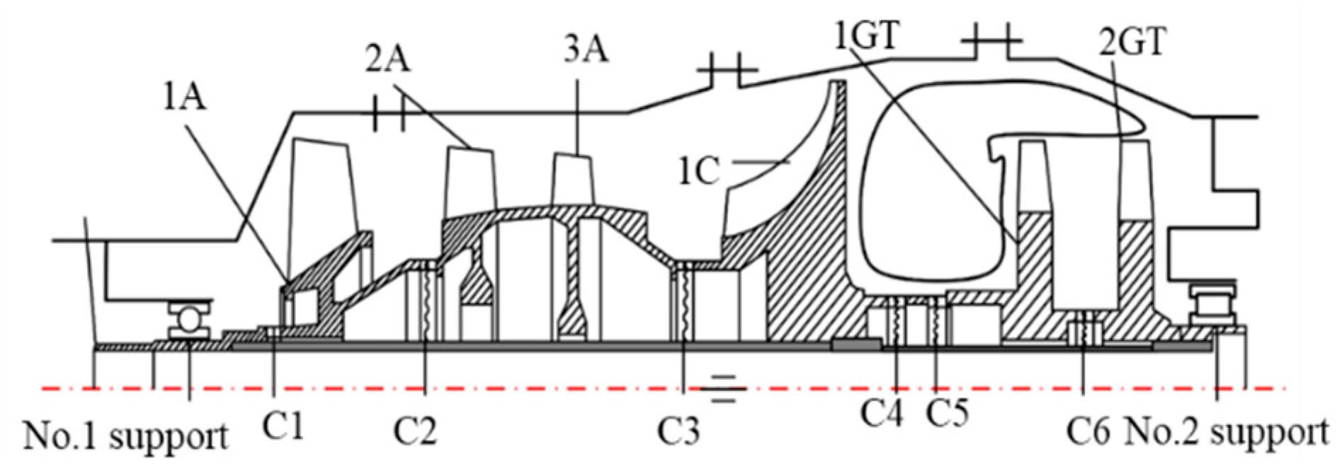
Figure 1. Schematic diagram of the typical aero-engine rotor support system.
Machines 12 00669 g001
Figure 2. The schematic diagram of the curvic coupling and its equivalent model.
Machines 12 00669 g002
Figure 3. The schematic diagram of the effect of the bending deformation of misaligned flexible rotors under ultra-high operating speeds on excitations and the driving torque. (a) The effect on excitations. (b) The effect on the torque.
Machines 12 00669 g003
Figure 4. The schematic diagram of the combined support system with SFD and SCES. (a) The structure of the combined support system. (b) The equivalent mechanical model of the combined support system.
Machines 12 00669 g004
Figure 5. The mechanical model of the squeeze oil film force. (a) The model with no misalignment. (b) The model with the support misalignment.
Machines 12 00669 g005
Figure 6. The dynamic model of discontinuous flexible rotor support system with a support misalignment.
Machines 12 00669 g006
Figure 7. Vibration responses of the discontinuous flexible rotor support system with different support misalignments under different support stiffnesses. (a) 1.5 × 10⁷ N/m. (b) 2 × 10⁷ N/m. (c) 2.5 × 10⁷ N/m. (d) 3 × 10⁷ N/m. (e) 3.5 × 10⁷ N/m.
Machines 12 00669 g007
Figure 8. Vibration responses of the discontinuous flexible rotor support system with different damping C1 and C2. (a) Vibration responses at the No.1 support with ∆Y1 (100 μm). (b) Vibration responses at the center of mass with ∆Y1 (100 μm). (c) Vibration responses at the No.2 support with ∆Y1 (100 μm).
Machines 12 00669 g008
Figure 9. The vibration displacements in the x and y directions at the second critical speed. (a) The displacements in the x direction. (b) The displacements in the y direction.
Machines 12 00669 g009
Figure 10. The vibration displacements and the damping efficiency at the No.1 support and the No.2 support with C1 and C2. (a) The damping efficiency and the displacement in the x direction at the No.1 support. (b) The damping efficiency and the displacement in the y direction at the No.1 support. (c) The damping efficiency and the displacement in the x direction at the No.2 support. (d) The damping efficiency and the displacement in the y direction at the No.2 support.
Machines 12 00669 g010
Figure 11. Schematic diagram of the rotor support system test bench.
Machines 12 00669 g011
Figure 12. The finite element model of the test rotor system.
Machines 12 00669 g012
Figure 13. Schematic diagram of experimental operations. (a) The adjustment of oil pressure. (b) The adjustment of the misalignment by skims.
Machines 12 00669 g013
Figure 14. The experimental results of vibration displacements and damping efficiency in x and y directions at the No.1 support and the No.2 support with different oil pressures. (a) The displacements and damping efficiency in the x direction at No.1 support. (b) The displacements and damping efficiency in the y direction at the No.1 support. (c) The displacements and damping efficiency in the x direction at the No.2 support. (d) The displacements and damping efficiency in the y direction at the No.2 support.
Machines 12 00669 g014
Table 1. The parameters of the equivalent model of six curvic couplings.
NameEquivalent Elastic Modulus
(Gpa)
Equivalent Density
(kg/m3)
Poisson’s Ratio
C173.804401.070.3
C268.644347.210.3
C372.934366.700.3
C4155.766130.610.3
C5220.387906.390.3
C6211.667886.850.3
Table 2. The amplitude variation rate under the first three critical speeds.
Parameter Name1st
Critical Speed
2nd
Critical Speed
3rd
Critical Speed
1.5 × 10⁷ N/m191.34%50.56%6.02%
2.0 × 10⁷ N/m130.45%92.46%4.84%
2.5 × 10⁷ N/m96.93%137.71%4.69%
3.0 × 10⁷ N/m75.14%192.45%5.87%
3.5 × 10⁷ N/m84.08%217.60%6.15%
Table 3. The amplitude variation rate under ultra-high operating speeds.
Parameter Name40,000 rpm45,000 rpm50,000 rpm55,000 rpm
1.5 × 10⁷ N/m100.00%54.54%33.33%25.93%
2.0 × 10⁷ N/m116.67%41.67%35.29%22.22%
2.5 × 10⁷ N/m115.49%56.78%38.37%26.43%
3.0 × 10⁷ N/m120.00%55.56%53.85%30.00%
3.5 × 10⁷ N/m99.99%65.00%38.46%31.58%
Table 4. The damping efficiency of the first three critical speeds.
Parameter Name1st Critical Speed2nd Critical Speed3rd Critical Speed
No.1 Support41.18%25.00%19.77%
Center of mass.42.86%--16.00%
No.2 Support34.86%13.33%13.05%
Table 5. The first three critical speeds of the test rotor system.
1st Critical Speed2nd Critical Speed3rd Critical Speed
405 r/min1350 r/min4135 r/min
Disclaimer/Publisher’s Note: The statements, opinions and data contained in all publications are solely those of the individual author(s) and contributor(s) and not of MDPI and/or the editor(s). MDPI and/or the editor(s) disclaim responsibility for any injury to people or property resulting from any ideas, methods, instructions or products referred to in the content.