
The Selection of Cutting Speed to Prevent Deterioration of the Surface in Internal Turning of C45 Steel by Small-Diameter Boring Bars

 ,
,  , , ,
, , ,  ,
,
Abstract
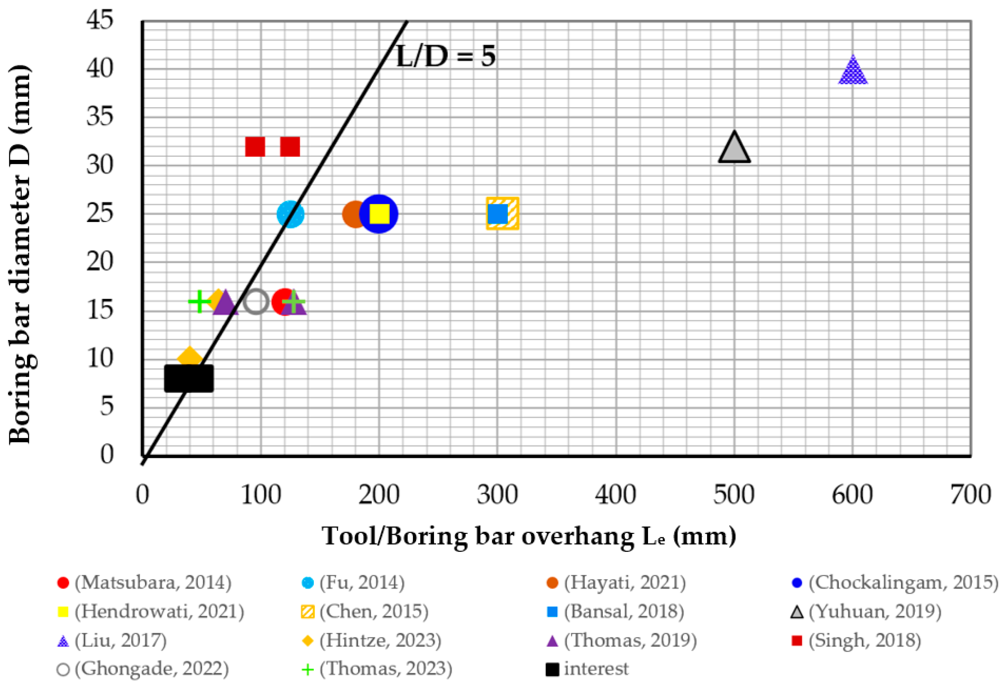
1. Introduction
2. Materials and Methods
2.1. Selected Cutting Tools and Workpiece Material
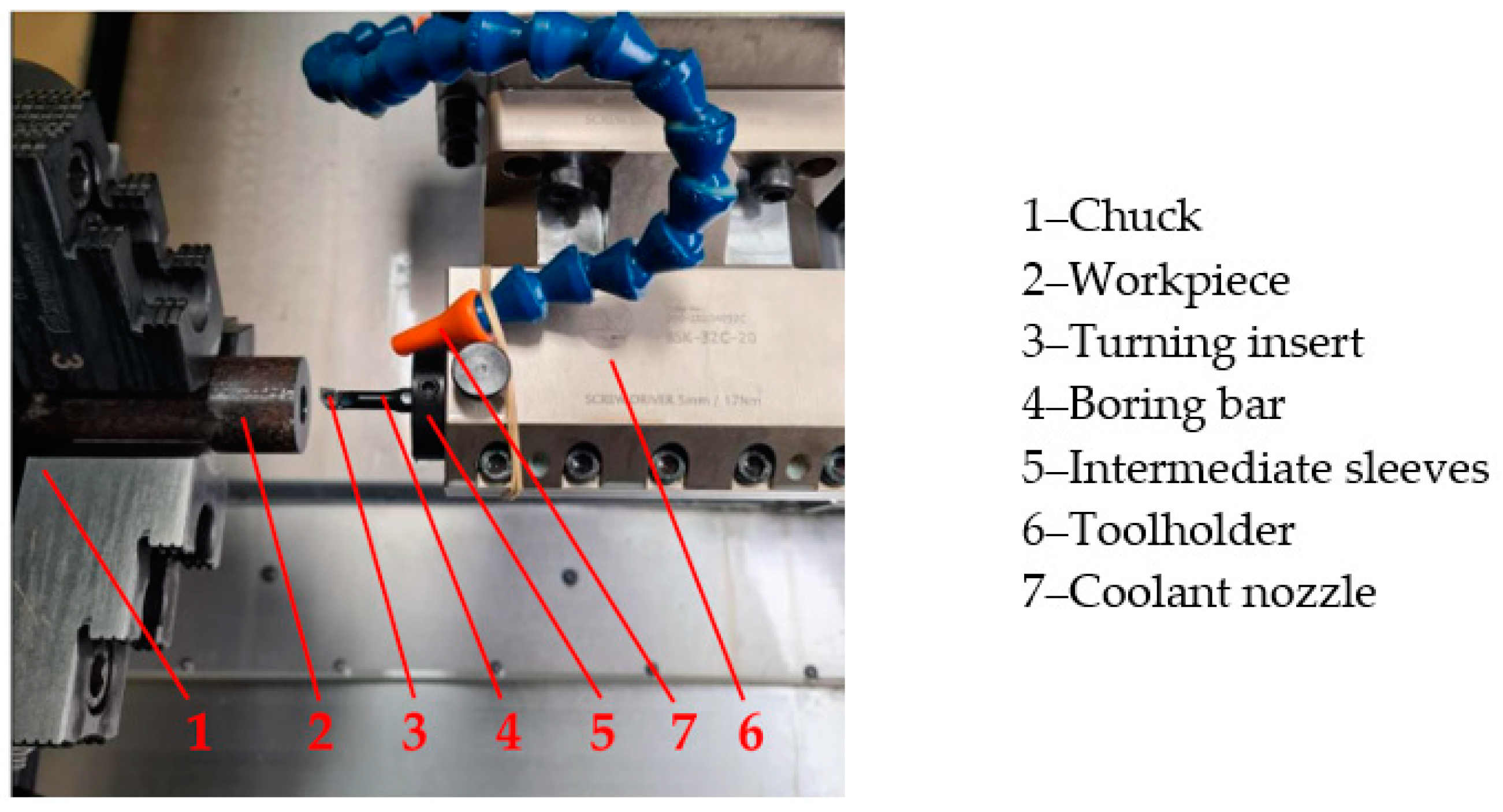
2.2. Cutting Tests
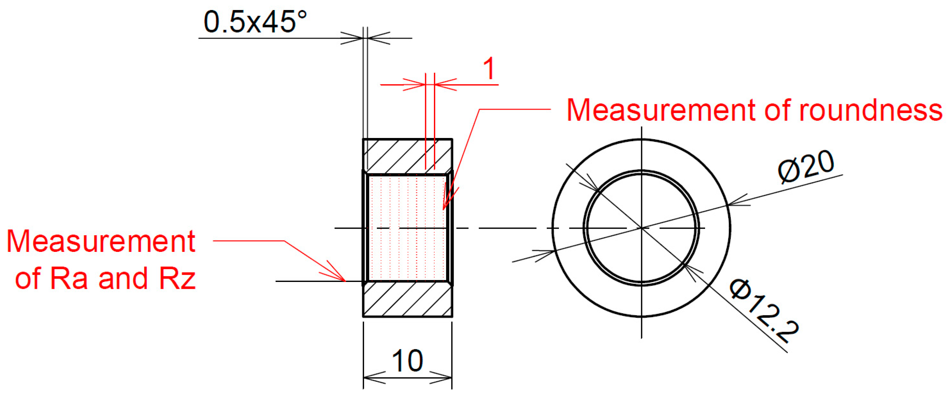
2.3. Measurement of Surface Roughness Parameters Ra, Rz
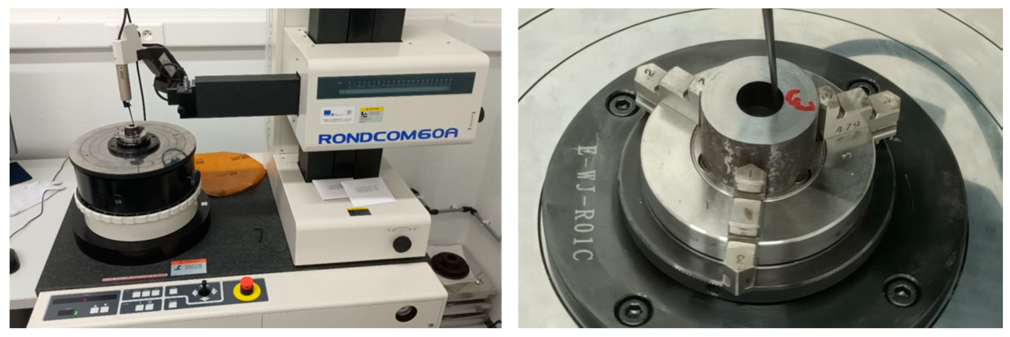
2.4. Measurement of Roundness
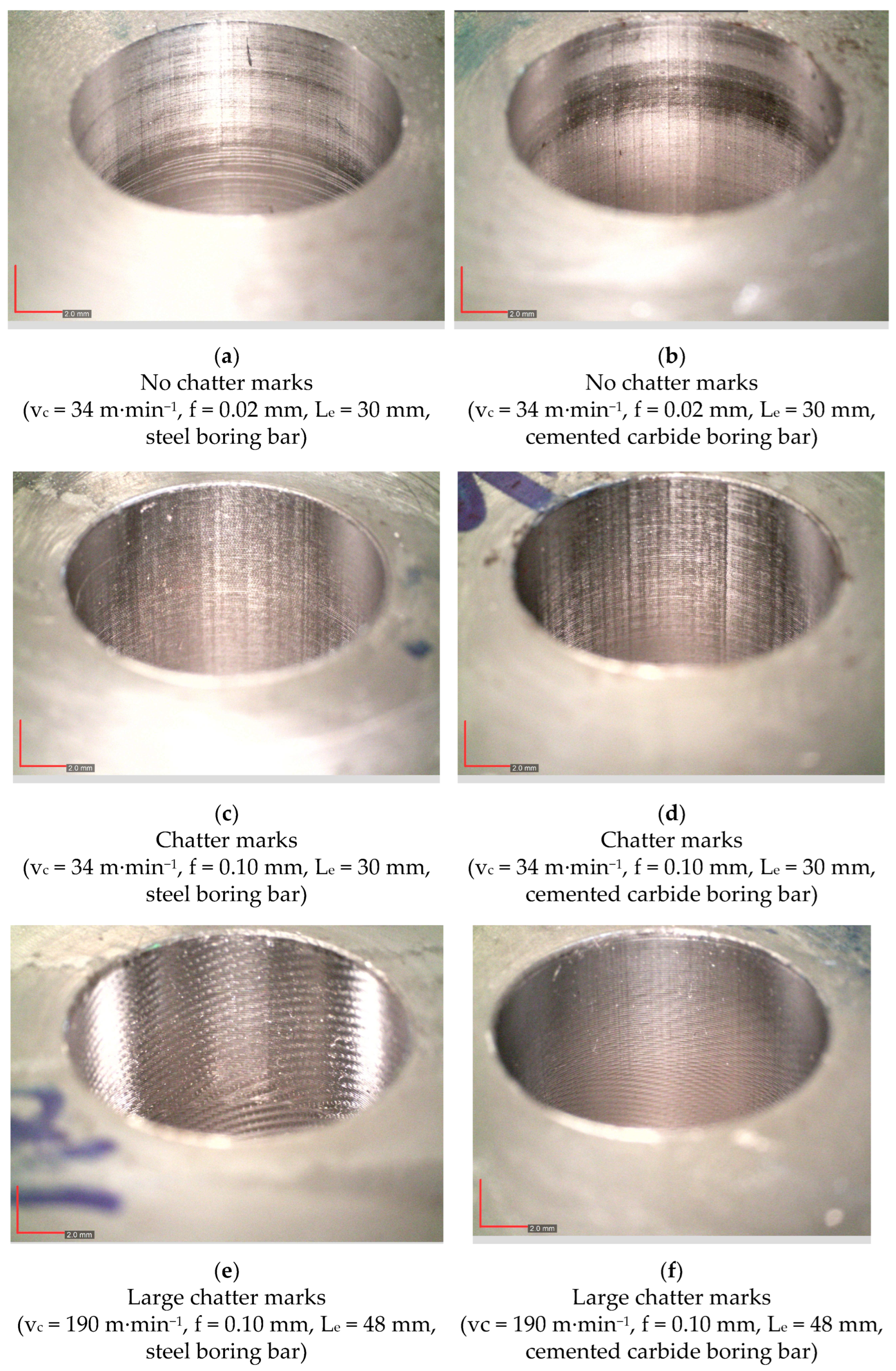
3. Results and Discussion
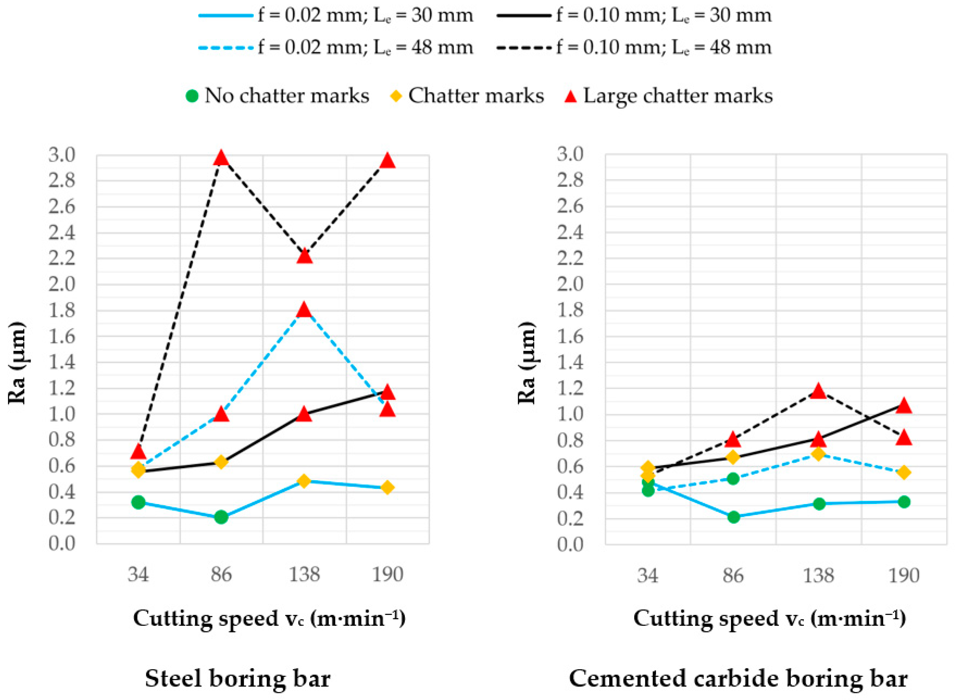
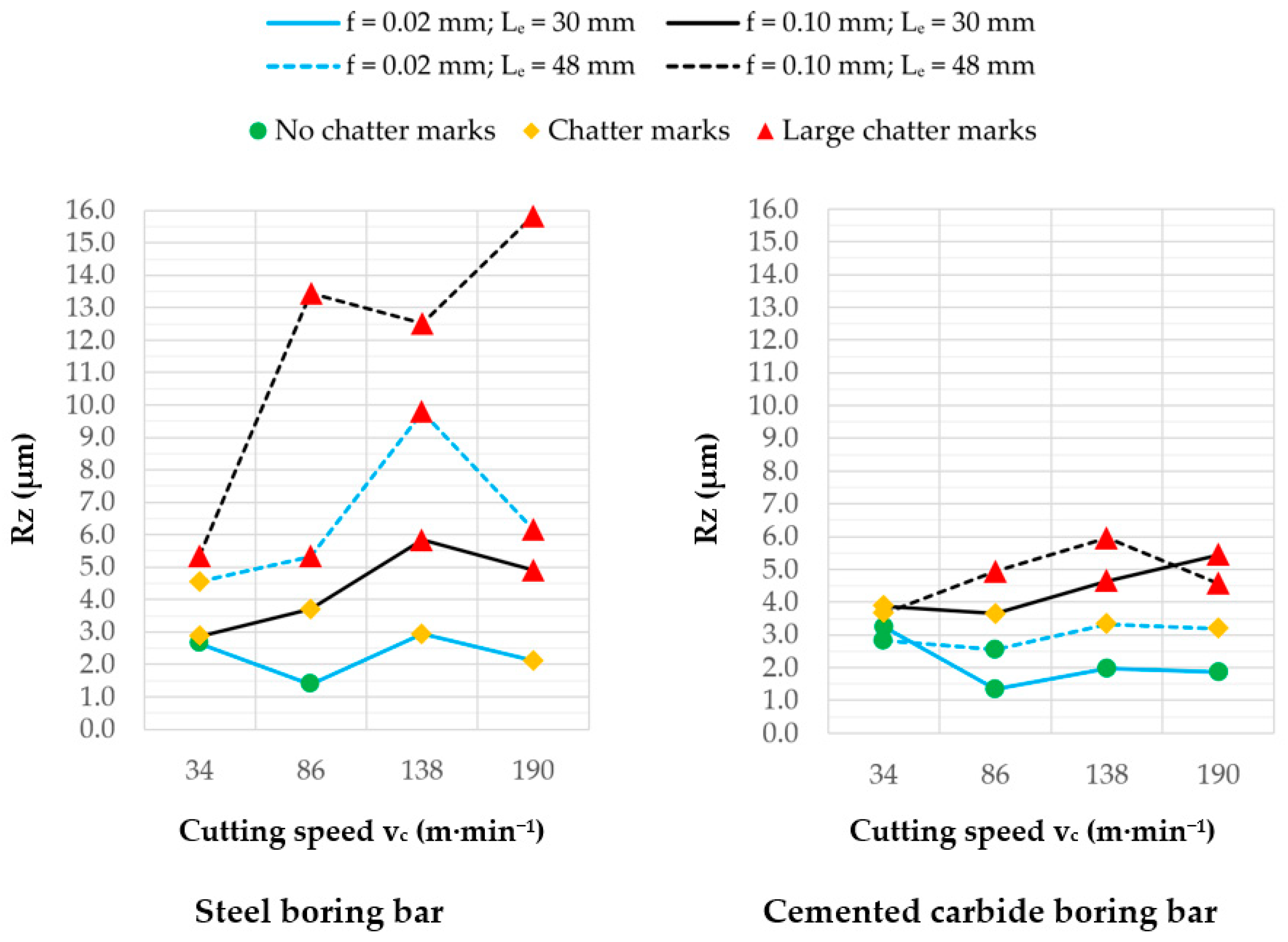
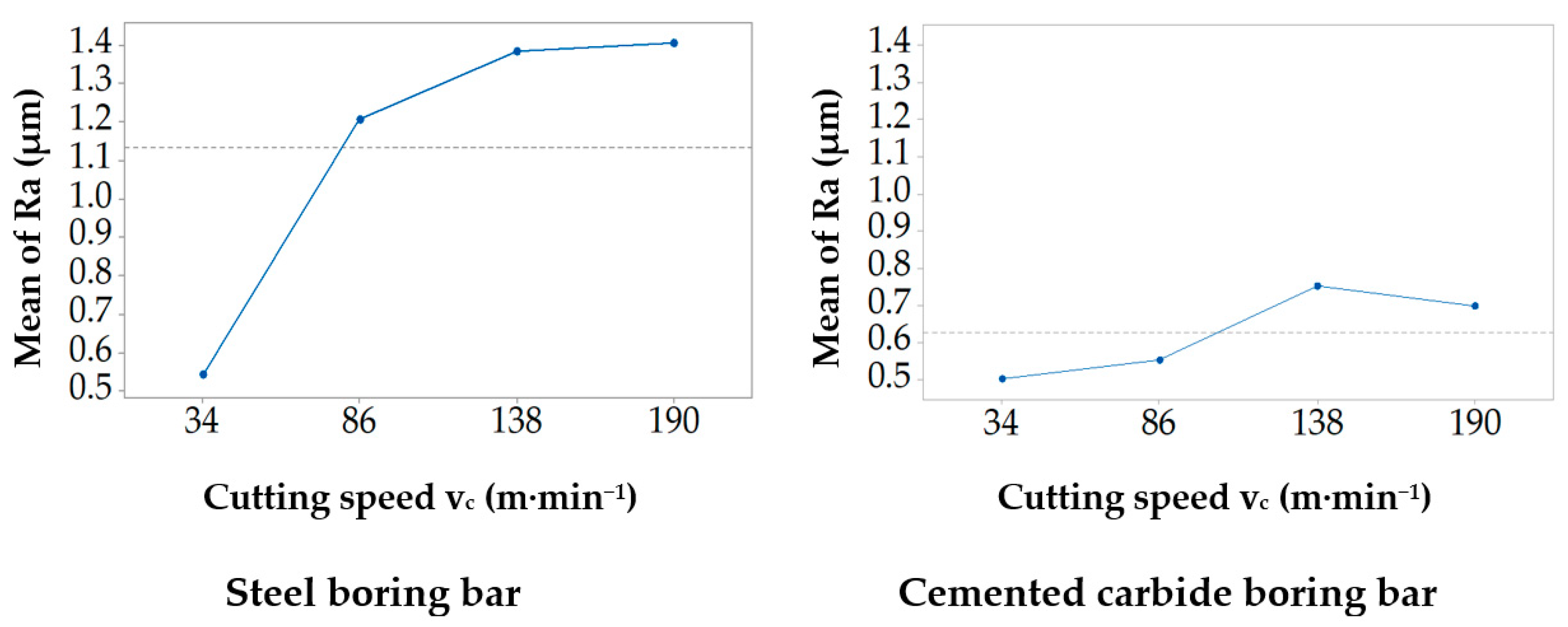
3.1. Surface Roughness
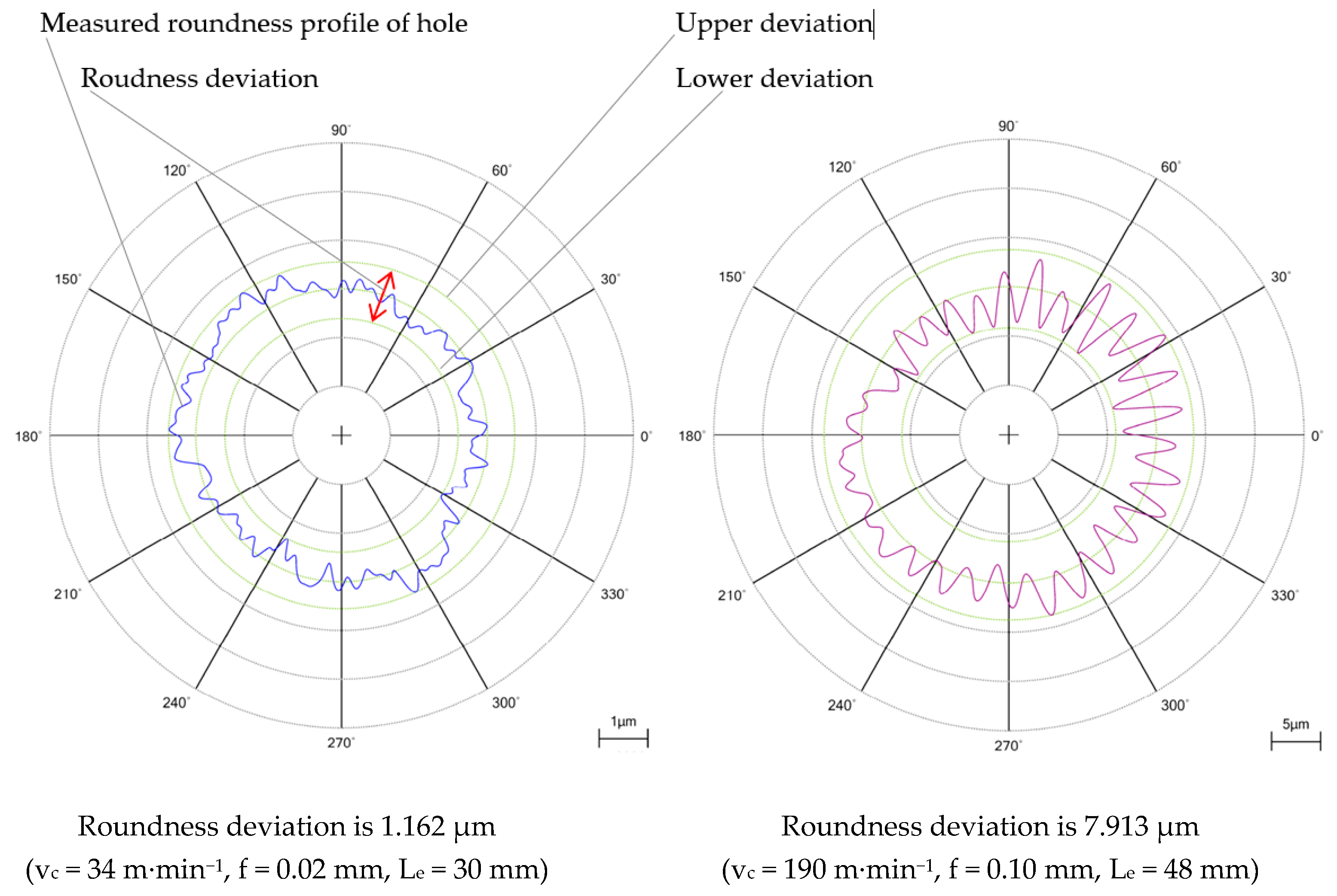
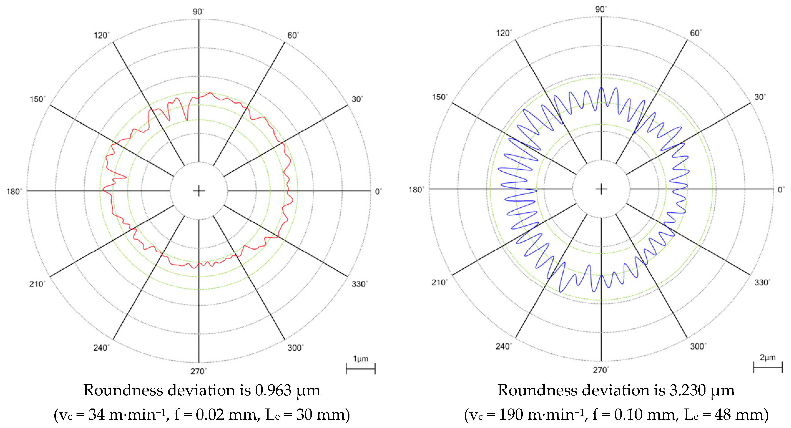
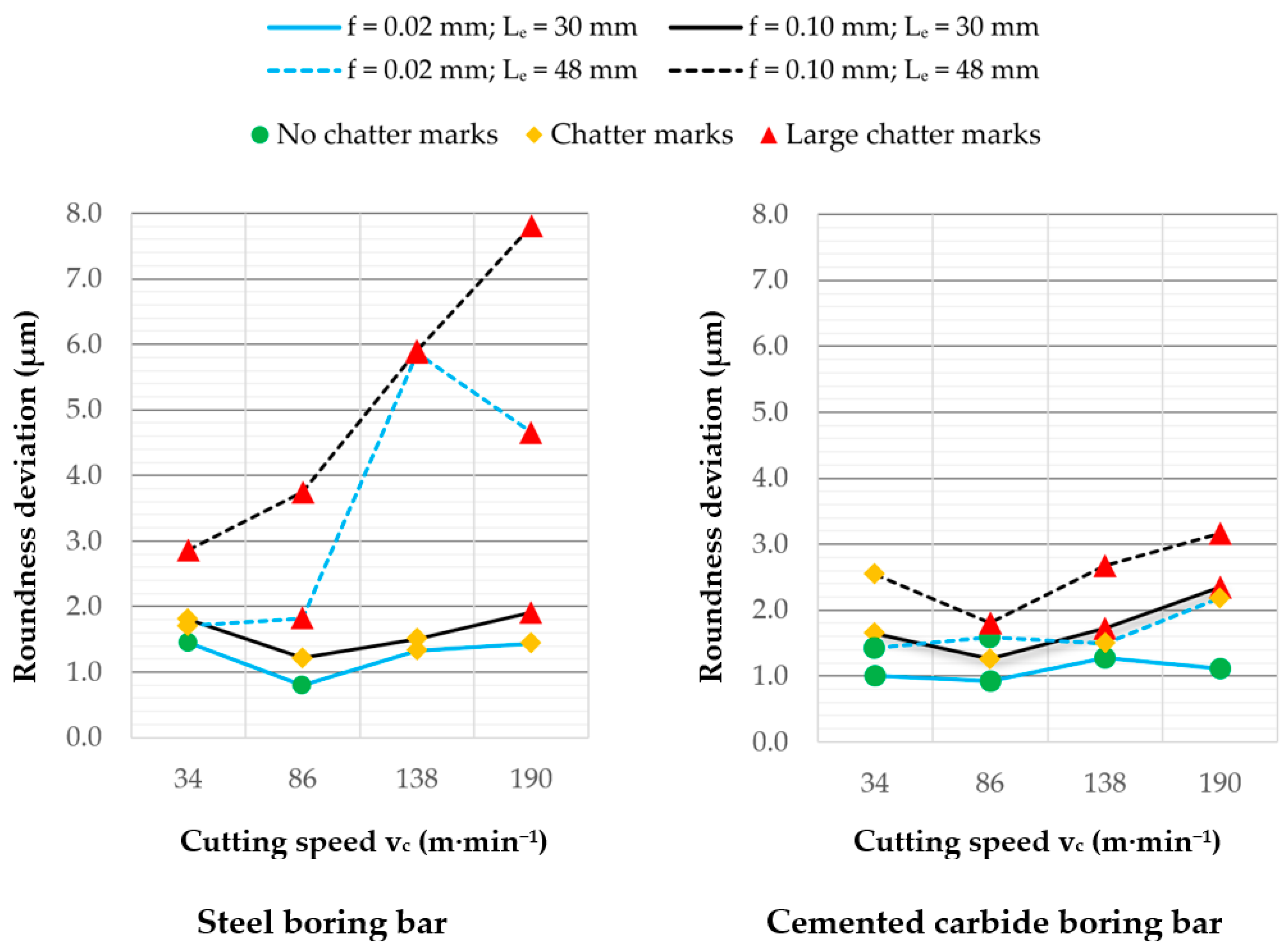
3.2. Roundness
4. Conclusions
Author Contributions
Funding
Data Availability Statement
Conflicts of Interest
References
- Kolesnyk, V.; Peterka, J.; Alekseev, O.; Neshta, A.; Xu, J.; Lysenko, B.; Sahul, M.; Martinovič, J.; Hrbal, J. Application of ANN for Analysis of Hole Accuracy and Drilling Temperature When Drilling CFRP/Ti Alloy Stacks. Materials 2022, 15, 1940. [Google Scholar] [CrossRef] [PubMed]
- Thomas, W.; Peterka, J.; Szabó, T.; Albuquerque, M.V.; Pederiva, R.; Kiss, L.P. Analytical and Experimental Investigation of the Dynamic Stability in Passive Damper Boring Bars. Procedia CIRP 2023, 117, 187–192. [Google Scholar] [CrossRef]
- Lu, X.; Chen, F.; Altintas, Y. Magnetic Actuator for Active Damping of Boring Bars. CIRP Ann. 2014, 63, 369–372. [Google Scholar] [CrossRef]
- Venkata Rao, K.; Murthy, B.S.N.; Mohan Rao, N. Cutting Tool Condition Monitoring by Analyzing Surface Roughness, Work Piece Vibration and Volume of Metal Removed for AISI 1040 Steel in Boring. Measurement 2013, 46, 4075–4084. [Google Scholar] [CrossRef]
- Venkata Rao, K.; Murthy, B.S.N.; Mohan Rao, N. Prediction of Cutting Tool Wear, Surface Roughness and Vibration of Work Piece in Boring of AISI 316 Steel with Artificial Neural Network. Measurement 2014, 51, 63–70. [Google Scholar] [CrossRef]
- Oborskyi, G.; Orgiyan, A.; Ivanov, V.; Balaniuk, A.; Pavlenko, I.; Trojanowska, J. Improvement of the Dynamic Quality of Cantilever Boring Bars for Fine Boring. Machines 2022, 11, 7. [Google Scholar] [CrossRef]
- Kaliński, K.J.; Galewski, M.A.; Mazur, M.R.; Stawicka-Morawska, N. An Improved Method of Minimizing Tool Vibration during Boring Holes in Large-Size Structures. Materials 2021, 14, 4491. [Google Scholar] [CrossRef]
- Ma, J.; Xu, J.; Li, L.; Liu, X.; Gao, M. Analysis of Cutting Stability of a Composite Variable-Section Boring Bar with a Large Length-to-Diameter Ratio Considering Internal Damping. Materials 2022, 15, 5465. [Google Scholar] [CrossRef]
- Moradian, H.; Abbasi, M.H.; Moradi, H. Adaptive Sliding Mode Control of Regenerative Chatter and Stability Improvement in Boring Manufacturing Process with Model Uncertainties. Proc. Inst. Mech. Eng. Part C J. Mech. Eng. Sci. 2020, 234, 1171–1181. [Google Scholar] [CrossRef]
- Jirapattarasilp, K.; Kuptanawin, C. Effect of Turning Parameters on Roundness and Hardness of Stainless Steel: SUS 303. AASRI Procedia 2012, 3, 160–165. [Google Scholar] [CrossRef]
- Matsubara, A.; Maeda, M.; Yamaji, I. Vibration Suppression of Boring Bar by Piezoelectric Actuators and LR Circuit. CIRP Ann. 2014, 63, 373–376. [Google Scholar] [CrossRef]
- Fu, Q.; Lundin, D.; Nicolescu, C.M. Anti-Vibration Engineering in Internal Turning Using a Carbon Nanocomposite Damping Coating Produced by PECVD Process. J. Mater. Eng. Perform. 2014, 23, 506–517. [Google Scholar] [CrossRef]
- Hayati, S.; Shahrokhi, M.; Hedayati, A. Development of a Frictionally Damped Boring Bar for Chatter Suppression in Boring Process. Int. J. Adv. Manuf. Technol. 2021, 113, 2761–2778. [Google Scholar] [CrossRef]
- Chockalingam, S.; Natarajan, U.; George Cyril, A. Damping Investigation in Boring Bar Using Hybrid Copper-Zinc Particles. J. Vib. Control 2015, 23, 2128–2134. [Google Scholar] [CrossRef]
- Hendrowati, W.; Merdekawan, N. Modeling and Analysis of Boring Bar Vibration Response in Internal Turning Due to Variation of the amount of DVA Rubber in Finish Boring Cut. J. Mech. Sci. Technol. 2021, 35, 4353–4362. [Google Scholar] [CrossRef]
- Bansal, A.; Law, M. A Receptance Coupling Approach to Optimally Tune and Place Absorbers on Boring Bars for Chatter Suppression. Procedia CIRP 2018, 77, 167–170. [Google Scholar] [CrossRef]
- Chen, F.; Hanifzadegan, M.; Altintas, Y.; Lu, X. Active Damping of Boring Bar Vibration with a Magnetic Actuator. IEEE/ASME Trans. Mechatron. 2015, 20, 2783–2794. [Google Scholar] [CrossRef]
- Yuhuan, Z.; Yongsheng, R.; Jishuang, T.; Jingmin, M. Chatter Stability of the Constrained Layer Damping Composite Boring Bar in Cutting Process. J. Vib. Control 2019, 25, 2204–2214. [Google Scholar] [CrossRef]
- Liu, X.; Liu, Q.; Wu, S.; Liu, L.; Gao, H. Research on the Performance of Damping Boring Bar with a Variable Stiffness Dynamic Vibration Absorber. Int. J. Adv. Manuf. Technol. 2017, 89, 2893–2906. [Google Scholar] [CrossRef]
- Hintze, W.; Hinrichs, M.; Rosenthal, O.; Schleinkofer, U.; Venturini, R. Model Based Design of Tuned Mass Dampers for Boring Bars of Small Diameter. Procedia CIRP 2023, 117, 193–198. [Google Scholar] [CrossRef]
- Thomas, W.; Diniz, A.E.; Pederiva, R.; Suyama, D.I.; De Albuquerque, M.V. A New Type Of Impact Damper with Long Overhangs in the Internal Turning of Hardened Materials. Procedia CIRP 2019, 82, 255–260. [Google Scholar] [CrossRef]
- Singh, G.; Mann, G.S.; Pradhan, S. Improving the Surface Roughness and Flank Wear of the Boring Process Using Particle Damped Boring Bars. Mater. Today Proc. 2018, 5, 28186–28194. [Google Scholar] [CrossRef]
- Ghongade, H.P. Investigation of Vibration in Boring Operation to Improve Machining Process to Get Required Surface Finish. Mater. Today Proc. 2022, 62, 5392–5395. [Google Scholar] [CrossRef]
- Sarode, K.; Nehe, P.; Deshpande, M. Chatter Mitigation in Boring Machining Process. Int. J. 2020, 5, 27–34. [Google Scholar]
- Sortino, M.; Totis, G.; Prosperi, F. Modeling the Dynamic Properties of Conventional and High-Damping Boring Bars. Mech. Syst. Signal Process. 2013, 34, 340–352. [Google Scholar] [CrossRef]
- Sandvik Coromant. Modern Metal Cutting: A Practical Handbook; Sandvik Coromant: Sandviken, Sweden, 1994; 960p, ISBN 9197229903. [Google Scholar]
- Sandvik Coromant. Metalcutting Technical Guide: Turning, Milling, Drilling, Boring, Toolholding; Handbook from Sandvik Coromant; Sandvik Coromant: Sandviken, Sweden, 2005; 617p. [Google Scholar]
- Sayeed Ahmed, G.M.; Quadri, S.S.H.; Mohiuddin, M.S. Optimization of Feed and Radial Force in Turning Process by Using Taguchi Design Approach. Mater. Today Proc. 2015, 2, 3277–3285. [Google Scholar] [CrossRef]
- Janáč, A.; Lipa, Z.; Peterka, J. Teória Obrábania (Theory of Machining); STU in Bratislava: Bratislava, Slovakia, 2006; ISBN 80-227-2347-9. [Google Scholar]
- Saravanamurugan, S.; Shyam Sundar, B.; Sibi Pranav, R.; Shanmugasundaram, A. Optimization of Cutting Tool Geometry and Machining Parameters in Turning Process. Mater. Today Proc. 2021, 38, 3351–3357. [Google Scholar] [CrossRef]
- Quintana, G.; Ciurana, J. Chatter in Machining Processes: A Review. Int. J. Mach. Tools Manuf. 2011, 51, 363–376. [Google Scholar] [CrossRef]
- Aldaş, K.; Özkul, I.; Eskil, M. Prediction of Surface Roughness in Longitudinal Turning Process by a Genetic Learning Algorithm. Mater. Mater. Test. 2014, 56, 375–380. [Google Scholar] [CrossRef]
- Zheng, G.; Xu, R.; Cheng, X.; Zhao, G.; Li, L.; Zhao, J. Effect of Cutting Parameters on Wear Behavior of Coated Tool and Surface Roughness in High-Speed Turning of 300 M. Measurement 2018, 125, 99–108. [Google Scholar] [CrossRef]
- Korkut, I.; Donertas, M.A. The Influence of Feed Rate and Cutting Speed on the Cutting Forces, Surface Roughness and Tool–Chip Contact Length during Face Milling. Mater. Des. 2007, 28, 308–312. [Google Scholar] [CrossRef]
- Wang, G.; Liu, Z.; Huang, W.; Wang, B.; Niu, J. Influence of Cutting Parameters on Surface Roughness and Strain Hardening during Milling NiTi Shape Memory Alloy. Int. J. Adv. Manuf. Technol. 2019, 102, 2211–2221. [Google Scholar] [CrossRef]
- Brown, I.; Schoop, J. The Effect of Cutting Edge Geometry, Nose Radius and Feed on Surface Integrity in Finish Turning of Ti-6Al4V. Procedia CIRP 2020, 87, 142–147. [Google Scholar] [CrossRef]
- Petropoulos, P.G. The Effect of Feed Rate and of Tool Nose Radius on the Roughness of Oblique Finish Turned Surfaces. Wear 1973, 23, 299–310. [Google Scholar] [CrossRef]
- Shah, D.; Bhavsar, S. Effect of Tool Nose Radius and Machining Parameters on Cutting Force, Cutting Temperature and Surface Roughness—An Experimental Study of Ti-6Al-4V (ELI). Mater. Today Proc. 2020, 22, 1977–1986. [Google Scholar] [CrossRef]


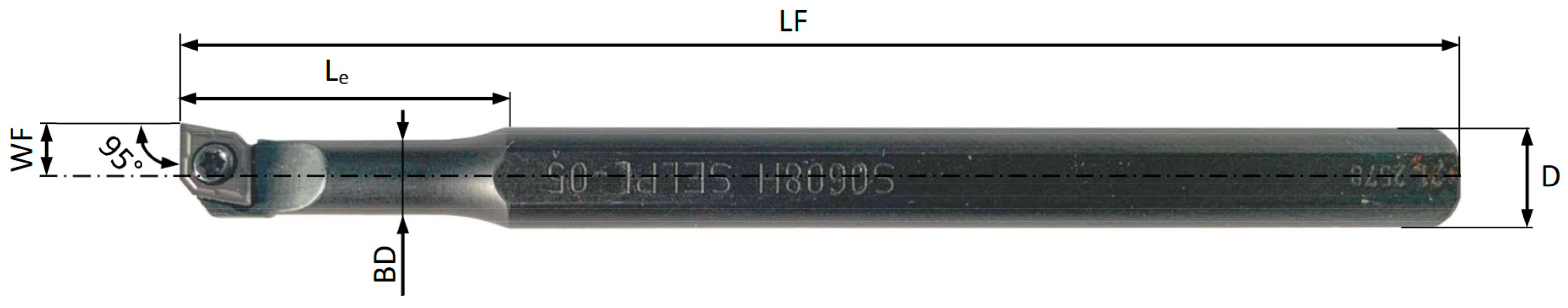
| Boring Bar | D (mm) | BD (mm) | WF (mm) | LF (mm) | Material |
|---|---|---|---|---|---|
| S 0608 H SELPL-05 | 8 | 6 | 4.5 | 100 | Steel |
| E 0608 H SELPL-05 | 8 | 6 | 4.5 | 100 | Cemented carbide |
| Cutting Parameter | Level 1 | Level 2 | Level 3 | Level 4 |
|---|---|---|---|---|
| Cutting speed vc (m·min−1) (spindle speed (min−1)) | 34 (888) | 86 (2245) | 138 (3602) | 190 (4960) |
| Feed f (mm) | 0.02 | 0.10 | ||
| Tool overhang length Le (mm) | 30 | 48 | ||
| Depth of cut ap (mm) | 0.10 |
| Recommended Cut-Off (ISO 4288-1996) | |||
|---|---|---|---|
| Non-Periodic Profiles | Cut-Off | Sampling Length/Evaluation Length | |
| Rz (µm) | Ra (µm) | λc (mm) | λc (mm)/L |
| >0.5–10 | >0.1–2 | 0.8 | 0.8/4 |
| Number of samples | 32 |
| Number of points measured around the circumference | 3600 |
| Number of cuts | 9 |
| Distance between cuts | 1 mm |
| Measuring speed | 3 min−1 |
| Evaluation method | MZC |
| Filtering method | GAUS 50 UPR |
Disclaimer/Publisher’s Note: The statements, opinions and data contained in all publications are solely those of the individual author(s) and contributor(s) and not of MDPI and/or the editor(s). MDPI and/or the editor(s) disclaim responsibility for any injury to people or property resulting from any ideas, methods, instructions or products referred to in the content. |
© 2024 by the authors. Licensee MDPI, Basel, Switzerland. This article is an open access article distributed under the terms and conditions of the Creative Commons Attribution (CC BY) license (https://creativecommons.org/licenses/by/4.0/).
Share and Cite
Vopát, T.; Kuruc, M.; Pätoprstý, B.; Vozár, M.; Jurina, F.; Bočáková, B.; Peterka, J.; Görög, A.; Straka, R. The Selection of Cutting Speed to Prevent Deterioration of the Surface in Internal Turning of C45 Steel by Small-Diameter Boring Bars. Machines 2024, 12, 68. https://doi.org/10.3390/machines12010068
Vopát T, Kuruc M, Pätoprstý B, Vozár M, Jurina F, Bočáková B, Peterka J, Görög A, Straka R. The Selection of Cutting Speed to Prevent Deterioration of the Surface in Internal Turning of C45 Steel by Small-Diameter Boring Bars. Machines. 2024; 12(1):68. https://doi.org/10.3390/machines12010068
Chicago/Turabian StyleVopát, Tomáš, Marcel Kuruc, Boris Pätoprstý, Marek Vozár, František Jurina, Barbora Bočáková, Jozef Peterka, Augustín Görög, and Róbert Straka. 2024. "The Selection of Cutting Speed to Prevent Deterioration of the Surface in Internal Turning of C45 Steel by Small-Diameter Boring Bars" Machines 12, no. 1: 68. https://doi.org/10.3390/machines12010068
APA StyleVopát, T., Kuruc, M., Pätoprstý, B., Vozár, M., Jurina, F., Bočáková, B., Peterka, J., Görög, A., & Straka, R. (2024). The Selection of Cutting Speed to Prevent Deterioration of the Surface in Internal Turning of C45 Steel by Small-Diameter Boring Bars. Machines, 12(1), 68. https://doi.org/10.3390/machines12010068