Article

Active Disturbance Rejection Control for Distributed Energy Resources in Microgrids

1
Lorraine Research Laboratory in Computer Science and Its Applications (LORIA, UMR CNRS 7503), Université de Lorraine, 54506 Nancy, France
2
LABISEN, ISEN Yncrea Ouest, Nantes Campus, 44470 Carquefou, France
3
Research and Higher Education Department, ICAM School of Engineering, Toulouse Campus, 31076 Toulouse, France
4
Laboratoire d’Informatique & Systèmes (LIS UMR CNRS 7020), Aix Marseille University, 13397 Marseille, France
5
Institut de Recherche Dupuy de Lôme (IRDL UMR CNRS 6027), University of Brest, 29238 Brest, France
*
Author to whom correspondence should be addressed.
Machines 2024, 12(1), 67; https://doi.org/10.3390/machines12010067
Submission received: 16 September 2023 / Revised: 30 December 2023 / Accepted: 12 January 2024 / Published: 16 January 2024
(This article belongs to the Section Automation and Control Systems)

Abstract

:
Motivated by the significant efforts developed by researchers and engineers to improve the economic and technical performance of microgrids (MGs), this paper proposes an Active Disturbance Rejection Control (ADRC) for Distributed Energy Resources (DER) in microgrids. This approach is a nonlinear control that is based on a real-time compensation of different estimated disturbances. The DER operates along with the electrical grid to provide the load requirements. This load has a nonlinear and uncertain character, which presents a source of unmodeled dynamics and harmonic perturbations of the MG. The main objective of this paper is to ensure the stability and the continuity of service of the distributed generation resources by controlling the DC-AC converter. The ADRC as a robust control technique is characterized by its ability to compensate for the estimated total disturbances caused by the load variation and the external unmodeled perturbations to guarantee the high tracking performance of sinusoidal reference signals in the DER system. The ADRC technique is characterized by its nonlinear function, which provides a high robustness to the controlled system. However, in order to simplify the control structure by keeping its high reliability, this paper proposes to replace the nonlinear function with a simple error (termed linear ADRC), compares the impact of this modification on the system performances, and evaluates its operation in the presence of linear and nonlinear load variations. Simulation results are presented to demonstrate the efficiency of the proposed control approach for a three-phase DER.

1. Introduction

The microgrid is not a new concept, but its importance increases every day because of the world’s demand for green energy and secure and clean electricity. Nowadays, the definition of microgrid is changing to provide more choices in terms of grid flexibility, reliability, and economy with high penetration of renewable energy resources, energy storage devices, and controllable loads. A most concise definition is given by the Microgrid Exchange Group (MEG) [1]: “A microgrid is a group of loads and distributed energy resources interconnected within clearly defined electrical limits that acts as a single entity controllable in relation to the grid. A micro-network can connect and disconnect from the network to allow it to operate in both isolated and connected mode”. A microgrid, as an energy system, consists of a variety of components, including [2,3] distributed energy resources (DER), distributed energy storage devices (DES) that can be used to absorb excess power and discharge to cover the power deficit during on-peak periods, controller units, and controllable and non-controllable loads. The characteristics and dynamics of each component of the microgrid present a major challenge in terms of control and operation in both grid-connected and islanded modes. Given the importance of this concept for the construction of a sustainable electrical system, many innovative techniques and approaches have been proposed around the world to control the DER in microgrids to improve its performance and enhance its resilience.
Starting with the modeling, authors in [4] improve the balance between the dynamic model precision and the steady state of the DER’s converter by modifying the control reference to simplify its integration into the control algorithm. After modelling the MG, authors in [5] rely on multi-loop control for the voltage optimal control strategy. This technique comprises a predictive current controller, which enhances the performance of power converters in the MG. Combining the voltage regulator’s operation and the inverter capability improves the expected results of the controlled system [6]. In [7], the authors propose the elimination of the load disturbance with the deadbeat control strategy. Even though this technique provides great results in the case of instantaneous perturbations, it loses its robustness, as it is sensitive to periodic perturbations. Furthermore, a repetitive regulator is suggested for the single-loop current control in [8]. This technique can improve the system’s stability and steady-state performance in practice by the disturbance suppression, but presents a period delay in the dynamic response process. Other researchers, as presented in [9], choose to use the traditional PI regulators to control the DER system. Despite the simplicity of the structure of this kind of regulator, it is sensitive to system modeling errors, parameter uncertainties, and external disturbances, which can cause some undesired system performance and loss of stability. To deal with these issues, authors in [10] introduced a resonant controller based on the addition of harmonic modes in the direct control loop. This method presents significant results in ideal cases, but the increase in the controller’s number simultaneously used to improve the process performance may complicate the controller parameter tuning.
Inverters in DER are a major source of harmonic distortions and high total harmonic distortion (THD), which are mitigated using LC or LCL filter-based electronic circuits or through active power filters. These harmonics threaten the DER performance, stability, and may cause some power quality issues at load side [2,11]. Additionally, the presence of periodic disturbances caused by linear and nonlinear loads, DER parameter variation, and system uncertainties decrease the tracking ability of the reference voltage signal and threaten the system’s accuracy and reliability [12]. Consequently, in order for DER to operate in optimal and nominal conditions with high performance and low harmonic distortion, an adequate and robust control strategy is required [13,14].
To implement a control approach for DER, a model is required. The use of the accurate and simple mathematical model to design a controller is of paramount importance. Usually, an accurate mathematical model is not necessarily the best one for control law derivation. The more the model is detailed, the lower the simulation speed becomes [15]. Usually, distributed energy resource models are presented in the synchronous reference frame ( d q 0 ) or the stationary reference frame ( α β ) . Moreover, In the literature, several mathematical modeling approaches of DER units have been presented. In [16], the authors proposed a mathematical modeling of distributed energy resources using a Generalized Average Model. In [17], the authors proposed State-Space Averaging Modeling and small-signal modeling by discussing their advantages and limitations. Furthermore, multivariable closed-loop modeling is proposed in [18]. An Impedance Modeling method in the synchronous d q reference frame for inverters is proposed in [19]. A harmonic-linearization-based sequence impedance model is proposed in [20]. Both models allow addressing the harmonic instability and low-frequency oscillation problems.
Based on modern control theory, an Active Disturbance Rejection Control (ADRC) was introduced by Han Jingqing [21]. This approach has the advantages of a versatile and simple structure design, independence from exact process mathematical model, and high stability and immunity from the internal and the external perturbations. The ADRC has proved its efficiency in many engineering applications and several harsh operating conditions [22,23,24]. This technique has the capability to actively compensate for the estimated perturbations from the system’s measured input and output parameters and reduce its effects on the process performances. The core of this approach is the extended state observer (ESO), which is able to estimate in real time both the internal states and the total disturbances (internal and external disturbances with nonlinear terms and uncertainties). Then, the estimated perturbation is compensated for at the same time using the Non-Linear State Error Feedback (NLSEF), also called the control law.
ADRC, as a robust control strategy, is introduced in this work. This control approach is mainly based on grouping all disturbances, undefined quantities, model uncertainties, and nonlinear terms into a single parameter called “the total disturbance”, which is estimated and then used as feedback control action to reject its influence on system performance. The effectiveness of this technique is reflected by the stability and large controllable range provided to the system even for an approximate mathematical model, in addition to the real-time estimation and compensation ability. Unfortunately, the nonlinear function used in the ADRC and the numerous parameters to be adjusted may complicate its implementation and lower the simulation speed. In this context, and after proving the efficiency of the proposed technique, a modification is proposed to simplify the controller structure by replacing the nonlinear function with a simple error, as introduced in [25]. Indeed, the linearization of the ADRC has been proven to simplify the control loop structure and implementation in different application areas [26,27].
The main contributions of this paper are twofold:
  • A thorough and consistent theoretical study and stability analysis of an ADRC-based controller for DER disturbance rejection in microgrid application.
  • In-depth simulation analysis of the proposed ADRC-based controllers (both linear and nonlinear ADRC) for DER under several conditions: linear and nonlinear loads and parameter uncertainties.
The proposed robust control technique is based on online estimation and compensation of both the state-space parameters and external disturbances caused by the load variations in order to ensure the stability and the continuity of the DER system to provide an output sinusoidal signal equivalent in its characteristics to main grid voltage. Owing to its ability to improve the disturbance rejection using the online compensation of estimated total perturbation, which affects the system stability, the ADRC technique is introduced to control the DER system by minimizing the steady-state error and increase the rejection capability of multiple harmonics caused by the nonlinear loads.
The remaining parts of this manuscript are organized as follows. Section 2 presents the DER mathematical modelling. Section 3 introduces the ADRC approach with the stability analysis used to control the DER DC-AC converter. Section 4 applies the ADRC to implement the cascaded control loops of the output current and voltage of the DER. Section 5 provides some simulation results considering DER parameter variation and nonlinear load influence. Finally, Section 6 concludes this paper and provides some directions for future works.

2. Microgrid: DER System Modelling

Nowadays, microgrids generate power using sustainable renewable energy resources (RES, i.e., hydropower, wind, PV, geothermal, etc.). However, due to their fluctuating nature, these renewable sources cannot be used at any given time to meet fluctuating energy demands, as they may disrupt the grid’s daily operation planning. These renewable resources are considered as non-dispatchable sources. To avoid this issue, they are integrated with other components in distributed energy resource units to form a controllable renewable energy source connected to nearby consumers to allow production consumption balance.

2.1. System Description

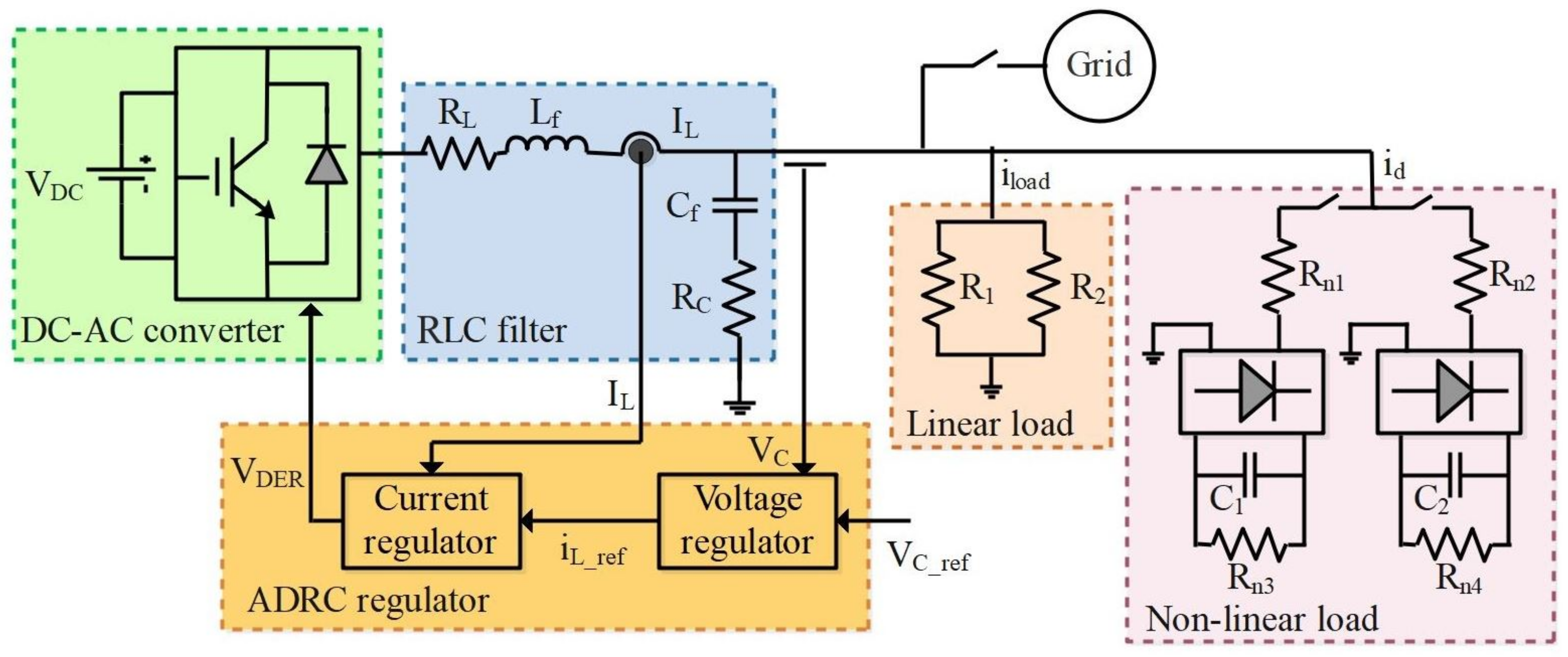
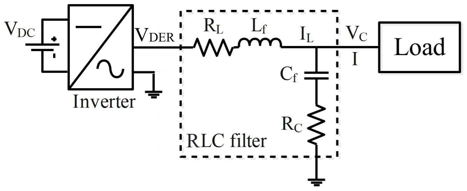
The general scheme of the considered voltage inverter is shown in Figure 1. It is composed of three main elements, which include the DC bus source, the three-phase inverter, and an RLC filter that is connected to the load and main grid. L f , R L , C f , and R C are filter parameters, including inductance, resistance of inverter-side inductor, filter capacitance, and resistance of capacitor, respectively.
The DER model, presented in this work, is that of a three-phase model, but for simplicity reasons, only the first phase was described in the different diagrams and the mathematical model.
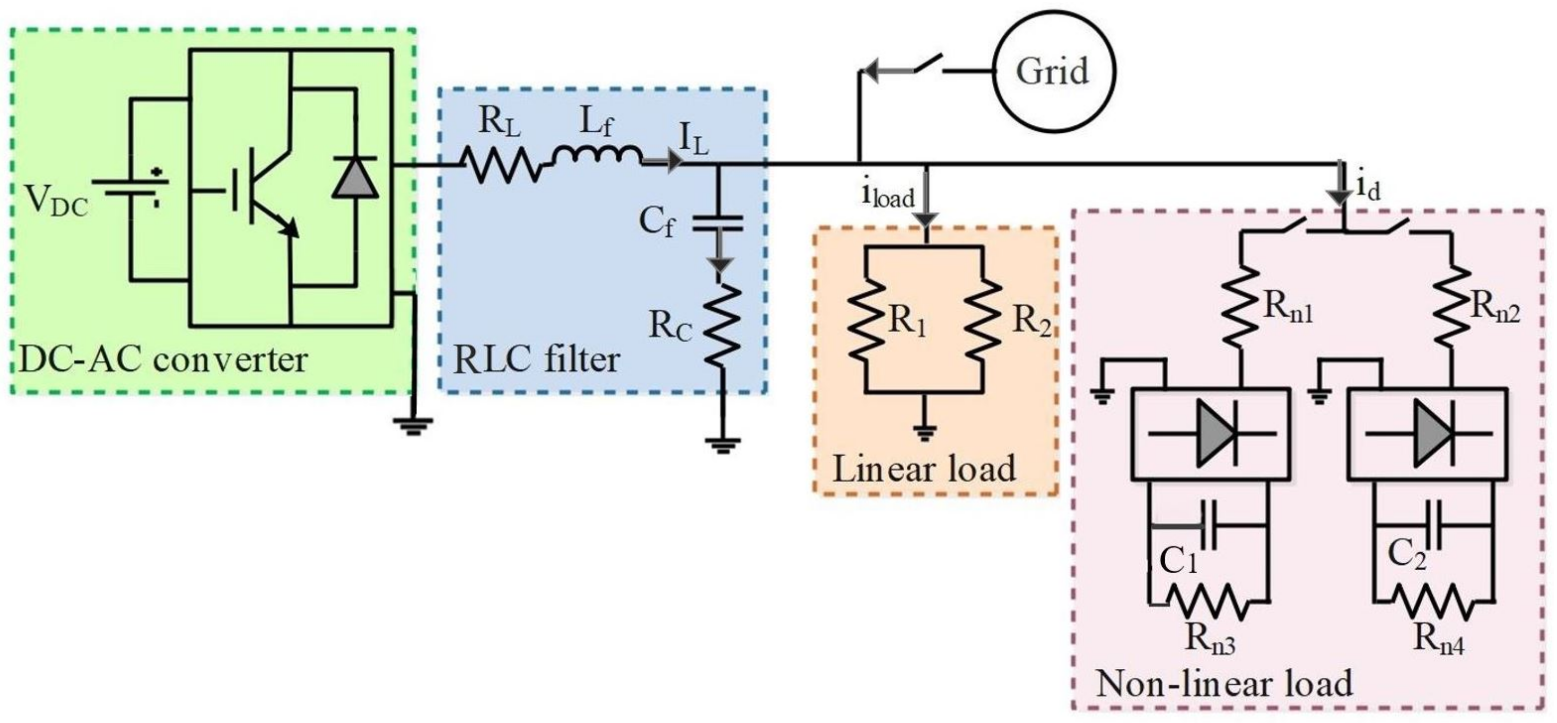
The inverter output voltage, V D E R , is synthesized using Pulse Width Modulation (PWM), while the RLC filter is added as a low-pass filter to reduce the switching harmonics, as detailed in Figure 2. The DC bus is the common DC bus of the distributed energy resources that is usually controlled to a constant value using the energy storage devices or the main grid.
To model the behavior of the DER in dynamic mode, it is necessary to establish the relationship between voltages and currents of this system. In the proposed DER mathematical model, the power electronic converter’s DC link voltage is assumed to be constant. Indeed, it is controlled by primary renewable energy sources or energy storage devices (i.e., in islanded mode when using a wind turbine as RES, which implements the MPPT algorithm, the DC bus voltage is controlled by the DC-DC converter associated to the energy storage system).

2.2. Mathematical Model of DER

Based on Kirchhoff’s current law, the relation between the currents flowing through the RLC filter can be described by:
i L = i C + i d + i l o a d
where i C corresponds to the capacitor current, i l o a d is the current flowing through the linear load, and i d is defined as a set of the different currents that can affect the system during operation, termed the disturbance current with unknown dynamic profile and depending on the applied load. Although it represents an input to the DER system, it is considered as a non-controllable quantity.
Using the Kirchhoff voltage law, the V D E R voltage can be expressed by:
V D E R = v l o a d + v L + v R L
with:
v l o a d = v R C + v C v R L = i L · R L v L = L f d i L d t i C = C f d v C d t
Based on the previously presented detailed scheme and using Equation (3), v l o a d can be expressed by:
v l o a d = v C + v R C = v C + i C R C = v C + C f R C d v C d t = Z l o a d i l o a d
Using the relations defined by Equations (3) and (4), the current i L flowing through the inductance of the RLC filter can be described as:
i L = C f d v C d t + v l o a d Y l o a d + i d
The load-equivalent impedance Z l o a d can be expressed as Z l o a d = 1 Y l o a d , with Y l o a d being the admittance. Z l o a d and Y l o a d are two time-varying and bounded parameters. Taking into account the unloaded and nominal operation conditions of the considered DER, Z l o a d can be defined as 5 Ω < Z l o a d < 10 4 Ω , which implies 0.0001 S < Y l o a d < 0.2 S .
Replacing Equation (4) in Equation (5), we obtain:
i L = C f d v C d t + Y l o a d ( v C + C f R C d v C d t ) + i d
Then, the derivative of v C can be deduced from Equation (6) as a function of the measured parameters. The first state equation defining the capacitor voltage can then be expressed as follows:
d v C d t = 1 C f + Y l o a d C f R C ( i L v C Y l o a d i d )
The second state equation related to the inductance current can be deduced from Equation (2) by using Equations (3) and (4). Indeed, V D E R can be rewritten as:
V D E R = L f d i L d t + C f R C d v c d t + i L R L + v C
Replacing Equation (7) in Equation (8), V D E R and the derivative of the inductive current d i L d t can be expressed as in Equations (9) and (10).
V D E R = v C + i L R L + L f d i L d t + C f R C 1 C f + Y l o a d C f R C ( i L v C Y l o a d i d )
d i L d t = 1 L f V D E R 1 L f ( R L + R C 1 + Y l o a d R C ) i L 1 L f ( 1 R C 1 + Y l o a d R C ) v C + 1 L f R C 1 + Y l o a d R C i d
In order to simplify the mathematical modelling of the DER, the resistance R C used in the RLC filter can be neglected. Then, the state-space equations can be rewritten as follows:
d v C d t = 1 C f i L Y l o a d C f v C 1 C f i d
d i L d t = 1 L f V D E R R L L f i L 1 L f v C
Finally, the state-space representation for the DER system can be given by:
x ˙ ( t ) = A x ( t ) + B u ( t ) + D d ( t ) y ( t ) = C x ( t )
with A = R L L f 1 L f 1 C f Y l o a d C f , B = 1 L f 0 , D = 0 1 C f and C = 0 1 , where the state vector x ( t ) = i L v C T , the input and the output parameters are, respectively, V D E R and v C , and d = i d is the unknown input variable or the external disturbance of the DER system.
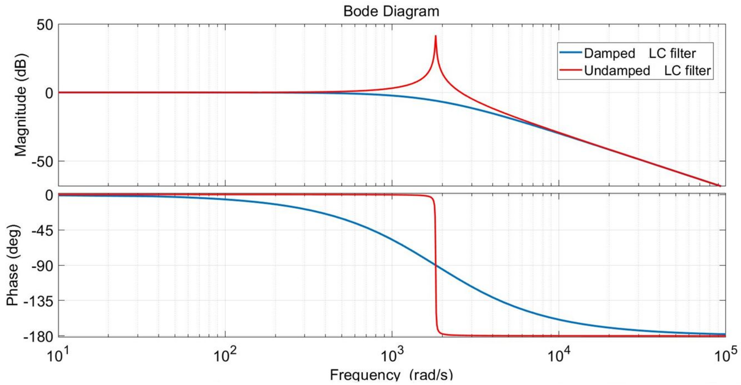
Based on the previous mathematical developments, the Bode diagram of the RLC filter used in the microgrid in the inverter side is shown in Figure 3, with a resonance peak at the resonance frequency. Therefore, an active damping method is recommended, instead of the passive method, which increases the power losses and reduces efficiency. Moreover, the DER’s characteristics are sensitive to variations due to different operating conditions. Because of the disturbances caused by the system parameter uncertainties and the external disturbances, an accurate system description will be very difficult to define, which makes it difficult to control. However, the interesting features of the nonlinear ADRC and its ability to mitigate system parameter uncertainty and the disturbances affecting the process may improve the control’s robustness, precision, and performance with the minimum information about the system’s dynamics. Hence, the purpose of the next section is to compute the controllers in order to control the output voltage to a desired reference and to ensure the system’s closed-loop stability with the desired performance, while minimizing the effect of disturbances, measurement noises, and avoiding the impact of modelling uncertainties, parameter variations, and harmonic perturbations caused by the nonlinear loads.

3. Active Disturbance Rejection Control

With the increase in DER in microgrids, many control techniques have been developed. However, most of these approaches require the knowledge of detailed DER models and accurate parameter values. Moreover, disturbances, uncertainty, and unknown dynamics of nonlinear loads are not considered in most of those controllers’ designs. To overcome these drawbacks, an Active Disturbance Rejection Control (ADRC) approach is proposed to control the DER output voltage with the objective to improve the disturbance rejection efficiency and achieve faster convergence capability.

3.1. ADRC Structure

Assuming that an exact mathematical model is not available because of external disturbances caused by linear and nonlinear loads, the process dynamic model in the state-space can be expressed as follows [21]:
x ˙ ( t ) = a · x ( t ) + b · u ( t ) + d ( t ) + Δ y ( t ) = C x ( t )
where x is the state-space variable vector, u is the input variable, a is a known parameter, d is the unknown external disturbances, and Δ stands for state model uncertainty. Furthermore, b = b 0 + Δ b , where b 0 is the approximate value of b and Δ b is the uncertainty. Since the uncertainty can affect the controlled state variables (matrix a), the term a x ( t ) + Δ b can be defined as the unknown dynamics of the system [28]. To simplify this expression, global disturbances, the nonlinear terms, and the unknown dynamics can be denoted as f. Then, using the ADRC framework, Equation (14) becomes:
x ˙ ( t ) = a · x ( t ) + b 0 · u ( t ) + Δ b · u ( t ) + d ( t ) = b 0 · u ( t ) + f ( x , t , d ) y ^ ( t ) = C x ( t )
Since f ( t ) is unknown, the ADRC technique presents a great interest to control this kind of process with a real-time estimation and compensation of state-space variables and global disturbances using only the known input u ( t ) and the measured output y ( t ) by an extended state observer (ESO). Then, a nonlinear control law is implemented to control the output. To achieve this, f ( t ) must be defined as an unknown and differentiable parameter with a bounded derivative h = f ˙ [29].
Based on the ADRC’s structure presented in Figure 4, the Tracking-Differentiator (TD) is the part in the control scheme that arranges the transition process using the generalized derivative of the reference input signal, z 1 and z 2 are the estimation of the internal and extended state variables, and b 0 is the approximated estimation of b.
The first-order TD structure is defined by:
ε 0 = v 1 v v 1 ˙ = r f a l ( ε 0 , α 0 , δ 0 )
where r is the tracking speed factor, and v = y r e f and v 1 are the reference input and the output signal after TD arrangement, respectively.
The ESO can be expressed in the form of:
ε 1 = z 1 y z 1 ˙ = z 2 + b 0 u ρ 1 f a l ( ε 1 , α 1 , δ 1 ) z 2 ˙ = ρ 2 f a l ( ε 1 , α 1 , δ 1 )
where ρ 1 and ρ 2 are the observer gains.
Then, the nonlinear control law, or the NLSEF, is given by:
e = v 1 y = v 1 z 1 u 0 = ρ 3 f a l ( e , α 2 , δ 2 ) u = u 0 z 2 b 0
Parameter z 2 is the estimation of f and b 0 is the estimation of b. Moreover, v 1 is the reference input, z 1 is the estimate value of y, and ρ 3 is the proportional controller gain. All gains ρ 1 , ρ 2 , and ρ 3 that define the ESO and the NLSEF depend mainly on the control system sampling time, as discussed in [30].
It is worth noting that the ADRC approach implementation is based upon the nonlinear function f a l , which is the key of the controller design. In our case, the following nonlinear function has been considered:
f a l ( e , α , δ ) = e δ 1 α , e δ e α s i g n ( e ) , e > δ .
The conditions of derivability and continuity can be justified using this nonlinear function, where δ and α are the filter and the nonlinear factors, with:
0 < δ 0 < α < 1
Based on the approximated model of the RLC filter’s dynamic, the output signal y can be defined as the first state variable of the first-order reduced model, and the total disturbance f will be introduced as a second extended state variable. The ADRC, as a robust control technique, is configured to transform a complex system’s structure into a cascade integrator model to simplify its control and treat the rest of the quantities and signals as a global disturbance [31], which makes this approach a powerful tool for system control under model and parameter uncertainties and disturbances.
Assuming that the exact mathematical description of the system is unknown and with the presence of global disturbance, the authors in [32] have proposed to consider the process dynamic in Equation (14), which can be presented in the ADRC framework using the following augmented state-space form:
x 1 ˙ = x 2 + b u x 2 ˙ = h y = x 1 w h e r e h = f ˙
which implies:
x ˙ ( t ) = A x ( t ) + B u ( t ) + E h ( t ) y ( t ) = C x ( t )
with A = 0 1 0 0 , B = b 0 , E = 0 1 , and C = 1 0
The new ESO description, presented by Equation (17), can be expressed as follows:
z ˙ ( t ) = A z ( t ) + B 0 u ( t ) + L ( y ( t ) y ^ ( t ) ) = ( A L C ) z ( t ) + B 0 u ( t ) + L y ( t ) = A e z ( t ) + B 0 u ( t ) + L y ( t ) y ^ ( t ) = C z ( t )
where B 0 is the approximation matrix of B, and L denotes the new ESO gain vector given by:
L = ρ 1 ρ 2 = 2 ω 0 ω 0 2
where ω 0 is the ESO bandwidth.
Finally, the extended state variable, which is estimated by the ESO, is compensated for using the NLSEF presented by Equation (18). Consequently, the system dynamics can be defined by:
y ˙ = b . u + f = u 0 z 2 + f u 0
It can also be noted that:
y ˙ = ρ 3 ( v 1 y )
The transfer function of the closed-loop system is given by:
T y ( s ) = y ( s ) v 1 ( s ) = ρ 3 s + ρ 3

3.2. Performance Analysis of ADRC

As previously outlined, ESO is the core of the ADRC because of its ability to define an unknown function as an extended state variable, which is estimated and then compensated for using a nonlinear control law. Parameter tuning for both the ESO and NLSEF significantly affects the control performance, and thus the closed-loop system stability and the effectiveness of the ADRC [21]. Furthermore, due to the significant number of parameters to be set in the ADRC, the nonlinear function used in the different parts of the ADRC complicates the theoretical performance analysis of the regulator. In order to simplify the mathematical developments, the f a l function presented in Equations (17) and (18) can be replaced by a simple error, i.e., f a l = e , to be able to compute the transfer function of the observer [33]. Hence, using the Laplace transform on the ESO, the expressions z 1 and z 2 in the s-domain are given as follows:
z 1 = ρ 1 s + ρ 1 + ρ 3 y + ρ 3 s + ρ 1 + ρ 3 v 1
z 2 = ρ 2 ( s + ρ 3 ) s ( s + ρ 1 + ρ 3 ) y ρ 2 ρ 3 s ( s + ρ 1 + ρ 3 ) v 1
Then, the ADRC control law introduced by Equation (18) can be expressed as follows:
u ( s ) = T 1 ( s ) v 1 ( s ) T 2 ( s ) y ( s )
with
T 1 ( s ) = 1 b 0 ρ 3 ( s 2 + ρ 1 s + ρ 2 ) s ( s + ρ 1 + ρ 3 )
and
T 2 ( s ) = 1 b 0 ( ρ 3 ρ 1 + ρ 2 ) s + ρ 2 ρ 3 s ( s + ρ 1 + ρ 3 )
Finally, using both Equations (25) and (30), the output signal in the s-domain can be described by:
y ( s ) = 1 s ( b u ( s ) + f ( s ) ) = 1 s ( b ( T 1 ( s ) v 1 ( s ) T 2 ( s ) y ( s ) ) + f ( s ) ) = s ( s + ρ 1 + ρ 3 ) ( s + ρ 3 ) ( s 2 + ρ 1 s + ρ 2 ) f ( s ) + ρ 3 s + ρ 3 v 1 ( s ) = T 3 ( s ) f ( s ) + T y ( s ) v 1 ( s )
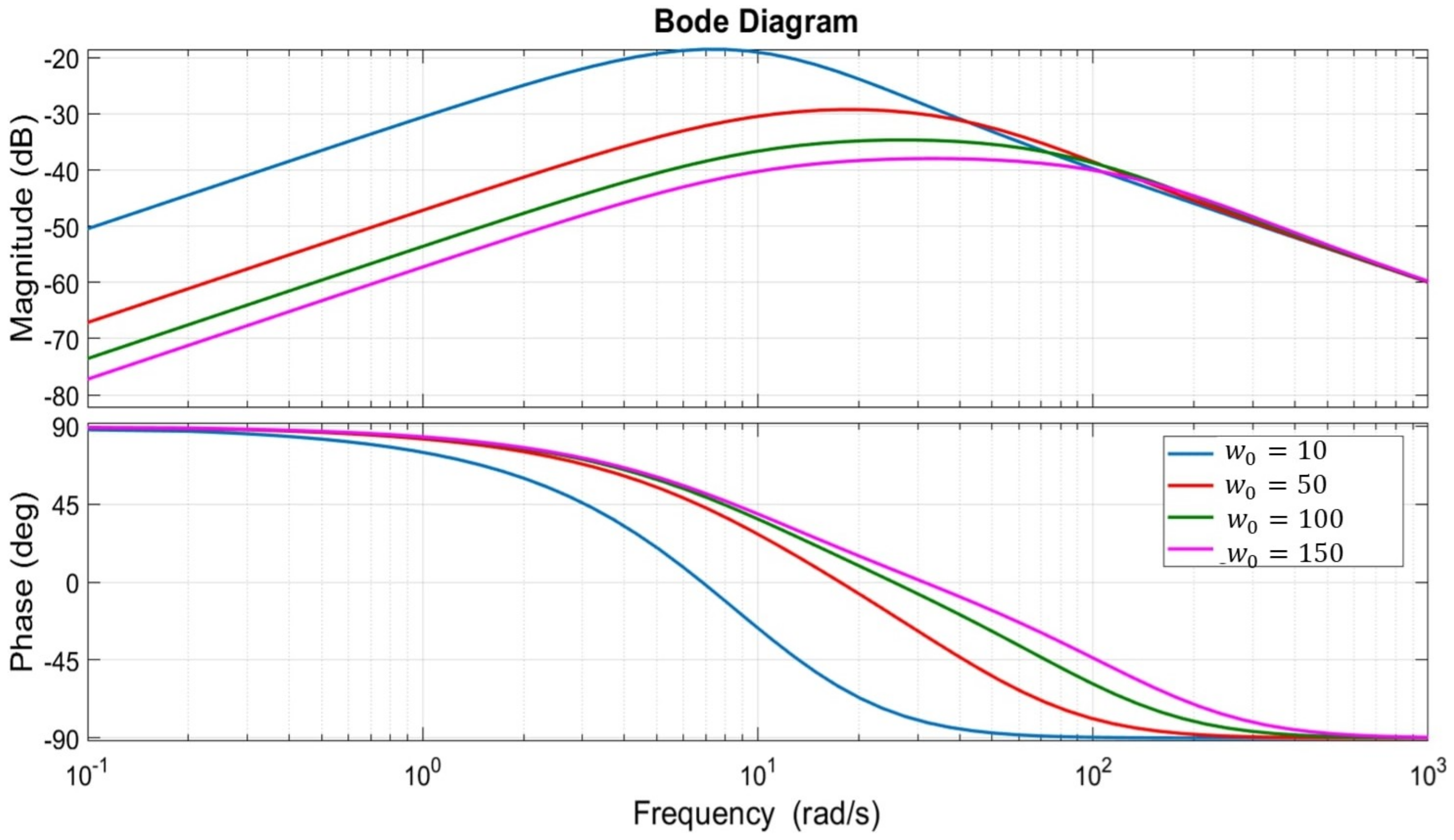
It can be noted that the output signal y is dependent on the desired reference signal and the total disturbance affecting the process. Assuming the disturbance term f is neglected, the transfer function of y can be equal to T y , and then the control output depends only on the control law gain ρ 3 . Figure 5 describes the impact of the variation in ρ 3 on the stability margin. By increasing the proportional controller gain, the high-pass filtering is enhanced as well as the tracking speed and the stability margin.
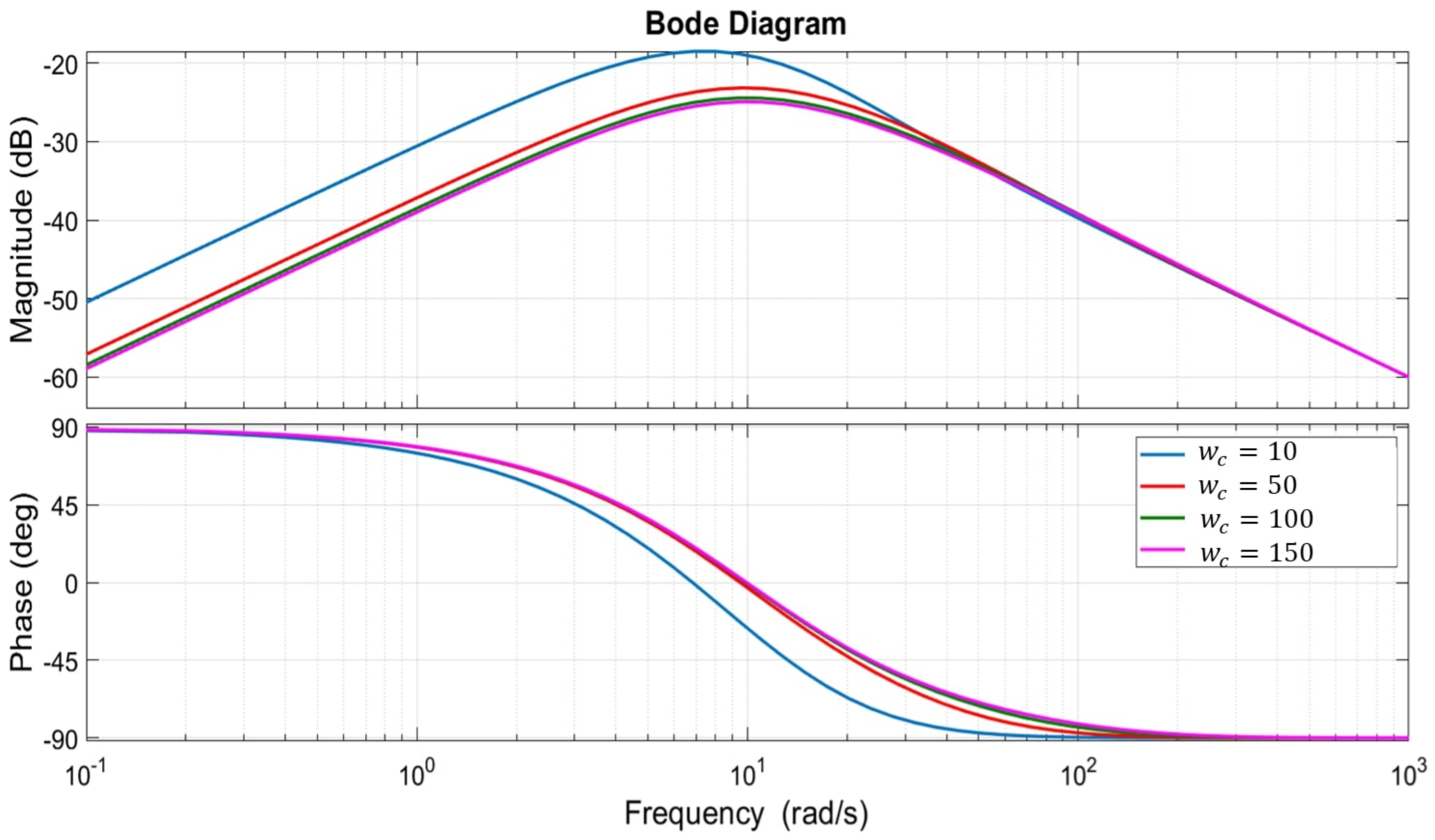
With consideration of the total disturbance term, it can be deduced from the control law description and the output signal presented, respectively, by Equations (30) and (33) that the closed-loop control’s stability depends mainly on the ESO and the NLSEF gains: ρ 1 , ρ 2 , and ρ 3 . Using the relation between the observer’s gains ρ 1 , ρ 2 and the observer bandwidth ω 0 described in Equation (24), the bode diagram of T 3 ( s ) is provided in Figure 6 and Figure 7. These figures describe the effect of changing the observer and the control law gains, where ω 0 is the observer bandwidth and ω c = ρ 3 is the control law bandwidth.
From these figures, it can be seen that the increase in ρ 1 , ρ 2 , or ρ 3 improves the disturbance rejection ability. It is noteworthy that the observer gains must be chosen in consideration of the speed of state estimation and the sensitivity over the noises and the disturbances [34]. Moreover, considering the use of two regulators in cascade, it is mandatory to consider that the inner loop is faster as compared to the outer loop while adjusting the observer and the control law parameters.

3.3. Stability Analysis

To achieve the best results in terms of stability, reliability, and robustness, the ADRC’s parameters can be deduced using the Lyapunov function, which is the most popular technique used for stability analysis, especially for a nonlinear regulator applied for uncertain systems, as described in [35]. The stability study is mainly used to validate the existence of appropriate gains in the ADRC that guarantee the convergence of the estimation errors.
Based on the generalized state-space description presented by Equation (23), we can define the tracking error e = x z and its dynamic as follows:
e ˙ = A e e + d
with A e = A L C = ρ 1 1 ρ 2 0 and d = E h .
Lemma 1.
It can be noted that the error e is bounded if h is bounded and the matrix A e is Hurwitz.
Proof. 
Assuming the matrix A e is Hurwitz, the Lyapunov function V and its solution X can be presented by:
V = e T X e
with
A e T X + X A e = P
and P is a positive definite matrix.
According to [36], the derivative of Equation (35) is given by:
V ˙ = e T P e + 2 d T X e = ( e T P 1 2 d T X P 1 2 ) ( e T P 1 2 d T X P 1 2 ) T + ( d T X P 1 2 ) ( d T X P 1 2 ) T
which implies that V ˙ < 0 if:
e T P 1 2 d T X P 1 2 2 > d T X P 1 2 2
then
2 d T X P 1 2 2 < e T P 1 2 2
For P = I , an identity matrix, V ˙ < 0 if:
e 2 > 2 X d 2
which implies that e 2 decreases for all e satisfying (40). Consequently, the error e is bounded. □

4. ADRC-Based Approach for Current and Voltage Control

The mathematical modeling of the DER unit is developed on a stationary reference frame ( α β ) . In this reference frame, sinusoidal quantities are used to design the controller, which is in accordance with the AC nature of the designed microgrid [37]. To meet the desired control dynamic performances, stability requirements, and robustness, ESO and NLSEF gain tuning for voltage and current regulators is not an easy task, especially for cascaded control loops. To deal with this issue, a detailed mathematical model is proposed in the following to simplify the controller design and performance analysis for different scenarios. This study eases the design of the power converter output voltage and current controllers and the analysis of all the harmonics and disturbances caused by different loads supplied by DER units.

4.1. Voltage and Current Controller Design

The first step for v c regulation is to reformulate its equation, presented in Equation (11) as follows:
d v C d t = 1 C f i L Y l o a d C f v C 1 C f i d = 1 C f i L + f 1 ( t ) = b 1 u ( t ) + f 1 ( t )
with b 1 = 1 C f , u ( t ) = i L and f 1 ( t ) = Y l o a d C f v C 1 C f i d .
To eliminate the steady-state error, the estimated disturbance using ESO must be compensated for as a feedforward signal for the NLSEF, as presented in Figure 4. Moreover, the estimated state-space is compared with the reference value to build the input of the TD block. Finally, the output signal of the voltage ADRC-based controller is the reference value of inductor current i L f , which is the input signal for the inner loop controller.
For the inner loop ADRC-based controller, the equation related to inductor current i L f dynamic is used, which is given by:
d i L d t = 1 L f V D E R R L L f i L 1 L f v C = 1 L f V D E R + f 2 ( t ) = b 2 u ( t ) + f 2 ( t )
with b 2 = 1 C f , u ( t ) = V D E R and f 2 ( t ) = R L L f i L 1 L f v C .

4.2. ADRC-Based Control General Structure

The regulator design for the DER control in the microgrid can be presented by the scheme provided in Figure 8. It consists of a voltage regulator that provides the current reference and inner loop current regulator that provides the modulation signals for the DC-AC converter. Figure 9 presents a detailed scheme of the structure of ADRC regulators used to control the DER in the microgrid. The output signal of the ADRC presents the V D E R , which is the input signal for the inverter (control signals for DER) that allows producing an output voltage wavefom equivalent to the main grid voltage in terms of amplitude, frequency, and waveform.

5. Simulation Results

The proposed controller is used for one distributed generator in order to improve voltage waveform, system stability, disturbance rejection (i.e., rejection capability to switch harmonics and harmonics caused by nonlinear loads), dynamic performances, and robustness under parameter uncertainty. Given the critical importance of the loads, international standards (ANSI/IEEE, 1986; IEC, 2011) [38,39] govern the performance of Distributed Energy Resources (DER), establishing criteria for both transient and steady-state operations. In transient conditions, adherence to standards necessitates minimal fluctuations in the output voltage amplitude and swift recovery times when loads are introduced or removed from the system. In the steady state, a DER’s output voltage must manifest as a sinusoidal signal with a consistent amplitude and frequency.
For the signal to be recognized as sinusoidal amidst periodic disruptions induced by nonlinear loads, compliance with prescribed limits for Total Harmonic Distortion (THD) outlined in these standards is mandatory. A fundamental performance expectation for a distributed energy resource (DER) system producing a sinusoidal output is the delivery of a voltage with minimal harmonic distortion, resiliently operating under uncertainties, parametric variations, and nonlinearities stemming from factors like delay, saturation, and disturbances—common occurrences in practical scenarios.
Achieving this objective is feasible using an ADRC control technique.
It is worth mentioning that, for several DER units combined in parallel to form a microgrid, an additional control loop is required in order to ensure power sharing between DER units to satisfy the loads and avoid circulating currents between DER units. In this section, only one DER unit is considered for ADRC controller assessment. The DER model studied is that of a three-phase model, but for simplicity reasons, and since identical results were obtained, only the results of the first phase were displayed in the simulation part.
Simulation parameters are provided in Table 1 and Table 2 [39]. The desired DER output voltage is a sine wave signal with a nominal frequency of 60 Hz and an RMS value equal to 127 V. The performance assessment of the proposed control structure is carried out using M a t l a / S i m u l i n k platform. Simscape toolbox has been used to implement the DER and S i m u l i n k blocks are used to implement the proposed ADRC-based control approach. In the following, both linear and nonlinear ADRC approaches are implemented and compared for DER control in the microgrid.

5.1. Comparison of DER Performance Using Linear and Nonlinear ADRC

ADRC has been implemented for DER output voltage control under varying load conditions and considering several parameter uncertainties. Controller parameters for voltage and current loops are provided in Table 3 and Table 4.
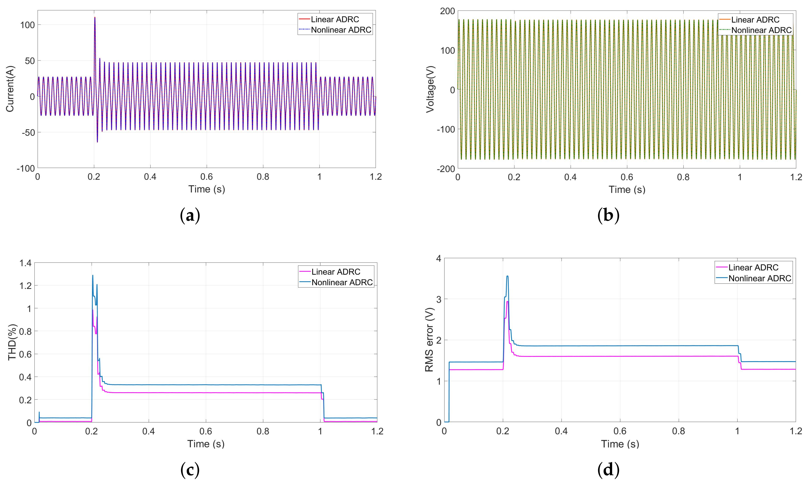
As presented in Figure 10, the DER operation starts with a simple linear load, and then a second nonlinear load was added at t = 0.2 s for a period of 0.8 s. Figure 10a,b present the output current and voltage of the inverter controlled by a linear and nonlinear ADRC, respectively. It can be seen from these simulation results that the linear and nonlinear ADRC approaches have approximately the same performance and efficiency in controlling the inverter with high accuracy. The impact of using a simple error or a nonlinear function “fal” in the control law and the observer can be seen in Figure 10c,d, where the THD variation and the RMS error of the linear regulator are less than the nonlinear one. In both cases, the THD does not exceed the limit of 5 % (set by the IEC standards), and the RMS error is less than 3 % during transient and does not exceed the 1.5 % in the steady state.
The performance, stability, accuracy, and efficiency of the two controllers can be considered to be identical for DER control even with the presence of nonlinear loads. Due to the simplicity of the linear controller structure and based on the simulation results presented above, the linear ADRC is chosen to drive the DER for the rest of this section.

5.2. Linear ADRC Performance under Linear and Nonlinear Loads

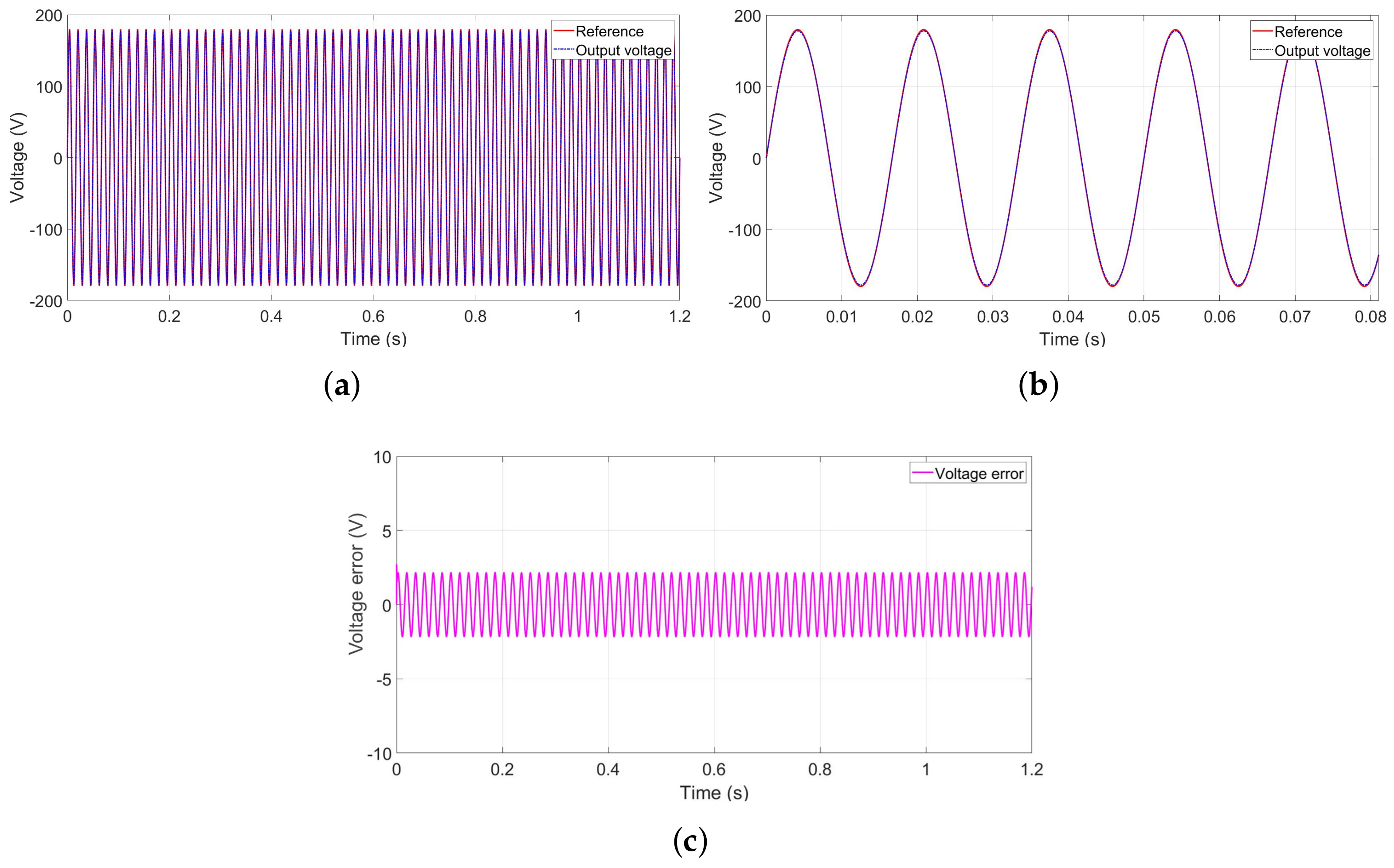
This part deals with performance analysis of linear ADRC to drive the DER system in different operating conditions. Starting with a purely resistive load, the V c voltage perfectly tracks the reference voltage signal, as presented in Figure 11a, with very fast time response and an error less than 3 V during the steady state, as shown in Figure 11b,c.
To investigate the robustness of the ADRC controllers against load profile, several simulations have been conducted. Figure 12 presents the simulation results with inductive load, which has been added to the first load at t = 0.1 s. It can be seen that the ADRC regulator has a high accuracy even with the inductive load, as shown in Figure 12a,b, with an average error that does not exceed 4 % of the RMS value, as presented in Figure 12c. Then, the inverter is used to supply a capacitive load. It can be concluded from the simulation results introduced by Figure 13 that the ADRC regulator shows robust capability, as it has the ability to adapt to different operating conditions for several load profiles. The performance of the proposed control technique can be justified by the current signal presented in Figure 14, which describes the output current signal in the case of resistive, inductive, and capacitive loads.
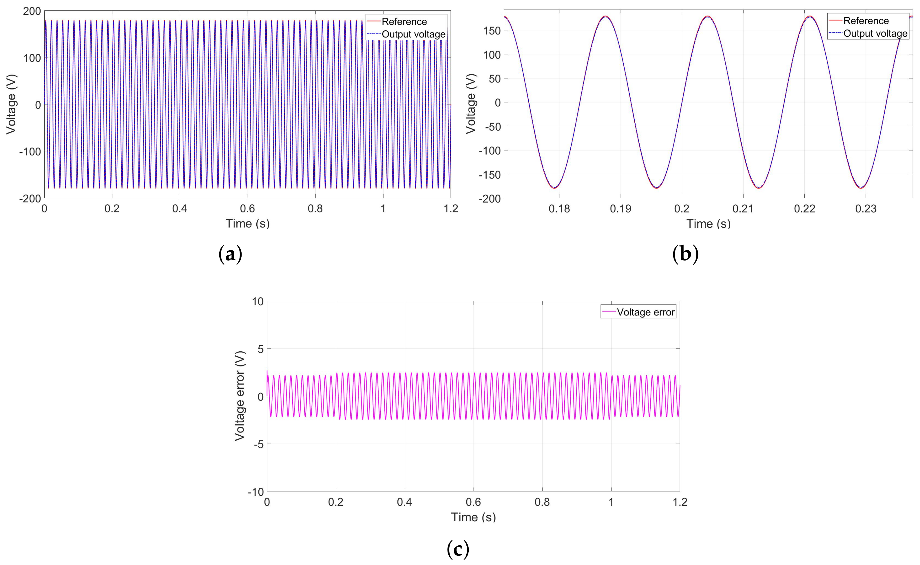
Nonlinear loads have been also considered in this study. Simulations show high performance, as depicted by Figure 15a and Figure 16a. Indeed, the output voltage tracks the reference voltage with high accuracy, even with the connection and disconnection of nonlinear loads. Figure 15b and Figure 16b provide a zoom in during a transient state when adding the first and second nonlinear loads. At this instant, the voltage error presents a small variation less than 10 V , the decrease in which tends to a steady-state condition, with an error that does not exceed 5 V , as shown by Figure 15c and Figure 16c.
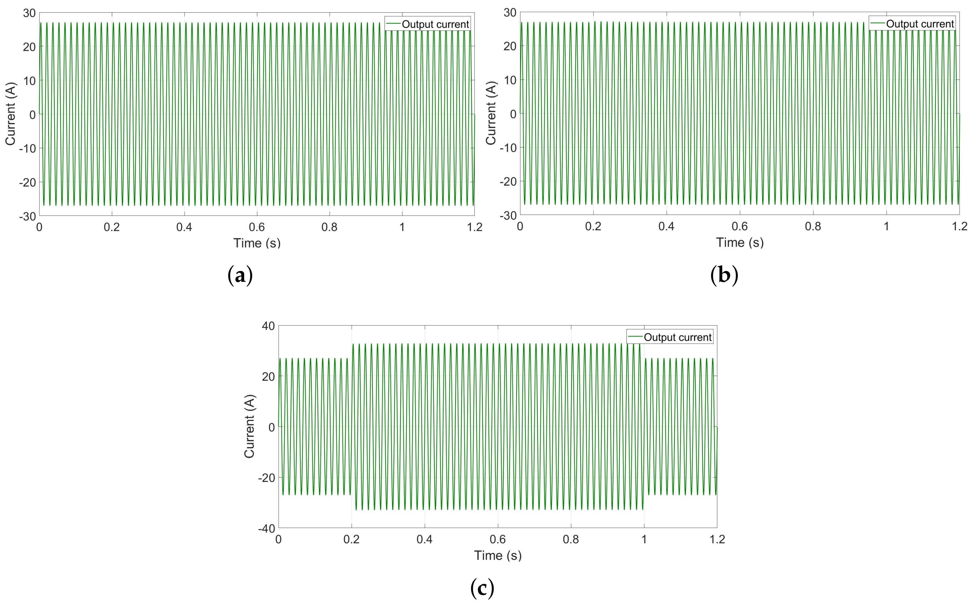
Load profile and load variations have an impact on the current delivered by DER and consequently on the voltage waveform. Figure 17 gives the current variation in the case of linear and nonlinear loads. It appears from these results that the ADRC used to control the current allows compensating for these disturbances and enhances the voltage signal waveform. Figure 18 and Figure 19 depict the THD and the RMS variation for transient and steady-state conditions. It seems from these results that THD and RMS value error comply with the IEC standards, where the THD’s variation is in the limit of 1 % , and the RMS error does not exceed 4 % .

5.3. Parameter Variation and ADRC Performance Analysis

To further prove the robustness and the efficiency of the ADRC approach, further simulations have been conducted under system parameter uncertainty. Indeed, DER parameters are supposed to be known when deriving control laws using classical approaches. However, these parameters are usually uncertain due to parametric variations due to aging, operating conditions, and internal and external disturbances. In the following, simulation results are presented considering the system behavior in the case of uncertainty of the RLC filter’s parameters.
Figure 20a–c present the impact of the resistor, inductance, and capacitor variation on the filter’s output current. It can be noted that uncertainty in those parameters slightly affects the system during the transient state, then the system quickly converges to the reference value. Consequently, the ADRC controller is robust to system parameter variations due to its ability to estimate and compensate for any kind of disturbances due to parametric variation or uncertainty or even external disturbances (termed total disturbances). This fact provides the ADRC controller high performance capability, robustness against internal and external disturbances, and efficiency in delivering a voltage source in microgrid-based DER complying with international standards.

5.4. Discussion

The achieved results underscore the efficacy of the implemented Active Disturbance Rejection Control (ADRC) controllers in attaining the prescribed control objectives. These controllers exhibit interesting performance in tracking the output voltage sinusoidal waveform, even under challenging operating conditions. The study comprehensively explores harsh scenarios, encompassing nonlinear loads and uncertainties in the parameters of the Voltage Source Inverter in the microgrid.
Despite the observable impact of harmonic loads on the control signal and occasional spikes in the output voltage waveforms, the average control error remains within an acceptable range. These simulation results highlight ADRC’s robustness as a control scheme, although certain limitations are evident. The intricate nature of external disturbances encourages users to increase observer and controller bandwidths for enhanced disturbance rejection and reference tracking. However, practical constraints such as finite actuation capabilities, sampling time, and inherent limitations in the ADRC structure necessitate a compromise in real-world applications.
Several constraints can be taken into account while dealing with ADRC real-world implementation, encompassing measurement sensors, disturbance rejection capability, parameter uncertainty immunity, and hardware computational cost. The ADRC can be considered as a compelling approach, achieving significant objectives in terms of sinusoidal voltage waveforms and power quality improvement. However, higher hardware computational costs should be required as compared with Proportional-Integral (PI) controllers.

6. Conclusions

This paper presents a robust control strategy based on Active Disturbance Rejection Control (ADRC) for regulating voltage and current in a single Distributed Energy Resource (DER) unit within a microgrid, accommodating both linear and nonlinear loads. The approach involves treating unknown load variations as total disturbances in the controlled system, estimating these disturbances in real time using an extended state observer (ESO). The ESO within the ADRC framework estimates the extended state, encompassing all disturbances, which are then utilized in the feedback control loops through Nonlinear State Error Feedback (NLSEF) implementation.
The results obtained from the study indicate that the employed Active Disturbance Rejection Control (ADRC) controllers effectively achieve the specified control objectives, demonstrating notable success in accurately tracking the sinusoidal waveform of the output voltage. This favorable performance persists under challenging conditions, including the presence of nonlinear loads and uncertainties in Distributed Energy Resource (DER) parameters. Even in scenarios where harmonic loads impact the control signal and occasional spikes occur in the output voltage waveforms, the overall control error remains within a practically acceptable range. These findings are promising, underscoring the potential of the proposed approach to significantly improve power quality in DERs for microgrid applications.
To further validate these results and assess the practical feasibility of the proposed controllers, additional investigations are warranted. Specifically, the implementation of the controllers on lab-scale experimental benchmarks is essential. Subsequent stages would involve exploring the application of this approach in the context of several interconnected DERs, providing a more comprehensive understanding of its real-world efficacy and scalability.
Author Contributions

Conceptualization, A.H., E.E. and A.B.; methodology, A.H., E.E. and A.B.; software, A.H., E.E. and A.B.; validation, A.H., E.E. and A.B.; formal analysis, A.H., E.E. and A.B.; investigation, A.H., E.E. and A.B.; resources, A.H.; data curation, A.H.; writing—original draft preparation, A.H., E.E. and A.B.; writing—review and editing, A.H., E.E., A.B., S.B.E., M.Z. and M.B.; visualization, A.H., E.E. and A.B.; supervision, E.E., A.B., S.B.E., M.Z. and M.B.; project administration, E.E., A.B., S.B.E., M.Z. and M.B.; funding acquisition, E.E., A.B., S.B.E., M.Z. and M.B. All authors have read and agreed to the published version of the manuscript.

Funding

This research received no external funding.

Data Availability Statement

No new data were created or analyzed in this study. Simulation files can be shared on request.

Conflicts of Interest

The authors declare no conflicts of interest.

Abbreviations

The following abbreviations are used in this manuscript:
MGMicrogrid
DERDistributed energy resources
RESRenewable energy resources
DESDistributed energy storage
ADRCActive disturbance rejection control
MEGMicrogrid exchange group
THDTotal harmonic distortion
ESOExtended state observer
NLSEFNon-linear state error feedback
PWMPulse width modulation
MPPTMaximum power point tracking
TDTracking-Differentiator
RMSRoot mean square

References

  1. Smith, M. US Department of energy’s research & development activities on microgrid technologies. In Proceedings of the Vancouver 2010 Symposium on Microgrids, Vancouver, BC, Canada, 21–22 July 2010. [Google Scholar]
  2. Bouzid, A.M.; Guerrero, J.M.; Cheriti, A.; Bouhamida, M.; Sicard, P.; Benghanem, M. A survey on control of electric power distributed generation systems for microgrid applications. Renew. Sustain. Energy Rev. 2015, 44, 751–766. [Google Scholar] [CrossRef]
  3. Soshinskaya, M.; Crijns-Graus, W.H.; Guerrero, J.M.; Vasquez, J.C. Microgrids: Experiences, barriers and success factors. Renew. Sustain. Energy Rev. 2014, 40, 659–672. [Google Scholar] [CrossRef]
  4. García-Ceballos, C.; Pérez-Londoño, S.; Mora-Flórez, J. Integration of distributed energy resource models in the VSC control for microgrid applications. Electr. Power Syst. Res. 2021, 196, 107278. [Google Scholar] [CrossRef]
  5. Chhor, J.; Sourkounis, C. Optimal voltage control strategy for grid-feeding power converters in AC microgrids. Electr. Power Syst. Res. 2019, 176, 105945. [Google Scholar] [CrossRef]
  6. Ibrahim, S.; Cramer, A.M.; Liao, Y. Integrated control of voltage regulators and distributed generation inverters. Electr. Power Syst. Res. 2019, 169, 45–52. [Google Scholar] [CrossRef]
  7. Liu, S.R.; Yang, P.; Xiao, Y.; Liu, D. Algorithm research of deadbeat control for double-stage photovoltaic grid-connected inverter. Power Syst. Prot. Control 2010, 38, 26–29. [Google Scholar]
  8. Teng, G.; Xiao, G.; Zhang, Z.; Qi, Y.; Lu, Y. A single-loop current control method for LCL-filtered grid-connected inverters based on the repetitive controller. Proc. CSEE 2013, 33, 13–21. [Google Scholar]
  9. Zhang, R.; Chen, Z. PI parameter setting of voltage type PWM rectifier. Chin. J. Power Sources 2014, 38, 941–942. [Google Scholar] [CrossRef]
  10. Rahman, M.M.; Biswas, S.P.; Hosain, M.K.; Sheikh, M.R.I. A second order high performance resonant controller for single phase islanded microgrid. In Proceedings of the 2019 4th International Conference on Electrical Information and Communication Technology (EICT), Khulna, Bangladesh, 20–22 December 2019; pp. 1–6. [Google Scholar]
  11. Alkahtani, A.A.; Alfalahi, S.T.; Athamneh, A.A.; Al-Shetwi, A.Q.; Mansor, M.B.; Hannan, M.; Agelidis, V.G. Power quality in microgrids including supraharmonics: Issues, standards, and mitigations. IEEE Access 2020, 8, 127104–127122. [Google Scholar] [CrossRef]
  12. He, J.; Li, Y.W.; Wang, R.; Zhang, C. Analysis and mitigation of resonance propagation in grid-connected and islanding microgrids. IEEE Trans. Energy Convers. 2014, 30, 70–81. [Google Scholar] [CrossRef]
  13. Mohammadi, F.; Mohammadi-Ivatloo, B.; Gharehpetian, G.B.; Ali, M.H.; Wei, W.; Erdinç, O.; Shirkhani, M. Robust control strategies for microgrids: A review. IEEE Syst. J. 2021. [Google Scholar] [CrossRef]
  14. Ornelas-Tellez, F.; Rico-Melgoza, J.J.; Espinosa-Juarez, E.; Sanchez, E.N. Optimal and robust control in DC microgrids. IEEE Trans. Smart Grid 2017, 9, 5543–5553. [Google Scholar] [CrossRef]
  15. Araújo, R.E.; Leite, V.; Freitas, D.S. Modelling and simulation of power electronic systems using a bond graph formalism. In Proceedings of the 10th Mediterranean Conference on Control and Automation (MED2002), Lisbon, Portugal, 9–12 July 2002. [Google Scholar]
  16. Bacha, S.; Munteanu, I.; Bratcu, A.I. Generalized Averaged Model. In Power Electronic Converters Modeling and Control; Springer: Berlin, Germany, 2014; pp. 97–147. [Google Scholar]
  17. Kwon, J.; Wang, X.; Bak, C.L.; Blaabjerg, F. Comparative evaluation of modeling methods for harmonic stability analysis of three-phase voltage source converters. In Proceedings of the PCIM Europe 2015 International Exhibition and Conference for Power Electronics, Intelligent Motion, Renewable Energy and Energy Management, Nuremberg, Germany, 19–21 May 2015; pp. 1–9. [Google Scholar]
  18. Suntio, T.; Messo, T.; Puukko, J. Power Electronic Converters: Dynamics and Control in Conventional and Renewable Energy Applications; John Wiley & Sons: Hoboken, NJ, USA, 2017. [Google Scholar]
  19. Wen, B.; Boroyevich, D.; Burgos, R.; Mattavelli, P.; Shen, Z. Analysis of DQ small-signal impedance of grid-tied inverters. IEEE Trans. Power Electron. 2015, 31, 675–687. [Google Scholar] [CrossRef]
  20. Cespedes, M.; Sun, J. Impedance modeling and analysis of grid-connected voltage-source converters. IEEE Trans. Power Electron. 2013, 29, 1254–1261. [Google Scholar] [CrossRef]
  21. Han, J. From PID to active disturbance rejection control. IEEE Trans. Ind. Electron. 2009, 56, 900–906. [Google Scholar]
  22. Castañeda, L.A.; Luviano-Juárez, A.; Chairez, I. Robust trajectory tracking of a delta robot through adaptive active disturbance rejection control. IEEE Trans. Control Syst. Technol. 2014, 23, 1387–1398. [Google Scholar] [CrossRef]
  23. Geng, Z. Superconducting cavity control and model identification based on active disturbance rejection control. IEEE Trans. Nucl. Sci. 2017, 64, 951–958. [Google Scholar] [CrossRef]
  24. Wang, G.; Liu, R.; Zhao, N.; Ding, D.; Xu, D. Enhanced linear ADRC strategy for HF pulse voltage signal injection-based sensorless IPMSM drives. IEEE Trans. Power Electron. 2018, 34, 514–525. [Google Scholar] [CrossRef]
  25. Hezzi, A.; Ben Elghali, S.; Bensalem, Y.; Zhou, Z.; Benbouzid, M.; Abdelkrim, M.N. ADRC-Based Robust and Resilient Control of a 5-Phase PMSM Driven Electric Vehicle. Machines 2020, 8, 17. [Google Scholar] [CrossRef]
  26. Zhou, X.; Wang, J.; Ma, Y. Linear active disturbance rejection control of grid-connected photovoltaic inverter based on deviation control principle. Energies 2020, 13, 3790. [Google Scholar] [CrossRef]
  27. He, H.; Si, T.; Sun, L.; Liu, B.; Li, Z. Linear active disturbance rejection control for three-phase voltage-source PWM rectifier. IEEE Access 2020, 8, 45050–45060. [Google Scholar] [CrossRef]
  28. Cao, Y.; Zhao, Q.; Ye, Y.; Xiong, Y. ADRC-based current control for grid-tied inverters: Design, analysis, and verification. IEEE Trans. Ind. Electron. 2019, 67, 8428–8437. [Google Scholar] [CrossRef]
  29. Benrabah, A.; Xu, D.; Gao, Z. Active disturbance rejection control of LCL-filtered grid-connected inverter using Padé approximation. IEEE Trans. Ind. Appl. 2018, 54, 6179–6189. [Google Scholar] [CrossRef]
  30. Zhou, Z.; Elghali, S.B.; Benbouzid, M.; Amirat, Y.; Elbouchikhi, E.; Feld, G. Tidal stream turbine control: An active disturbance rejection control approach. Ocean. Eng. 2020, 202, 107190. [Google Scholar] [CrossRef]
  31. Patterson, C.R. Improved Feedforward Control of a Permanent Magnet Synchronous Motor Using MRAS; University of Arkansas: Fayetteville, AR, USA, 2008. [Google Scholar]
  32. Wang, B.; Shen, Z.; Liu, H.; Hu, J. Linear ADRC direct current control of grid-connected inverter with LCL filter for both active damping and grid voltage induced current distortion suppression. IET Power Electron. 2018, 11, 1748–1755. [Google Scholar] [CrossRef]
  33. Ahi, B.; Haeri, M. Linear active disturbance rejection control from the practical aspects. IEEE/ASME Trans. Mechatron. 2018, 23, 2909–2919. [Google Scholar] [CrossRef]
  34. Herbst, G. A simulative study on active disturbance rejection control (ADRC) as a control tool for practitioners. Electronics 2013, 2, 246–279. [Google Scholar] [CrossRef]
  35. Zhao, L.; Yang, Y.; Xia, Y.; Liu, Z. Active disturbance rejection position control for a magnetic rodless pneumatic cylinder. IEEE Trans. Ind. Electron. 2015, 62, 5838–5846. [Google Scholar] [CrossRef]
  36. Gao, Z. Active disturbance rejection control: A paradigm shift in feedback control system design. In Proceedings of the 2006 American Control Conference, Minneapolis, MN, USA, 14–16 June 2006; p. 7. [Google Scholar]
  37. Abad, G.; Sanchez-Ruiz, A.; Valera-García, J.J.; Milikua, A. Analysis and Design Guidelines for Current Control Loops of Grid-Connected Converters Based on Mathematical Models. Energies 2020, 13, 5849. [Google Scholar] [CrossRef]
  38. Eltawil, M.A.; Zhao, Z. Grid-connected photovoltaic power systems: Technical and potential problems—A review. Renew. Sustain. Energy Rev. 2010, 14, 112–129. [Google Scholar] [CrossRef]
  39. Bouzid, A.E.M.; Zerrougui, M.; Ben Elghali, S.; Beddiar, K.; Benbouzid, M. Robust Resonant Controllers for Distributed Energy Resources in Microgrids. Appl. Sci. 2020, 10, 8905. [Google Scholar] [CrossRef]
Figure 1. Simplified model of DER in islanded mode.
Machines 12 00067 g001
Figure 2. Detailed distributed energy system.
Machines 12 00067 g002
Figure 3. Bode diagram of passively damped and undamped RLC filter.
Machines 12 00067 g003
Figure 4. Active Disturbance Rejection Control structure.
Machines 12 00067 g004
Figure 5. Bode diagram of T 1 ( s ) with control law gain variation.
Machines 12 00067 g005
Figure 6. Bode diagram of T 3 ( s ) with observer’s gain variation.
Machines 12 00067 g006
Figure 7. Bode diagram of T 3 ( s ) with controller’s gain variation.
Machines 12 00067 g007
Figure 8. Block diagram of the ADRC for the DER control in microgrid.
Machines 12 00067 g008
Figure 9. Detailed block diagram of closed-loop system based on ADRC regulator.
Machines 12 00067 g009
Figure 10. DER performance using linear and nonlinear ADRC. (a) Output current signal. (b) Output voltage signal. (c) THD value of DER system output voltage. (d) RMS error of DER system output voltage.
Machines 12 00067 g010
Figure 11. Output voltage with resistive load. (a) Output voltage signal. (b) Zoom in. (c) Output voltage error.
Machines 12 00067 g011
Figure 12. Output voltage with RL load. (a) Output voltage signal. (b) Zoom in. (c) Output voltage error.
Machines 12 00067 g012
Figure 13. Output voltage with RC load. (a) Output voltage signal. (b) Zoom in. (c) Output voltage error.
Machines 12 00067 g013
Figure 14. Output current variation (a) with R load, (b) with RL load, and (c) with RC load.
Machines 12 00067 g014
Figure 15. Output voltage with first nonlinear load. (a) Output voltage signal. (b) Zoom in. (c) Output voltage error.
Machines 12 00067 g015
Figure 16. Output voltage with two nonlinear loads. (a) Output voltage signal. (b) Zoom in. (c) Output voltage error.
Machines 12 00067 g016
Figure 17. Output current variation (a) with linear load, (b) with one nonlinear load, and (c) with two nonlinear loads.
Machines 12 00067 g017
Figure 18. THD variation of output voltage signal (a) with linear load, (b) with one nonlinear load, and (c) with two nonlinear loads.
Machines 12 00067 g018
Figure 19. RMS value of DER system output voltage (a) with linear load, (b) with one nonlinear load, and (c) with two nonlinear loads.
Machines 12 00067 g019
Figure 20. Output current variation (a) with R L variation, (b) with L f variation, and (c) with C f variation.
Machines 12 00067 g020
Table 1. DER system parameters.
ParameterLabelValue
DC bus voltage V D C 520 V
Inductance L f 1 mH
Resistance (inductance side) R L 0.015 Ω
Capacitance C f 250 μ F
Resistance (capacitance side) R c 0 Ω
Uncertain linear load impedance Y m i n Y m a x [5;10,1000] Ω
Frequency60 Hz
RMS output voltage127 V
Table 2. Load parameters.
ParameterLabelValue
Linear load R 1 32.92 Ω
R 2 8.23 Ω
Nonlinear load R n 1 0.73 Ω
R n 2 0.75 Ω
R n 3 37.2 Ω
R n 4 16.5 Ω
C 1 3010 μ F
C 2 9010 μ F
Table 3. Parameters of voltage regulator.
ParameterLabelValue
ESONonlinear factor α 1 0.9
Filter factor δ 1 2
Observer bandwidth ω 0 132.2876
NLSEFNonlinear factor α 2 0.93
Filter factor δ 2 0.01
Controller bandwidth ω c 17.799
Table 4. Parameters of current regulator.
ParameterLabelValue
ESONonlinear factor α 1 0.91
Filter factor δ 1 5
Observer bandwidth ω 0 195.2744
NLSEFNonlinear factor α 2 0.95
Filter factor δ 2 7.5325
Controller bandwidth ω c 39
Disclaimer/Publisher’s Note: The statements, opinions and data contained in all publications are solely those of the individual author(s) and contributor(s) and not of MDPI and/or the editor(s). MDPI and/or the editor(s) disclaim responsibility for any injury to people or property resulting from any ideas, methods, instructions or products referred to in the content.