Abstract
Aiming at the nonlinear and multiple disturbances in the multi-quadcopter UAV system, this paper proposes a leader–follower composite formation control strategy based on an improved super-twisted sliding mode controller (ISTSMC) and a finite-time extended state observer (FTESO). For the designed sliding mode control algorithm, the integral term’s switching function is replaced with a non-smooth term to reduce the vibration in the control, further improving the overall performance of the system. For external disturbances, the finite-time extended state observer achieves rapid and accurate observation of external disturbances. Finally, through formation control experiments, the reliability and superiority of the proposed composite formation controller (CFC) is validated.
1. Introduction
Multi-quadcopter UAV cooperative formation control is a hot topic in the current research on multi-agent control. Compared to a single quadcopter UAV, multi-quadcopter formations offer numerous advantages, such as greater field of view, heavier flight loads, and higher mission tolerance. After years of continuous exploration by researchers, current methods for quadcopter UAV formation control include leader–follower [1], virtual structure [2], artificial potential field [3] and consistency-based approaches [4]. The leader–follower method is the simplest and most commonly used formation control method. It transforms the formation control problem into a position and yaw error tracking problem, enabling the followers to track the leader. Finally, this method achieves formation maintenance and coordinated flights for multi-quadcopter UAV systems.
Based on the leader–follower formation control strategy, many methods such as PID and adaptive control were used for multi-agent systems in [5,6,7]. For the network of heterogeneous uncertain agents, reference [8] proposes an output feedback model reference adaptive control (MRAC) to deal with the unknown dynamics of the intelligences. Due to its strong robustness, sliding mode control is gradually being utilized in multi-agent formation control. For instance, multi-agent systems such as multiple spacecraft and underwater robots have adopted the sliding mode control method, achieving certain control effectiveness in [9,10,11]. Sliding mode control of quadcopter formation flight was used for the first time in [12]. By improving the sliding mode surface, reference [13] incorporates a fast nonsingular terminal sliding mode surface to achieve finite-time formation control and improve the convergence speed. However, using traditional formation sliding mode control, there was significant vibration in the follower drones. To address the vibration issue in sliding mode control, reference [14] proposed a method using Radial Basis Function (RBF) neural networks to reduce the sliding mode switching gain. Combining neural networks and fast terminal sliding mode control, reference [15] effectively reduces the chattering in sliding mode control and improves the convergence rate and tracking accuracy of the controller. Reference [16] effectively suppresses the vibration effects in sliding mode control by improving the super-twisting convergence rate, reducing the vibration in trajectory tracking for the quadcopter. However, in the aforementioned articles on quadcopter formation control, there is limited discussion on interference issues in complex environments, and these control strategies may not effectively suppress external disturbances. In response to the uncertainty in quadcopter parameters and external disturbances, a control approach that combines disturbance observer and adaptive control methods was proposed in [17]. A new robust safety-critical model predictive control framework has been proposed in [18] for controllers to survive as much as possible under disturbances. Based on nonsingular terminal sliding mode control, reference [19] further integrates a finite-time extended state observer, effectively enhancing the disturbance resistance capability of autonomous underwater vehicles. In recent years, with the development of power electronics technology, neural networks are also gradually used in multi-agent robust tracking control. Aiming at the distributed tracking problem of networked intelligences under external disturbances, reference [20] combines neural networks and the disturbance estimator to propose a novel two-component distributed control scheme. Combining neural network approximator, sliding mode control and improved extended high-gain observer, reference [21] proposes a novel robust bipartite tracking consensus control scheme.
To address the issues of sliding mode vibration and external disturbances, in this paper a composite formation controller is proposed based on the quadrotor UAV dynamic model with a leader–follower formation control structure that combines an improved super-twisting sliding model controller (ISTSMC) with a finite-time extended state observer (FTESO). This controller not only reduces the vibration and errors in the formation control of multi-quadcopter UAV systems by replacing the switching function with a non-smooth term but also enhances the disturbance resistance of the controller through the finite-time extended state observer. Finally, experiments and validation of the quadcopter UAV formation algorithm were conducted based on a motion capture system.
The full paper is structured as follows: Section 2 expresses the dynamic model and composite formation controller (CFC) design. Section 3 is the stability analysis of the controller. Section 4 presents the validation experiments and analysis of the formation algorithm and finally the conclusions are given.
2. Dynamic Modeling and Algorithm Design
2.1. Modeling Design
Choosing the X structure quadcopter as the research subject, based on Newton’s second law and Euler’s equations, the six-degree-of-freedom dynamic model is derived as follows:
where represent the position of the quadcopter relative to the origin of the ground coordinate system. represent the Euler angles of the quadcopter. represent the rotational inertia about the three axes. represent the rotational torques about the three axes. is the mass of the quadcopter body. to represent the external disturbances acting on the quadcopter. is the total lift force generated by the four motors.
Considering Figure 1 and assuming that the leader and followers are flying in formation at the same altitude, the dynamic model for the multi-quadcopter formation can be derived as follows:
where represent the relative distance and yaw between the i-th follower and the leader. represent the position and yaw of the leader. represent the position and yaw of the i-th follower.
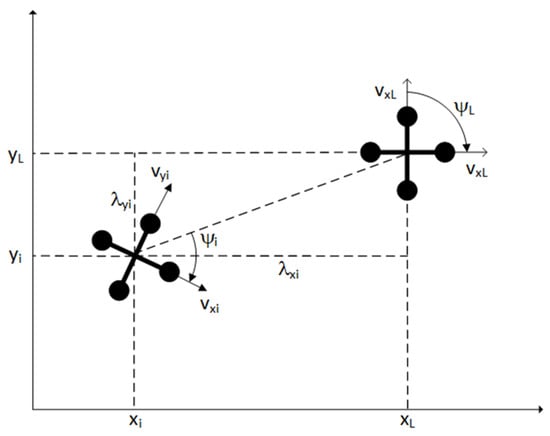
Figure 1.
Leader-follower formation control structure schematic diagram.
2.2. Composite Formation Controller Design
The composite leader–follower control structure designed in this paper is illustrated in Figure 2, which includes the bottom-level control of the following quadcopter UAV and the cooperative control to maintain the formation. Figure 2 illustrates the control process between the i-th follower and the leader, and this sequence can be extrapolated successively to the other followers. While maintaining the desired formation distance and yaw, the cooperative controller continuously drives the actual formation distance and yaw towards the desired formation distance and yaw. This ultimately achieves closed-loop control for the quadcopter UAV system. In addition, to address external disturbances during formation flight, a finite-time extended state observer is designed to enhance the system’s disturbance resistance capability.

Figure 2.
Composite formation control structure diagram.
2.2.1. Observer Design
To simplify the quadcopter dynamics model in Equation (1), the following second-order system model can be obtained:
where represent the non-linear functions, with the index ranging from 1 to 6. represents the i-th follower. , represents the position and attitude for the i-th follower. represents the aggregate disturbance on the channel.
Design of the finite-time extended state observer is as follows [22]:
where are observer gains, and satisfy the condition . is the bandwidth of the observer. As increases, the observer converges faster, but the filtering becomes less effective, with more noise signals passing through; as decreases, the observer converges slower, but the filtering becomes more effective, and the observation disturbance error decreases. is a tunable parameter in the range of −1/3 to 0. correspond to the estimated values of , and the aggregate disturbance on the channel.
2.2.2. Controller Design
The controller error is first defined as:
where .
Designing the general sliding mode surface as:
Combining the improved super-twisting convergence law [23], the specific control law for the followers is as follows:
where are the gains of the controller. is an adjustable parameter, ranging from −0.5 to 0. is the improved convergence rate. is the intermediate variable.
3. Stability Analysis
Assumption 1.
The disturbance and its various order derivatives in each channel of the quadcopter are assumed to be bounded.
Definition 1.
Given numbers and fixed coordinates . If there exists a real number , such that for and , one has , and function is called homogeneous of degree , where are the weights of the coordinates.
Lemma 1.
Suppose that the positive-definite function and function have the same homogeneous degree pertaining to the same dilation weight. Then, there exists a positive constant , such that . In addition, if is positive-definite, one has , where is a positive constant [24].
Lemma 2 [25].
Suppose , then for , one has
Lemma 3 [24].
Define , then for , one has
Lemma 4 [26].
Suppose that , then for , one has
Lemma 5.
Consider the system:
for any constant , where and are positive even and odd integers, respectively, and the constant satisfies that all roots of the characteristic polynomial: fall in the left half-plane of the complex plane, the observation state of the following observer (9) will converge to the true state of the system (8) in finite time.
Combining Equations (3) and (4), the error dynamics of the finite-time extended state observer can be obtained as follows:
where . To obtain the finite convergence time , define , where and .
Design Lyapunov function , one has .
Combining the proof process in [27] and Lemma 5, it can be proved that by choosing the appropriate observer parameters. Finally, the observer finite convergence time is obtained:
In summary, it is proved that the finite time extended state observer is finite time stable.
From Equations (6) and (7), obtain:
where , modifying the above Equation (11) to:
Let , modifying the above Equation (12) to:
For ease of calculation, obtain:
By Lemma 2 and , obtain:
By Lemma 4, we can obtain:
where .
Designing the Lyapunov function as follows:
Derivative for , one has
By Lemma 3 and (15),
where . Combining the above two equations:
Similarly,
where . Combining the above three equations:
Let . Substituting into the above equation:
Let is a positive constant, , by Assumption 1:
Define:
where is a very small constant.
If , one has:
By Definition 1, we get and are homogeneous of degree pertaining to the dilation weight .
By Lemma 1, one has:
Substituting the above Equation (27) into (24), we get:
To ensure that the system can exist at any initial time with after time T, such that
By Definition 1, we get and are homogeneous of degree pertaining to the dilation weight .
By Lemma 1, one has
From the above, it is known that there exists a time , such that .
If ,one has
By , one has
From the above two equations, it can be concluded that, within a finite time, and will converge to an infinitesimally small range.
4. Experimental Analysis
This paper utilized the MC4000 motion capture camera and system provided by Chingmu Technology, and established a quadcopter formation experimental platform, as shown in Figure 3, to validate the designed composite formation controller. The overall length of the quadcopter formation platform is 5 m, width is 4 m and height is 2.3 m. The experimental quadcopter is a small-scale drone with the K210 chip as the main controller, autonomously developed by the laboratory, as illustrated in Figure 4. Two sets of experiments were conducted. The first set involved anti-disturbance experiments with wind disturbances for the followers. The composite controller was compared with the ISTSMC. The second set involved a triangular formation with one leader and two followers, conducting formation flight experiments along straight lines and circles. The composite controller was compared with the traditional sliding mode formation controller.
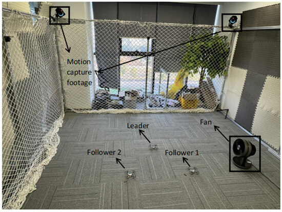
Figure 3.
Formation experiment platform.
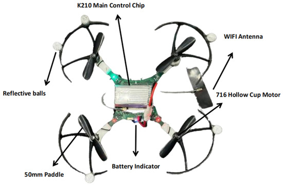
Figure 4.
The quadcopter with the K210 chip as the main controller.

Table 1.
Model parameters of the quadrotor.
In this paper, the experiments set the yaw of the leader and the followers to be the same, so there is no need to carry out the yaw angle control during the formation flight, and at the same time, the two channels x, y have the same controller and observer parameters due to the structure of the quadrotor, as shown in Table 2 below.

Table 2.
Controller and observer parameters.
In SMC and ISTSMC parameters, determines the speed of convergence of the sliding mode. The larger is, the faster the convergence is, but if is too large, it can lead to system instability. In SMC, is the switching function gain, which affects the vibration amplitude of the system. In ISTSMC, the larger is, the smaller the overshoot of the system is; reduces the steady state error of the system; affects the vibration and steady state error of the system. In FTESO, the larger is, the better the response performance of the observer, but if is too large, it increases the observation error; affects the convergence speed of the observer.
To validate the effectiveness of the observer, we positioned the follower to hover directly above the origin at a height of 0.3 m. Additionally, we placed a fan along the x-axis, 0.5 m away from the origin, and allowed it to oscillate left and right within the range of (−80°, 80°), simulating gusty wind disturbance with a period of 4 s. The experimental results are shown in Figure 5 below.
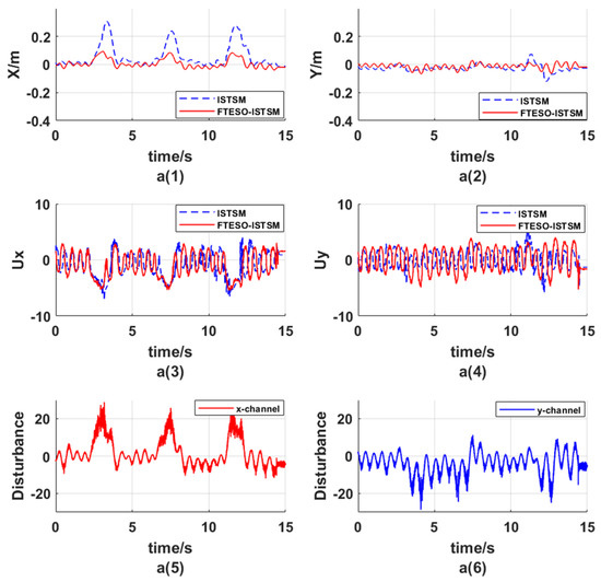
Figure 5.
Results of the wind disturbance resistance experiment. a(1) Position coordinate x; a(2) Position coordinate y; a(3) X channel control output; a(4) Y channel control output; a(5) X channel observation disturbance; a(6) Y channel observation disturbance.
In Figure 5a(1), the follower without the observer, under gusty wind disturbance, exhibited an average maximum deviation of approximately 0.3 m in the x-axis direction. In contrast, the follower with the observer experienced an average maximum deviation of only 0.08 m and its convergence to a steady state was faster by about 2 s. In Figure 5a(2), since the y-axis was not subjected to significant wind disturbances and the focus was mainly on the x-axis, upon comparison, it was observed that the follower with the observer reduced tracking error by approximately 0.02 m. Figure 5a(3) is the x-axis controller output comparison plot, at the fourth, eighth and twelfth seconds, we obviously found that the composite controller compensates the gust disturbance, which effectively reduces the position offset in the x-direction in Figure 5a(1), and improves the controller’s anti-disturbance performance. Figure 5a(4) is the y-axis controller output comparison plot. Figure 5a(5),a(6) show the estimated disturbances for the channels, respectively, and it can be found that the observer accurately observes the external gust disturbance.
To validate the effectiveness of the composite formation controller, we set , = −0.4 m, = −0.4 m, = −0.4 m, = 0.4 m. The formation flight was maintained at a height of 0.3 m, and the leader used a cascade double-loop PID control. Two desired trajectories were given: a 1 m straight-line trajectory in the positive x-axis direction starting from the origin and a circular trajectory with a radius of 0.3 m centered at the origin.
The root cause of chattering in conventional sliding mode control is the presence of discontinuous switching function. To smooth the switching term, the improved super-twisted sliding mode control proposed in this paper replaced the discontinuous switching function with homogeneous function and integral function. The homogeneous function ensures the continuity of the control signal as the switching term approaches zero. The integral function effectively reduces the chattering of the control quantity by integrating the control signal. In addition, ISTSMC replaced the integral function’s discontinuous switching function with a non-smooth term to reduce the vibration in the control, further improving the overall performance of the system. The CFC was compared with the SMC, and the experimental results are shown in Figure 6 and Figure 7 below.
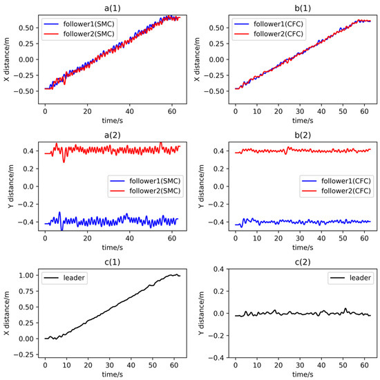
Figure 6.
Results of the formation flight along a straight trajectory. a(1) Position coordinate x of followers; a(2) Position coordinate y of followers; b(1) Position coordinate x of followers; b(2) Position coordinate y of followers; c(1) Position coordinate x of leader; c(2) Position coordinate y of leader.
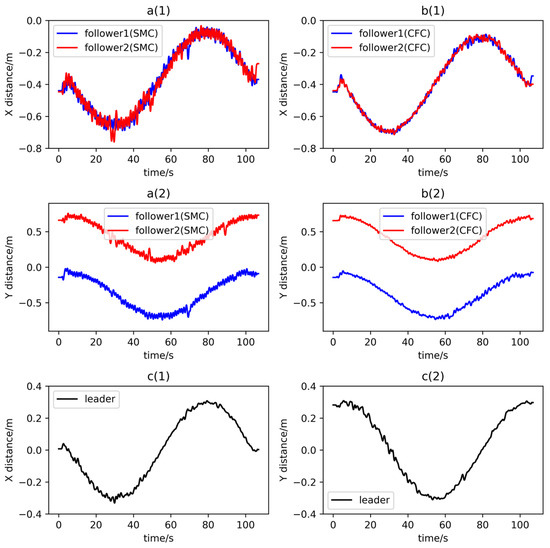
Figure 7.
Results of the formation flight along a circular trajectory. a(1) Position coordinate x of followers; a(2) Position coordinate y of followers; b(1) Position coordinate x of followers; b(2) Position coordinate y of followers; c(1) Position coordinate x of leader; c(2) Position coordinate y of leader.
Figure 6a(1),a(2) and Figure 7a(1),a(2) show the flight trajectories of the two followers using SMC; Figure 6b(1),b(2) and Figure 7b(1),b(2) are the flight trajectories of the two followers using CFC; Figure 6c(1),c(2) and Figure 7c(1),c(2) are flight trajectories of the leader. In the formation flight along a straight trajectory, the average vibration amplitude of the two followers using SMC is around 0.07 m, while the average vibration amplitude of the two followers using CFC is around 0.02 m, which is reduced by 71.4%. In the formation flight along a circular trajectory, the average vibration amplitude of the two followers using SMC is around 0.06 m, while the average vibration amplitude of the two followers using CFC is around 0.025 m, which is reduced by 58.3%. In addition, the trajectories of the two followers using CFC are smoother and more accurate, which improves the stability and accuracy of the formation flight. Observing the experimental results in Figure 6 and Figure 7, it can be seen that whether in a straight-line or circular trajectory, the composite formation controller proposed in this paper effectively reduces the sliding mode chattering.
5. Conclusions
This paper proposes a leader–follower composite formation control strategy for quadcopter UAV systems. The controller integrates an improved super-twisted sliding mode controller (ISTSMC) and a finite-time extended state observer (FTESO), effectively reducing vibration in sliding mode control and enhancing the controller’s disturbance resistance. Experimental results validate the effectiveness of the composite formation controller in reducing chattering and resisting disturbances and improve the stability and accuracy of formation flight.
Author Contributions
X.Z., resources, conceptualization, methodology, project administration; S.H., methodology, data curation, writing—review and editing, supervision; Y.Y., methodology, validation, writing—original draft preparation, visualization, software; Z.S., supervision, project administration, funding acquisition, writing—review and editing. All authors have read and agreed to the published version of the manuscript.
Funding
This research was funded by the National Natural Science Foundation of China (Grant No. 61903186) and the Natural Science Foundation of Jiangsu Province, China (Grant No. BK20190665).
Data Availability Statement
Data are contained within the article.
Conflicts of Interest
The authors declare no conflicts of interest.
References
- Mehmood, Y.; Aslam, J.; Ullah, N.; Chowdhury, M.S.; Techato, K.; Alzaed, A.N. Adaptive robust trajectory tracking control of multiple quad-rotor UAVs with parametric uncertainties and disturbances. Sensors 2021, 21, 2401. [Google Scholar] [CrossRef] [PubMed]
- Askari, A.; Mortazavi, M.; Talebi, H.A. UAV formation control via the virtual structure approach. J. Aerosp. Eng. 2015, 28, 04014047. [Google Scholar] [CrossRef]
- Bennet, D.J.; MacInnes, C.R.; Suzuki, M.; Uchiyama, K. Autonomous three-dimensional formation flight for a swarm of unmanned aerial vehicles. J. Guid. Control. Dyn. 2011, 34, 1899–1908. [Google Scholar] [CrossRef][Green Version]
- Zheng, D.; Zhang, H.; Andrew Zhang, J.; Li, Y. Consensus of the second-order multi-agent systems under asynchronous switching with a controller fault. Int. J. Control. Autom. Syst. 2019, 17, 136–144. [Google Scholar] [CrossRef]
- Ali, Z.A.; Israr, A.; Alkhammash, E.H.; Hadjouni, M. A leader-follower formation control of multi-UAVs via an adaptive hybrid controller. Complexity 2021, 2021, 9231636. [Google Scholar] [CrossRef]
- Cao, L.; Liu, G.P.; Zhang, D.W. A leader-follower formation strategy for networked multi-agent systems based on the PI predictive control method. In Proceedings of the 2021 40th Chinese Control Conference (CCC), Shanghai, China, 26–28 July 2021; pp. 4763–4768. [Google Scholar]
- Jasim, W.; Gu, D. Leader-follower formation suboptimal control for quadrotors. Int. J. Syst. Control. Commun. 2020, 11, 25–51. [Google Scholar] [CrossRef]
- Rosa, M.R. Adaptive synchronization for heterogeneous multi-agent systems with switching topologies. Machines 2018, 6, 7. [Google Scholar] [CrossRef]
- Zhang, N.; Zhang, Y.; Zhang, R. Attitude control of spacecraft formation flying based on nonsingular fast terminal sliding mode control with adaptive fuzzy tuning technique. In Proceedings of the 2021 40th Chinese Control Conference (CCC), Shanghai, China, 26–28 July 2021; pp. 112–117. [Google Scholar]
- Tian, L.; Li, Q.; Hua, Y.; Dong, X.; Li, Q.; Ren, Z. Finite-time time-varying group formation tracking for second-order multiagent systems by continuous integral sliding mode. In Proceedings of the 2020 Chinese Control and Decision Conference (CCDC), Hefei, China, 22–24 August 2020; pp. 3790–3795. [Google Scholar]
- Gao, Z.; Guo, G. Fixed-time sliding mode formation control of AUVs based on a disturbance observer. IEEE/CAA J. Autom. Sin. 2020, 7, 539–545. [Google Scholar] [CrossRef]
- Mercado, D.A.; Castro, R.; Lozano, R. Quadrotors flight formation control using a leader-follower approach. In Proceedings of the 2013 European Control Conference (ECC), Zurich, Switzerland, 17–19 July 2013; pp. 3858–3863. [Google Scholar]
- Nguyen, N.P.; Park, D.; Ngoc, D.N.; Xuan-Mung, N.; Huynh, T.T.; Nguyen, T.N.; Hong, S.K. Quadrotor formation control via terminal sliding mode approach: Theory and experiment results. Drones 2022, 6, 172. [Google Scholar] [CrossRef]
- Zhang, H.; Du, M.; Bu, W. Sliding mode controller with RBF neural network for manipulator trajectory tracking. IAENG-Ternational J. Appl. Math. 2015, 45, 334–342. [Google Scholar]
- Truong, T.N.; Vo, A.T.; Kang, H.J. A model-free terminal sliding mode control for robots: Achieving fixed-time prescribed performance and convergence. ISA Trans. 2023. [Google Scholar] [CrossRef] [PubMed]
- Wu, W.; Xin, J.; Tang, Y. Vision-based trajectory tracking control of quadrotors using super twisting sliding mode control. Cyber-Phys. Syst. 2020, 6, 207–230. [Google Scholar] [CrossRef]
- Yang, Z.J. Adaptive robust output feedback control for attitude tracking of quadrotor unmanned aerial vehicles. Int. J. Adapt. Control. Signal Process. 2021, 35, 2075–2093. [Google Scholar] [CrossRef]
- Yan, Y.; Wang, X.F.; Marshall, B.J.; Liu, C.; Yang, J.; Chen, W.H. Surviving disturbances: A predictive control framework with guaranteed safety. Automatica 2023, 158, 111238. [Google Scholar] [CrossRef]
- Ali, N.; Tawiah, I.; Zhang, W. Finite-time extended state observer based nonsingular fast terminal sliding mode control of au-tonomous underwater vehicles. Ocean. Eng. 2020, 218, 108179. [Google Scholar] [CrossRef]
- Li, W.; Qin, K.; Chen, B.; Lin, B.; Shi, M. Passivity-based distributed tracking control of uncertain agents via a neural network combined with UDE. Neurocomputing 2021, 449, 342–356. [Google Scholar] [CrossRef]
- Li, W.; Qin, K.; Li, G.; Shi, M.; Zhang, X. Robust bipartite tracking consensus of multi-agent systems via neural network combined with extended high-gain observer. ISA Trans. 2023, 136, 31–45. [Google Scholar] [CrossRef]
- Shen, Y.; Xiao, X. Semi-global finite-time observers for nonlinear systems. Automatica 2008, 44, 3152–3156. [Google Scholar] [CrossRef]
- Hou, Q.; Ding, S.; Yu, X.; Mei, K. A super-twisting-like fractional controller for SPMSM drive system. IEEE Trans. Ind. Electron. 2021, 69, 9376–9384. [Google Scholar] [CrossRef]
- Qian, C.; Li, J. Global output feedback stabilization of upper-triangular nonlinear systems using a homogeneous domination approach. Int. J. Robust Nonlinear Control. IFAC-Affil. J. 2006, 16, 441–463. [Google Scholar] [CrossRef]
- Ding, S.; Park, J.H.; Chen, C.C. Second-order sliding mode controller design with output constraint. Automatica 2020, 112, 108704. [Google Scholar] [CrossRef]
- Mei, K.; Ding, S. HOSM controller design with asymmetric output constraints. Sci. China Inf. Sci. 2022, 65, 189202. [Google Scholar] [CrossRef]
- Razmjooei, H.; Shafiei, M.H. A new approach to design a finite-time extended state observer: Uncertain robotic manipulators application. Int. J. Robust Nonlinear Control. 2021, 31, 1288–1302. [Google Scholar] [CrossRef]
Disclaimer/Publisher’s Note: The statements, opinions and data contained in all publications are solely those of the individual author(s) and contributor(s) and not of MDPI and/or the editor(s). MDPI and/or the editor(s) disclaim responsibility for any injury to people or property resulting from any ideas, methods, instructions or products referred to in the content. |
© 2024 by the authors. Licensee MDPI, Basel, Switzerland. This article is an open access article distributed under the terms and conditions of the Creative Commons Attribution (CC BY) license (https://creativecommons.org/licenses/by/4.0/).