Abstract
Kinematic control of redundant serial manipulators has been carried out for the past half century based primarily on a generalized inverse velocity formulation that is known to have mathematical deficiencies. A recently developed inverse kinematic configuration mapping is employed in an operational configuration space differentiable manifold formulation for redundant-manipulator kinematic control with obstacle avoidance. This formulation is shown to resolve deficiencies in the generalized inverse velocity formulation, especially for high-degree-of-redundancy manipulators. Tracking a specified output trajectory while avoiding obstacles for four- and twenty-degree-of-redundancy manipulators is carried out to demonstrate the effectiveness of the differentiable manifold approach for applications with a high degree of redundancy and to show that it indeed resolves deficiencies of the conventional generalized inverse velocity formulation in challenging applications.
1. Introduction
1.1. Basics of Redundant-Serial-Manipulator Kinematics
A serial manipulator is comprised of a chain of bodies that are connected by single-degree-of-freedom joints. Joint relative input coordinates between bodies in the chain define the configuration of outboard bodies relative to their inboard counterparts. The terminal body in the chain is the end effector, whose output coordinates characterize manipulator working capability and are defined as twice continuously differentiable functions of input coordinates, in the form of forward kinematic mapping.
Input coordinates are independent generalized coordinates [1] that define the configuration of the underlying mechanism, and output coordinates of the end effector, with , define functionality of the kinematically redundant manipulator. Here, refers to k-dimensional Euclidean vector space with elements in the form of column vectors , where superscript denotes matrix transpose. Bold characters denote vectors and matrices.
An input–output pair that satisfies Equation (1) defines a manipulator configuration, denoted . The manipulator configuration space is defined as
As observed in [2], X is the graph of Equation (1). As such, under moderate regularity conditions, it is a differentiable manifold with the single chart , where [2]. This manifold, however, contains information only on forward kinematics and no information regarding inverse kinematics.
The manipulator configuration space often contains singular configurations relative to inverse kinematics. If the rank of the Jacobian matrix of derivatives of with respect to , defined as the matrix , is less than m at a configuration , then in a neighborhood of , there exists no continuously differentiable set-valued inverse kinematic mapping with arbitrary parameters [3,4]. To avoid difficulties associated with inverse kinematic singular configurations in X, the regular configuration space is defined as
In , the manipulator degree of redundancy is .
1.2. A Four-Degree-of-Redundancy Manipulator
Most applications of redundant manipulators have just one degree of redundancy, i.e., r = . To relate the mathematical formulation to a real manipulator, consider the planar serial manipulator of Figure 1 that has inputs, , and two outputs, , hence degrees of redundancy.
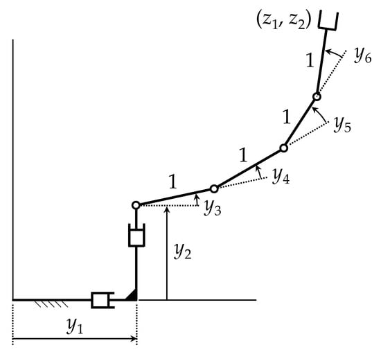
Figure 1.
Serial manipulator with a degree of redundancy of 4.
Using the notation , the forward kinematic mapping of Equation (1) is
with the full-rank Jacobian, for all ,
1.3. Generalized-Inverse-Velocity-Based Redundancy Resolution
Differentiating Equation (1) with respect to time yields the kinematic velocity equation:
Since Equation (6) is linear in velocity, for a given configuration, it may be thought that analysis in the linear velocity space is easier than in the nonlinear regular configuration space of Equation (3). When and the manipulator is nonredundant, this may in fact be the case. In , if m = n, the manipulator is nonredundant, is square and nonsingular, and there is a unique solution of Equation (6) for ,
In this special case, Equation (7) is an ordinary differential equation (ODE). For specified continuous and initial condition , the initial-value problem with Equation (7) has a unique solution in a neighborhood of .
For redundant manipulators with , attractive properties of ODE for Equation (6) are no longer available. At a redundant manipulator configuration , has full rank, but is not a square matrix, and Equation (6) with given cannot be solved for a unique value of . In this case, Equation (6) is not an ODE in y. It is a Pfaffian differential equation [5] that behaves more like a partial differential equation than an ODE. While the ODE of Equation (7) with m = n has a general solution for y that depends on n arbitrary constants, a general solution of Equation (6) for y with n > m depends on arbitrary vector functions [5]. As shown in [4], trading the nonlinear manipulator equations of Equations (2) and (3) for the Pfaffian differential equation of Equation (6) is a questionable decision.
A generalized-inverse-velocity-based redundancy resolution formulation for Equation (6) was introduced by Whitney [6] half a century ago in an attempt to create an ODE formulation for redundant-manipulator kinematics. At a configuration with n > m, has full rank and the Moore–Penrose generalized inverse [6,7,8] is defined as
Direct manipulation verifies that , and
satisfies Equation (6) for arbitrary . While of Equation (9) satisfies Equation (6), it does not provide a solution of Equation (1), and there is no reason to believe Equations (6) and (9) are equivalent.
1.4. Problems with Generalized-Inverse-Velocity-Based Redundancy Resolution
In the redundant-manipulator literature, e.g., [6,7,8,9,10] and references cited therein, Equation (9) has been treated as a differential equation that relates output to input. It has been analytically and computationally shown, however, that use of Equation (9) leads to irregularities in predicted manipulator performance [4,11,12,13], including numerical drift, nonholonomic behavior, and divergence of computation. Analysis has shown that use of the generalized inverse of Equation (8) leads to nonholonomic equations of redundancy resolution that create systematic noncyclicity of the manipulator [12,13], i.e., a periodic output trajectory maps into a nonperiodic input trajectory. While some effort has been devoted to creating generalized inverses that overcome these problems, e.g., [14,15] and references cited therein, no comprehensive result has been reported. A treatment based on concepts similar to those employed herein is shown to partially resolve the noncyclicity problem [16]. Theoretical and numerical results presented in [4,16] complement the literature cited and show that the generalized inverse velocity approach to manipulator redundancy resolution is fundamentally flawed.
While the foregoing analyses of deficiencies of the generalized inverse velocity approach do not focus specifically on obstacle avoidance, the inaccuracies implied cast doubt on use of the approach for kinematic control with obstacle avoidance. In particular, no inverse kinematic mapping at the configuration level is defined with free parameters, which means that an indirect velocity approach to obstacle avoidance must be employed. Since obstacle avoidance occurs in configuration space, not in velocity space, an adaptation of generalized inverse velocity differential equations must be created to treat an application that is stated in terms of manipulator configuration.
1.5. Manipulator Trajectory Planning and Obstacle Avoidance
An extensive literature on kinematically redundant manipulator trajectory planning and kinematic control appeared in the last quarter of the 20th century, based primarily on the generalized inverse velocity representation of Equation (9), e.g., [6,7,8,9,10] and references cited therein. The most basic kinematic control formulation seeks to use manipulator redundancy to cause manipulator output z(t) to follow a desired output trajectory and to satisfy constraints such as avoiding collision of manipulator links with obstacles. Objectives and constraints in these applications are most naturally stated in terms of manipulator input and output coordinates, rather than velocities. The apparent simplicity of the velocity equations of Section 1.3, with the redundancy-related arbitrary velocity of Equation (9), however, has led research and development engineers to adopt the generalized inverse velocity mapping of Equation (9) to address the kinematic control objective, e.g., [7,8] and references cited therein.
Quite recently, a configuration-based inverse kinematic mapping for kinematically redundant serial manipulators has been presented that avoids deficiencies associated with the generalized inverse velocity mapping approach [3,4]. This method is summarized in Section 3 and applied for manipulator path planning with obstacle avoidance.
2. Generalized-Inverse-Velocity-Based Kinematic Control and Obstacle Avoidance
The conventional approach to satisfying constraints such as obstacle avoidance using the generalized inverse velocity approach is the projected-gradient method, employing the second term of Equation (9), i.e., the null space term, to minimize a cost function that models the secondary criterion. This is performed by defining
with , where , and projecting it onto the null space of the Jacobian matrix by means of the projector of Equation (9) [17]. As a result, y(t) will move in a direction that decreases f(y), without affecting the desired output trajectory , i.e., self-motion. When the constraint is to avoid obstacles, can be chosen as any function that penalizes manipulator link proximity to obstacles [18]. For example, if f(y) is defined as
where is the minimum distance between link i and obstacle j, manipulator links will tend to move away from obstacles.
Another approach to obstacle avoidance using the generalized inverse velocity method consists in choosing as an input velocity that attempts to generate an escape velocity at the point of the manipulator that is closest to the obstacle, where such escape velocity is directed away from the obstacle. This requires yet another generalized inversion of the Jacobian matrix that maps input velocities to the velocity of [19]. Alternatively, Lee and Buss [18] use the transpose of that has lower computational burden than generalized matrix inversion and avoids problems with singularities, at the expense of accuracy in generation of the desired escape velocity. This is not crucial, as long as the link moves away from the obstacle.
When a hierarchy of tasks exists, i.e., there is a primary task and several secondary tasks with different levels of priority, where each task has an associate Jacobian, lower-priority tasks are optimized by projecting velocities on the null space of higher-priority tasks [20]. This hierarchy of projections is used in the method of Saturation in the Null Space (SNS) [21], which saturates input velocities that reach their limits and slows the task, i.e., scales time, to restore feasibility if such saturations render the desired task infeasible. The SNS method can achieve obstacle avoidance by adapting limits of joint velocities near obstacles [22] or by augmenting joint velocities with velocities of control points on links of the manipulator and limiting these velocities in the vicinity of obstacles [23]. The SNS method is usually formulated at the velocity level, but it has been extended in [24,25] to function also at acceleration and torque levels.
In any case, the foregoing methods are based on use of the generalized inverse in the velocity equation, which leads to deficiencies discussed in Section 1.4. Moreover, these methods operate at velocity or acceleration levels, whereas constraints such as obstacle avoidance are naturally defined at the configuration level. This requires recasting these constraints approximately to set bounds on velocities, e.g., joint range limits are typically reformulated as bounds on joint velocities by using a forward difference approximation of the derivative of configuration [22], which may lead to violation of these constraints.
Use of the generalized inverse in the velocity equation is not a robust way to handle obstacle avoidance, because it is based on a velocity equation that needs to be numerically integrated to obtain the configuration of the manipulator. For example, if of Equation (10) is inserted into Equation (9), which is integrated numerically with a given time step Δt, the resulting trajectory of the manipulator may not be feasible. This is because, as time progresses, Equation (9) is integrated, and the cost function may not be minimized at a sufficiently high rate to avoid obstacles. Indeed, if the minimization of is not performed sufficiently quickly as the manipulator approaches obstacles, penetration of an obstacle will occur that will produce a zero denominator in Equation (11), i.e., for some (i,j), and this will lead to failure of numerical integration. As is demonstrated in Section 4.1.2 and Section 4.2.3, it is necessary to carefully select the values of Δt (time step) and k (gain appearing in Equation (10)). In fact, as shown, it may be necessary to use extremely small values of Δt and k to obtain motion that is free of obstacle penetration. On the one hand, simulating the full trajectory using a small Δt means long computation times. On the other hand, when using Equation (9) for real-time kinematic control of the manipulator, a small Δt imposes extreme demands on the control hardware, which must be able to operate at such small sample times.
3. Operational Configuration Space Kinematic Control and Obstacle Avoidance
To replace the generalized inverse velocity formulation of Section 2 with a configuration space formulation, it is required that a set-valued inverse configuration kinematic mapping be constructed, i.e., that a solution of Equation (1) be found with an arbitrary vector of parameters . Such a mapping has been presented in [3] and extended in [4] on an operational space differentiable manifold, as summarized in this section.
3.1. Inverse Configuration Kinematics
The entire regular configuration space cannot, in general, be characterized by a single continuously differentiable inverse kinematic mapping. The only practical global inverse kinematic representation is based on concepts of differential geometry [2] that employ local representations on open subsets , whose union is the entire regular configuration space, i.e., . In each , there is a base point about which the inverse kinematic mapping is constructed. The inverse kinematic mapping process that follows takes place on each . For a given j and base point in , define the matrix and an matrix such that
where is computed as a matrix whose columns form an orthonormal basis of the null space of , e.g., in MATLAB, using singular-value decomposition [26]. The matrices are defined to be constant on . Note from the second equation of Equation (12) that and . Since has full rank, so do and . Further, since , the columns of are orthogonal to the columns of and vice-versa. The n linearly independent columns of (m columns) and ( columns) therefore span .
Using and of Equation (12), any solution of Equation (1) for y in a neighborhood of can be written in the form
where are values of v and u associated with on the trajectory that first enters . They are introduced to assure continuity of y as a function of v and z. On , and . Note that, at in Equation (13), . To see that there is a unique solution of Equation (1) with y of Equation (13), i.e., a unique solution of
for u as a function of z and v in a neighborhood of and , the derivative of the left side of Equation (14) with respect to u, evaluated at , i.e., at and , using the chain rule of differentiation, is , which is nonsingular. Thus, the implicit-function theorem [27] implies existence of a unique, twice continuously differentiable solution,
of Equation (14) in a neighborhood of . From Equation (13),
This is the desired set-valued inverse configuration kinematic mapping on .
If are periodic of period on , i.e., and , since Equation (16) holds throughout ,
Thus, is periodic of period , and the manipulator is cyclic on . This shows that, with the differentiable manifold formulation, the manipulator is locally cyclic [4,16]. In kinematic control with obstacle avoidance, however, during a transient control time interval in which is activated to resist penetration of an obstacle, it will generally not be periodic. During this time interval, the manipulator will not be locally cyclic. If, after transient action to avoid obstacles, the desired periodic output goes through cycles without control action required to avoid obstacles, i.e., becomes constant, then during these cycles, the manipulator will be locally cyclic.
The role of the function is important in assuring satisfaction of Equation (1). This is in contrast with the generalized inverse velocity approach presented in Section 2, in which Equation (1) is ignored. A computationally efficient iterative method for evaluation of is presented in [3,4]. In this computation, when the number of iterations required for convergence exceeds a specified tolerance, the associated configuration is designated , the associated y, v, and u are designated , , and , a new neighborhood is entered, and the parameterization is redefined. As shown in [28] for dynamic system simulation, less than 0.1% of CPU time and no user interaction are required for reparameterization. For more detail on the process of selecting configurations and reparameterization calculations, see [3,4,28].
For a given output , with arbitrary in a neighborhood of v = , Equation (16) defines a set of input coordinates,
called the manipulator self-motion manifold in input space associated with output . Since is the solution of Equation (14), , for all v in a neighborhood of v = , of Equation (16) maps into , i.e., . Components of the vector are called self-motion coordinates. With arbitrary self-motion coordinates v in a neighborhood of , Equation (16) defines redundant degrees of freedom of the manipulator that enables it to meet requirements that could not be met with a nonredundant manipulator. The restriction of v to a neighborhood of in the foregoing is to meet hypotheses of the implicit-function theorem. As shown in Section 4.1.1 and Section 4.2.2, Equations (16) and (18) may hold for large v in applications.
It is important to note that the self-motion manifold of Equation (18) is defined at the configuration level. Since configuration information is not defined in the generalized inverse velocity formulation, the self-motion manifold and self-motion coordinates cannot be explicitly defined and are not available for obstacle avoidance in that formulation.
3.2. Operational Space Differentiable Manifold
Defining manipulator operational coordinates and functional coordinates , the manipulator regular functional configuration space is
Similar to the definition of the manipulator configuration space of Equation (2) as the product of input and output spaces, the serial manipulator regular functional configuration space is defined as the product of input and operational spaces. This is important in establishing as a differentiable manifold, as presented in [4]. A family of charts (, ) (an atlas) is defined to cover , such that the mappings are compatible and is a differentiable manifold that is parameterized by w [2,4]. The differentiable manifold can thus be parameterized by either y or w. It cannot, however, be parameterized by only output z.
Kinematics on must be carried out on individual charts and transitioned to adjacent charts as manipulator configurations progress along a trajectory in , as shown schematically in Figure 2. Piecewise analysis on charts is unavoidable since, in general, there is no globally valid operational coordinate parameterization of [2]. This attribute of differential geometry that transforms local to global properties of sets and mappings is one of its greatest contributions. The unavoidable reality, however, is that one must adopt local operational space parameterizations, since no global parameterization generally exists.
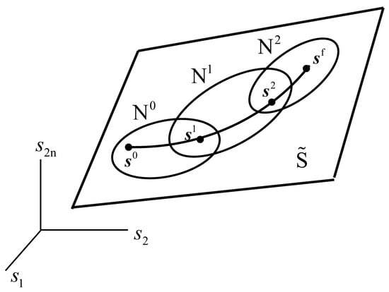
Figure 2.
Trajectory along charts in .
3.3. Differentiable-Manifold Output Trajectory Tracking and Obstacle Avoidance Algorithm
An output trajectory tracking and obstacle avoidance algorithm based on the inverse kinematic mapping of Equation (16) is presented to carry out kinematic control more rigorously and efficiently than with the generalized-inverse-velocity-based method of Section 2. In [3], the inverse mapping was employed to avoid collisions in redundant manipulators using an algorithm that marched along one-dimensional self-motion manifolds. That algorithm, however, is limited to manipulators with a degree of redundancy of one. First, a nominal trajectory for the inputs is selected that yields the desired output trajectory , without exploiting kinematic redundancy. When the manipulator starts to move, it follows this nominal trajectory until a collision is detected at some of the desired output trajectory, i.e., until the intersection of two bodies is not empty. When a collision is detected, the algorithm presented in [3] performs self-motions defined by Equation (18) that keeps , i.e., the self-motion coordinate is varied on a grid with a given step along one direction (or the opposite) of the self-motion manifold until the interference disappears. This algorithm is feasible only when the self-motion manifold is one-dimensional, because one only needs to march along self-motion curves, exhaustively searching until a collision-free configuration is found.
In manipulators with higher degrees of redundancy, such as the manipulator of Section 1.2, the obstacle avoidance algorithm used in [3] is not feasible, because one would need to perform an exhaustive grid search in the higher-dimensional space of self-motion coordinates , which would be computationally prohibitive, e.g., a four-dimensional grid for the manipulator of Section 1.2. The new algorithm employed herein efficiently treats obstacle avoidance using the inverse mapping of Equation (16) for higher degrees of redundancy, as the examples of Section 4.1.1 and Section 4.2.2 demonstrate.
The new algorithm is based on the fact that, in the vicinity of a contact between two bodies, it is possible to define a gap function [29,30] that is the signed distance between the closest points of the two bodies along their common normal. This works even when one of the bodies has a nonsmooth shape and does not have a unique normal at the point of contact [29,30]. Figure 3 illustrates this gap function . Note that is a signed distance, which is positive when the bodies do not intersect, zero when their boundaries touch, and negative when one body has penetrated the other. The gap function depends on the relative pose of the contacting bodies, which is defined by input coordinates, i.e., . Using the inverse mapping of Equation (16), one can write the gap function in terms of the operational coordinates, i.e., .
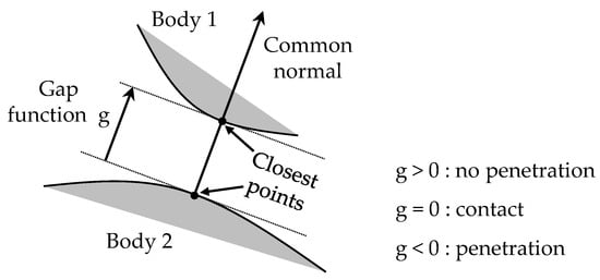
Figure 3.
Definition of gap function .
Taking the foregoing into account, the new algorithm is as follows:
STEP 1: Initialize and select a time step . The desired output trajectory is for . The initial configuration yields the initial desired , i.e., . Construct the inverse mapping of Equation (16) in a neighborhood of , i.e., compute and and initialize = 0 and u = 0. Throughout execution of the algorithm, the self-motion vector v is updated only when necessary to avoid obstacles. If other secondary goals are to be met, the self-motion vector v can be used to optimize these secondary goals. In the present algorithm, the focus is on the use of redundancy only for obstacle avoidance.
STEP 2: Set , solve for as in Section 3.1, and evaluate of Equation (16). Whenever necessary, perform a reparameterization, i.e., a transition between charts illustrated in Figure 2, as outlined in Section 3.2.
STEP 3: For the computed configuration , check if interferences occur, i.e., if any link of the manipulator intersects an obstacle. If no intersections occur, continue with step 4. Otherwise, go to step 5.
STEP 4: Send the collision-free configuration to the controller of the manipulator and proceed to the next time step, i.e., update . If , return to step 2. Otherwise, the desired trajectory has been completed and the algorithm ends.
STEP 5: If the algorithm has reached this step, there exists mechanical interference between the manipulator and at least one obstacle for the current value of , which is obtained from and . Assume that contacts have occurred between links of the manipulator and obstacles. In that case, contacts define gap functions , , which will be negative because obstacles are penetrated. The objective is to find a value of v that renders the gap functions non-negative. This can be formulated as the following nonlinear system:
where is a vector of auxiliary variables that are introduced to transform the desired inequalities into equivalent equalities . Next, Equation (20) is solved for , using the Newton–Raphson (N-R) method [26], where the starting values of v and k for N-R iteration are , i.e., the value that produced the interference that led to this step of the algorithm, and k = 0. Since Equation (20) is c equations in (c + n − m) unknowns, it comprises an underdetermined system. Therefore, when inverting the Jacobian used in the N-R method, the minimum-norm Moore–Penrose pseudoinverse is used, which updates the unknowns r with the vector Δr of minimum norm. The N-R method used to solve Equation (20) is described by Algorithm 1 shown below, where
and is the Jacobian of with respect to r.
| Algorithm 1. Newton–Raphson iterations to solve Equation (20) | |
| 1: | |
| 2: | |
| 3: | do |
| 4: | |
| 5: | |
| 6: | |
| 7: | AND iterations < max_iterations |
Since the increment Δr with minimum norm is used in lines 4–5 of Algorithm 1 to update the unknowns, this favors continuity of the configuration of the manipulator. In fact, as the examples of Section 4 demonstrate, the proposed algorithm generates continuous trajectories for the manipulator, and execution of Algorithm 1 (whose objective is to find a new value of self-motion coordinates v that avoids collisions) takes only a few milliseconds on a modern computer. The N-R method stops when a solution that satisfies Equation (20) is found, or when a maximum of max_iterations is exceeded. In the first case, the algorithm yields a configuration y that is collision-free, and the algorithm jumps to step 4. In the second case, the desired trajectory can be considered as infeasible, because no configuration (sufficiently near to the configuration at the previous time step) can be found to continue executing the trajectory while avoiding obstacles, and the algorithm ends.
4. Numerical Examples
The foregoing theory and computational algorithms are tested in this section using planar examples with four and twenty degrees of redundancy. The selection of planar examples is for ease of analysis and visualization of results. The theory and algorithm of Section 3.3 is equally applicable for spatial and planar manipulators. For an application of the differentiable manifold formulation with a seven degree of freedom spatial redundant serial manipulator, see [3].
4.1. Four-Degree-of-Redundancy Trajectory Tracking and Obstacle Avoidance
4.1.1. Differentiable-Manifold Output Tracking and Obstacle Avoidance
In this section, the method described in Section 3.3 is applied to plan the motion of the manipulator of Section 1.2 that has four degrees of redundancy. The manipulator starts with input , and its end-effector is required to follow the periodic elliptic trajectory
while its links must avoid a circular obstacle centered at (1.5, 2) with radius 0.5. Equation (22) is the parametric equation of an ellipse centered at (x0 = 1.7, y0 = 2.9) with semiaxes a = 2 and b = 0.25, whose longer semiaxis forms an angle of θ = −0.15 rad with the x axis. The end-effector is required to follow three cycles on this ellipse, i.e., t runs from t = 0 to t = 6 π, with a time step of s.
The algorithm described in Section 3.3 is carried out with the following parameters:
- (1)
- Iterations in the method presented in [4] to evaluate stop when .
- (2)
- Iterations in Algorithm 1 stop when or when iterations > 10 = max_iterations.
With these parameters, the algorithm generates the time histories of y(t) and v(t) shown in Figure 4. As this figure shows, the time history of these variables is periodic after the first cycle, where vertical dashed lines separate cycles. In particular, v is constant after the first cycle. It can be seen in Figure 4 that the trajectory of y(t) becomes cyclic when v becomes constant, even before the output trajectory of Equation (22) has completed its first cycle. This locally cyclic behavior is consistent with the theory presented in Section 3.1.
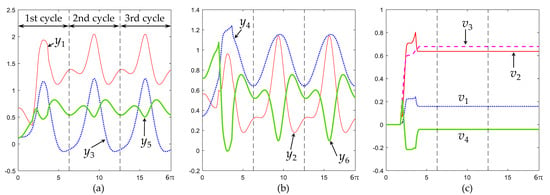
Figure 4.
(a–c) Time history of y(t) and v(t) becomes cyclic after the first cycle, when the end-effector follows Equation (22) while avoiding an obstacle using the obstacle avoidance algorithm of Section 3.3.
Snapshots of the manipulator executing this trajectory are shown in Figure 5. An animation is shown in supplementary video S1 attached. Figure 5a–i show execution of the first cycle. In Figure 5a, the manipulator moves with v = 0 as it approaches the obstacle, until touching it. Then, the algorithm of Section 3.3 starts to actively update v(t) to avoid penetration of the obstacle. Figure 5b–g show how the manipulator continues tracking the desired elliptical trajectory, while some of its links touch the circular obstacle, until contact is lost in Figure 5h and v is no longer updated. After this, the manipulator continues executing the trajectory far from the obstacle until it completes the first cycle, as shown in Figure 5i.
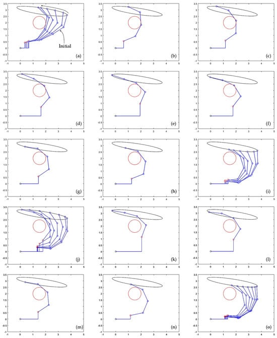
Figure 5.
(a–i) Execution of the first cycle of the desired output trajectory given by Equation (22). (j–o) Execution of the second cycle. Supplementary video S1 attached shows this figure in motion, including a third cycle that is identical to the second one.
Execution of the second cycle begins with the manipulator approaching the obstacle, as illustrated in Figure 5j. As shown in Figure 5k–n, during the second cycle, the manipulator is not in contact with the obstacle except during a very short period of time shown in Figure 5m, in which one of the links becomes tangent to the obstacle. This contact period is very short, as can be better observed in the supplementary animation S1 attached to the paper. After this short contact is lost (Figure 5n), the manipulator continues moving far from the obstacle until completing the second cycle (Figure 5o). The third and subsequent cycles are identical to the second cycle, as shown in Figure 4.
As Figure 4 and Figure 5 show, during the first cycle of the desired trajectory given by Equation (22), the algorithm of Section 3.3 actively updates v(t) to prevent penetration of the obstacle during contact. After contact is lost, v(t) does not need to be further updated and the input trajectory becomes cyclic, by virtue of Equation (17). Interestingly, the constant value that v(t) adopts after contact is lost in the first cycle allows the manipulator to continue repeating subsequent cycles during which contact without penetration occurs only during a very short fraction of the cycle, as illustrated in Figure 5m.
The average time required to run Algorithm 1 is 1.2 milliseconds (time measured on the following CPU running MATLAB R2022b: Intel Core i7-8750H at 2.20 GHz). This is the time required to find a new value of self-motion coordinates that avoids penetration of obstacles every time that such penetration is detected, which demonstrates a rapid correction of the trajectory to avoid obstacles, compatible with real time requirements.
As shown in Figure 5, to prevent obstacle penetration, the algorithm of Section 3.3 keeps the links in contact with the obstacle and moving smoothly around it until contact is lost, as required by the trajectory of the end-effector. If it were necessary to avoid the obstacle without contacting it, leaving some safety distance , then one would only need to change the gap functions in Equation (20) to , making it easier to accurately regulate distance to obstacles than with the generalized-inverse-velocity-based approach, which is illustrated next.
4.1.2. Generalized-Inverse-Velocity Output Tracking and Obstacle Avoidance
In this section, the approach described in Section 2 is used to solve the problem treated in Section 4.1.1, where the manipulator with four degrees of redundancy must track the periodic trajectory given in Equation (22). The manipulator starts at the same configuration as in Section 4.1.1. The same time step, seconds, is used in the present section to numerically integrate Equation (9) using a fourth-order Runge–Kutta integrator [26]. In contrast to the generalized-inverse-velocity-based method, the algorithm of Section 3.3 does not need to perform any numerical integration. The time step in that case is used only to progress in time according to step 4 of the algorithm.
The method described In Section 2 is carried out by numerically integrating with a fixed time step of s. For a given time step , the main parameter that can be tuned in the method of Section 2 is the coefficient k > 0, which adjusts the intensity of the penalty function . A higher k will give greater weight to minimization of the cost function, which means that the manipulator links will tend to have larger distances from the obstacles.
Figure 6 presents a sequence of configurations adopted by the manipulator for three different values of k when executing the first half of the first cycle of the periodic trajectory given by Equation (22), i.e., when integrating Equation (9) from t = 0 to t = π seconds. According to Figure 6c, for higher values of k, the manipulator adopts configurations that are unnecessarily far from the obstacle. Thus, in the following, the value k = 0.01, which generates the result shown in Figure 6a, is used. Note, however, that if k is chosen too small, the rate of minimization of may be too slow for the motion of the robot, and one or more links may penetrate the obstacle before the term of Equation (10) leads to a trajectory that avoids the obstacle.

Figure 6.
(a–c) Comparison of the postures adopted by the manipulator when integrating Equation (9) using Equation (10) for different values of k while describing half of the ellipse defined by Equation (22).
When the manipulator is required to transit the elliptic trajectory three times by integrating Equation (9) with k = 0.01 from t = 0 to t = 6π, the time evolution of inputs presented in Figure 7 is obtained. As this figure shows, the time history of is not cyclic, because the value of each at the end of each cycle of the output trajectory of Equation (22) does not coincide with its value at the beginning. This is an example of noncyclicity of the generalized inverse velocity approach to redundancy resolution, as discussed in Section 1.4. In contrast, as shown in Section 4.1.1, the differentiable manifold approach leads to a locally cyclic trajectory after nonzero control action is required to avoid the obstacle.
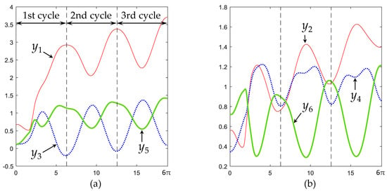
Figure 7.
(a,b) Time evolution of when tracking the trajectory of Equation (22) with k = 0.01.
To better illustrate this noncyclic trajectory, Figure 8 presents a sequence of snapshots of the manipulator as its inputs traverse the trajectories graphed in Figure 7. Only the first two cycles are presented in Figure 8. Supplementary video S2 attached displays the animation of these two cycles, as well as a third cycle.
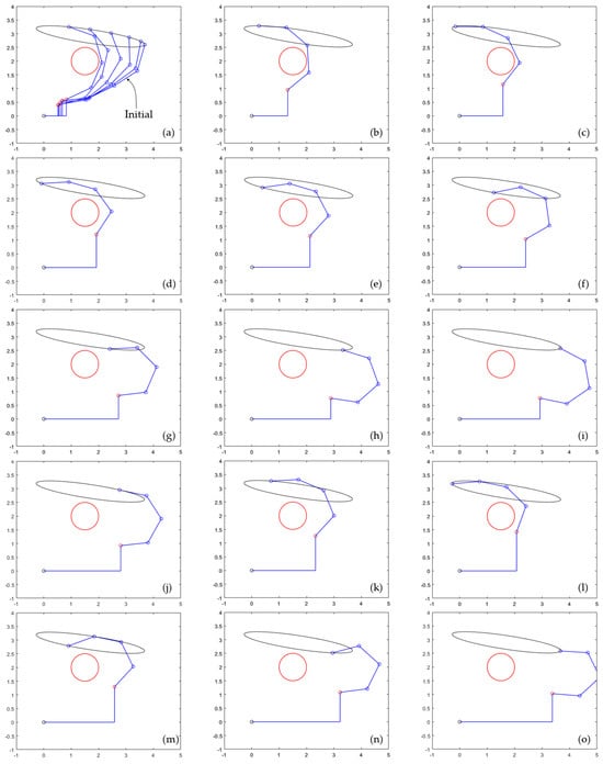
Figure 8.
(a–i) Execution of the first cycle of the desired output trajectory given by Equation (22), for k = 0.01. (j–o) Execution of the second cycle. Supplementary video S2 attached shows this figure in motion, including a third cycle that is different from the previous two cycles.
Figure 8a–i show execution of the first cycle. In Figure 8a, the manipulator is approaching the obstacle. Between Figure 8b,e, the gradient term of Equation (10) acts to avoid the obstacle. Between Figure 8f,i, the links of the manipulator are sufficiently far from the obstacle, and the cost f of Equation (11) is negligible (with negligible derivative), so the corrective term of Equation (10) does not have significant effect. Figure 8i shows the configuration of the manipulator at the end of the first cycle of the elliptic trajectory, which does not coincide with the initial configuration shown in Figure 8a.
Figure 8j–o show a sequence of snapshots of the configuration of the manipulator during execution of the second cycle, completing the second cycle in Figure 8o. When comparing these snapshots to those of the first cycle, one observes the noncyclicity of the input trajectory, where the manipulator is further away from the obstacle than in Figure 8a,i. A third cycle can be observed in attached video S2, which ends with the manipulator even further away from the obstacle.
As this example shows, generalized-inverse-velocity-based kinematic control can be used for obstacle avoidance, but its performance is not easy to tune or predict. For this example, a time step of seconds was sufficient to achieve obstacle avoidance for different values of k, and it was possible to avoid obstacles without excessively conservative distances between links and obstacles by choosing a small value of k = 0.01. However, this worked well only for the first cycle. After completing the first cycle, due to the nonholonomic nature of Equation (9), the manipulator drifts and executes subsequent cycles far from the obstacle, where of Equation (10) becomes negligible, yielding postures similar to those that would have been adopted if the first cycle had been executed using a larger value of k, as demonstrated in Figure 6. This suggests that the choice of parameters k and (which have been kept constant throughout this example) may actually be rather arbitrary, because nonholonomy may end up wasting or undoing a careful choice of such parameters. This is even more important in difficult scenarios such as the one treated in Section 4.2.3, where a highly redundant manipulator must avoid several obstacles, and choice of parameters k and is critical for performance of generalized-inverse-velocity-based kinematic control.
4.2. Twenty-Degree-of-Redundancy Trajectory Tracking and Obstacle Avoidance
4.2.1. A Twenty-Degree-of-Redundancy Manipulator
Consider a highly redundant variant of the manipulator of Figure 1 that is shown in Figure 9. Instead of having four links with relative angles … , it has 21 links with relative angles … , where all links have unit length.
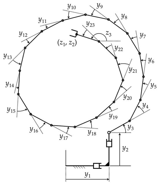
Figure 9.
A manipulator with r = 20 degrees of redundancy.
The initial configuration of the manipulator is shown in Figure 10, given by the following input angles.
This manipulator has n = 23 degrees of freedom. Outputs of the manipulator are the position coordinates of the outboard end of the last link and its orientation, i.e.,
Since there are m = 3 outputs, the degree of redundancy is r = n m = 23 3 = 20, so this can be considered a hyper-redundant manipulator.
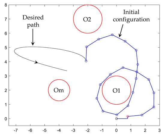
Figure 10.
Obstacles and manipulator initial configuration.
The task of this manipulator is to follow the output trajectory
which means that the outboard endpoint of the manipulator must describe the desired path given by the first two coordinates of Equation (25), and the last link maintains a constant orientation given by the last coordinate of Equation (25). The desired path is displayed in Figure 10. The desired trajectory must be achieved from t = 0 to t = 1.2, while the manipulator avoids three circular obstacles that are shown in Figure 10. Two obstacles are stationary, labeled O1 and O2 in Figure 10, where O1 is a circle centered at (0, 2) with unit radius, and O2 is another circle of unit radius centered at (−2, 7). Note that, initially, the manipulator wraps around obstacle O1. There is a third circular obstacle labeled Om in Figure 10 with radius 0.75 that is mobile. Its center starts at (−4, 2) and translates with constant speed until reaching the point (−3, 5.5) at t = 1, remaining static at that point for t > 1.
4.2.2. Differentiable-Manifold Output Tracking and Obstacle Avoidance
The path-planning obstacle avoidance problem is first treated using the differentiable manifold algorithm of Section 3.3 with a time step of s, which results in the sequence of postures shown in Figure 11 (supplementary video S3 is attached that illustrates the continuous motion). As demonstrated by Figure 11, the algorithm is able to resolve redundancy and obtain a feasible motion that tracks the desired output trajectory of Equation (25), while avoiding penetration of all obstacles for all time. First, the manipulator contacts obstacle O1 (Figure 11b), and then it contacts obstacle O2 (Figure 11c–d), to lose contact later (Figure 11e–h). In Figure 11i, the manipulator contacts the mobile obstacle Om and subsequently adjusts its configuration continuously to avoid penetrating this mobile obstacle as it approaches stationary obstacle O2 (Figure 11i–l). A difficult situation occurs, as shown in Figure 11m, when the mobile obstacle Om stops close to obstacle O2, after which Om and O2 create a narrow corridor through which the manipulator must maneuver (see the magnified view of the corridor in the inset of Figure 11m). The differentiable manifold algorithm of Section 3.3 is able to handle this situation seamlessly. It completes the desired trajectory, as demonstrated in Figure 11m–o.
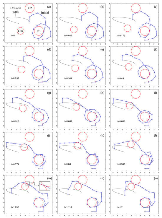
Figure 11.
(a–o) Successful redundancy resolution in a highly redundant manipulator with obstacle avoidance, using the differentiable manifold algorithm of Section 3.3. Supplementary video S3 of this sequence is attached.
4.2.3. Generalized-Inverse-Velocity Output Tracking and Obstacle Avoidance
The problem treated in Section 4.2.2 is attempted using the generalized inverse velocity method, numerically integrating Equation (9) with the term of Equation (10) to avoid obstacles. For this method, it is necessary to select two parameters, the time step used to numerically integrate Equation (9) (using again the fourth-order Runge–Kutta method) and the coefficient k used in Equation (10) to tune the rate of minimization of the cost function that penalizes proximity to obstacles. For a less complex example such as the one studied in Section 4.1.2, these two parameters were successfully set. However, for this more complex example with three obstacles (one of them mobile) and, more importantly, a narrow corridor such as the one shown in Figure 11m, the choice of parameters becomes critical. A smaller time step allows accurate numerical integration and smooth motions, but the simulation takes more CPU time to complete the full trajectory (or, in case the method is used to update the configuration in a real-time controller, it requires a more demanding controller that is able to operate at smaller sample times ). A smaller k performs the minimization of the cost function more slowly, which yields smoother motions that come closer to obstacles. However, a small value of k requires using a very small time step to enable the algorithm to avoid penetrating obstacles.
Table 1 shows 16 combinations of (k, ) and the result of obstacle avoidance for each combination. The result of each combination is represented by a grade F, D, or C, with the following meaning:

Table 1.
Results of the generalized inverse velocity method for different pairs .
- Grade F means that the simulation fails when the first obstacles (O1 or O2) are contacted, long before the narrow corridor indicated in Figure 11m is formed. The failure consists in the manipulator suffering a discontinuity in its configuration upon contact.
- Grade D means that the simulation fails when the manipulator is trapped by the narrow corridor. The failure consists in the manipulator suffering a discontinuity in its configuration when the corridor is formed, without penetrating obstacles.
- Grade C means that, when the narrow corridor is formed, the manipulator starts to penetrate obstacles and suffers discontinuous jumps in its configuration.
The lower-right case of Table 1 (k = 0.0001 and ) is illustrated in Figure 12. This case has been chosen for illustration because, despite not being fully successful (in fact, no case of Table 1 is fully successful), it exhibits the most similar behavior to Figure 11. It should be noted that the result of Figure 12 required a very slow simulation, due to the small time step of 0.00001 s, in contrast to the simulation of Figure 11 that worked well with a time step of 0.001 s. As Figure 12 shows, the generalized-inverse-velocity-based method yields a solution that is not very different from the one shown in Figure 11 during the beginning of the trajectory. The links contact obstacles and wrap around them as the manipulator progresses, including the mobile obstacle Om. The problem occurs when the mobile obstacle forms the narrow corridor with static obstacle O2. In that case, as Figure 12m shows, the manipulator starts to penetrate obstacles. It also suffers discontinuities in its configuration that occur between Figure 12l and m. This behavior can be better observed in supplementary video S4 attached. In any case, the trajectory becomes infeasible. In fact, according to Table 1, no valid combination of (k, ) was found that accomplishes this trajectory while avoiding obstacles with the generalized inverse velocity method. In contrast, the differentiable manifold method of Section 3.3 was able to easily solve this problem, as demonstrated in Figure 11 and Supplementary video S3.
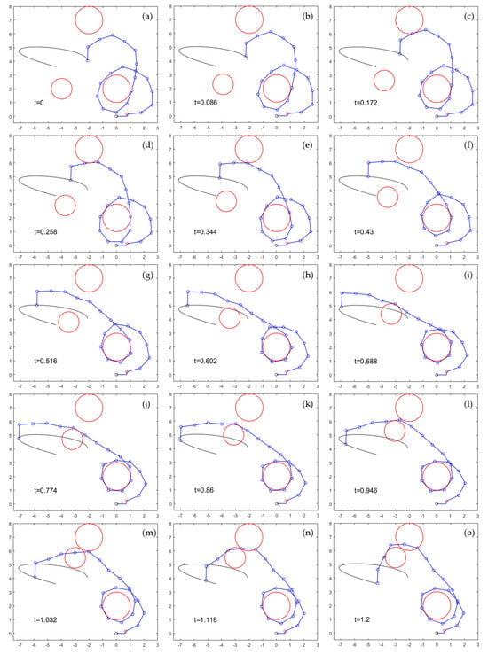
Figure 12.
(a–o) Unsuccessful redundancy resolution in a highly redundant manipulator with obstacle avoidance, using the generalized inverse velocity method of Equation (9). Supplementary video S4 of this sequence is attached.
5. Discussion
Kinematic control of redundant manipulators has traditionally been conducted at the velocity level, where a generalized inverse is used with the velocity equation of Equation (9) to obtain joint velocities in terms of the task (or output) velocities and arbitrary input velocities. Joint trajectories are then determined by numerical integration of . Obstacle avoidance is traditionally treated by performing self-motions that approximately minimize a cost function of Equation (11) that penalizes proximity to obstacles. As shown in Section 4.1.2, this approach leads to difficult-to-predict behavior, due to nonholonomy, as the manipulator performs quite different postures between cycles of specified output trajectories for the four-degree-of-redundancy manipulator, despite fine-tuning the parameters of the method (the rate of minimization of the cost function) to avoid obstacles during the first cycle. As shown in Section 4.2.3, regardless of the values of tunable parameters, the generalized inverse velocity approach encounters insurmountable difficulties for the twenty-degree-of-redundancy manipulator in a complicated situation such as a narrow corridor between obstacles, leading to infeasible trajectories that exhibit discontinuities or penetration of obstacles. These examples show that theoretical deficiencies of the generalized-inverse-velocity-based redundancy resolution method identified in Section 1.4 lead to severe problems in manipulator control applications.
An operational configuration space differentiable manifold formulation is presented for kinematic control of redundant manipulators during obstacle avoidance. In contrast with the traditional generalized-inverse-velocity-based approach, the differentiable manifold formulation resolves kinematic redundancy at the configuration level, constructing an inverse mapping that parameterizes input coordinates as functions of output coordinates and self-motion coordinates . This mapping is holonomic, locally cyclic, and can be used to generate global obstacle-free motion plans, as described in Section 3.3. The algorithm presented defines a gap function in the vicinity of every collision that is a function of self-motion coordinates . The algorithm actively adjusts self-motion coordinates to avoid penetration of obstacles, keeping non-negative by solving an under-constrained system of nonlinear equations. The example of Section 4.1.1 demonstrates the cyclicity and real-time capability of the algorithm with the four-degree-of-redundancy manipulator. The example of Section 4.2.2 demonstrates its ability to treat very restrictive obstacle situations with the twenty-degree-of-redundancy manipulator, negotiating a narrow corridor while accurately completing the desired task.
Although this paper has focused on redundant serial manipulators, the differentiable manifold formulation is presented for non-serial redundant manipulators in [3], which makes it possible to extend the algorithm presented to non-serial manipulators. Future applications of the formulation presented will not only consider control at the kinematics level but also control at the dynamics level [4], where accurate holonomic control of obstacle avoidance can be exploited for controlling contact forces between links and obstacles. Kinematic control applications involving constraints on velocities and accelerations can also be addressed.
Supplementary Materials
The following supporting information can be downloaded at: https://www.mdpi.com/article/10.3390/machines12010010/s1: Video S1: Figure 5.mp4 (video of Figure 5); Video S2: Figure 8.mp4 (video of Figure 8); Video S3: Figure 11.mp4 (video of Figure 11); Video S4: Figure 12.mp4 (video of Figure 12).
Author Contributions
Conceptualization, E.J.H.; methodology, E.J.H. and A.P.; software, A.P.; validation, E.J.H. and A.P.; data curation, A.P.; writing—original draft preparation, E.J.H.; writing, review and editing, E.J.H. and A.P.; visualization, A.P. All authors have read and agreed to the published version of the manuscript.
Funding
This research received no external funding.
Data Availability Statement
Data is contained within the article.
Conflicts of Interest
The authors declare no conflicts of interest.
References
- Pars, L.A. A Treatise on Analytical Dynamics, 1965; Reprint by Ox Bow Press: Woodbridge, UK, 1979. [Google Scholar]
- Robbin, J.W.; Salamon, D.A. Introduction to Differential Geometry; Springer: Berlin/Heidelberg, Germany, 2022. [Google Scholar]
- Haug, E.J.; Peidro, A. Redundant Manipulator Kinematics and Dynamics on Differentiable Manifolds. J. Comput. Nonlinear Dyn. 2022, 17, 111008. [Google Scholar] [CrossRef]
- Haug, E.J. Redundant Serial Manipulator Inverse Position Kinematics and Dynamics. J. Mech. Robot. 2024, 16, 081008. [Google Scholar] [CrossRef]
- Haack, W.; Wendland, W. Lectures on Partial and Pfaffian Differential Equations; Pergamon Press: Oxford, UK, 1972. [Google Scholar]
- Whitney, D.E. Resolved Motion Rate Control of Manipulators and Human Prostheses. IEEE Trans. Man-Mach. Systems. 1969, 10, 47–53. [Google Scholar] [CrossRef]
- Siciliano, B. Kinematic Control of Redundant Robot Manipulators: A Tutorial. J. Intell. Robot. Systems. 1990, 3, 201–212. [Google Scholar] [CrossRef]
- Chiaverini, S.; Oriolo, G.; Maciejewski, A.A. Springer Handbook of Robotics, 2nd ed.; Robots, R., Siciliano, B., Khatib, O., Eds.; Springer: Berlin/Heidelberg, Germany, 2016. [Google Scholar]
- Khatib, O. A Unified Approach for Motion and Force Control of Robot Manipulators: The Operational Space Formulation. IEEE J. Robot. Automation. 1987, RA-3, 43–53. [Google Scholar] [CrossRef]
- Khatib, O. The Operational Space Framework. JSME Int. J. Ser. C. 1993, 36, 277–287. [Google Scholar] [CrossRef]
- Klein, C.A.; Huang, C.-H. Review of Pseudoinverse Control for Use with Kinematically Redundant Manipulators. IEEE Trans. Syst. Man Cybern. 1983, SMC-13, 245–250. [Google Scholar] [CrossRef]
- De Luca, A.; Oriolo, G. Nonholonomic Behavior in Redundant Robots Under Kinematic Control. IEEE Trans. Robot. Autom. 1997, 13, 776–782. [Google Scholar] [CrossRef]
- Shamir, T.; Yomdin, Y. Repeatability of Redundant Manipulators: Mathematical Solution of the Problem. IEEE Trans. Autom. Control 1988, 33, 1004–1009. [Google Scholar] [CrossRef]
- Simas, H.; Di Gregorio, R. A Technique Based on Adaptive Extended Jacobians for Improving the Robustness of the Inverse Numerical Kinematics of Redundant Robots. J. Mech. Robot. 2010, 11, 020913. [Google Scholar] [CrossRef]
- Mussa-Ivaldi, F.A.; Hogan, N. Integrable Solutions of Kinematic Redundancy via Impedance Control. Int. J. Robot. Res. 1991, 10, 481–491. [Google Scholar] [CrossRef]
- Haug, E.J. A Cyclic Differentiable Manifold Representation of Redundant Manipulator Kinematics. J. Mech. Robot. 2024, 16, 061005. [Google Scholar] [CrossRef]
- Liegeois, A. Automatic supervisory control of the configuration and behavior of multibody mechanisms. IEEE Trans. Syst. Man Cybern. 1977, 7, 868–871. [Google Scholar]
- Lee, K.K.; Buss, M. Obstacle avoidance for redundant robots using Jacobian transpose method. In Proceedings of the 2007 IEEE/RSJ International Conference on Intelligent Robots and Systems, San Diego, CA, USA, 29 October–2 November 2007; pp. 3509–3514. [Google Scholar]
- Maciejewski, A.A.; Klein, C.A. Obstacle avoidance for kinematically redundant manipulators in dynamically varying environments. Int. J. Robot. Res. 1985, 4, 109–117. [Google Scholar] [CrossRef]
- Slotine, S.B.; Siciliano, B. A general framework for managing multiple tasks in highly redundant robotic systems. In Proceedings of the 5th International Conference on Advanced Robotics, Pisa, Italy, 19–22 June 1991; Volume 2, pp. 1211–1216. [Google Scholar]
- Flacco, F.; De Luca, A.; Khatib, O. Control of redundant robots under hard joint constraints: Saturation in the null space. IEEE Trans. Robot. 2015, 31, 637–654. [Google Scholar] [CrossRef]
- Flacco, F.; De Luca, A.; Khatib, O. Motion control of redundant robots under joint constraints: Saturation in the null space. In Proceedings of the 2012 IEEE International Conference on Robotics and Automation, Saint Paul, MN, USA, 14–18 May 2012; pp. 285–292. [Google Scholar]
- Kazemipour, A.; Khatib, M.; Al Khudir, K.; Gaz, C.; De Luca, A. Kinematic control of redundant robots with online handling of variable generalized hard constraints. IEEE Robot. Autom. Lett. 2022, 7, 9279–9286. [Google Scholar] [CrossRef]
- Ziese, A.; Fiore, M.D.; Peters, J.; Zimmermann, U.E.; Adamy, J. Redundancy resolution under hard joint constraints: A generalized approach to rank updates. In Proceedings of the 2020 IEEE/RSJ International Conference on Intelligent Robots and Systems (IROS), Las Vegas, NV, USA, 24 October 2020–24 January 2021; pp. 7447–7453. [Google Scholar]
- Fiore, M.D.; Meli, G.; Ziese, A.; Siciliano, B.; Natale, C. A general framework for hierarchical redundancy resolution under arbitrary constraints. IEEE Trans. Robot. 2023, 39, 2468–2487. [Google Scholar] [CrossRef]
- Atkinson, K.E. An Introduction to Numerical Analysis, 2nd ed.; Wiley: New York, NY, USA, 1989. [Google Scholar]
- Corwin, L.J.; Szczarba, R.H. Multivariable Calculus; Marcel Dekker: New York, NY, USA, 1982. [Google Scholar]
- Haug, E.J. Computer-Aided Kinematics and Dynamics of Mechanical Systems, Volume II: Modern Methods, 3rd ed.; ResearchGate: Berlin, Germany, 2022; Available online: www.researchgate.net (accessed on 11 November 2023).
- Brogliato, B. Nonsmooth Mechanics—Models, Dynamics and Control, 3rd ed.; Springer International Publishing: Cham, Switzerland, 2016. [Google Scholar]
- Peidró, A.; Pérez-Navarro, P.D.; Puerto, R.; Payá, L.; Reinoso, O. Locking underactuated robots by shrinking their manifolds of free-swinging motion. Mech. Mach. Theory 2023, 188, 105403. [Google Scholar] [CrossRef]
Disclaimer/Publisher’s Note: The statements, opinions and data contained in all publications are solely those of the individual author(s) and contributor(s) and not of MDPI and/or the editor(s). MDPI and/or the editor(s) disclaim responsibility for any injury to people or property resulting from any ideas, methods, instructions or products referred to in the content. |
© 2023 by the authors. Licensee MDPI, Basel, Switzerland. This article is an open access article distributed under the terms and conditions of the Creative Commons Attribution (CC BY) license (https://creativecommons.org/licenses/by/4.0/).