Abstract
The teleoperation feature of a leader–follower robot is used to operate the robot in a working environment that is dangerous to the operator. This paper proposes a method for estimating the intended operation of the operator of the leader–follower robot and generating behaviors for the follower robot. By generating partially autonomous robot behavior, our proposed method decreases the burden on the operator and realizes a safe controller that is robust against misoperation or disturbances. Owing to the impact of misoperation on estimation and the potential for unintended movement of the follower robot, our proposed estimation method relies on historical values of intended operation. The proposed method was verified through simulation using real operation inputs to the leader system based on practical scenarios, including misoperation.
1. Introduction
Leader–follower robots, which are also known as master–slave robots, and their related technology, can be used in various areas, including rehabilitation or computer-assisted surgery [1,2,3,4,5]. When the circumstances and/or situation are unknown or complex, autonomous robots are not suitable because they are incapable of carrying out the corresponding advanced assessments according to the situation. However, a leader–follower robot is appropriate for work under unknown conditions because it is operated by a person who can adapt their decisions accordingly. The operation of the follower robot corresponds to input from the leader robot, which is a characteristic of leader–follower systems.
Many studies on leader–follower robots aim at achieving “human-machine integration” control [6,7,8,9,10,11,12,13,14]. This approach emphasizes mirroring human motion in robot actions, which enables precise control. However, in long-term work at an actual workplace, the following issues exist: (i) When performing remote operation, the operator must verify various sensor information to ensure safety. Although the operator can obtain many types of information in typical situations, limited information is provided to the operator by the leader system. The operator has to manipulate the follower robot based on this limited information, leading to an escalation in the information load that the operator needs to handle or speculate about. Consequently, this raises the overall burden on the operator during extended periods of work [15,16]. (ii) Under the influence of fatigue, it is hard for the operator to maintain the required posture or predetermined motion inside the cockpit of the leader system for a long time [16,17,18]. (iii) If the operator reacts to a disturbance in their immediate surroundings (including greetings from colleagues), because these reactions are unexpected, the follower robot’s behavior will deviate from the original intention, according to the characteristics of the leader–follower system [19]. (iv) Involuntary motions caused by the operator’s body (such as sneezing and wobbling) will also result in different follower robot behavior. When a follower robot does not behave as the operator intended, it may damage the surrounding environment [17,20].
Giving partial autonomy to the follower robot or switching autonomous operation modes is an effective solution for reducing the burden on the operator. When considering the degree of autonomy as shown in Figure 1, the degree of autonomy gradually proceeds from left to right, where direct operation is on the left and pure autonomous operation is on the right.
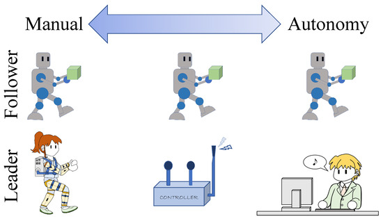
Figure 1.
Degrees of autonomy.
The explicit design of the controller in the middle position is desirable. This ensures that, when the system is operated according to the operator’s original intention, there is limited autonomy with bias toward the left side of the figure. Conversely, when the system is operated in a manner that deviates from the operator’s original intention, there is increased autonomy with bias toward the right of the figure. This design also solves a human interface design issue that occurs when the shapes and degrees of freedom of the leader system and follower robot, or those of the operator and follower robot, are different. However, few studies have addressed operation estimation in this context.
In this study, the term “original intention” refers to the operator’s initial assessment of the situation and intended actions to complete the assigned task based on real-time conditions. However, because of various reasons, the operator’s judgment may be compromised, and the operator may inadvertently carry out an unexpected operation, which is defined as misoperation.
Mghabghab et al. [21] employed a convolutional neural network to estimate the manipulating intention during drone operations, and used it to generate the drone’s motion. The teleoperated-autonomous shared control framework has been considered as a potential approach toward enhancing precision by changing the ratio between the master operation and autonomous motion [22]. By modifying the haptic assistance ratio, Corredor et al. [23] proposed an operation approach based on the operator’s intention. Among studies on the control of follower robots equipped with partial autonomy, Lee et al. [24] translated a single operating motion into each motion of several vehicle robots. Kawano et al. [25] controlled an underwater vehicle through autonomous control to maintain stable orientation regardless of the operator’s commands. These systems estimated the intention of motion directly, but did not estimate a higher-order intention such as behavior, which is more complex and strategic. Huang et al. [26] introduced a hierarchical-level intention tracking system aimed at mitigating collisions between collaborative robots and human operators during operational tasks and facilitating human intervention in the event of failures. However, within this framework, estimations of both high-level and low-level intentions are employed to deduce the selection of predetermined tasks. Bowman et al. [27] proposed a multi-task robot grasping model and an intent-uncertainty-aware grasp planner, which implemented complex operation intention estimation for generating robust grasp poses to reduce the operator’s workload, but this system lacks the response to misoperation. Other studies have attempted to model human decision-making procedures [28,29], but treated the estimation of future choices using game theory, which is different to estimating the current intention to perform a robot operation.
The objective of this study was not to aim for the high level of precision of remote robot control by integrating humans and machines, but to estimate the intended operation based on the operator’s original intention, and generate follower robot behaviors such that the follower robot behaves with partial autonomy. Thereby, this study aimed to decrease the burden on the operator and realize a safe controller that is robust against misoperation and disturbances. The main contribution of our proposed method is a solution to issues (iii) and (iv) mentioned above. Moreover, our proposed method also solves issues (i) and (ii).
In [30], the authors proposed a method for estimating and representing the operator’s intention based on the operation inputs and environmental information. However, because the method anticipates the intended operation at each sampling, misoperation still affects the estimation and makes the follower robot move in a way that the operator did not intend. In this paper, an estimation method using historical values of the intended operation is proposed. Our proposed method was verified by simulation using real operation inputs to the leader system under different practical scenarios, including misoperation.
2. Leader-Follower Robot
2.1. Outline of the Control System
The overall view of the controller in this study is shown in Figure 2. Direct operation, as used in conventional teleoperated robots, calculates the desired travel distance and velocity according to the sensor values measured at the leader and follower, and then controls the follower robot. In this study, the element of operation and the element of movement do not simply correspond. In other words, there is no direct correspondence between the force sensor and the arm operation, or between the leg-tracking camera and the locomotive unit. Instead, the intention estimator determines the operation intention and the motion generator uses the results of the operation intention estimated and the values of each sensor to determine the speed and the amount of movement. However, in this paper, the details of the motion generator are omitted because this paper focuses on the overall view of the controller and the processing in the intention estimator.
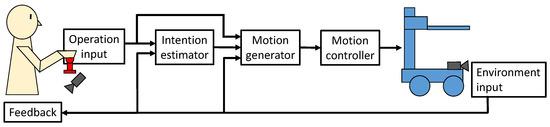
Figure 2.
Outline of proposed control system.
2.2. Leader System and Follower Robot
A leader–follower robot that can lift an object, transport it, and lower it was considered. To verify the proposed control system, the leader system is shown in Figure 3. Figure 4 shows the follower robot, whose specifications are listed in Table 1.
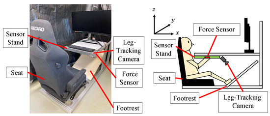
Figure 3.
Leader system.
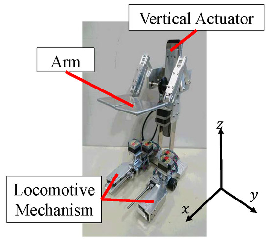
Figure 4.
Follower robot.

Table 1.
Specifications of follower robot.
The leader system consists of an aluminum frame, and is equipped with a six-degrees-of-freedom force sensor (FFS055YA501, Leptrino Inc., Nagano, Japan) and web camera (CMS-V31SETBK, Sanwa Supply Inc., Okayama, Japan). Additionally, to create an environment that is not prone to fatigue, the leader system is equipped with a car seat suitable for long-distance driving (SR-7F KK100, Recaro Inc., Shiga, Japan). The operator sits on the chair at the center of this system and operates the robot by applying force using a grip attached to the force sensor. The camera detects the foot movement, which is used as input to operate the robot.
The follower robot consists of an arm unit to lift an object, a lift unit to move the arm horizontally and vertically, and a locomotion unit. A linear actuator (SKR2602AE, THK Co., Ltd., Tokyo, Japan) moves the arm vertically. A stepper motor (PKP243D15A, Oriental Motor Co., Ltd., Tokyo, Japan) extends the arm by 7 mm, as shown in Figure 5 and Figure 6. Two driving wheels are arranged on the opposing sides of the locomotion unit and connected to stepper motors (PKP233D15A, Oriental Motor Co., Ltd.). Additionally, outriggers are attached in front of the locomotive unit to prevent overturning when the robot transports heavy objects [31], and stepper motors (PKP233D15A and PKP213D05A, Oriental Motor Co., Ltd.) are used to drive them. To prevent the follower robot from colliding with obstacles such as pedestrians and walls, the locomotive unit is equipped with distance sensors (VL53L0X, Strawberry Linux Co., Ltd., Tokyo, Japan) on all sides.
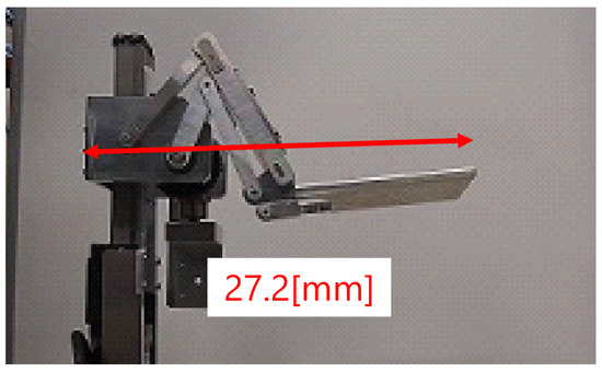
Figure 5.
Distance of arm (flexion).
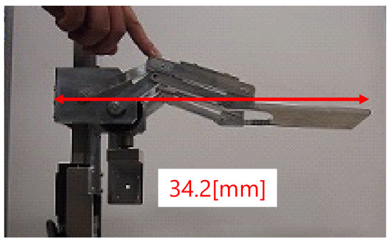
Figure 6.
Distance of arm (extension).
2.3. Controller Hardware
Figure 7 shows an outline of the controller hardware. The left part of Figure 7 corresponds to the right part of Figure 3, the “Force Sensor” and the “Camera” in this figure constitute the “Operation input” unit in Figure 2, and “Leader PC” in this figure is responsible for the data collection of the “Operation input” unit and the calculation of the “Intention estimator” unit in Figure 2. The right part of Figure 7 corresponds to the follower robot in Figure 2 and Figure 4. The computer (PC) of the leader system obtains the operation inputs from the force sensor and the web camera, and sends them to the follower robot. Basic arm control is performed according to the force direction and magnitude. The details of the control method are provided in the following section. Locomotion control is based on the measured force and step length, and the step length is detected using a simple method, as follows. A colored marker with a diameter of approximately 30 mm is attached to each toe as shown in Figure 8. The web camera images are transformed such that the marker pixels are white and the background pixels are black. The distance between each detected marker center is used as the step length.
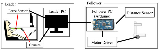
Figure 7.
System configuration.
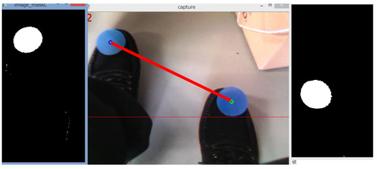
Figure 8.
Step length calculation. The center frame shows the movement of the operator’s feet. The left and right frames show the result of the image processing of the logos on the operator’s feet which will be used to calculate the step length. The red line in the center frame means the step length.
The follower robot is equipped with a microcomputer (Arduino Mega 2560 R3, Arduino, Monza e della Brianza, Italy) for the motor drivers and a distance sensor from which the relative distance and velocity of the obstacle are calculated as environmental inputs. The desired motion values are generated by the microcomputer using the operation inputs sent from the leader and the environmental inputs. Serial communication is used between the leader and the follower. The desired values of the generated motion are sent to the motor controllers. Each stepper motor has a motor driver (L6470, Strawberry Linux Co., Ltd.), and the linear actuator has a servo driver (TLC-005-024DC, THK Co., Ltd.).
3. Intention Estimator
3.1. Behavior Map [30]
A behavior-based tree is occasionally used to describe and design the actions of non-player characters in video games [32]. In contrast to a state-based tree, actions can be described directly at the end of the behavior-based tree.
In this study, this idea was applied to create a “behavior map” to fit the potential actions of the follower robot with respect to the evaluation indices as its axes. As an example, the degrees of risk, movement (locomotive operation), and arm operation are selected as the evaluation indices and form the three axes of the behavior map, as shown in Figure 9. The degree of risk represents how dangerous it is to operate the follower robot. The reason why the degree of risk is proposed as an evaluation index is to reduce the overall burden on the operator during extended periods of work. The degree of risk is calculated based on the relative distance and relative velocity between the follower robot and the obstacle measured by distance sensors. By analyzing the value of the degree of risk, it can be judged whether the follower robot has the risk of colliding with the obstacle to ensure the safety of work. With this evaluation index, the operator does not need to constantly pay full attention to the distance sensor data, thereby reducing the overall burden on the operator during extended periods of work. Also, the degree of movement indicates whether the operator intends to perform a movement operation, and the degree of arm operation indicates whether the operator intends to operate the robot’s arm. Each evaluation index is obtained by simplified fuzzy inference, as explained in the next subsection. The three degrees are scalars ranging from −1 to 1, with the values going from negative to positive to indicate the risk intensity or the intention from weak to strong. The follower robot can perform five behaviors, as presented in Table 2. These actions are assigned to each quadrant of the behavior map to form the intended operations corresponding to the figure and table.
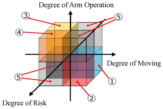
Figure 9.
Behavior map (refer to Table 2).
Table 2.
Behavior for each quadrant.
The behavior map is a method of expressing behavior. The values of the evaluation indices become the coordinates of a point, and the quadrant in which the point is located determines the intended operation.
3.2. Calculation of Indices
This study used simplified fuzzy inference to obtain the coordinate location on the behavior map from the input. The inputs provided by the leader system are the force in the x (forward and backward), y (right and left), and z (vertical) directions, and the step length. The inputs from the follower robot are the relative distance and velocity between the follower robot and an obstacle. The output represents a coordinate point on the behavior map. The degree of risk is determined from the relative distance and velocity with respect to an obstacle. The degree of movement is determined from the input force in the horizontal plane and the step length. The degree of arm operation is determined from the input force in the sagittal plane and the step length.
The antecedent membership functions corresponding to the relative distance, relative velocity, force, and step length are shown in Figure 10, Figure 11, Figure 12 and Figure 13. Figure 10 shows the membership functions for the relative distance as “VN (Very Near)”, “N (Near)”, “M (Medium)”, “F (Far)”, or “VF (Very Far)”. Figure 11 shows the membership functions for the relative velocity as “VSl (Very Slow)”, “Sl (Slow)”, “M (Medium)”, “F (Fast)”, or “VF (Very Fast)”. Figure 12 shows membership functions for the magnitude of the force in each direction (x-, y-, and z-axis in Figure 4) as “NB (Negative Big)”, “ZO (Zero)”, and “PB (Positive Big)”. Figure 13 shows the membership functions for the step length as “B (Big)” or “S (Small).”
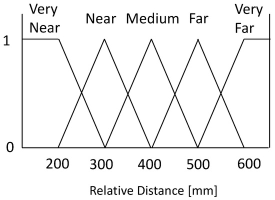
Figure 10.
Membership functions of relative distance.
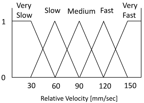
Figure 11.
Membership functions of relative velocity.
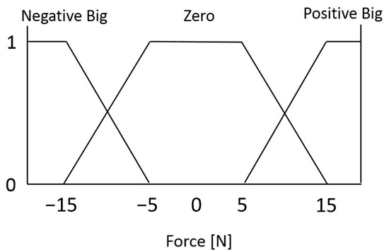
Figure 12.
Membership functions of force magnitude.
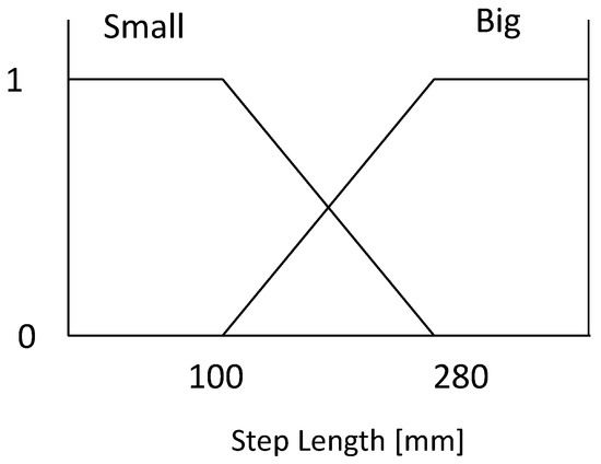
Figure 13.
Membership functions of step length.
The consequent membership functions are constants, as presented in Table 3, Table 4 and Table 5, and all consequent parts belong to the singleton type.
Table 3.
Fuzzy rules of the degree of risk.
Table 4.
Fuzzy rules of the degree of movement.
Table 5.
Fuzzy rules of the degree of arm operation.
Table 3 lists the fuzzy rules for the degree of risk: a negative value indicates a safe situation, while a positive value indicates a dangerous situation. Here, when the relative distance between the follower robot and an obstacle is “Very Near,” the values are positive because the follower robot has a high potential for collision regardless of the relative velocity.
Table 4 lists the fuzzy rules of the degree of movement; a negative value indicates that the operator does not want to move the follower robot, while a positive value indicates that the operator wants the follower robot to move. A large step length indicates the intention to move, while a small step indicates the intention to stop moving, as illustrated in Figure 13. Because, in a real transportation scenario, the operator will push the payload in the locomotion direction, the force values are also considered.
Table 5 lists the fuzzy rules of the degree of arm operation. A negative value means that the operator has no intention of manipulating the arm part. In contrast, a positive value indicates that the operator intends to manipulate the arm part of the follower robot. The direction and magnitude of the force are mainly related to the arm operation. Moreover, it is assumed that the arm operation is only performed when movement has stopped. Therefore, a large step length results in a negative degree of arm operation.
When is the compatibility determined from Figure 10, Figure 11, Figure 12 and Figure 13 and is the output from the consequent part, the value from each fuzzy rule, that is, the coordinates in behavior map , is calculated as (1).
where , A, and R indicate the degree of movement, arm operation, and risk, respectively.
4. Incorporating Historical Values of Operation Intention
The intention estimation uses current inputs. However, while there is no issue when the intention and action of the operator match, there may be trouble when there is a mismatch between the intention estimated based on the operator’s actions and the operator’s actual original intention. Notably, experienced operators will rarely perform unexpected motions intentionally during robot operation. Hence, in this study, the transition of the estimated intention is expressed and evaluated as a continuous function. When the operator behaves according to a specific intention, a sudden change in the estimated intention can be considered as unnatural, even if sudden and unexpected operational inputs cause this change. Thus, the continuousness of the estimated intention can suppress unexpected behavior caused by disturbances or abrupt action.
To suppress unexpected behavior, the evaluation indices estimated with current inputs are modified using the moving average of historical evaluation index values. The modified evaluation indices () are calculated as follows:
where is the correction gain and n is the number of historical values. In this study, the gain was empirically determined as follows: , , and .
5. Simulation Verification of Intention Estimator
5.1. Method
Three cases of the operator temporarily acting contrary to the original intended operation were considered. The estimated intended operation was drawn as a locus on the behavior map to compare the scenarios with and without historical values.
- (1)
- When the operator extends the robot arm to load an object, the operator takes a small step length to let the system determine that the robot arm is being operated, and apply force to the force sensor to perform the operation. If the operator’s foot slips suddenly during operation, this will increase the step length and cause the system to assess that the robot should be moving forward. After realizing that an unexpected operation has occurred, the operator will move their foot to the initial position and then input a command to operate the arm again. This scenario is consistent with issue (iv) mentioned in the Introduction. The operator’s foot may also slip owing to an external disturbance, such as being greeted by colleagues; therefore, this scenario is also consistent with issue (iii) mentioned in the Introduction.
- (2)
- When the operator moves the robot forward, the operator takes a larger step length to indicate to the system that the robot should be moving forward, and applies force to the force sensor to perform the operation. Additionally, the operator may become tired of maintaining the same posture during the operation and close their legs, which makes the step length smaller, indicating to the system that the robot arm should extend. After realizing that unexpected operation has occurred, the operator opens their legs; thus, the operation input returns to a movement command. This scenario is consistent with issue (ii) mentioned in the Introduction.
- (3)
- During the transport of an object, the operator commands the follower robot to move forward, even though an obstacle exists in front of it. This scenario is consistent with issue (i) mentioned in the Introduction.
In this study, the leader system was operated according to each considered scenario, and the schematic of the operator during operation is shown on the right part of Figure 3. The operation values were recorded every 0.2 s throughout the sampling period. The past 30 measurements were used to average the evaluation indices, and each misoperation was performed for 1 s.
To visualize the results, the estimated intentions are expressed on a plane of the behavior map, and are mapped to two dimensions. This is equivalent to omitting an axis in the behavior map in certain cases. In scenarios 1 and 2, the degree of risk is omitted because the working environments of these scenarios are assumed to be safe for arm operation. Therefore, the degrees of movement and arm operation are used as the axes. In scenario 3, because the operation of the robot arm is not involved, the degrees of movement and risk are used as the axes.
5.2. Scenario 1
While the original intended operation was ”Operate arm”, the actual operation inputs were “Stop”, “Operate arm”, “Move”, and “Operate arm”, in this order. The locus of intention estimated without the historical values is shown in Figure 14, and that estimated with the historical values is shown in Figure 15. The second and fourth quadrants indicate “Operate arm” and “Move” in the behavior map, respectively. The first and the third quadrants indicate “Stop”.
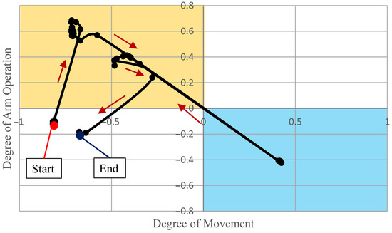
Figure 14.
Operating intention without historical values (Scenario 1).
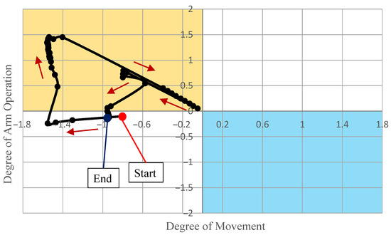
Figure 15.
Operating intention with historical values (Scenario 1).
As shown in Figure 14, the estimated intention changed from arm operation to locomotion, according to the input change. Therefore, generating motion and controlling the follower robot without historical intention values will result in collision with the surroundings, because the robot begins locomotion at the moment when the operator’s input changes.
In contrast, Figure 15 shows that the estimated intention did not enter the “Move” quadrant, even when the input changed from arm operation to locomotion. Therefore, the intention estimation was modified by the historical intention values. Thus, the safety of the robot and surroundings is retained even when misoperation occurs.
5.3. Scenario 2
While the original intended operation was ”Move”, the actual operation input was “Stop”, “Move”, “Operate arm”, and “Move”, in this order. The locus of intention estimated without the historical values is shown in Figure 16, and that estimated with the historical values is shown in Figure 17. The second and fourth quadrants indicate “Operate arm” and “Move” in the behavior map, respectively. The first and third quadrants indicate “Stop”.
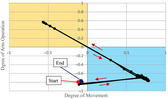
Figure 16.
Operating intention without historical values (Scenario 2).
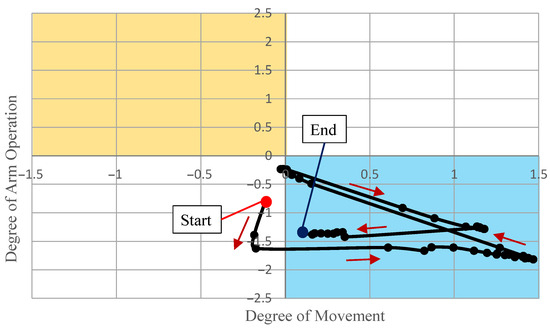
Figure 17.
Operating intention with historical values (Scenario 2).
As shown in Figure 16, the estimated intention changed from locomotion to arm operation, according to the change of input. Therefore, generating motion and controlling the follower robot without intention logs will cause the robot arm to collide with the objects in front of it, because the robot extends its arm at the moment when the operator’s input changes.
In contrast, Figure 17 shows that the estimated intention did not enter the “Operate arm” quadrant, even when the input changed from locomotion to arm operation. Therefore, the intention estimation was modified by the historical intention values.
5.4. Scenario 3
While the original intended operation was “Move”, the operation input continued to cause the follower robot to move forward although an obstacle existed in front of it. The locus of intention estimated without the historical values is shown in Figure 18, and that estimated with the historical values is shown in Figure 19. The first quadrant and second quadrant indicate “Avoid during movement”, and “Move” in the behavior map, respectively. The third and fourth quadrants indicate “Stop”.
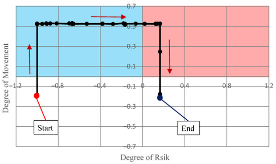
Figure 18.
Operating intention without historical values (Scenario 3).
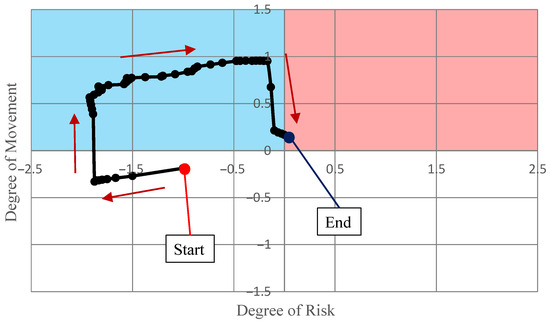
Figure 19.
Operating intention with historical values (Scenario 3).
As shown in Figure 18, the estimated intention locus entered the “Move” quadrant first, which matches the original intention. However, when the robot approached the obstacle, the operating intention changed to “Avoid during movement”. This means that the system cannot estimate the operator’s original intention.
In contrast, when using historical values, Figure 19 indicates that the estimated intention locus remained in the “Move” quadrant, even though the robot was relatively close to the obstacle.
However, the estimated intention moved into the “Avoid during movement” quadrant after the follower robot approached the obstacle. This may cause a collision with the obstacle if the obstacle moves toward the follower robot or a sudden disturbance in the load affects the follower robot’s motion. Therefore, the current evaluation indices for the degree of risk are more important than expected, and a smaller gain in calculating the degree of risk is better for the safe operation of the follower robot.
6. Conclusions
This paper presents a framework for estimating the operating intention for a leader–follower robot. In situations where leader–follower robots are used for disaster rescue and surgery, extended periods of work are unavoidable, and the burden placed on the operator or physician may induce misoperation, resulting in operation failure or unnecessary injury to the patient. The method proposed in this study aims to suppress misoperations at a high level such as intention estimation, thereby ensuring the safety of work and surgery. Consequently, we proposed the idea of Figure 1 to classify the degree of automation in this control system to handle situations of misoperations. In Figure 1, from direct operation on the left to pure autonomous operation on the right, the degree of automation gradually proceeds. In the case of non-misoperation, it is biased towards direct operation, but in the case of misoperation, it is biased towards pure autonomous operation, therefore it is called “partially autonomous”.
In order to realize the control system mentioned above, in this study, the operation intention estimator, which is composed of simplified fuzzy inference and a behavior map, was being used. Simplified fuzzy inference was used to estimate the operator’s original intention from the operation inputs and environmental information. The proposed behavior map can express the intended operation. The modification of the intended operation using historical values of intended operation forces the behavior to follow the original intended operation, even when the operator acts unexpectedly. Therefore, even if temporary misoperation occurs, the follower robot does not act according to the deviated intended operation, but maintains safe operation motion.
This study presents two main contributions:
- The framework proposed in this study aims to estimate more complex and strategic higher-order intention such as behavior, and suppress the impact on the estimated intention when misoperation occurs due to fatigue or external interference to the operator, to allow the movement to continue as expected. This is not possible with the method that aims for high precision control by direct estimation of the motion.
- The framework proposed in this study excels in the estimation of more generalized behaviors, making it particularly well-suited for leader–follower robots navigating uncertain work processes and undertaking tasks characterized by a heightened degree of flexibility. In contrast, existing methods facilitating the estimation of higher-order intentions do not sufficiently cater to the operational capabilities unique to leader–follower robots.
The limitations of this study are as follows: For the degree of risk and other evaluation indices reflecting the operation intention, heuristically-determined gains can be used to modify the values. However, a method for designing the gain according to each feature does not exist. For the evaluation of our proposed method in this study, the detection of misoperation or disturbances is also necessary. Additionally, the generation of target motion values for the estimated intended operation and other parts is also required to perform the entire control system. The above-mentioned issues should be addressed in future work.
Author Contributions
Conceptualization, Z.L., K.K. and K.N. (Katsuki Nagahara); methodology, all authors; system design, Z.L. and K.K.; software, K.N. (Katsuki Nagahara), K.K. and Z.L.; validation, all authors; formal analysis, K.N. (Katsuki Nagahara), K.K. and Z.L.; investigation, Z.L., K.N. (Katsuki Nagahara) and K.K.; resources, K.K.; data curation, K.N. (Katsuki Nagahara), K.K. and Z.L.; writing—original draft preparation, Z.L. and K.K.; writing—review and editing, all authors; visualization, K.K., K.N. (Katsuki Nagahara) and Z.L.; supervision, K.K.; project administration, K.K.; funding acquisition, K.K. All authors have read and agreed to the published version of the manuscript.
Funding
This research was funded by The Fujikura Foundation Research Grant (No. 14-025).
Data Availability Statement
The original data contributions presented in the study are included in the article; further inquiries can be directed to the corresponding authors.
Acknowledgments
We thank Edanz for editing a draft of this manuscript accessed on 1 January 2020.
Conflicts of Interest
The funders had no role in the design of the study; in the collection, analyses, or interpretation of the data; in the writing of the manuscript; nor in the decision to publish the results.
References
- Stone, R.J. Haptic feedback: A brief history from telepresence to virtual reality. In International Workshop on Haptic Human-Computer Interaction; Springer: Berlin, Heidelberg, 2000; pp. 1–16. [Google Scholar]
- Shahbazi, M.; Atashzar, S.F.; Patel, R.V. A systematic review of multilateral teleoperation systems. IEEE Trans. Haptics 2018, 11, 338–356. [Google Scholar] [CrossRef] [PubMed]
- King, C.; Culjat, M.O.; Franco, M.L.; Bisley, J.W.; Dutson, E.; Grundfest, W.S. Optimization of a pneumatic balloon tactile display for robot-assisted surgery based on human perception. IEEE Trans. Biomed. Eng. 2008, 55, 2593–2600. [Google Scholar] [CrossRef] [PubMed]
- Li, C.; Li, J.; Inoue, Y.; Liu, T. Verification of additional merits of a bimanual-coordinated rehabilitation robot using near-infrared spectroscopic technology. Adv. Robot. 2014, 28, 955–965. [Google Scholar] [CrossRef]
- Yokokohji, Y. The Use of Robots to Respond to Nuclear Accidents: Applying the Lessons of the Past to the Fukushima Daiichi Nuclear Power Station. Annu. Rev. Control. Robot. Auton. Syst. 2021, 4, 681–710. [Google Scholar] [CrossRef]
- Yokokohji, Y.; Yoshikawa, T. Bilateral control of master-slave manipulators for ideal kinesthetic coupling-formulation and experiment. IEEE Trans. Robot. Autom. 1994, 10, 605–620. [Google Scholar] [CrossRef]
- Khurshid, R.P.; Fitter, N.T.; Fedalei, E.A.; Kuchenbecker, K.J. Effects of grip-force, contact, and acceleration feedback on a teleoperated pick-and-place task. IEEE Trans. Haptics 2017, 10, 40–53. [Google Scholar] [CrossRef]
- Liu, M.; Meng, F.; Liang, Y. Generalized Pose Decoupled Network for Unsupervised 3D Skeleton Sequence-Based Action Representation Learning. Cyborg Bionic Syst. 2022, 2022, 0002. [Google Scholar] [CrossRef]
- Xu, D.; Wang, Q. Noninvasive Human-Prosthesis Interfaces for Locomotion Intent Recognition: A Review. Cyborg Bionic Syst. 2021, 2021, 9863761. [Google Scholar] [CrossRef]
- Wang, L.; Ma, L.; Yang, J.; Wu, J. Human Somatosensory Processing and Artificial Somatosensation. Cyborg Bionic Syst. 2021, 2021, 9843259. [Google Scholar] [CrossRef]
- Ding, R.; Cheng, M.; Han, Z.; Wang, F.; Xu, B. Human-machine interface for a master-slave hydraulic manipulator with vision enhancement and auditory feedback. Autom. Constr. 2022, 136, 104145. [Google Scholar] [CrossRef]
- Young, S.N.; Peschel, J.M. Review of Human–Machine Interfaces for Small Unmanned Systems With Robotic Manipulators. IEEE Trans. -Hum.-Mach. Syst. 2020, 50, 131–143. [Google Scholar] [CrossRef]
- Zhao, Y.; Xing, H.; Guo, S.; Wang, Y.; Cui, J.; Ma, Y.; Liu, Y.; Liu, X.; Feng, J.; Li, Y. A novel noncontact detection method of surgeon’s operation for a master-slave endovascular surgery robot. Med. Biol. Eng. Comput. 2020, 58, 871–885. [Google Scholar] [CrossRef] [PubMed]
- Okada, M.; Iwano, K. Human interface design for semi-autonomous control of leader-follower excavator based on variable admittance and stagnation/trajectory bifurcation of nonlinear dynamics. Mech. Eng. J. 2021, 8, 21-00127. [Google Scholar] [CrossRef]
- Shao, S.; Zhou, Q.; Liu, Z. Mental workload characteristics of manipulator teleoperators with different spatial cognitive abilities. Int. J. Adv. Robot. Syst. 2019, 16, 172988141988804. [Google Scholar] [CrossRef]
- Mizuno, N.; Tazaki, Y.; Hashimoto, T.; Yokokohji, Y. A comparative study of manipulator teleoperation methods for debris retrieval phase in nuclear power plant decommissioning. Adv. Robot. 2023, 37, 541–559. [Google Scholar] [CrossRef]
- Wakabayashi, S.; Magruder, D.F.; Bluethmann, W. Test of Operator Endurance in the Teleoperation of an Anthropomorphic Hand. In Proceedings of the 7th International Symposium on Artificial Intelligence, Robotics and Automation in Space: i-SAIRAS 2003, Nara, Japan, 19–23 May 2003. [Google Scholar]
- Danion, F.; Latash, M.L.; Li, Z.M.; Zatsiorsky, V.M. The effect of fatigue on multifinger co-ordination in force production tasks in humans. J. Physiol. 2000, 523 Pt 2, 523–532. [Google Scholar] [CrossRef]
- Regan, M.A.; Hallett, C.; Gordon, C.P. Driver distraction and driver inattention: Definition, relationship and taxonom. Accid. Anal. Prev. 2011, 43, 1771–1781. [Google Scholar] [CrossRef]
- Sun, Z.; Guo, J.; Guo, S.; Song, Y. Study on A Novel Strategy for Eliminating Tremor in Vascular Interventional Robot. In Proceedings of the 2022 IEEE International Conference on Mechatronics and Automation, Guilin, China, 7–9 August 2022; pp. 1263–1268. [Google Scholar]
- Mghabghab, S.; Elhajj, I.H.; Asmar, D. Personalized teleoperation via intention recognition. Adv. Robot. 2018, 32, 697–716. [Google Scholar] [CrossRef]
- Griffin, W.B.; Provancher, W.R.; Cutkosky, M.R. Feedback strategies for shared control in dexterous telemanipulation. In Proceedings of the 2003 IEEE/RSJ International Conference on Intelligent Robots and Systems, Las Vegas, NV, USA, 27–31 October 2003; Volume 3, pp. 2791–2796. [Google Scholar]
- Corredor, J.; Sofrony, J.; Peer, A. Decision-making model for adaptive impedance control of teleoperation systems. IEEE Trans. Haptics 2017, 10, 5–16. [Google Scholar] [CrossRef]
- Lee, D.; Spong, M.W. Bilateral teleoperation of multiple cooperative robots over delayed communication networks: Theory. In Proceedings of the 2005 IEEE International Conference on Robotics and Automation, Barcelona, Spain, 18–22 April 2005; pp. 360–365. [Google Scholar]
- Kawano, K.; Shimozawa, T.; Sagara, S. A master-slave control system for a semi-autonomous underwater vehicle-manipulator system. Artif. Life Robot. 2012, 16, 465–468. [Google Scholar] [CrossRef]
- Huang, Z.; Mun, Y.; Li, X.; Xie, Y.; Zhong, N.; Liang, W.; Geng, J.; Chen, T.; Katherine, D.C. Hierarchical Intention Tracking for Robust Human-Robot Collaboration in Industrial Assembly Tasks. In Proceedings of the 2023 IEEE International Conference on Robotics and Automation, London, UK, 29 May–2 June 2023; pp. 9821–9828. [Google Scholar]
- Bowman, M.; Li, S.; Zhang, X. Intent-Uncertainty-Aware Grasp Planning for Robust Robot Assistance in Telemanipulation. In Proceedings of the 2019 International Conference on Robotics and Automation, Montreal, QC, Canada, 20–24 May 2019; pp. 409–415. [Google Scholar]
- Egelman, D.M.; Person, C.; Montague, P.R. A computational role for dopamine delivery in human decision-making. J. Cogn. Neurosci. 1998, 10, 623–630. [Google Scholar] [CrossRef] [PubMed]
- Woodruff, C.; Vu, L.; Morgansen, K.A.; Tomlin, D. Deterministic modeling and evaluation of decision-making dynamics in sequential two-alternative forced choice tasks. Proc. IEEE 2011, 100, 734–750. [Google Scholar] [CrossRef]
- Nagahara, K.; Koyanagi, K.; Tamamoto, T.; Sawai, K.; Masuta, H.; Motoyoshi, T.; Oshima, T. Indirect estimation of operation intention using behavior map for master-slave robot systems. In Proceedings of the 2018 Joint 10th International Conference on Soft Computing and Intelligent Systems and 19th International Symposium on Advanced Intelligent Systems, Toyama City, Japan, 5–8 December 2018; pp. 1344–1347. [Google Scholar]
- Ishizaki, K.; Koyanagi, K.; Motoyoshi, T.; Masuta, H.; Oshima, T. Mechanics and structure for mobile power-assist equipment. In Proceedings of the 2014 IEEE/SICE International Symposium on System Integration, Tokyo, Japan, 13–15 December 2014; pp. 773–778. [Google Scholar]
- Khoo, A.; Dunham, G.; Trienens, N.; Sood, S. Efficient, Realistic NPC Control Systems using Behavior-Based Techniques. In Proceedings of the AAAI Spring Symposium on Artificial Intelligence and Interactive Entertainment II, Palo Alto, CA, USA, 25–27 March 2002; pp. 46–51. [Google Scholar]
Disclaimer/Publisher’s Note: The statements, opinions and data contained in all publications are solely those of the individual author(s) and contributor(s) and not of MDPI and/or the editor(s). MDPI and/or the editor(s) disclaim responsibility for any injury to people or property resulting from any ideas, methods, instructions or products referred to in the content. |
© 2023 by the authors. Licensee MDPI, Basel, Switzerland. This article is an open access article distributed under the terms and conditions of the Creative Commons Attribution (CC BY) license (https://creativecommons.org/licenses/by/4.0/).