
Application of TRIZ Innovation Method to In-Pipe Robot Design


Abstract
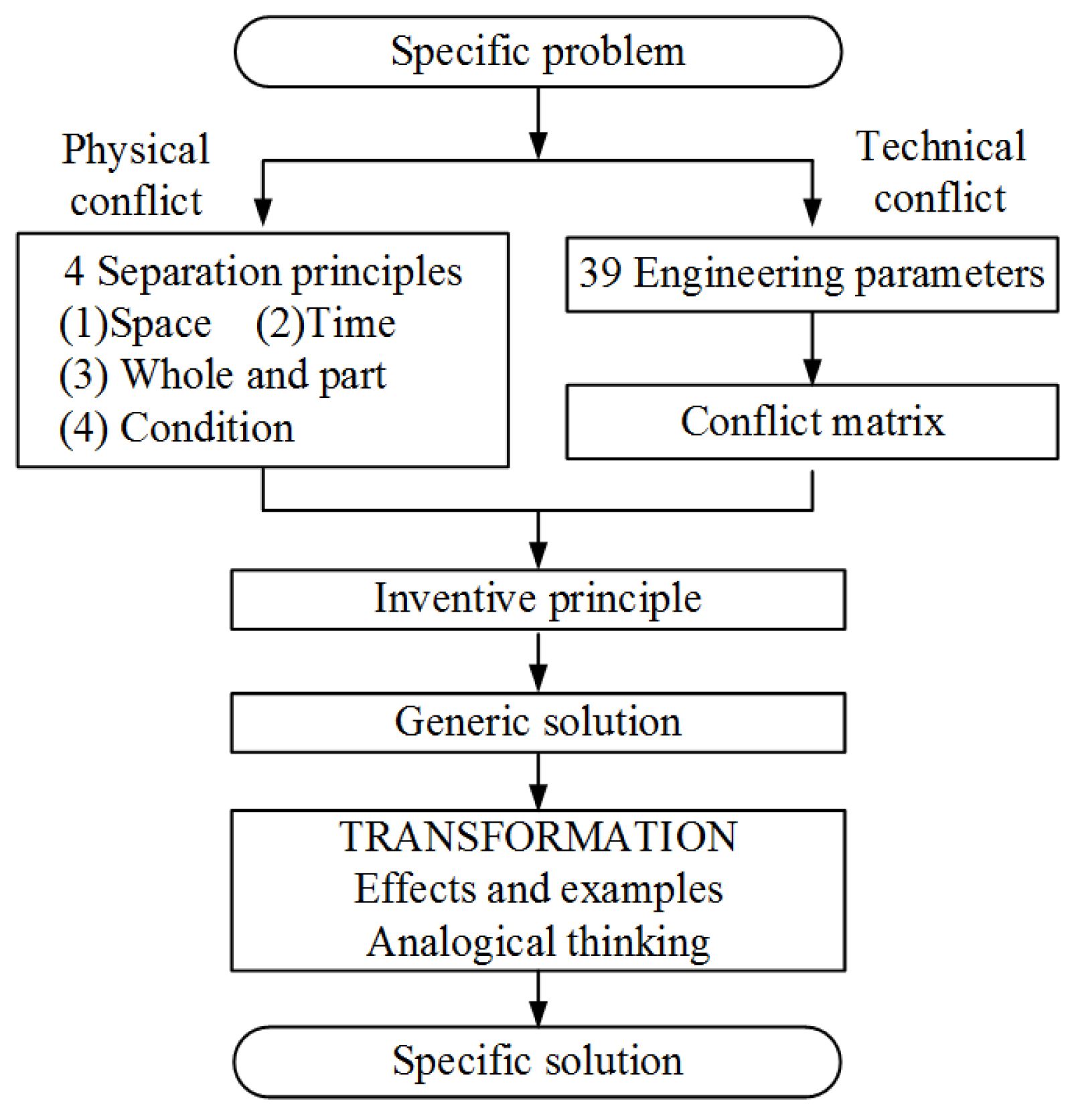
:1. Introduction
2. Explanation of the Novel Robot
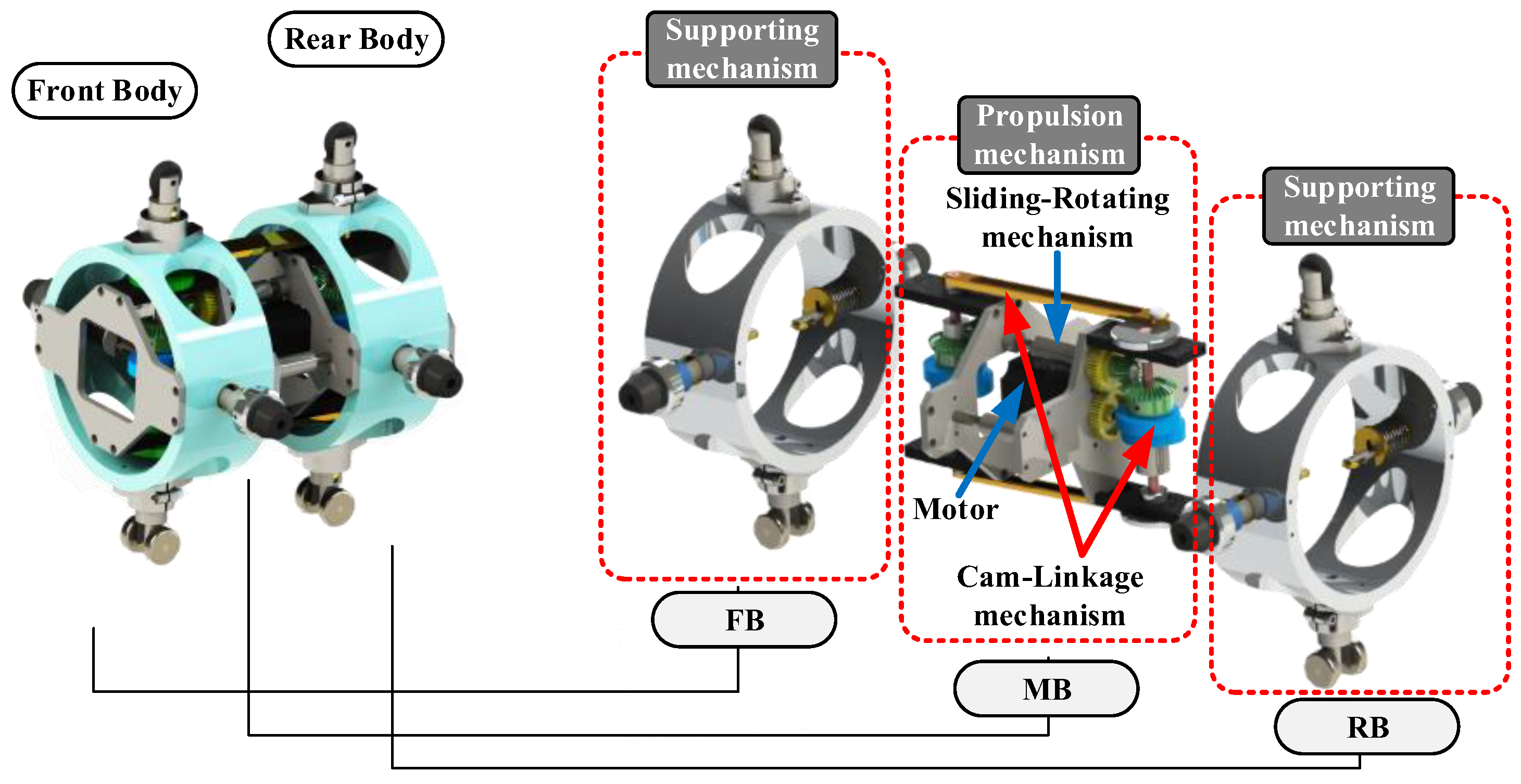
2.1. Overall Introduction
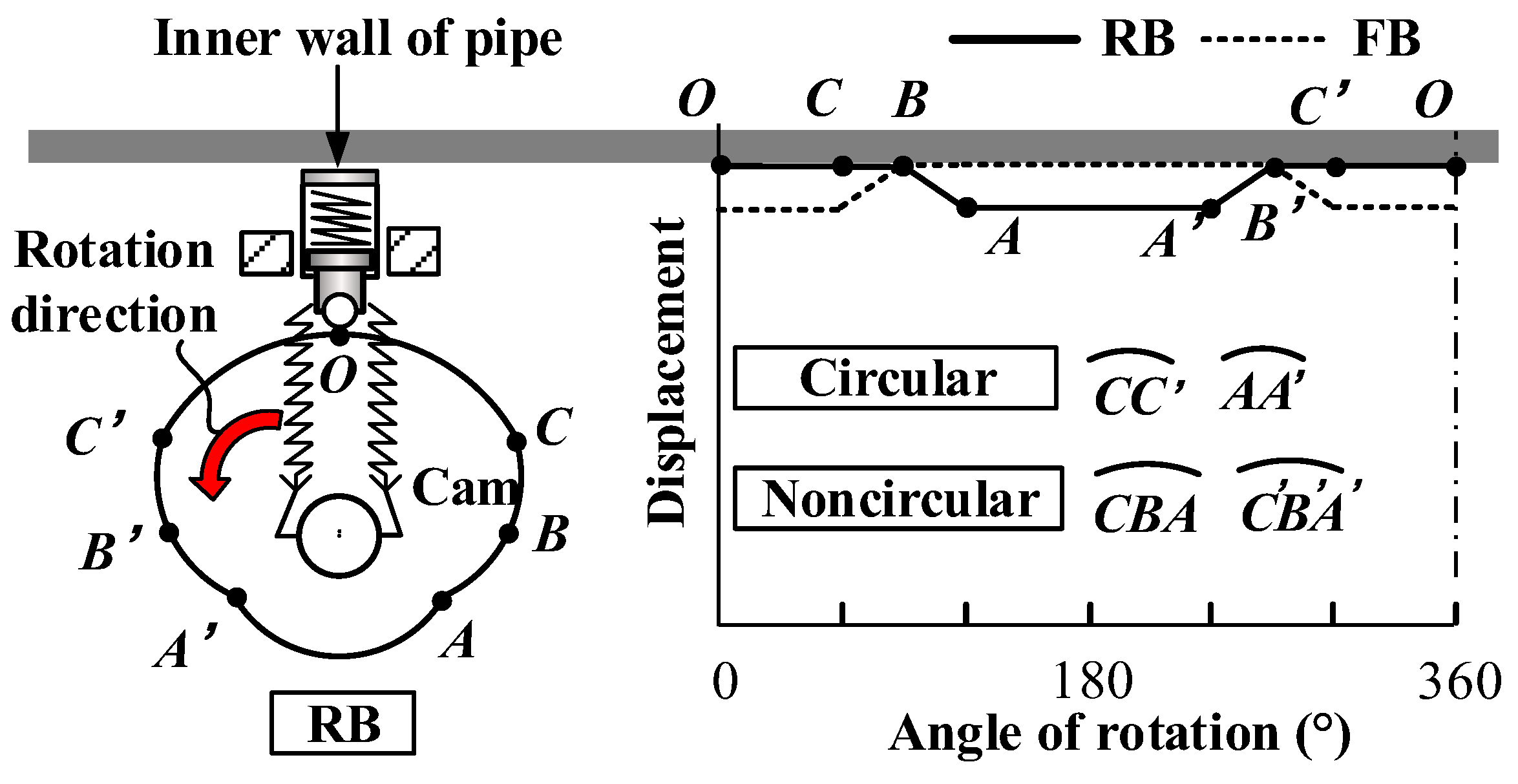
2.2. Detailed Introduction
3. Finding Design Conflicts
- (1)
- Maintaining accurate relative angular positions for the three motor axes over extended periods is challenging. With time and usage, the decline in sensor sensitivity can lead to degradation in the precision of the motors’ relative positioning. This, in turn, results in the robot’s walking motion malfunctioning. This problem is particularly exacerbated in humid pipeline environments, where sensor failures and malfunctions tend to occur more frequently.
- (2)
- Three motors are too many, and the installation space of the robot is limited. In addition, a reducer is required for each motor to improve the driving force. The motors (M1, M2, M3) of the peristaltic robot work at different times. When one motor operates, the other two motors may remain stationary. Therefore, in the design, if three motors can be reduced to one motor and peristaltic walking can be achieved through transmission, it will greatly reduce the number of motors, reducers, and sensors and the control complexity. Therefore, reducing the number of motors and replacing the motors with clever mechanical designs is an important innovation for us.
3.1. Physical Conflict
- (1)
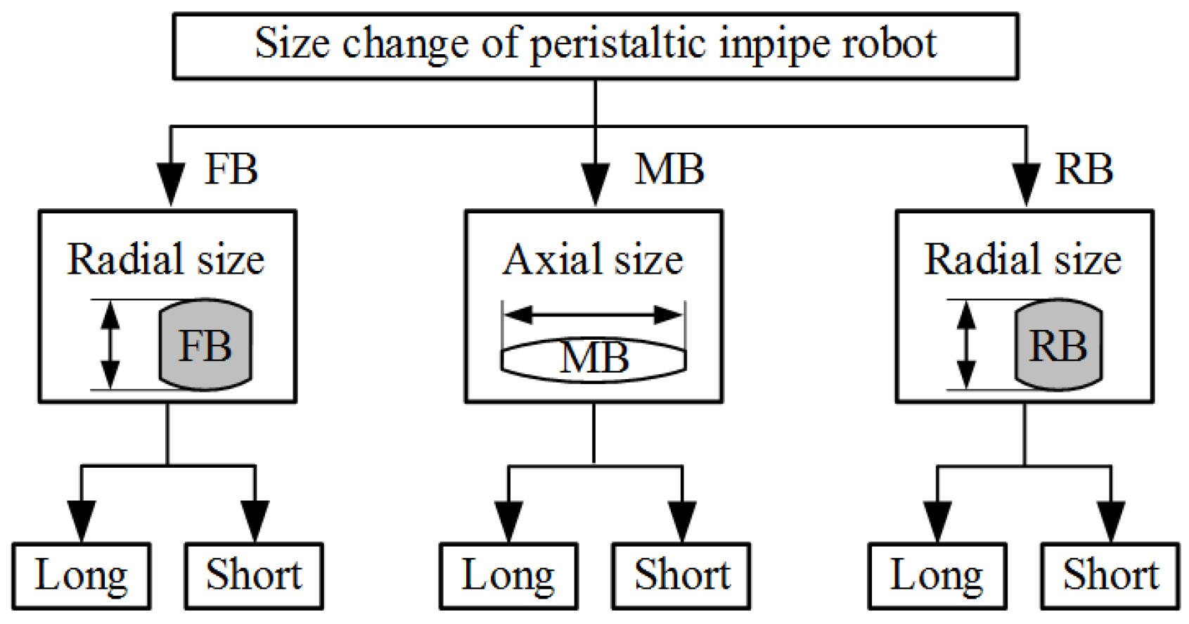
- Physical conflict 1: length and shortness of FB/RB radial dimension.
- (2)
- Physical conflict 2: length and shortness of MB axial dimension.
3.2. Technical Conflict
- (1)
- Technical conflict 1: Control complexity 37 and pipe diameter adaptability 35.
- (2)
- Technical conflict 2: Control complexity 37 and manufacturing difficulty 32.
4. Resolving Design Conflicts
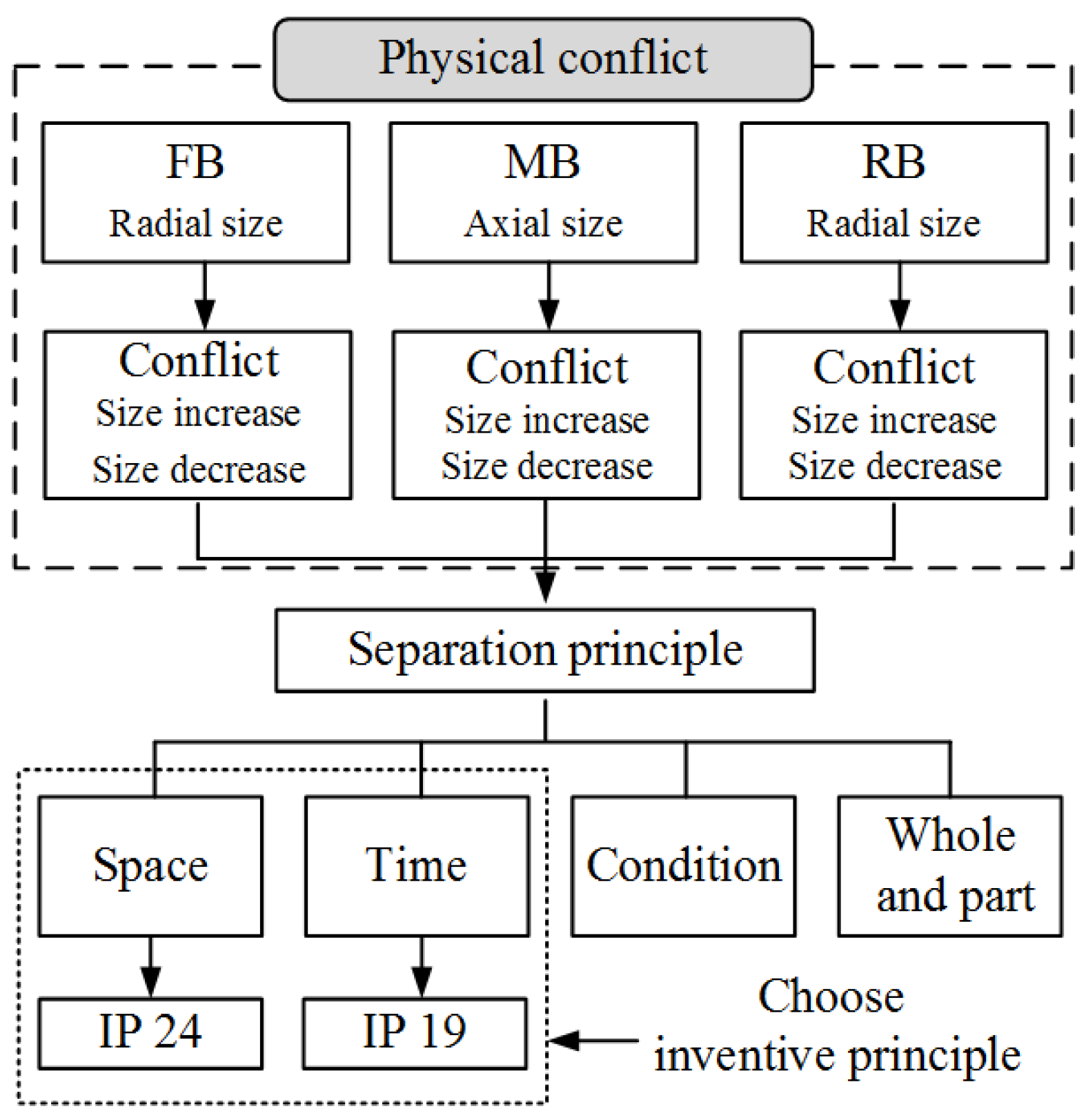
4.1. Inventive Principle 19 (Periodic Action)
4.2. Inventive Principle 24 (Intermediary/Mediator)
4.3. Inventive Principle 1 (Segmentation)
4.4. Inventive Principle 11 (Beforehand Compensation)
5. Parameterized Design of Prototype
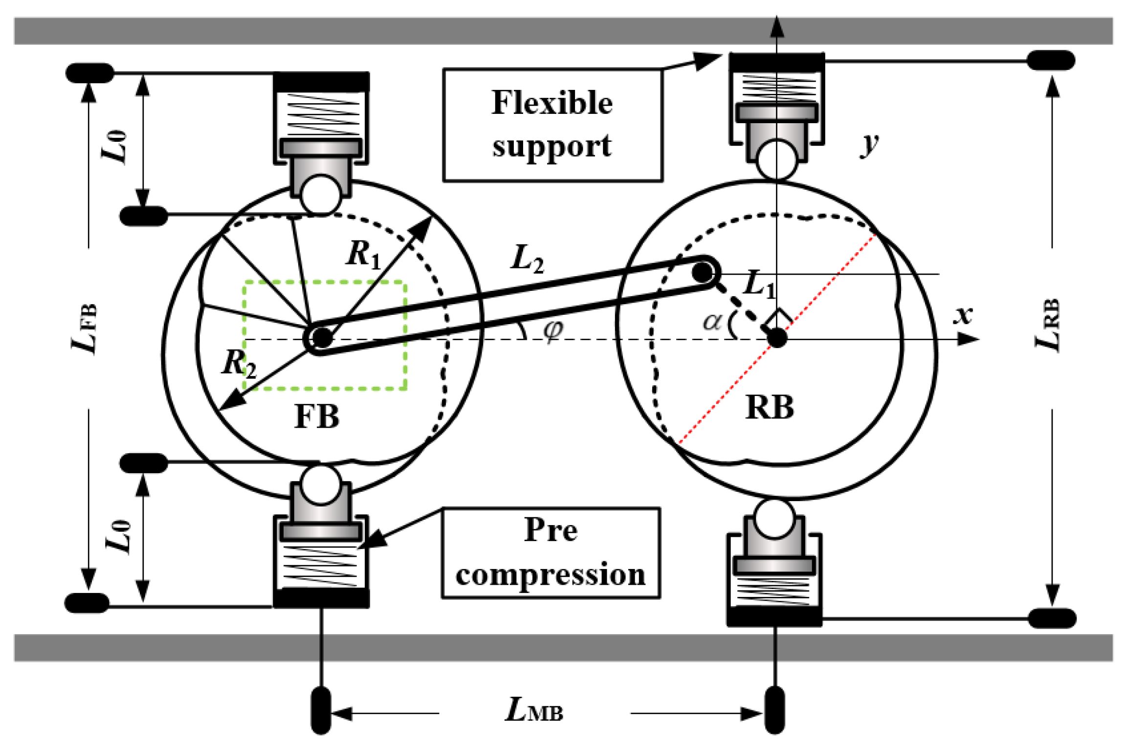
5.1. Geometric Parameters of the Robot
5.2. Dynamic Parameters of the Gear Box
- (1)
- Rotary speed
- (2)
- Input power
- (3)
- Input torque
5.3. Average Walking Speed
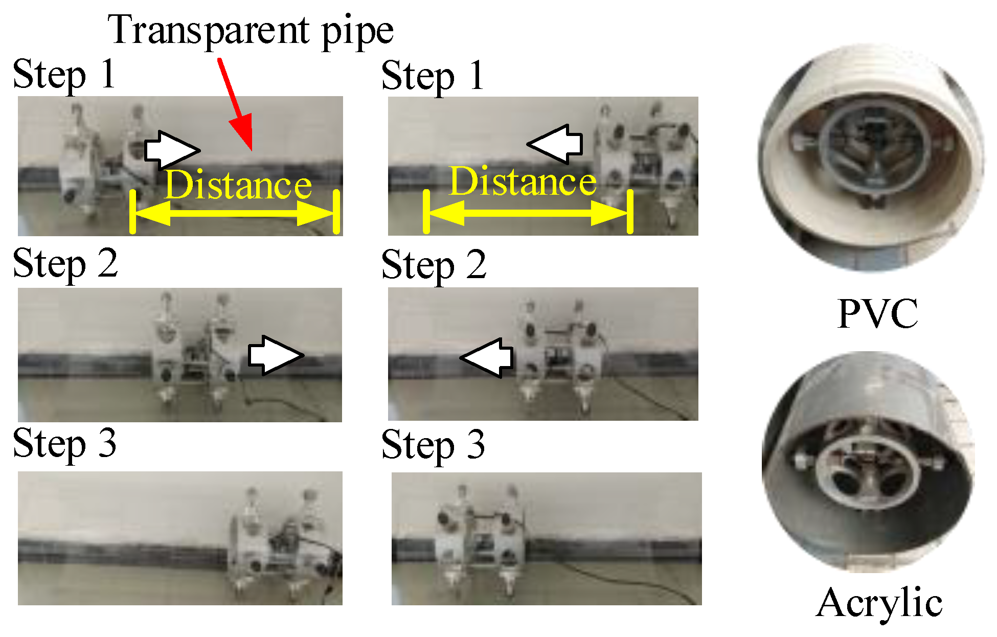
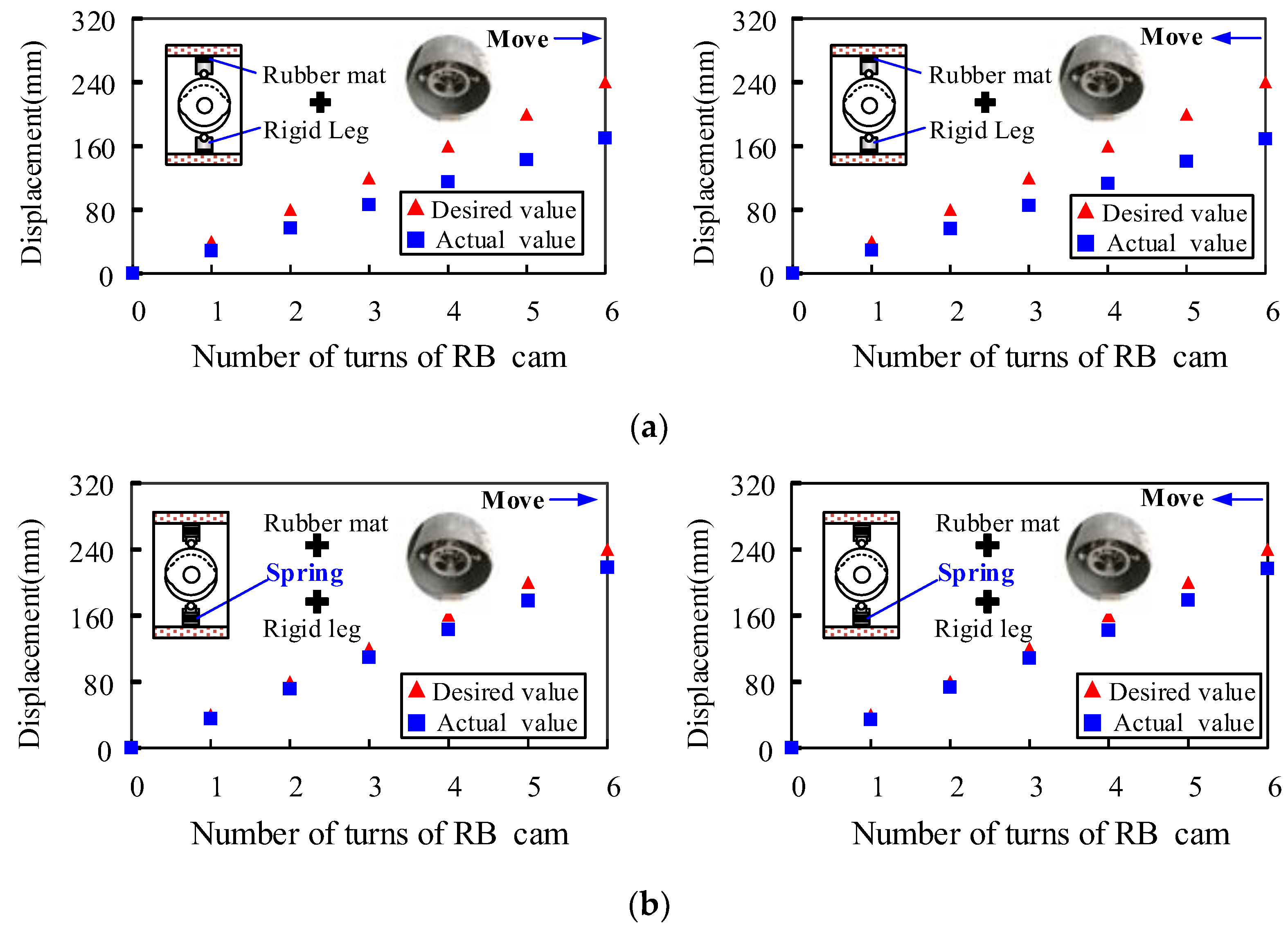
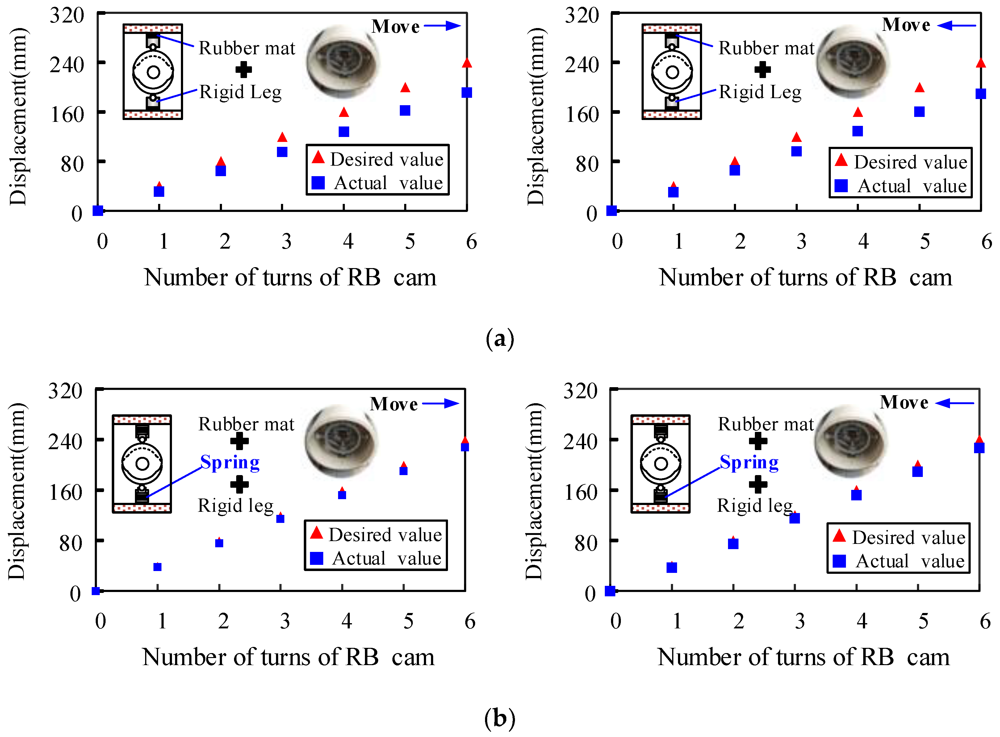
6. Motion Test of Prototype
7. Conclusions
- (1)
- The innovative design of the peristaltic in-pipe robot is executed by raising TRIZ’s conflict resolution theory, effectively resolving physical and technical conflicts encountered in the design process through the corresponding inventive principles.
- (2)
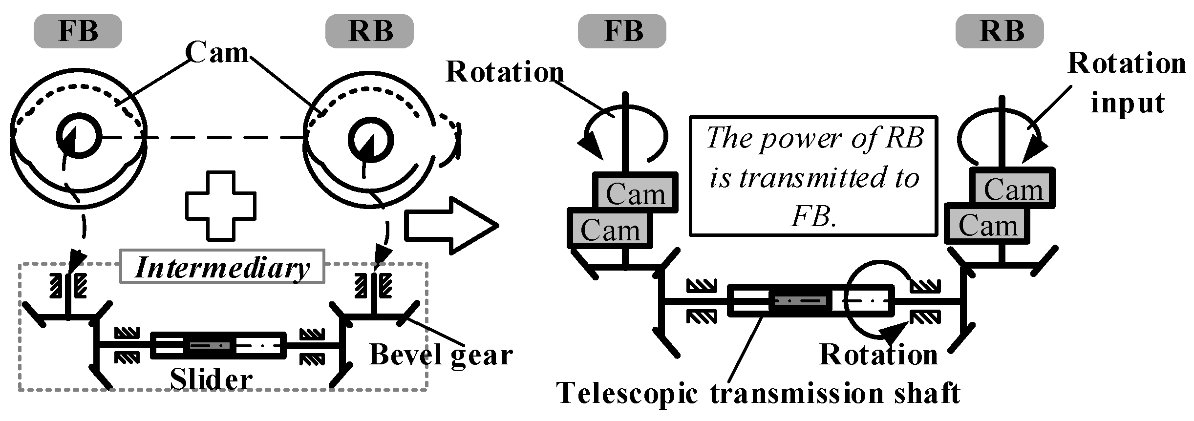
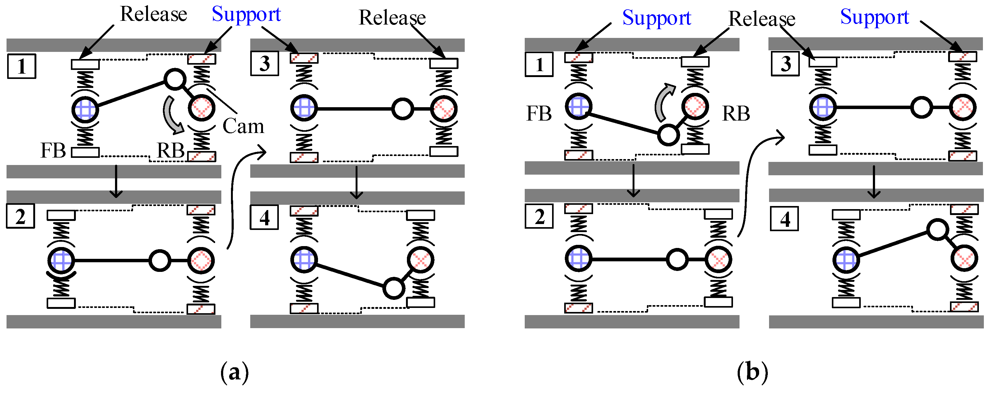
- Taking inspiration from TRIZ’s inventive principles, the periodic expansion of the RB/FB is achieved using a cam mechanism, and power transmission and direction transformation are accomplished through a crank–slider mechanism and telescopic transmission shaft. Control over the single motor’s positive and negative rotation enables the bidirectional movement of the robot. This approach eliminates the need for the cooperative control over multiple motors and complicated control algorithms.
- (3)
- Applying TRIZ’s inventive principle of “segmentation and beforehand compensation”, the support leg (cam follower) is designed as a structure comprising rigid components, pre-compression springs, and rubber padding. The design imparts elasticity to the support leg while maintaining adequate support force, enabling it to adapt to slight variations in pipe diameter and effectively reducing slippage.
- (4)
- The prototype has undergone testing, demonstrating the robot’s ability to move in both directions within a pipe. The results present the effectiveness of the innovative single-drive peristaltic in-pipe robot design based on TRIZ principles. This design methodology can serve as a guideline in product upgrading.
8. Patents
Author Contributions
Funding
Data Availability Statement
Conflicts of Interest
References
- Ilevbare, I.M.; Probert, D.; Phaal, R. A review of TRIZ, and its benefits and challenges in practice. Technovation 2013, 33, 30–37. [Google Scholar] [CrossRef]
- Yang, M.; Xia, Y.; Jia, L.; Wang, D.; Ji, Z. A modular design method based on TRIZ and AD and its application to cutter changing robot. Adv. Mech. Eng. 2021, 13, 1–18. [Google Scholar] [CrossRef]
- Yao, K.-C.; Huang, W.-T.; Xu, J.-R.; Huang, S.-H.; Tsai, C.-T.; Ho, W.-S.; Liao, C.-C. Application of the TRIZ Innovation System Method to Bicycle Handlebars. Machines 2023, 11, 507. [Google Scholar] [CrossRef]
- Chou, J.-R. A TRIZ-based product-service design approach for developing innovative products. Comput. Ind. Eng. 2021, 161, 107608. [Google Scholar] [CrossRef]
- Kang, C.Q.; Ng, P.K.; Liew, K.W. A TRIZ-Integrated Conceptual Design Process of a Smart Lawnmower for Uneven Grassland. Agronomy 2022, 12, 2728. [Google Scholar] [CrossRef]
- Zhao, D.; Chen, W.; Zhong, J. Design and Research of Smart Neck Helmets Based on the KANO-QFD Model and TRIZ Theory. Secur. Commun. Netw. 2021, 2021, 4693719. [Google Scholar] [CrossRef]
- Almeida, S.T.; Mo, J.; Bil, C.; Ding, S.; Wang, X. Conceptual Design of a High-Speed Wire EDM Robotic End-Effector Based on a Systematic Review Followed by TRIZ. Machines 2021, 9, 132. [Google Scholar] [CrossRef]
- Guarino, G.; Samet, A.; Cavallucci, D. PaTRIZ: A framework for mining TRIZ contradictions in patents. Expert Syst. Appl. 2022, 207, 117942. [Google Scholar] [CrossRef]
- Shao, P.; Tan, R.; Peng, Q.; Zhang, L.; Wang, K.; Dong, Y. Problem-Solving in Product Innovation Based on the Cynefin Framework-Aided TRIZ. Appl. Sci. 2022, 12, 4157. [Google Scholar] [CrossRef]
- Bai, Z.-h.; Zhang, S.; Ding, M.; Sun, J.-g. Research on product innovation design of modularization based on theory of TRIZ and axiomatic design. Adv. Mech. Eng. 2018, 10, 168781401881408. [Google Scholar] [CrossRef]
- Li, M.; Ming, X.; Zheng, M.; He, L.; Xu, Z. An integrated TRIZ approach for technological process and product innovation. Proc. Inst. Mech. Eng. Part B J. Eng. Manuf. 2015, 231, 1062–1077. [Google Scholar] [CrossRef]
- Chou, J.-R. An ideation method for generating new product ideas using TRIZ, concept mapping, and fuzzy linguistic evaluation techniques. Adv. Eng. Inf. 2014, 28, 441–454. [Google Scholar] [CrossRef]
- Sauli, S.A.; Ishak, M.R.; Mustapha, F.; Yidris, N.; Hamat, S. Hybridization of TRIZ and CAD-analysis at the conceptual design stage. Int. J. Comput. Integr. Manuf. 2019, 32, 890–899. [Google Scholar] [CrossRef]
- Cempel, C. Application of TRIZ approach to machine vibration condition monitoring problems. Mech. Syst. Sig. Process. 2013, 41, 328–334. [Google Scholar] [CrossRef]
- Şen, N.; Baykal, Y. Development of car wishbone using sheet metal tearing process via the theory of inventive problem-solving (TRIZ) method. J. Braz. Soc. Mech. Sci. Eng. 2019, 41, 390. [Google Scholar] [CrossRef]
- Li, M.; Ming, X.; He, L.; Zheng, M.; Xu, Z. A TRIZ-based Trimming method for Patent design around. Comput.-Aided Des. 2015, 62, 20–30. [Google Scholar] [CrossRef]
- Choi, Y.S.; Kim, H.M.; Mun, H.M.; Lee, Y.G.; Choi, H.R. Recognition of pipeline geometry by using monocular camera and PSD sensors. Intell. Serv. Robot. 2017, 10, 213–227. [Google Scholar] [CrossRef]
- Lee, D.; Park, J.; Hyun, D.; Yook, G.; Yang, H.-s. Novel mechanisms and simple locomotion strategies for an in-pipe robot that can inspect various pipe types. Mech. Mach. Theory 2012, 56, 52–68. [Google Scholar] [CrossRef]
- Kim, H.M.; Choi, Y.S.; Lee, Y.G.; Choi, H.R. Novel Mechanism for In-Pipe Robot Based on a Multiaxial Differential Gear Mechanism. IEEE/ASME Trans. Mechatron. 2017, 22, 227–235. [Google Scholar] [CrossRef]
- Suzumori, K.; Miyagawa, T.; Kimura, M.; Hasegawa, Y. Micro Inspection Robot for 1-in Pipes. IEEE/ASME Trans. Mechatron. 1999, 4, 286–292. [Google Scholar]
- Li, T.; Liu, K.; Liu, H.; Cui, X.; Li, B.; Wang, Y. Rapid design of a screw drive in-pipe robot based on parameterized simulation technology. Simulation 2018, 95, 659–670. [Google Scholar] [CrossRef]
- Li, T. Design and Motion Mechanism of a Screw Drive In-pipe Robot with Adaptability to In-pipe Environment. J. Mech. Eng. 2016, 52, 9–17. [Google Scholar] [CrossRef]
- Nam, J.; Lee, W.; Kim, J.; Jang, G. Magnetic Helical Robot for Targeted Drug-Delivery in Tubular Environments. IEEE/ASME Trans. Mechatron. 2017, 22, 2461–2468. [Google Scholar] [CrossRef]
- Jang, B.; Nam, J.; Lee, W.; Jang, G. A Crawling Magnetic Robot Actuated and Steered via Oscillatory Rotating External Magnetic Fields in Tubular Environments. IEEE/ASME Trans. Mechatron. 2017, 22, 1465–1472. [Google Scholar] [CrossRef]
- Zhang, Y.; Huang, P.; You, B.; Yu, Z.; Li, D.; Dong, G. Design and Motion Simulation of a Soft Robot for Crawling in Pipes. Appl. Bionics Biomech. 2023, 2023, 5334604. [Google Scholar] [CrossRef]
- Liu, Y.; Bi, Q.; Dai, X.; Song, R.; Zhao, J.; Li, Y. TICBot: Development of a Tensegrity-Based In-Pipe Crawling Robot. IEEE Trans. Ind. Electron. 2023, 70, 8184–8193. [Google Scholar] [CrossRef]
- Fang, D.; Jia, G.; Wu, J.; Niu, X.; Li, P.; Wang, R.; Zhang, Y.; Zhang, J. A Novel Worm-like In-Pipe Robot with the Rigid and Soft Structure. J. Bionic Eng. 2023, 23, 1–11. [Google Scholar] [CrossRef]
- Liu, R.; Yao, Y.-a. A novel serial–parallel hybrid worm-like robot with multi-mode undulatory locomotion. Mech. Mach. Theory 2019, 137, 404–431. [Google Scholar] [CrossRef]
- Yang, J.; Xue, Y.; Shang, J.; Luo, Z. Research on a New Bilateral Self-locking Mechanism for an Inchworm Micro In-pipe Robot with Large Traction. Int. J. Adv. Rob. Syst. 2014, 11, 174. [Google Scholar] [CrossRef]
- Qiao, J. Development of an Inchworm In-pipe Robot Based on the Cam Self-locked Principle. J. Mech. Eng. 2010, 46, 83–88. [Google Scholar] [CrossRef]
- Qiao, J.; Shang, J.; Chen, X.; Luo, Z.; Zhang, X. Unilateral self-locking mechanism for inchworm in-pipe robot. J. Cent. South Univ. Technol. 2010, 17, 1043–1048. [Google Scholar] [CrossRef]


| Type | Separation Mode | Inventive Principles (IP) |
|---|---|---|
| 1 | Space | Separating the two parties in conflict in different spaces. |
| 2 | Time | Separating the two parties in conflict at different time periods. |
| 3 | Conditional | Separating the two parties in conflict under different conditions |
| 4 | Whole and part | Separating the two parties in conflict at different levels |
| Type | Separation Mode | Inventive Principles (IP) |
|---|---|---|
| 1 | Space | 1, 2, 3, 4, 7, 13, 17, 24, 26, 30 |
| 2 | Time | 9, 10, 11, 15, 16, 18, 19, 20, 21, 34 |
| 3 | Conditional | 12, 28, 31, 32, 35, 36, 38, 39, 40 |
| 4 | whole and part | 1, 5, 6, 7, 8, 13, 14, 22, 23, 25, 27 |
| No. | Name |
|---|---|
| 1 | Segmentation |
| 2 | Separation/Taking out/Extraction |
| 3 | Local quality |
| 4 | Symmetry change/Asymmetry |
| 5 | Merging/Consolidation |
| 6 | Multifunctionality/Universality |
| 7 | Nested doll |
| 8 | Weight compensation |
| 9 | Preliminary counteraction |
| 10 | Preliminary action |
| 11 | Beforehand compensation |
| 12 | Equipotentiality |
| 13 | Do it in Reverse |
| 14 | Spheroidality/Curature increasel |
| 15 | Dynamic parts/Dynamisation |
| 16 | Partial or excessive actions |
| 17 | Dimensionality change |
| 18 | Mechanical vibration |
| 19 | Periodicaction |
| 24 | Intermediary/Mediator |
| 39 | Inert atmosphere/Inert environment |
| 40 | Composite materials |
| No. | Name | No. | Name |
|---|---|---|---|
| 1 | Weight of moving object | 21 | Power |
| 2 | Weight of stationary object | 22 | Loss of energy |
| 3 | Length of moving object | 23 | Loss of substance |
| 4 | Length of stationary object | 24 | Loss of information |
| 5 | Area of moving object | 25 | Loss of time |
| 6 | Area of stationary object | 26 | Amount of substance |
| 7 | Volume of moving object | 27 | Reliability |
| 8 | Volume of stationary object | 28 | Accuracy of measurement |
| 9 | Speed | 29 | Accuracy of manufacturing |
| 10 | Force | 30 | Harmful factors acting on object |
| 11 | Stress/Pressure | 31 | Harmful side effects |
| 12 | Shape | 32 | Ease of manufacture |
| 13 | Stability of object | 33 | Operability(Ease of operation) |
| 14 | Strength | 34 | Maintainability(Easy of repair) |
| 15 | Durability of moving object | 35 | Adaptability |
| 16 | Durability of stationary object | 36 | Complexity of device |
| 17 | Temperature | 37 | Complexity of control |
| 18 | Brightness | 38 | Automation degree |
| 19 | Use of energy by moving object | 39 | Productivity |
| 20 | Use of energy by stationary object |
| Improved Parameters | Deteriorating Parameter | Inventive Principle |
|---|---|---|
| 37 | 35 | 1, 15 |
| 32 | 5, 28, 11, 29 |
Disclaimer/Publisher’s Note: The statements, opinions and data contained in all publications are solely those of the individual author(s) and contributor(s) and not of MDPI and/or the editor(s). MDPI and/or the editor(s) disclaim responsibility for any injury to people or property resulting from any ideas, methods, instructions or products referred to in the content. |
© 2023 by the authors. Licensee MDPI, Basel, Switzerland. This article is an open access article distributed under the terms and conditions of the Creative Commons Attribution (CC BY) license (https://creativecommons.org/licenses/by/4.0/).
Share and Cite
Xie, Q.; Liu, Q. Application of TRIZ Innovation Method to In-Pipe Robot Design. Machines 2023, 11, 912. https://doi.org/10.3390/machines11090912
Xie Q, Liu Q. Application of TRIZ Innovation Method to In-Pipe Robot Design. Machines. 2023; 11(9):912. https://doi.org/10.3390/machines11090912
Chicago/Turabian StyleXie, Qizhi, and Qiang Liu. 2023. "Application of TRIZ Innovation Method to In-Pipe Robot Design" Machines 11, no. 9: 912. https://doi.org/10.3390/machines11090912
APA StyleXie, Q., & Liu, Q. (2023). Application of TRIZ Innovation Method to In-Pipe Robot Design. Machines, 11(9), 912. https://doi.org/10.3390/machines11090912