Article

Experimental Validation of Current Sensors Fault Detection and Tolerant Control Strategy for Three-Phase Permanent Magnet Synchronous Motor Drives

1
Laboratoire Systèmes Electrotechniques et Environnement (LSEE), Université d’Artois, UR 4025, F-62400 Béthune, France
2
Laboratoire de Génie Electrique de Biskra (LGEB), Biskra 07000, Algeria
*
Author to whom correspondence should be addressed.
Machines 2023, 11(9), 873; https://doi.org/10.3390/machines11090873
Submission received: 5 July 2023 / Revised: 14 August 2023 / Accepted: 17 August 2023 / Published: 31 August 2023
(This article belongs to the Special Issue Fault-Tolerant PM Motors and Drives)

Abstract

:
This paper presents the experimental validation of a Fault-Tolerant Control (FTC) system for Permanent Magnet Synchronous Motor (PMSM) drives, specifically focusing on current sensors. The FTC system is designed to detect and diagnose both single and multiple faults in the current sensors and to reconfigure the control loop to ensure uninterrupted operation in the presence of such faults. Several crucial aspects are addressed in the proposed approach, including fault detection, isolation of faulty sensors, and reconfiguration of the control system through accurate current estimation. To achieve this, a novel adaptation of the Luenberger observer is proposed and employed for estimating the stator currents. The effectiveness of the fault-tolerant control strategy is demonstrated through experimental tests conducted on a 7.2 kW PMSM utilizing a field-oriented vectorial strategy implemented in a dSpace 1104 platform.

1. Introduction

For a wide range of industrial applications, Permanent Magnet Synchronous Motor (PMSM) drive is a suitable choice, notably in the automotive sector [1]. This is because of the high torque density, efficiency, simple structure, and high-speed operation range of the PMSM drive. To operate effectively, PMSM adjustable speed drive requires essential feedback information from several sensors, including a speed/position encoder for precise rotor position feedback, at least two current sensors to monitor stator currents, and a DC-link voltage sensor to measure the voltage level in the DC-link circuit [2]. These sensors provide crucial data for accurate motor control and drive performance. Unfortunately, sensors are highly susceptible to failures and can experience various issues that hinder their proper functioning. These failures may include open circuits, disconnections, gain changes, DC-offset, signal noise, or complete sensor breakdown [3,4]. Such failures can disrupt the accurate measurement and feedback of critical information in a PMSM adjustable speed drive, potentially leading to degraded performance, safety concerns, and the need for appropriate Fault Detection, Isolation, and Reconfiguration (FDIR) mechanisms to ensure the reliable operation of the drive system.
In recent years, there has been significant interest from academics, professionals, and industries in fault-tolerant control systems [5,6]. Fault-Tolerant Control (FTC) schemes have emerged as effective solutions to mitigate the adverse effects caused by faults in various systems [7,8,9,10,11,12,13]. The importance of FTC lies in its ability to ensure system security, reliability, and performance by maintaining system stability even in the presence of failures or breakdowns. These schemes play a crucial role in enhancing the overall resilience and dependability of systems, making them highly relevant to diverse application domains [14,15,16].
FTC strategies can be divided into two main categories: passive and active. Passive FTC involves designing controllers that are robust against failures and uncertainties, enabling them to maintain system stability with acceptable performance degradation when failures occur [17,18,19]. On the other hand, Active Fault-Tolerant Control (AFTC) takes a proactive approach by actively responding to component failures through FDIR mechanisms, reconfiguring the control system to provide appropriate fault-tolerant signals [20,21,22]. This active approach ensures the system’s stability and acceptable performance by dynamically adapting and reconfiguring the control system in the event of faults, thereby preserving the overall system performance. In this respect, this paper deals with the current sensors AFTC.
Active FTC is achieved in three main stages, which are fault detection, isolation, and system reconfiguration [23]. During the fault detection stage, the primary objective is to identify whether a failure has occurred in the system. This stage not only detects the presence of a failure but also determines the specific moment at which the system has experienced the failure event. By accurately distinguishing the occurrence and timing of failures, the fault detection stage plays a crucial role in initiating appropriate actions for fault mitigation, isolation, and recovery within the fault-tolerant control system. In the fault isolation stage, the primary focus is on identifying the specific component or subsystem within the system where the fault originated. This stage aims to narrow down the source of the fault and determine the specific faulty component or subsystem responsible for the observed anomalies or failures. Then, the reconfiguration stage, the last stage of FDIR, involves modifying the system configuration to compensate for the faulty component or subsystem identified during the fault isolation phase. By integrating alternative measurements, estimations, or controllers, system reconfiguration aims to restore the system’s functionality and ensure its continued operation with acceptable performance despite the presence of the fault [24].
Numerous works have been published documenting FTC methods specifically designed for Variable Speed Drives (VSDs) to address the challenges arising from sensor failures. In [25], the extended Kalman filter is proposed to identify the presence of a signal-loss fault for interior PMSM drive. A Sliding Mode Observer (SMO) is presented in [26] as a method to diagnose current sensor faults. The proposed strategy serves two purposes: phase-current error construction and rotor position estimation. However, this method needs appropriate parameters for SMO operation. A technique presented in [27] addresses the issue of failures in speed and current sensors in induction motor (IM) drives. The method utilizes three adaptive observers with different inputs, three current sensors, and a DC-link voltage sensor. However, this technique proves to be inadequate in achieving efficient FTC when two or three sensors fail. In such cases, the system can operate in a speed-sensorless mode when the speed sensor fails, or it can utilize the speed sensor, two current sensors, and the DC-link voltage sensor when one of the current sensors is faulty. To address these limitations, the same author has made improvements to the method [28]. In this revised approach, only two current sensors are employed, as opposed to the three used in [27]. Furthermore, the enhancements described in [28] enable the method to operate with a single current sensor in addition to the DC-link voltage sensor. However, it is important to note that even with these improvements, the number of adaptive observers remains unchanged at three. Speed and current sensor fault-tolerant induction motor drive is presented in [29]. This method uses three full-order observers, the first one under healthy sensor operation, the second one under speed sensor fault operation, and the last one under current sensor fault operation. Similarly, ref. [30] presents a fault-tolerant operation method for induction motor drives incorporating automatic controller reconfiguration. The method employs four distinct controllers to address different types of faults that may arise. Several studies, including [1,31,32,33], have also employed the approach of multi-controllers. However, a significant drawback of this method, as pointed out in [33], is that implementing some of these techniques can be challenging from an experimental standpoint. A model reference adaptive system is used twice for speed and current sensor FTC in [34]. In [35], a sensor fault-detection algorithm based on a parity-space scheme is presented. The algorithm, as stated in the paper, demonstrates insensitivity towards parameter variations since it does not rely on any model knowledge. However, it should be noted that this algorithm does not facilitate the compensation of sensor faults, as it does not employ an estimator.
The present study introduces several noteworthy features that differentiate it from previously proposed approaches:
  • Instead of employing two or three observers to estimate line currents, the proposed method utilizes only one observer to generate the three-phase stator currents.
  • The proposed method is designed to enable fault detection, isolation, and reconfiguration in scenarios where two or three current sensors experience consecutive interruptions. As a result, the system can continue operating with the desired performance, even in the absence of any current sensor.
  • This technique allows for adaptive reorganization in case the faulty sensors are restored or replaced. This adaptability ensures that the control system can maintain its maximum performance by leveraging the complementary nature of the other sensors.
  • The study considers three different types of sensor failure: complete sensor outage, gain drop, and start-up with DC-offset fault. These specific failures have not been adequately addressed in the existing literature, and their inclusion serves to validate the accuracy of estimation and fault detection.

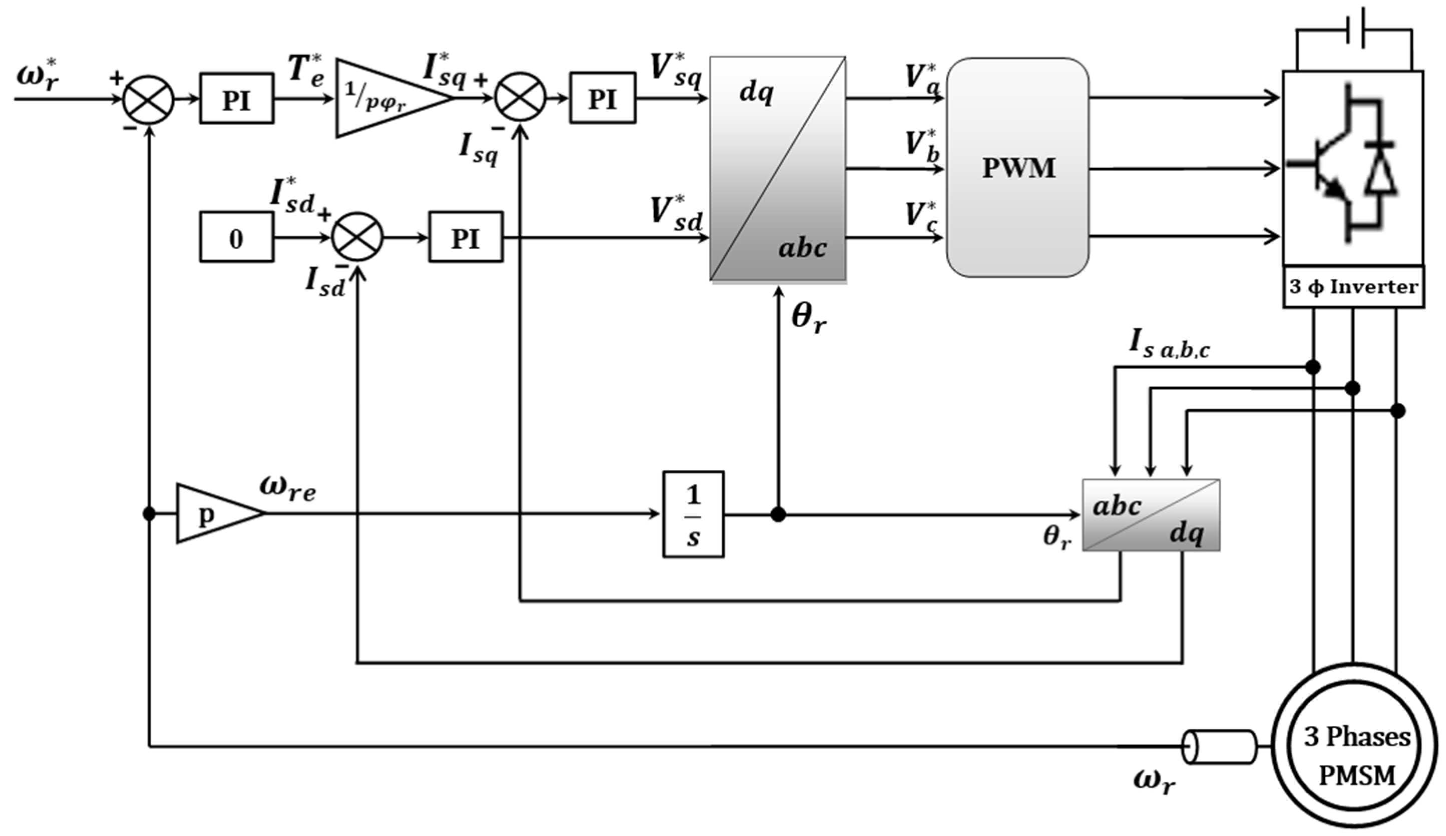
2. Permanent Magnet Synchronous Motor Model and Its Control

The mathematical representation of the PMSM model involves two differential equations that describe the stator currents in the synchronous reference frame (d,q). These equations can be expressed using the following expressions:
d I s d d t = R s L d I s d + ω r e L q L d I s q + 1 L d V s d d I s q d t = R s L q I s q ω r e L d L q I s d + 1 L q V s q ω r e 1 L q ϕ r
The state equation for the PMSM model, as described in (1), is expressed as follows:
X ˙ = A X + B U
where:
A = R s L d L q L d ω r e L q L d ω r e R s L q ;   X = I s d I s q ;   B = 1 L d 0 0 0 1 L q 1 L q ω r e ;   U = V s d V s q ϕ r ;   ω r e = p Ω r
and the following equation gives the electromagnetic torque:
T e m = p L d L q I s q I s d + ϕ r I s q
whereas the process of converting electrical energy into mechanical energy in rotating machinery is characterized by the following equation:
J d Ω r d t = T e m T l F Ω r
Accurate control of the current, like the need for precise torque control, is essential in machine drives to prevent saturation resulting from high currents flowing through the stator magnetic circuit. To address this, precise control of PMSM drives can be achieved using direct vector control, which involves regulating the direct and quadrature currents as well as the speed.
Figure 1 presents a fundamental diagram of direct vector control for PMSM.

3. Current Sensor Fault-Tolerant Control

In the event of system failure, the recommended course of action involves activating an emergency alarm, determining the nature of the fault, and devising a plan to address it [36]. Active fault-tolerant control relies on detecting faults, pinpointing their source, implementing measures to isolate the faulty components, and reconfiguring the system.

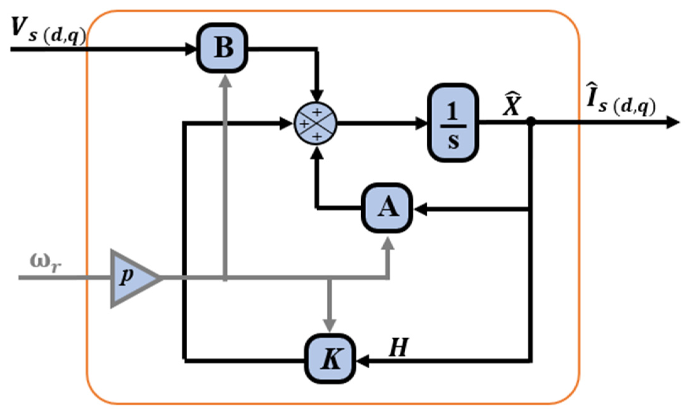
3.1. Stator Current Estimation

To estimate the three-phase currents, a state observer is utilized, which is based on the PMSM model outlined in (2). The concept behind the proposed stator current estimator is rooted in the overall theory of an adaptive state observer [37,38], which makes it possible to estimate variable or unidentified parameters of a non-linear system. The equation of the adaptive state observer is presented in (5), where the symbol “^” indicates the estimated values.
X ˙ = A X ^ + B U + K H
where:
X ^ = I s d ^ I s q ^   and   H = I s d ^ I s d I s q ^ I s q
In this modified form of the observer, the measured currents are not considered because the observer is built to estimate them; thus, the vector H can be defined as follows:
H = I s d ^ I s q ^
For the conventional applications of this observer, rotor speed is the estimated variable [39]. As indicated above, in this paper, the observer is used to estimate the stator currents. For this reason, the electrical pulsation ω r e is considered an input, as are the direct and quadrature voltages V s d and V s q (see Figure 2).
K is the gain matrix, defined as described in [40] using the pole placement method, and is given as follows:
K = λ R s L d 0 0 λ p ω r e
where λ is a positive constant.

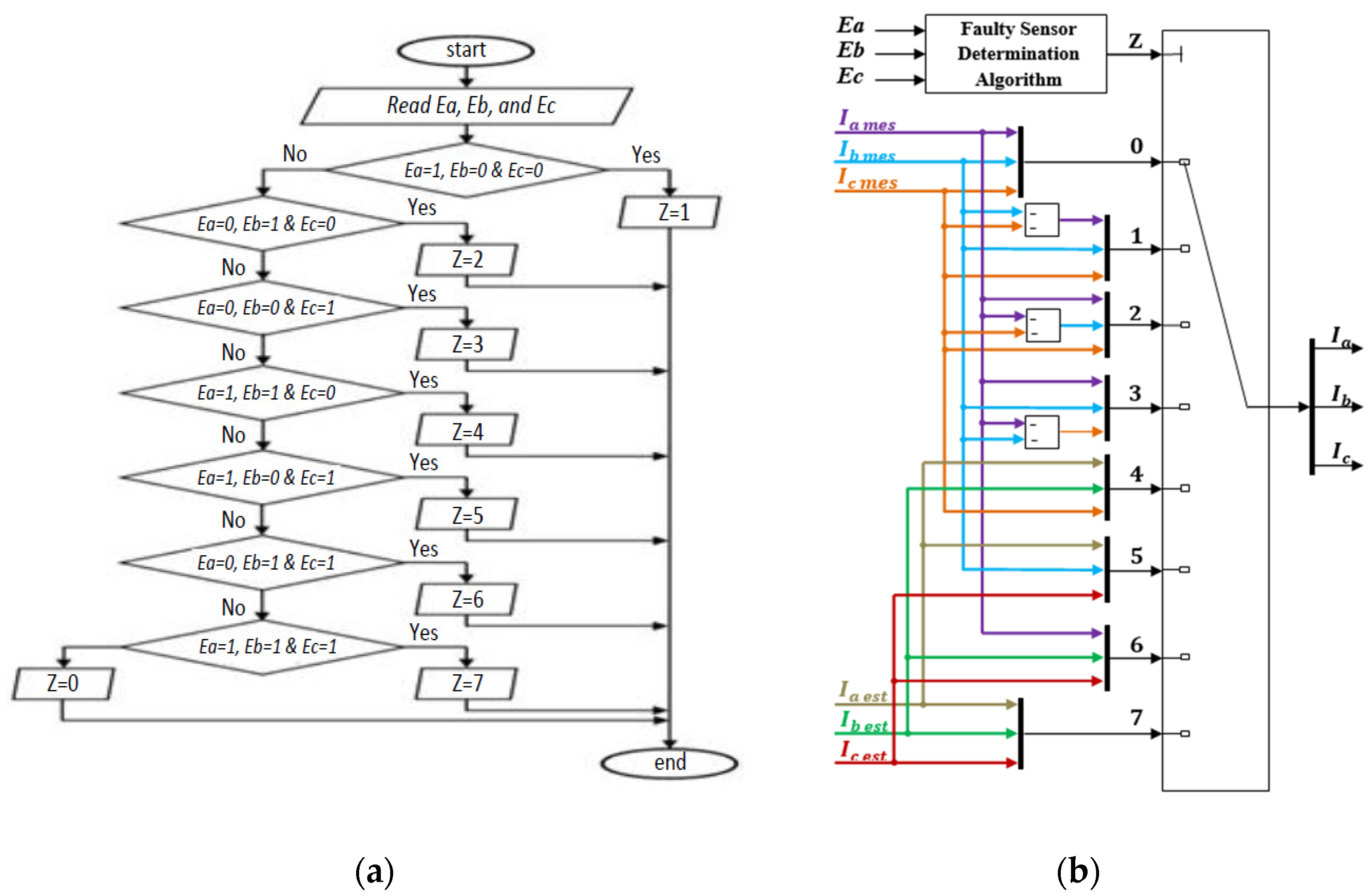
3.2. Fault Detection, Isolation, and Reconfiguration

An essential aspect of the fault detection, isolation, and reconfiguration (FDIR) system is its ability to accommodate system changes, including the reinstatement of faulty sensors. This adaptability plays a crucial role in maintaining the system’s operational capabilities despite the presence of faults, ensuring reliability and robustness. By adapting and reconfiguring in response to system changes, the FDIR system effectively minimizes downtime and mitigates the impact of faults on overall system performance.
The logic circuit depicted in Figure 3 serves the purpose of ensuring fault detection (FD) by analyzing the residual signal generated from the comparison between measured and estimated quantities. To extract the relevant signal, a low pass filter (LPF) is employed. The resulting filtered signal is then compared with a threshold value. Extensive laboratory testing has been conducted under various test scenarios, demonstrating that the maximum error between the estimated currents and the measured currents remains below 0.8 A. As a result, for this PMSM, a threshold of 0.85 A was selected. This threshold value corresponds to approximately 6% of the rated current of the PMSM being used, ensuring a robust and accurate fault-detection mechanism within the system. The FD logic circuit produces three impulses, namely Ea, Eb, and Ec, at each sampling instant in the following manner:
E n = 0   H e a l t h y   s t a t e 1   F a u l t y   s t a t e   with :   n = a , b , c
The flowchart shown in Figure 4a takes the three impulses (Ea, Eb, and Ec) and utilizes them to generate an index, denoted as Z. The value of Z ranges from 0 to 7, depending on the states of the sensors. Table 1 provides a summary of the various combinations of sensor states.
Using the Z values depicted in Figure 4b, a multi-port switch is employed for fault isolation and system reconfiguration to choose the appropriate current components, which substitute the faulty sensor information.

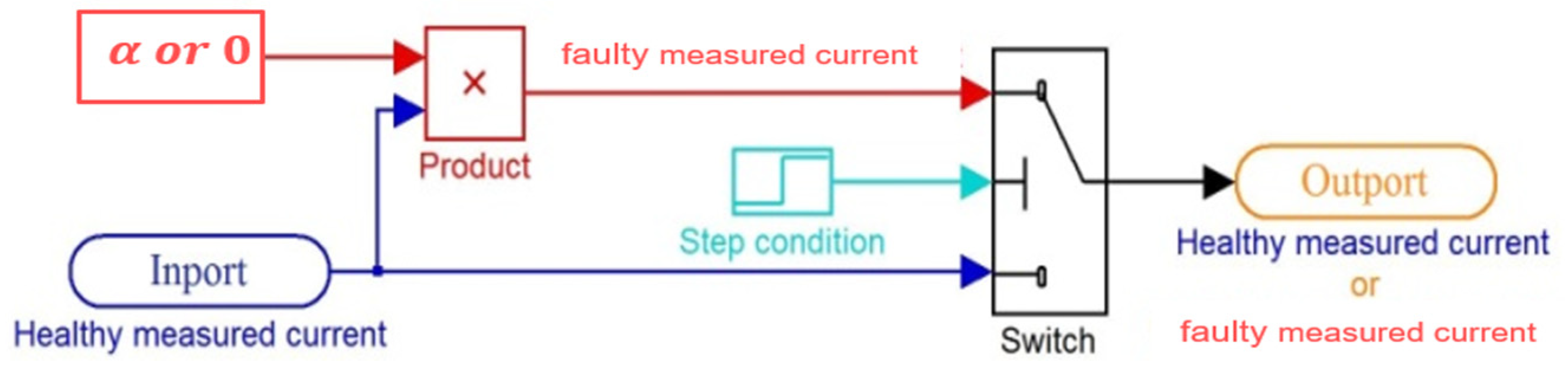
3.3. Considered Defects and Their Modelization

The experiments presented in this paper were carried out using three Hall effect current sensors, namely sensor-a, sensor-b, and sensor-c. These sensors were positioned in phase-a, phase-b, and phase-c, allowing for the measurement of line currents I s a , I s b , and I s c , respectively.
Several failures can appear in the Hall effect current sensor, as mentioned in [3,4]. In this paper, three of these are considered, namely gain fault, complete outage of the sensor, and DC-offset. These faults have been modeled, as shown in Table 2.
To obtain the different faults in the sensors, two MATLAB/Simulink blocks were included. Figure 5 displays the block diagram that was implemented to induce the gain fault and the complete outage of the current sensors, and Figure 6 shows the one used to introduce the DC-offset.
Figure 7 illustrates the proposed fault-tolerant control scheme designed to handle current sensor failures, wherein a single estimator is employed to reconstruct the three-line currents (a, b, and c), and a voltage vector synthesizer utilizes the measured DC-link voltage and PWM vector control switching signals (Sa, Sb, and Sc) to generate the three-phase stator voltages.

4. Results and Discussion

The experimental validation of the proposed FTC for the PMSM drive was performed at the electrical systems and environment laboratory (LSEE) of Artois University on a test bench, as shown in Figure 8. The test bench was composed of a 7.2 kW PMSM, a Permanent Magnet Synchronous Generator (PMSG), a dSpace 1104 card, an autotransformer, an incremental encoder, a DC-voltage sensor, three Hall effect current sensors, and a power electronics SEMIKRON® module (consisting of a rectifier and an IGBT inverter). The parameters of the PMSM are given in Appendix B and all nomenclatures are in Appendix A.
For this experimental validation, five scenarios were considered.

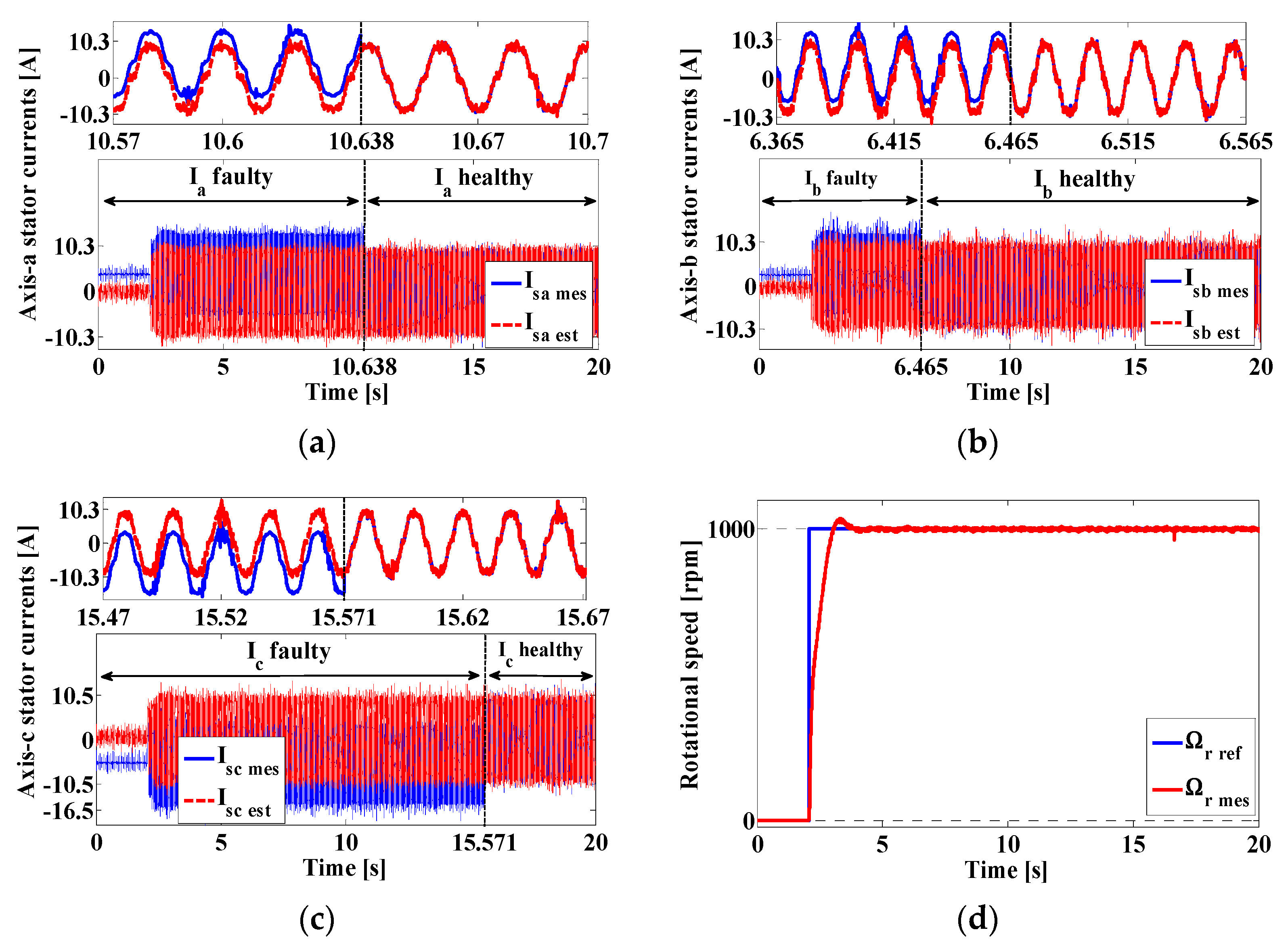
4.1. First Scenario: Gain Faults in Sensor-b and Sensor-c

Figure 9 presents the results of the first scenario in the experimental validation of the proposed fault-tolerant control; this test was performed at a rated speed (3000 rpm) and nominal load (25 N.m). Using the Simulink block given in Figure 5, a +35% gain fault was introduced in sensor-b at t = 10.76 s and another one of −40% was introduced in sensor-c at t = 14.34 s, but sensor-a remained healthy, as shown in Figure 9a–c. The failure of the two sensors was detected immediately by the fault detection system, where we can see in Figure 9e that the fault indicator changed from 0 to 2 and then to 6, but the machine operation was not interrupted (see Figure 9d,g). Figure 9f shows the error (Err) between the measured current and the estimated current for each phase compared with the fault threshold (Th). Accordingly, the isolation and reconfiguration system replaced the faulty sensors with the estimated currents when the error surpassed the threshold.

4.2. Second Scenario: Complete Outage of the Three Current Sensors

During this trial, as shown in Figure 10, the PMSM drive system was initiated with healthy current sensors, resulting in a fault index of 0. At t = 8.69 s, a failure occurred in sensor-a, causing an abrupt interruption in the phase-a current measurement (Figure 10a). As a result, the fault indicator immediately rose to 1 (Figure 10e), prompting the replacement of the faulty sensor-a through proper estimation. Subsequently, at t = 12.52 s and t = 16.82 s, total failures in sensor-b and sensor-c were introduced, respectively, further increasing the severity of this abnormal condition (Figure 10b,c). Figure 10e shows the changes in the fault indicator (Z), which increased to 4 and then to 7, identifying the faulty current sensors and prompting their replacement with estimated currents. Additionally, the results depicted in Figure 10d confirm the effectiveness of the proposed fault detection and isolation mechanism in maintaining high-performance speed tracking despite the abnormal operating conditions.

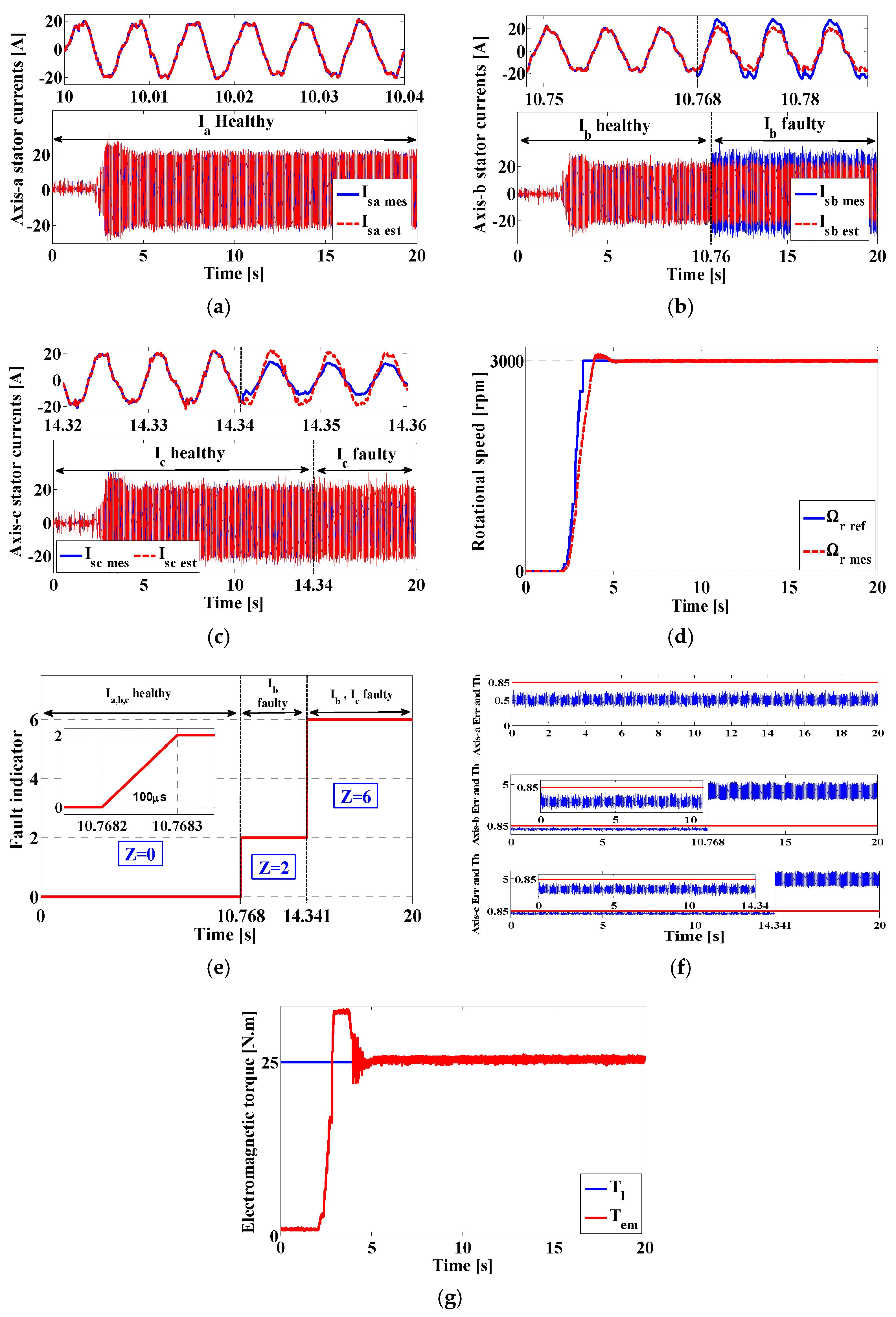
4.3. Third Scenario: Start-Up with a DC-Offset Fault in the Three Current Sensors

The aim of this test was not only to assess the performance and suitability of the proposed FTC system and current estimator in the case of a start-up transient with faulty current sensors but also to observe the behavior of this strategy during sensor recovery to a healthy state. As shown in Figure 11a–c, actual and estimated stator currents were determined during the start-up process of the PMSM drive system, while all three current sensors were experiencing a DC-offset failure. Upon the initialization of the drive system, the fault indicator was at 7 (as seen in Figure 11e), indicating that all three current sensors were providing incorrect measurements.
To deal with this situation, the estimated currents were employed to ensure a successful start-up. As the test progressed, sensor-b was the first to recover at t = 6.46 s, as seen in Figure 11b, and the fault indicator value decreased to 5, indicating the recovery of sensor-b, while the other two sensors remained in a faulty state. Following sensor-b, sensor-a recovered at t = 10.63 s, as seen in Figure 11a, and the fault indicator value decreased further to 3, indicating the recovery of sensor-a and sensor-b, but sensor-c remained in a faulty state. Finally, sensor-c recovered at t = 15.57 s, as seen in Figure 11c, and the fault index value became 0, indicating the overall healthy state of the system. The actual and reference speeds for this test can be seen in Figure 11d for a speed set of 1000 rpm at 25 Nm load torque. Therefore, the FTC operating system performs well under these conditions.

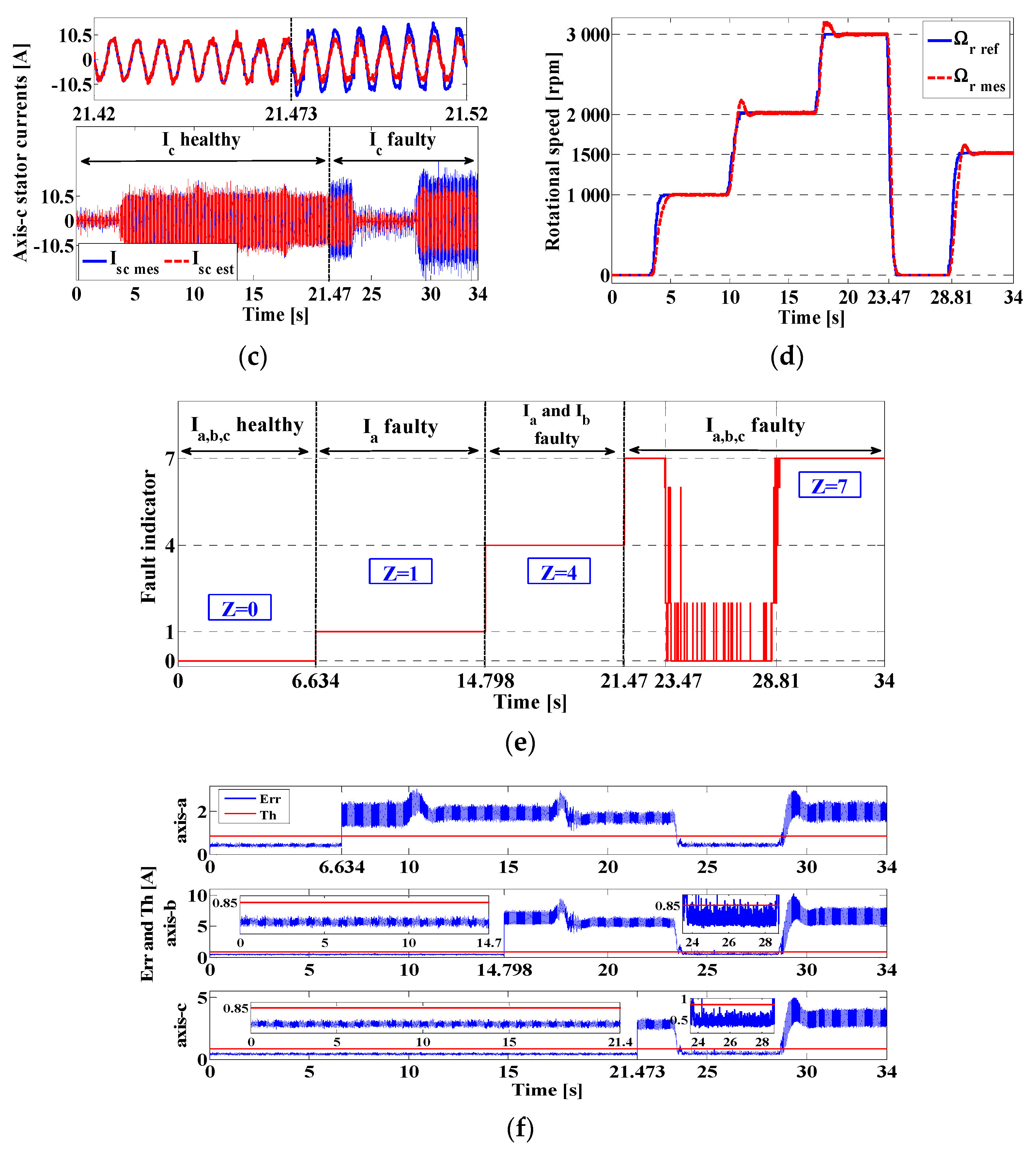
4.4. Fourth Scenario: Sensor Failure under Variable Speed Conditions

The results in Figure 12 demonstrate the effectiveness of the proposed FTC method under speed variation and rated load torque conditions. In the experiment, faults were introduced in the current sensors at specific points in time, and the results of the measured and estimated stator currents are displayed in Figure 12a–c.
Figure 12d illustrates the reference speed profile and the actual measured rotor speed, with the reference speed increasing and decreasing multiple times. The results show that the proposed FTC algorithm and current estimator were able to function effectively, even with the introduction of sensor faults.
Figure 12f shows the error between measured and estimated currents and the threshold. From t = 23.47 s to t = 28.81 s, the fault indicator is swinging between 0 and 2 instead of being at 7, as the three current sensors are faulty during this time interval. This is due to the rotational speed being decreased to 0 rpm, which leads to the drop of the load torque to 0 N.m since the load is an AC generator connected to a resistive load.

4.5. Fifth Scenario: Sensor Failure under Variable Load Conditions

This experiment was carried out under conditions where three current sensors failed in succession. The stator currents were measured and estimated, and the results are presented in Figure 13a–c.
Figure 13d shows the speed reference step and the measured rotor speed. The failures in the sensors were detected and identified, as shown in Figure 13e, and the fault indicator signal was plotted. The variation in the load and electromagnetic torque is also presented in Figure 13f, showing changes from 0 N.m to 12.5 N.m (50% of the rated load torque), then to 25 N.m (100% load torque), and finally to 6 N.m (25% of the rated load torque). The results proved the system’s ability to maintain its control performance even under complex scenarios of faulty sensors and load variations.

5. Conclusions

The paper proposes a fault-tolerant control strategy for a permanent magnet-synchronous motor drive. The strategy is based on the vector control approach, which was chosen for its simplicity, low computational time, and widespread use in various AC electrical drive applications. The objective of the strategy is to improve the performance of the PMSM drive in the event of current sensor failure. The Luenberger observer is a widely used system for state estimation in non-linear systems. By using additional measurements, such as the DC-link voltage and rotor speed, a modified version of the observer can be designed to estimate the three stator currents. This modified observer may provide more accurate and robust estimates of the system states. A system for detecting faults in the current sensors has been implemented. The system uses a fault detection algorithm that generates a fault indicator upon detection of a failed sensor. Then, a decision-making logic circuit uses the fault indicator value to select the correct current component through a multi-port switch, ensuring continued operation without interruption. The FTC strategy was tested on an experimental test bench to determine its effectiveness, response, and performance. The results of the experiments confirm that the strategy is effective, responsive, and well-performing. The proposed FDIR scheme and current estimator were tested and shown to produce fast and accurate results, even when current sensors failed in succession and in the case of start-up transients with varying speed and load torque. The accuracy of the diagnosis was verified by examining three different faults (complete sensor outage, gain drop/rise, and start-up with offset fault) under varying conditions that could impact measured quantities. Additionally, as demonstrated through the experiments, the suggested failure detection and reconfiguration system has the ability to adapt and reorganize itself in the case of faulty sensor recovery. This feature enables the control system to maintain its top performance by leveraging the complementary relationship between the other sensors. To sum up, it is evident that the proposed fault-tolerant control system (failure detection and isolation system combined with current estimator) is an effective solution for several PMSM drive applications where current sensors are prone to failure. The high accuracy of the stator current estimation is a critical aspect in detecting sensor malfunctions. As a result, the prosed FTC approach can effectively monitor and compensate for any potential failures in the current sensors, ensuring reliable and accurate current measurements.
It is a common characteristic that each method has its limitations. The method proposed in this paper is atypical as it is not standardized, and its application varies from one system to another. Moreover, it is also sensitive to high temperatures, which can result in significant parametric variations.
Currently, a technique rooted in artificial intelligence is being actively explored. The results of this research endeavor will be disseminated through an upcoming publication. Notably, this methodology goes beyond merely ascertaining the existence or absence of faults. It also possesses the capability to differentiate the specific attributes of the fault at the sensor level, all while evaluating whether the decline in performance can be attributed to the propagation of faults.

Author Contributions

Conceptualization, Y.A.; methodology, Y.A., R.P. and M.S.; software, Y.A. and T.A.; validation, Y.A. and T.A.; formal analysis, R.P., M.S. and R.R.; investigation, Y.A.; resources, Y.A.; data curation, Y.A. and R.P.; writing—original draft preparation, Y.A.; writing—review and editing, R.P., R.R. and M.S.; visualization, R.R.; supervision R.R.; project administration, R.R., M.S. and R.P.; All authors have read and agreed to the published version of the manuscript.

Funding

The APC was funded in part by the “Ouvrages et Articles Scientifiques” program of Artois University. This initiative is aligned with the University’s strategy to support open access to scientific publications.

Data Availability Statement

Not applicable.

Conflicts of Interest

The authors declare no conflict of interest.

Appendix A

Nomenclature
V d c   Inverter input voltage [V]
V s d ,   V s q d-q axis stator voltages [A]
I s d ,   I s q d-q axis stator currents [A]
I ^ s d , I ^ s q d-q axis estimated stator currents [A]
L d   , L q Direct and quadrature inductances [H]
T e m ,   T l Electromagnetic and load torques [N.m]
ω r * , ω r Reference and measured rotational speeds [rad/s]
ω r e = p ω r Electrical measured rotational speed
Ω r   r e f ,   Ω r   m e s Reference and measured rotational speeds [rpm]
θ r Rotor position [rad]
ϕ r Rotor magnet flux [Wb]
p Number of pole pairs
I s a   m e s ,   I s b   m e s ,   I s c   m e s (a,b,c) axis measured stator currents [A]
I s a   e s t ,   I s b   e s t ,   I s c   e s t (a,b,c) axis estimated stator currents [A]

Appendix B

PMSM SpecificationsParameters
Nominal power [kW]7.4 R s [Ω]0.7
Nominal voltage [V]400 L d [H]0.007
Nominal current [A]14.7 L q [H]0.007
Frequency [Hz] 150 ϕ r [Wb]0.225
Number of pole pairs3 J [Kg.m2]0.000629
Nominal speed [rpm]3000F [N.m.s.rad−1]0.0003025
Nominal torque [N.m]23.4

References

  1. Benbouzid, M.E.H.; Diallo, D.; Zeraoulia, M. Advanced Fault-Tolerant Control of Induction-Motor Drives for EV/HEV Traction Applications: From Conventional to Modern and Intelligent Control Techniques. IEEE Trans. Commun. 2007, 56, 519–528. [Google Scholar] [CrossRef]
  2. Azzoug, Y.; Sahraoui, M.; Pusca, R.; Ameid, T.; Romary, R.; Cardoso, A.J.M. A Variable speed control of permanent magnet synchronous motor without current sensors. In Proceedings of the 2020 IEEE 29th International Symposium on Industrial Electronics (ISIE), Delft, The Netherlands, 17–19 June 2020; pp. 1523–1528. [Google Scholar]
  3. Lee, K.-S.; Ryu, J.-S. Instrument Fault Detection and Compensation Scheme for Direct Torque Controlled Induction Motor Drives. IEE Proc. Control Theory Appl. 2003, 150, 376–382. [Google Scholar] [CrossRef]
  4. Skowron, M.; Teler, K.; Adamczyk, M.; Orlowska-Kowalska, T. Classification of Single Current Sensor Failures in Fault-Tolerant Induction Motor Drive Using Neural Network Approach. Energies 2022, 15, 6646. [Google Scholar] [CrossRef]
  5. Hwang, I.; Kim, S.; Kim, Y.; Seah, C.E. A Survey of Fault Detection, Isolation, and Reconfiguration Methods. IEEE Trans. Control Syst. Technol. 2010, 18, 636–653. [Google Scholar] [CrossRef]
  6. Campos-Delgado, D.U.; Espinoza-Trejo, D.R.; Palacios, E. Fault-Tolerant Control in Variable Speed Drives: A Survey. IET Electr. Power Appl. 2008, 2, 121–134. [Google Scholar] [CrossRef]
  7. Cristian, F.; Dancey, B.; Dehn, J. Fault-Tolerance in Air Traffic Control Systems. ACM Trans. Comput. Syst. 1996, 14, 265–286. [Google Scholar] [CrossRef]
  8. Lee, J.S.; Kim, M.C.; Seong, P.H.; Kang, H.G.; Jang, S.C. Evaluation of Error Detection Coverage and Fault-Tolerance of Digital Plant Protection System in Nuclear Power Plants. Ann. Nucl. Energy 2006, 33, 544–554. [Google Scholar] [CrossRef]
  9. Chen, Q.; Liu, G.; Gong, W.; Zhao, W. A New Fault-Tolerant Permanent-Magnet Machine for Electric Vehicle Applications. IEEE Trans. Magn. 2011, 47, 4183–4186. [Google Scholar] [CrossRef]
  10. Bennett, J.W.; Atkinson, G.J.; Mecrow, B.C.; Atkinson, D.J. Fault-Tolerant Design Considerations and Control Strategies for Aerospace Drives. IEEE Trans. Ind. Electron. 2012, 59, 2049–2058. [Google Scholar] [CrossRef]
  11. Aouzellag, H.; Ghedamsi, K.; Aouzellag, D. Energy Management and Fault Tolerant Control Strategies for Fuel Cell/Ultra-Capacitor Hybrid Electric Vehicles to Enhance Autonomy, Efficiency and Life Time of the Fuel Cell System. Int. J. Hydrogen Energy 2015, 40, 7204–7213. [Google Scholar] [CrossRef]
  12. Wang, M.; Deng, J.; Pattinson, C.; Richardson, S. A Fuzzy controller for fault tolerant control of nuclear reactor. In Proceedings of the 2017 International Conference on Computational Science and Computational Intelligence (CSCI), Las Vegas, NV, USA, 14–16 December 2017; pp. 387–390. [Google Scholar]
  13. Habibi, H.; Howard, I.; Simani, S. Reliability Improvement of Wind Turbine Power Generation Using Model-Based Fault Detection and Fault Tolerant Control: A Review. Renew. Energy 2019, 135, 877–896. [Google Scholar] [CrossRef]
  14. Rahman, S.U.; Xia, C. Rotor Speed and Position Estimation Analysis of Interior PMSM Machines in Low and Medium-High Speed Regions Adopting an Improved Flux Observer for Electric Vehicle Applications. Machines 2023, 11, 574. [Google Scholar] [CrossRef]
  15. Gonçalves, P.; Cruz, S.; Mendes, A. Fault-Tolerant Predictive Current Control of Six-Phase PMSMs with a Single Isolated Neutral Configuration. Machines 2022, 10, 1152. [Google Scholar] [CrossRef]
  16. Li, L.; Zhou, W.; Bi, X.; Shi, X. Speed Estimation of PMSM Based on a Super-Twisting Slide Mode Observer. Machines 2022, 10, 681. [Google Scholar] [CrossRef]
  17. Zhang, J.; Ren, W.; Sun, X.-M. Current-Constrained Adaptive Robust Control for Uncertain PMSM Drive Systems: Theory and Experimentation. IEEE Trans. Transp. Electrif. 2023, 1. [Google Scholar] [CrossRef]
  18. Guezmil, A.; Berriri, H.; Pusca, R.; Sakly, A.; Romary, R.; Mimouni, M.F. Experimental Investigation of Passive Fault Tolerant Control for Induction Machine Using Sliding Mode Approach. Asian J. Control 2019, 21, 520–532. [Google Scholar] [CrossRef]
  19. Raval, S.; Patel, H.R.; Patel, S.; Shah, V.A. Passive fault-tolerant control scheme for nonlinear level control system with parameter uncertainty and actuator fault. In Proceedings of the North American Fuzzy Information Processing Society Annual Conference, Halifax, NS, Canada, 31 May–3 June 2022; pp. 229–242. [Google Scholar]
  20. Manohar, M.; Das, S. Current sensor fault-tolerant control of induction motor driven electric vehicle using flux-linkage observer. In Proceedings of the 2020 IEEE Transportation Electrification Conference & Expo (ITEC), Chicago, IL, USA, 23–26 June 2020; pp. 884–889. [Google Scholar]
  21. Adamczyk, M.; Orlowska-Kowalska, T. Current sensors fault detection and tolerant control for induction motor drive. In Proceedings of the 2021 IEEE 19th International Power Electronics and Motion Control Conference (PEMC), Gliwice, Poland, 25–29 April 2021; pp. 888–892. [Google Scholar]
  22. Chakraborty, C.; Verma, V. Speed and Current Sensor Fault Detection and Isolation Technique for Induction Motor Drive Using Axes Transformation. IEEE Trans. Ind. Electron. 2015, 62, 1943–1954. [Google Scholar] [CrossRef]
  23. Rothenhagen, K.; Fuchs, F.W. Current Sensor Fault Detection, Isolation, and Reconfiguration for Doubly Fed Induction Generators. IEEE Trans. Ind. Electron. 2009, 56, 4239–4245. [Google Scholar] [CrossRef]
  24. Sanchez, O.D.; Martinez-Soltero, G.; Alvarez, J.G.; Alanis, A.Y. Real-Time Neural Classifiers for Sensor and Actuator Faults in Three-Phase Induction Motors. Machines 2022, 10, 1198. [Google Scholar] [CrossRef]
  25. Foo, G.H.B.; Zhang, X.; Vilathgamuwa, D.M. A Sensor Fault Detection and Isolation Method in Interior Permanent-Magnet Synchronous Motor Drives Based on an Extended Kalman Filter. IEEE Trans. Ind. Electron. 2013, 60, 3485–3495. [Google Scholar] [CrossRef]
  26. Wang, G.; Hao, X.; Zhao, N.; Zhang, G.; Xu, D. Current Sensor Fault-Tolerant Control Strategy for Encoderless PMSM Drives Based on Single Sliding Mode Observer. IEEE Trans. Transp. Electrif. 2020, 6, 679–689. [Google Scholar] [CrossRef]
  27. Yu, Y.; Wang, Z.; Xu, D.; Zhou, T.; Xu, R. Speed and Current Sensor Fault Detection and Isolation Based on Adaptive Observers for IM Drives. J. Power Electron. 2014, 14, 967–979. [Google Scholar] [CrossRef]
  28. Yu, Y.; Zhao, Y.; Wang, B.; Huang, X.; Xu, D. Current Sensor Fault Diagnosis and Tolerant Control for VSI-Based Induction Motor Drives. IEEE Trans. Power Electron. 2018, 33, 4238–4248. [Google Scholar] [CrossRef]
  29. Aguilera, F.; de la Barrera, P.M.; De Angelo, C.H. Speed and Current Sensor Fault-Tolerant Induction Motor Drive for Electric Vehicles Based on Virtual Sensors. Electr. Eng. 2022, 104, 3157–3171. [Google Scholar] [CrossRef]
  30. Sepe, R.B.; Fahimi, B.; Morrison, C.; Miller, J.M. Fault tolerant operation of induction motor drives with automatic controller reconfiguration. In Proceedings of the IEMDC 2001 IEEE International Electric Machines and Drives Conference (Cat. No.01EX485), Cambridge, MA, USA, 17–20 June 2001; pp. 156–162. [Google Scholar]
  31. Diallo, D.; Benbouzid, M.E.H.; Makouf, A. A Fault-Tolerant Control Architecture for Induction Motor Drives in Automotive Applications. IEEE Trans. Veh. Technol. 2004, 53, 1847–1855. [Google Scholar] [CrossRef]
  32. Tabbache, B.; Benbouzid, M.; Kheloui, A.; Bourgeot, J.-M. DSP-Based Sensor Fault Detection and Post Fault-Tolerant Control of an Induction Motor-Based Electric Vehicle. Int. J. Veh. Technol. 2012, 2012, 608381. [Google Scholar] [CrossRef]
  33. Tabbache, B.; Rizoug, N.; Benbouzid, M.E.H.; Kheloui, A. A Control Reconfiguration Strategy for Post-Sensor FTC in Induction Motor-Based EVs. IEEE Trans. Veh. Technol. 2013, 62, 965–971. [Google Scholar] [CrossRef]
  34. Kuchar, M.; Palacky, P.; Simonik, P.; Strossa, J. Self-Tuning Observer for Sensor Fault-Tolerant Control of Induction Motor Drive. Energies 2021, 14, 2564. [Google Scholar] [CrossRef]
  35. Berriri, H.; Naouar, M.W.; Slama-Belkhodja, I. Easy and Fast Sensor Fault Detection and Isolation Algorithm for Electrical Drives. IEEE Trans. Power Electron. 2012, 27, 490–499. [Google Scholar] [CrossRef]
  36. Azzoug, Y.; Sahraoui, M.; Pusca, R.; Ameid, T.; Romary, R.; Marques Cardoso, A.J. Current Sensors Fault Detection and Tolerant Control Strategy for Three-Phase Induction Motor Drives. Electr. Eng. 2021, 103, 881–898. [Google Scholar] [CrossRef]
  37. Luenberger, D. An Introduction to Observers. IEEE Trans. Autom. Control 1971, 16, 596–602. [Google Scholar] [CrossRef]
  38. Azzoug, Y.; Sahraoui, M.; Pusca, R.; Ameid, T.; Romary, R.; Cardoso, A.J.M. High-Performance Vector Control without AC Phase Current Sensors for Induction Motor Drives: Simulation and Real-Time Implementation. ISA Trans. 2021, 109, 295–306. [Google Scholar] [CrossRef] [PubMed]
  39. Azzoug, Y.; Menacer, A.; Ameid, T.; Ammar, A. Performance improvement of sensorless vector control for induction motor drives using fuzzy-logic Luenberger observer: Experimental investigation. In Proceedings of the 2019 International Conference on Applied Automation and Industrial Diagnostics (ICAAID), Elazig, Turkey, 25–27 September 2019; pp. 1–6. [Google Scholar]
  40. Volpato Filho, C.J.; Scalcon, F.P.; Gabbi, T.S.; Vieira, R.P. Adaptive Observer for sensorless permanent magnet synchronous machines with online pole placement. In Proceedings of the 2017 Brazilian Power Electronics Conference (COBEP), Juiz de Fora, Brazil, 19–22 November 2017; pp. 1–6. [Google Scholar]
Figure 1. Basic scheme of PMSM direct vector control.
Machines 11 00873 g001
Figure 2. Stator current estimator scheme.
Machines 11 00873 g002
Figure 3. Fault detection logic circuit.
Machines 11 00873 g003
Figure 4. (a) Flowchart of the faulty sensor determination algorithm; (b) multi-port switch for current selection in the faulty state.
Machines 11 00873 g004
Figure 5. Simulink block used to generate gain faults and complete outage of the sensors.
Machines 11 00873 g005
Figure 6. Simulink block used to generate DC-offset in the current sensors.
Machines 11 00873 g006
Figure 7. Scheme of the proposed current sensor fault-tolerant control.
Machines 11 00873 g007
Figure 8. Experimental test bench.
Machines 11 00873 g008
Figure 9. Gain faults in sensor-b and sensor-c successively (sensor-a remains healthy): (a) Axis-a measured and estimated currents; (b) Axis-b measured and estimated currents; (c) Axis-c measured and estimated currents; (d) Rotational speed; (e) Fault indicator; (f) Current errors and threshold; (g) Load and electromagnetic torque.
Machines 11 00873 g009
Figure 10. Total failures in sensor-a, sensor-b, and sensor-c successively: (a) Axis-a measured and estimated currents; (b) Axis-b measured and estimated currents; (c) Axis-c measured and estimated currents; (d) Rotational speed; (e) Fault indicator; (f) Load and electromagnetic torque.
Machines 11 00873 g010
Figure 11. Start-up with a DC-offset error in all sensors: (a) Axis-a measured and estimated currents; (b) Axis-b measured and estimated currents; (c) Axis-c measured and estimated currents; (d) Rotational speed; (e) Fault indicator; (f) (d,q) reference frame stator currents.
Machines 11 00873 g011aMachines 11 00873 g011b
Figure 12. Results for variable speed and constant load with deferent faults in the sensors: (a) Axis-a measured and estimated currents; (b) Axis-b measured and estimated currents; (c) Axis-c measured and estimated currents; (d) Rotational speed; (e) Fault indicator; (f) Threshold and currents error.
Machines 11 00873 g012aMachines 11 00873 g012b
Figure 13. Results for variable load and fixed speed with the appearance of different failures in the sensors: (a) Axis-a measured and estimated currents; (b) Axis-b measured and estimated currents; (c) Axis-c measured and estimated currents; (d) Rotational speed; (e) Fault indicator; (f) Load and electromagnetic torque; (g) (d,q) reference frame stator currents.
Machines 11 00873 g013
Table 1. Selected currents in the faulty state for each phase.
Sensor-aSensor-bSensor-cZSelected Currents in the Faulty State
Phase-aPhase-b Phase-c
FaultyHealthyHealthy1 I b   m e s + I c   m e s I b   m e s I c   m e s
HealthyFaultyHealthy2 I a   m e s I a   m e s + I c   m e s I c   m e s
HealthyHealthyFaulty3 I a   m e s I b   m e s I b   m e s + I a   m e s
FaultyFaultyHealthy4 I a   e s t I b   e s t I c   m e s
FaultyHealthyFaulty5 I a   e s t I b   m e s I c   e s t
HealthyFaultyFaulty6 I a   m e s I b   e s t I c   e s t
FaultyFaultyFaulty7 I a   e s t I b   e s t I c   e s t
HealthyHealthyHealthy0 I a   m e s I b   m e s I c   m e s
Table 2. Considered faults and their mathematical expressions.
Fault Mathematical Expression
Gain I s = ± α I m a x sin ω t + φ
Complete outage I s = 0
DC-offset I s = ± I D C + I m a x sin ω t + φ
Disclaimer/Publisher’s Note: The statements, opinions and data contained in all publications are solely those of the individual author(s) and contributor(s) and not of MDPI and/or the editor(s). MDPI and/or the editor(s) disclaim responsibility for any injury to people or property resulting from any ideas, methods, instructions or products referred to in the content.

