1. Introduction
Coal mine intelligence is the core of the high-quality development of the coal industry and provides technical support and the necessary road for the coal industry [
1,
2,
3]. However, due to the limited degree of automation of coal mine roadway comprehensive excavation workforce equipment, China’s coal mines generally have low digging efficiency and high safety risks [
4,
5,
6]. Moreover, at the present stage, the permanent support of the roadway mainly relies on manual operation, and the number of support workers accounts for more than 70% of the number of workers in the digging face. The drilling and anchoring robot is an important piece of equipment for the realization of intelligent, integrated coal mine excavation. With the drill arm as the main motion device of the anchor drilling robot, optimizing the trajectory of the arm is all about reducing the time of the entire drilling operation [
7,
8]. Therefore, studying the drilling arm trajectory planning algorithm for coal mine anchor drilling robots has significant practical implications for enhancing support speed and effectiveness, ensuring staff safety, and enhancing the effectiveness of digging in the comprehensive excavation face [
9].
For the reachable workspace and trajectory planning algorithm of robotic arms, many scholars at home and abroad have carried out extensive and in-depth research and practice [
10,
11,
12]. Long [
13] can be categorized into joint-space trajectory planning and Cartesian-space trajectory planning based on the planning space used for trajectory planning. For ease of use, joint-space trajectory planning is commonly used in robots today. The performance of trajectory planning algorithms for robotic arms in underground coal mines directly affects the motion efficiency of the robotic arms [
14]. Some classical trajectory planning methods have been proposed by scholars at home and abroad. The main ones are the genetic algorithm, the artificial potential field method, the particle swarm algorithm, the rapid-expanding random tree (RRT) method, etc. [
15,
16,
17]. Wang [
18] proposed an improved RRT* algorithm suitable for solving narrow channel problems to improve the performance of RRT*. The improved algorithm takes less than half the time required by the existing algorithm to find the optimal path from the start node to the target node.
Tang [
19] proposed an adaptive particle swarm algorithm with perturbation that can be planned for time, capacity, and leapfrog optimal trajectories while satisfying joint constraints, but the problem of local minima is not taken into account. Kivelä, T et al. [
20] proposed a path planning method for autonomous avoidance of dynamic obstacles that is able to achieve the completion of dynamic path planning when obstacles enter suddenly. Deng [
21] proposed a two-population genetic optimal-time trajectory planning algorithm based on a chaotic local search for the trajectory planning problem of industrial robots aiming at the shortest running time. It has been verified that the proposed algorithm enables smooth and time-optimal trajectories of the robot end effector. However, a multi-degree-of-freedom robotic arm was not considered. Vandeweghe [
22] proposes a sampling-based path planning algorithm that extends the rapid-expanding random tree (RRT) algorithm to cope with goals specified in the configuration space of goals specified in a subspace of the manipulator. Solutions to high-dimensional manipulation problems can be efficiently generated. An improved RRT algorithm based on target bias and the expansion point selection mechanism was proposed by Wei-Hua Bai et al. [
23], and the results show that the improved algorithm can guide the tree growth direction, avoid falling into local minima while improving the convergence speed of the algorithm, and improve the efficiency of motion planning of the robotic arm in the simulation. However, the feasibility of the algorithm in a moving obstacle environment was not considered. In response to the target unreachability and local minimum problems of the traditional artificial potential field (APF) method in the obstacle-avoidance path planning process of the robotic arm. Hou [
24] proposed an improved APF algorithm that introduces the hopping point search algorithm to find the optimal hopping point as the next iteration point and, at the same time, sets the forced neighbors as the virtual target points to guide the robotic arm to get rid of the dangerous area. However, the effectiveness of the algorithm in three dimensions is not considered. Khan et al. [
25] proposed a model-free control framework based on a weighted Jacobi random-tree intelligent algorithm for the path planning method for rigid–flexible robotic arms that is robust enough to handle uncertainties in the robotic arm and make the computation of path planning more efficient. However, this model-free control framework does not consider the working space of the robotic arm. Tie Zhang et al. [
26] proposed a practical time-optimal smoothing trajectory planning algorithm and applied it to a robot manipulator arm. In addition, the proposed algorithm utilizes an input-shaping algorithm instead of adding acceleration constraints to the trajectory optimization model to achieve a smooth trajectory. Experimental results on a six-degree-of-freedom industrial robot show the effectiveness of the proposed algorithm. However, the case of local minima is not considered. Wang Lei [
27] and others proposed a new algorithm for solving the trajectory planning of robots, especially robot manipulator arms, based on heuristic optimization algorithms: the Trajectory-Planning Beetle Swarm Optimization (TPBSO) algorithm. Two specific robotic-arm trajectory planning problems are proposed as practical applications of the algorithm, namely point-to-point planning and fixed-geometric-path planning, but with low computational complexity.
In summary, the above-mentioned scholars have studied the use of various intelligent algorithms for trajectory planning solutions instead of traditional mathematical calculation methods. Different intelligent algorithms have different strengths and weaknesses and are constantly evolving to suit different scenarios. However, none of the trajectory planning algorithms applicable to multi-degree-of-freedom robotic arms in high-dimensional spaces have been considered comprehensively. Therefore, based on the research of the group, this paper proposes a trajectory planning and path optimization method based on an improved RRT algorithm in the reachable working space of the drilling arm, with the aim of improving the intelligence of roadway support. In the
Section 2, the general scheme for the trajectory planning of the drill arm of the anchor drilling robot is described. In the
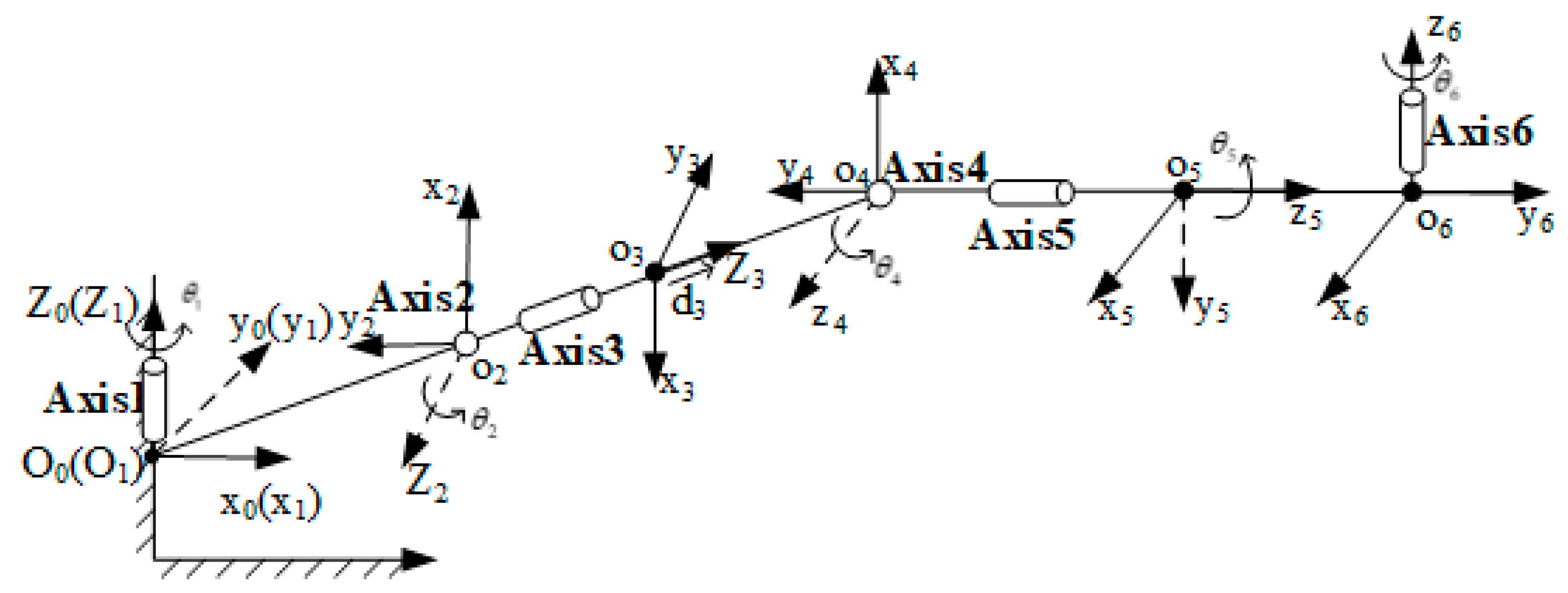
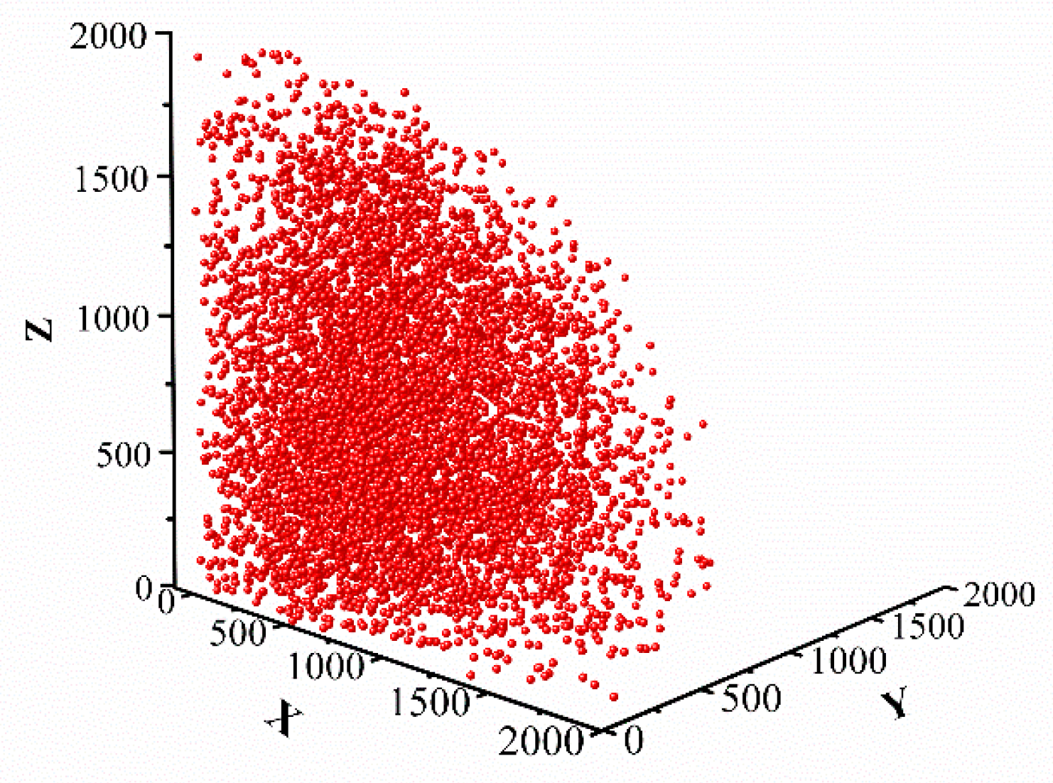
Section 3, the six-degree-of-freedom drilling arm of the drilling and anchoring robot is analyzed according to the modified DH (M-DH) solution method, the overall link coordinate system of the drilling arm is established, and the M-DH parameters of the drilling arm are finally determined according to the link coordinate system. A Monte Carlo random sampling method is used to calculate the reachable working space of the drill arm, and subsequent planning of the drill arm trajectory is carried out within the reachable working space. In the
Section 4, the principles and procedures of the RRT algorithm, the artificial potential field method, and the three-time B-sample curve fitting are described. In the
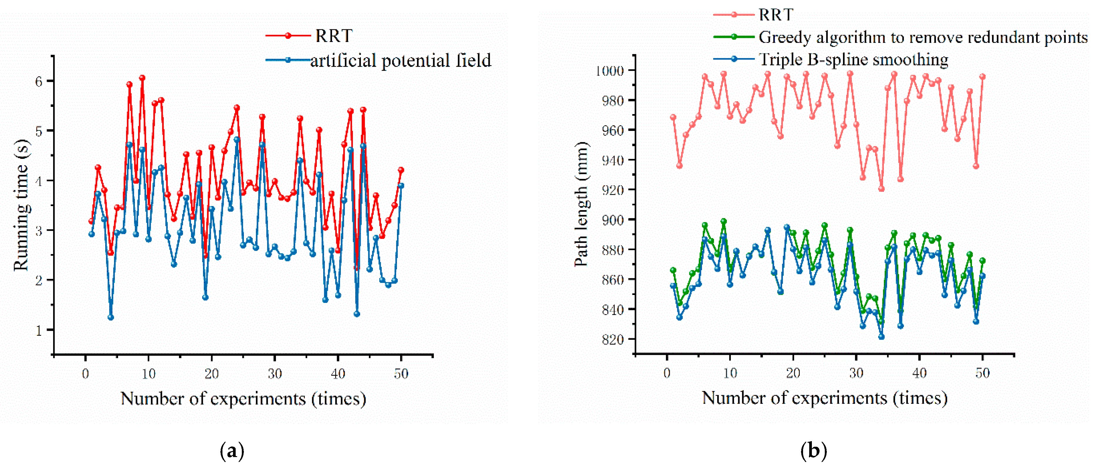
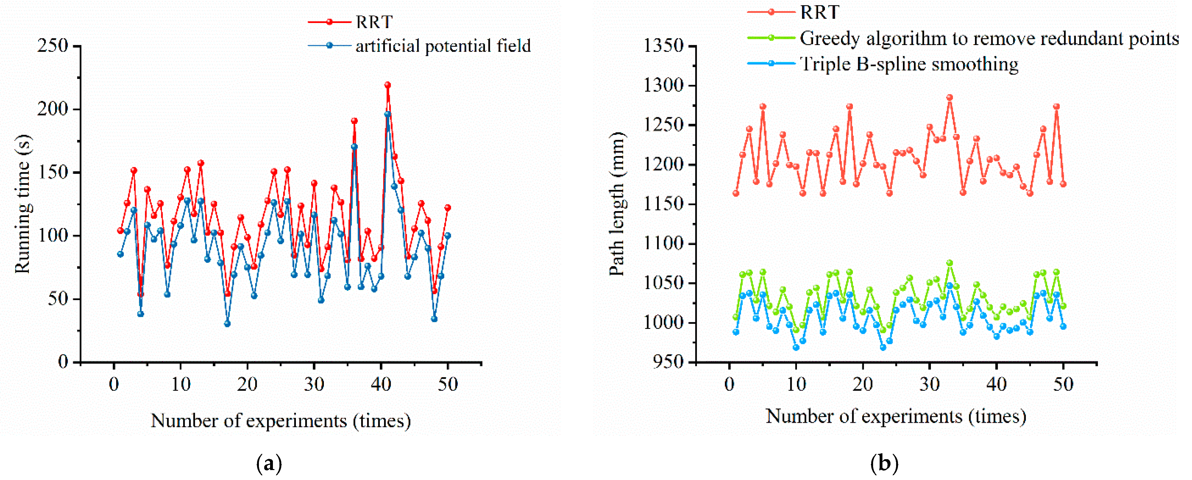
Section 5, simulation experiments are conducted in 2D and 3D maps to analyze and compare the difference in time consumption and path length between the RRT algorithm and the improved RRT algorithm. The results show that the improved RRT algorithm can effectively optimize the base path, improve path planning efficiency, enhance path smoothing, and shorten the path length. In the
Section 6, the feasibility and superiority of the improved RRT algorithm are summarized.
2. Overall Program for the Trajectory Planning of the Anchor Drilling Robot Drill Arm
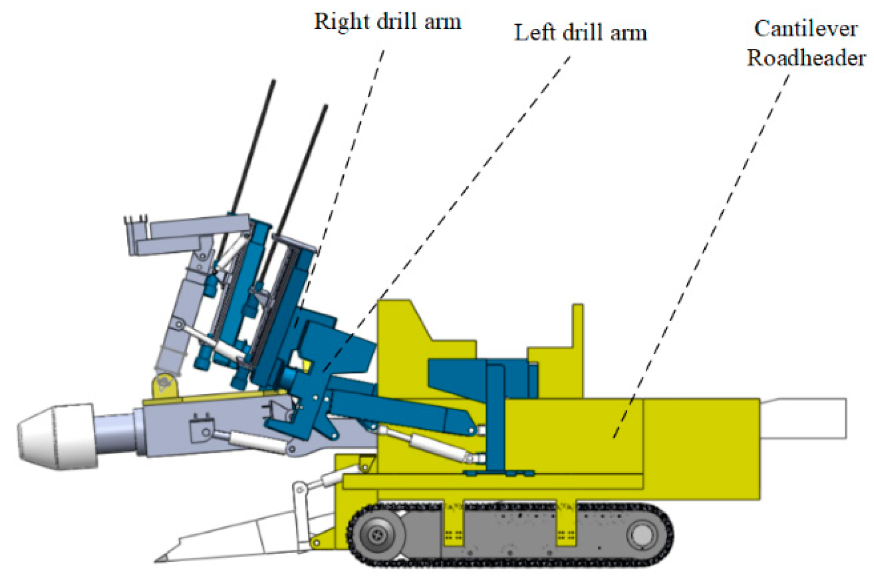
In this paper, the drilling arm of a drilling anchor robot is used as the object of study. Anchor drilling robots are essentially two six-degree-of-freedom robotic arms integrated into the body of a cantilevered road header. The basic structure of the anchor drilling robot is shown in
Figure 1. The cantilevered road header section is mainly used to cut the coal mine roadway, while the six-degree-of-freedom robotic arm section uses the drilling rig as its actuator to support the roadway.
The drilling arm mainly consists of the drilling machine, the swing mechanism, the telescopic mechanism, the cantilever mechanism, the slide seat mechanism, and the slide rail mechanism, as shown in
Figure 2.
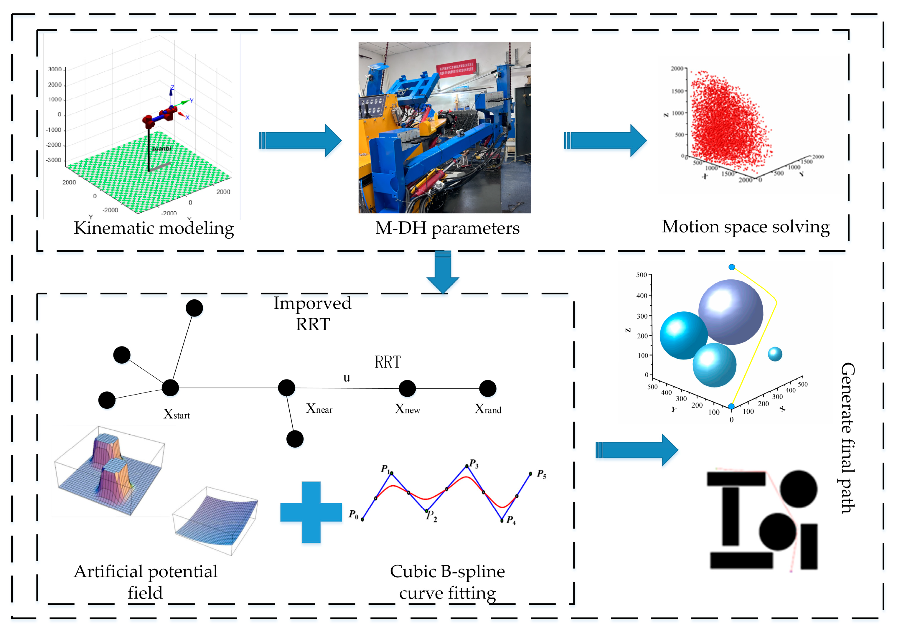
The working space of the anchor drilling robot is limited by the space in the underground coal mine tunnel, and at the same time, the environment in the working space is complex and variable during the drilling arm support process. Therefore, the trajectory planning process requires that information about the workspace environment and information about the feasible domain of the robotic arm be specified as the basis for planning, and the planning path must have real-time collision detection and dynamic planning capabilities to cope with the dynamically changing working environment. Therefore, the overall program of the drilling arm trajectory planning method of the drilling anchor robot based on the improved RRT algorithm in this paper is shown in
Figure 3.
Firstly, the kinematic model of the drilling arm is established; it is kinematically positive, and the DH solving parameters are solved, solving the drilling anchor module motion space using the Monte Carlo method and verifying that it meets the roadway support requirements. Secondly, a trajectory planning algorithm based on Rapidly Expanding Random Trees (RRTs, rapid-expanding random trees), by avoiding the need to model the space by performing collision detection on sampled points in the state space, is capable of efficiently solving path planning problems with high-dimensional spaces and complex constraints; it is also suitable for solving trajectory planning for multi-degree-of-freedom robots in complex and dynamic environments. The introduction of an artificial potential field factor into the algorithm can greatly improve search efficiency. At the same time, the path quality is improved by removing redundant points and smoothing and optimizing the path using a greedy algorithm and cubic B-sample curve fitting. This results in the realization of autonomous trajectory planning for the drilling arm of an underground coal mine anchor drilling robot.
4. Drill Arm Trajectory Planning Based on Improved RRT
4.1. RRT Algorithm
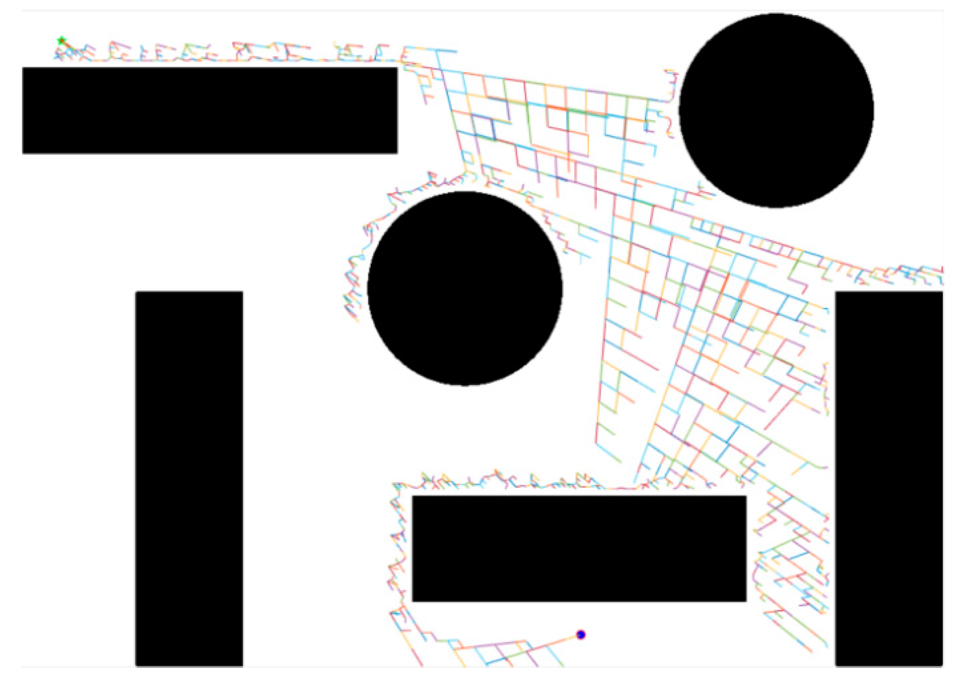
The traditional path planning algorithms are the artificial potential field method, the fuzzy rule method, the genetic algorithm, the neural network, and the ant colony optimization algorithm, among others. However, each of these methods requires the modeling of an obstacle in a defined space; the computational complexity is exponentially related to the robot’s degrees of freedom, so it is not suitable for solving the planning of multi-degree-of-freedom robots in complex environments. In the complex, dusty, and poorly illuminated environment of coal mines underground, a path planning algorithm based on Rapidly Expanding Random Trees (RRTs, rapid-expanding random trees) is characterized by its ability to search high-dimensional spaces quickly and efficiently by randomly sampling points in the state space and directing the search to blank regions to find a planned path from the start point to the goal point, which is suitable for solving the path planning of multi-degree-of-freedom robots in complex and dynamic environments; the algorithm has high coverage and a wide search range. The RRT algorithm generates a random tree through incremental, step-by-step iterations. The RRT algorithm node expansion process is shown in
Figure 7.
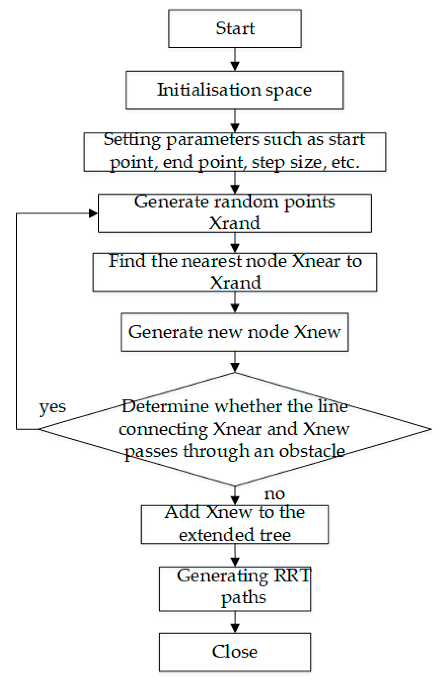
The specific steps of the RRT algorithm are shown in
Figure 8.
In the first step, the whole space is initialized, defining parameters such as the initial point, the end point, the number of sampling points, and the step size U between points. In the second step, a random point Xrand is generated in the space. In the third step, find the nearest point Xnear this random point in the set of points in the known tree. In the fourth step, intercept the point Xnew from Xnear in the direction of the line from Xnear to Xrand in step U. In the fifth step, determine if there is an obstacle between Xnear and Xnew, and if so, discard the point. In the sixth step, add new points to the tree collection. Cycle through steps two to six. Loop end condition: there is a new point within the set neighborhood of the end point.
In summary, the RRT algorithm generates random trees through incremental, step-by-step iterations and uses them to search for paths in high-dimensional spaces, avoiding spatially complex modeling and reducing computational costs. It is therefore suitable for solving the path planning problem of multi-degree-of-freedom robots in complex environments.
4.2. Improved RRT Algorithm
The algorithm flow shows that the RRT algorithm aims to find a path from the start point to the end point, starting from the beginning and keeping searching towards the end. But there are some drawbacks: The paths searched are not optimal and are inefficiently sampled throughout the space. The drawbacks of the RRT algorithm are especially obvious in the three-dimensional, spatially complex environment of the coal mines underground. The RRT algorithm can obtain a path from the start point to the end point in the complex environment of coal mines underground, but the path obtained has problems such as not being smooth and having a long generation time. This leads to low efficiency and poor path quality. In order to solve the above problems, an improved RRT algorithm is proposed.
4.2.1. Artificial Potential Field Method
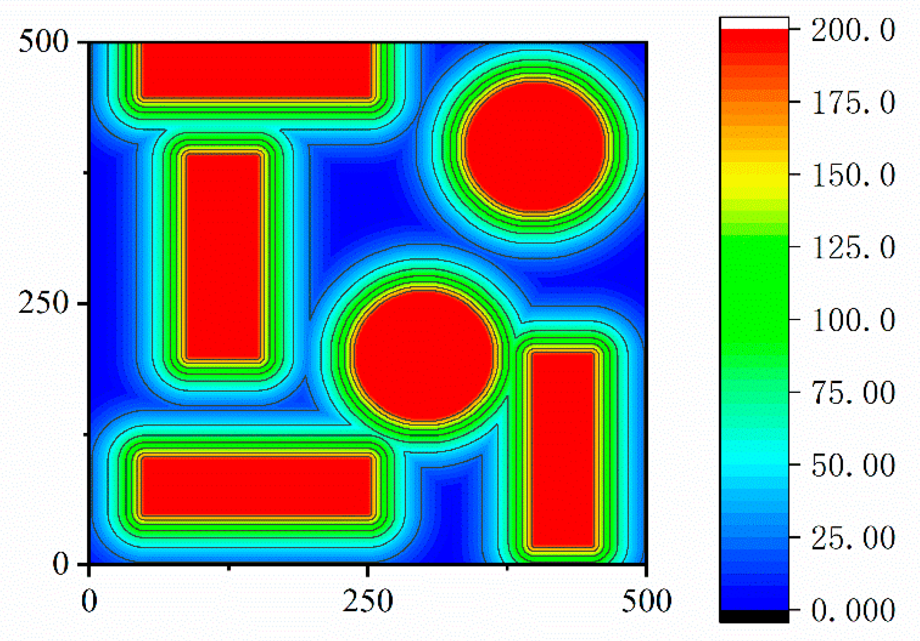
Firstly, to improve the efficiency of sampling and path generation, an artificial potential field factor is introduced. The potential field map is calculated for the entire known map by considering the target point location as the lowest point of the potential and the obstacles as the highest point of the potential. The gravitational potential field is mainly related to the distance between the end effector (drilling rig) and the drill hole at the target point. The greater the distance, the greater the potential energy value of the end effector (drilling rig). The smaller the distance, the smaller the potential energy value of the end effector (drilling rig), and the greater the potential energy value of the end effector (drilling rig):
where
is a scale factor indicator and
is the distance between the current state of the end effector (drilling rig) and the target. The factor that determines the obstacle’s repulsive potential field is the distance between the end effector (drilling rig) and the obstacle. When the end effector (drilling rig) does not enter the area of influence of the obstacle, it is subjected to a potential energy value of zero. The greater the distance between the end effector (drilling rig) and the obstacle after it enters the area of influence of the obstacle, the smaller the potential energy value of the end effector (drilling rig). The greater the potential energy value of the end effector (drilling rig) after it enters the area of influence of the obstacle, the smaller the distance and the greater the value of potential energy to which the end effector (drilling rig) is subjected. The potential field function of the repulsive potential field is given by:
The corresponding repulsive force is the negative gradient force of the repulsive potential field:
where
represents the distance between the object and the obstacle and
represents the radius of influence of each obstacle. Based on the gravitational field function and the repulsive field function defined above, a composite field can be obtained for the entire running space; the size of the combined potential field is the sum of the repulsive and gravitational potential fields. Therefore, the total function of the combined potential field is:
The combined force applied is:
The combined forces of gravity and repulsion guide the drill arm closer to the target point. The force analysis of the end effector is shown in
Figure 9.
Secondly, in order to solve the problem of unsmooth paths and poor quality, a greedy algorithm is introduced to remove redundant points from the paths, and three-time B-splines are used to post-process the smooth paths.
4.2.2. Redundant Point Rejection Based on Greedy Algorithm
The basic idea of the greedy algorithm is to develop a mathematical model to describe the problem, divide the problem to be solved into subproblems, solve each subproblem to obtain a locally optimal solution to the subproblem, and synthesize the locally optimal solutions of the subproblems into one solution of the original solution problem. The specific steps are as follows:
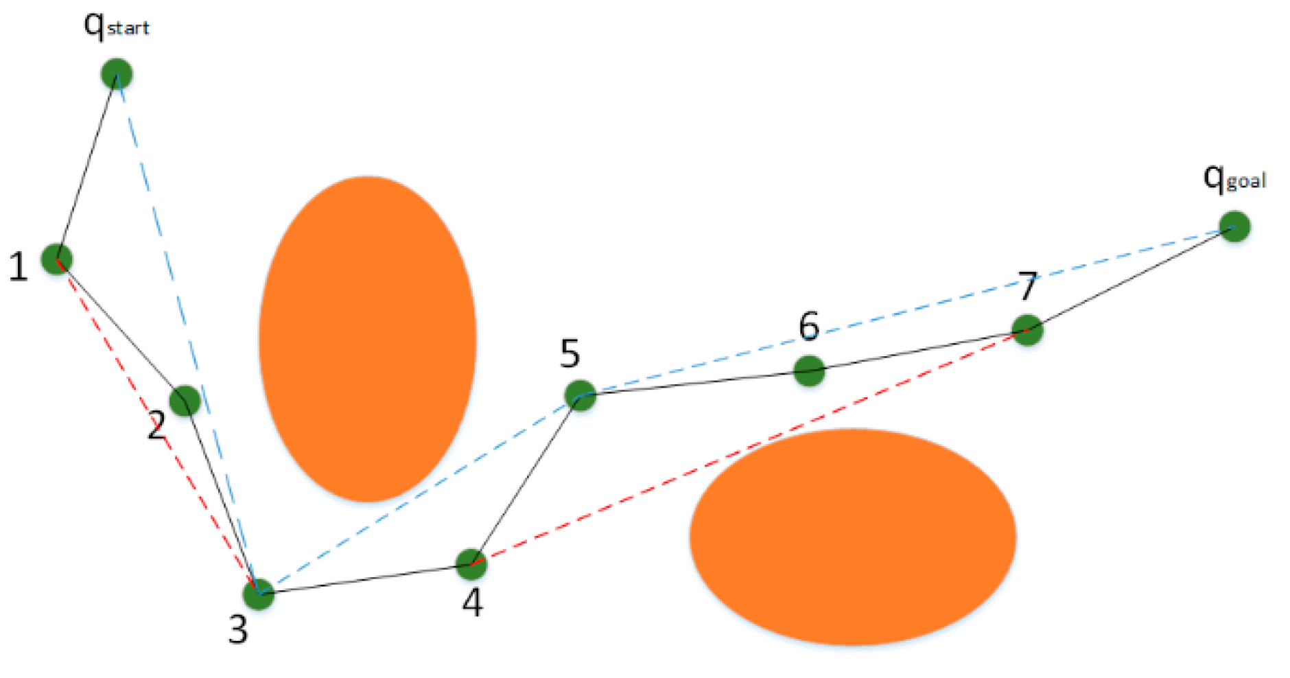
Firstly, the path starts at Xstart. Set a step size X to divide the path into segments according to the step size X. The X1 point is obtained by taking the distance of step X from the starting point. Connect the points Xstart and X1, and if there is no obstacle between them, then discard the X1 point. Then, connect Xstart with X2 and continue to repeat the above judgment operation. As shown in
Figure 10, the path between Xstart and X4 can be optimized as a segment. If there is an obstacle between the two, it means that the small section of the path is already the optimal path. Next, using X4 as a starting point, connect X4 to X5 and continue with the optimization steps. Finally, continue the cycle until all of the several points into which the path is divided have been run. The path obtained at this point will be shorter and more efficient than the initial path obtained by the RRT algorithm. The greedy algorithm removes the redundant points of the path as shown in
Figure 10. Among them, the orange circle represents the obstacle, 1–7 points represent the sampling point, the black line represents the original sampling path, and the blue and red lines represent two paths after removing redundant points from different angles.
4.2.3. Smoothing Paths Based on Cubic B-Splines
B-spline curves are a class of curves developed on the basis of Bezier curves that overcome the inconvenience caused by the overall controllability of the Bezier curve. Three planar discrete points determine a quadratic B-spline curve, and four planar discrete points determine a cubic B-spline curve. Bezier curves are irregular curves that require the construction of a mixture of interpolating polynomials between the start and endpoints; usually, an nth-degree polynomial is defined by n + 1 vertices and then given a position vector P(i-0,1,2,...n) of n + 1 points in space. The interpolation formula for the coordinates of the points on the Bezier parametric curve is:
where
is the characteristic point of the control curve and
is the K-order B-spline basis function. The basis functions in the cubic B-spline curve equation are:
where
denotes the factorial. Therefore, the cubic B-spline curve equation is:
Three planar discrete points determine a quadratic B-spline curve, and four planar discrete points determine a cubic B-spline curve.
The matrix form of the parametric expression for the cubic B-spline curve is given by:
Let the four discrete points be
,
,
, and
. Let the midpoint be
,
. The starting point S of the curve is on the center line
of the
,
points from
. The starting point E of the curve is on the center line
of the
,
points from
. The tangent to the start of the curve is parallel to
, and the tangent to the end is parallel to
. The principle of cubic B-spline fitting is shown in
Figure 11.
Introducing an artificial potential field factor into the map while optimizing the paths derived from the basic RRT algorithm based on the above greedy algorithm and cubic B-splines can increase the speed of path generation, reduce the length of the paths, and smooth the paths.
The artificial potential field factor and cubic B-spline curve fitting are introduced into the RRT algorithm. The next chapter introduces simulations and comparative analyses in the debugging software and prototype to verify the effectiveness of the improved algorithm.
6. Conclusions
When establishing the kinematic model of a drilling arm, the kinematic analysis of the intelligent drilling and anchor robot is the basis for optimal design and motion control, allowing the kinematic positive solution and M-DH solution parameters to be solved. The Monte Carlo method is used to solve the motion space of the drilling and anchor module to verify that it meets the requirements of roadway support.
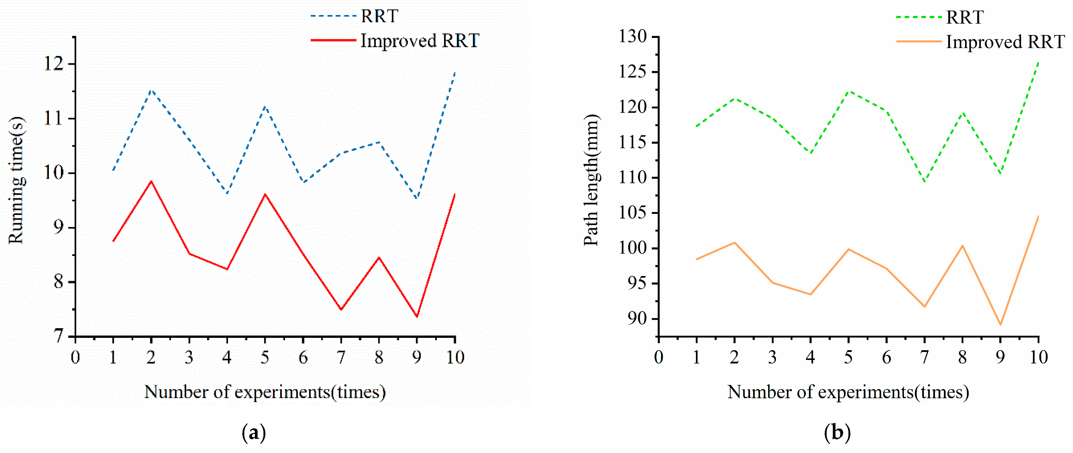
By introducing an artificial potential field factor, treating the target point location as the lowest point of potential energy and obstacles as the highest point of potential energy, and calculating the potential field map of the whole known map, the average speed of sampling and path generation is improved by 22%.
Aiming at the roughness of the path generated by the basic RRT algorithm, the greedy algorithm and the cubic B-spline are used to optimize the original path. The greedy algorithm is used to remove the redundant points, and the cubic B-spline is used to smooth the path; the average length of the path is reduced by 14% so as to improve the quality of the trajectory.
Through the comprehensive subjective and objective analysis of the kinematic modeling of the drilling and anchoring robot and the performance of the improved RRT algorithm, it is concluded that the improved RRT algorithm proposed in this paper for the trajectory planning of the drilling arm of the drilling and anchoring robot has strong robustness and real-time performance. The results show that the algorithm can provide high-quality and reliable information support for the tasks of trajectory planning and control of the drilling and anchoring robot.
