

Modeling and Application of an SMA-Actuated Lightweight Human-Inspired Gripper for Aerial Manipulation

 , , , and
Abstract
:1. Introduction
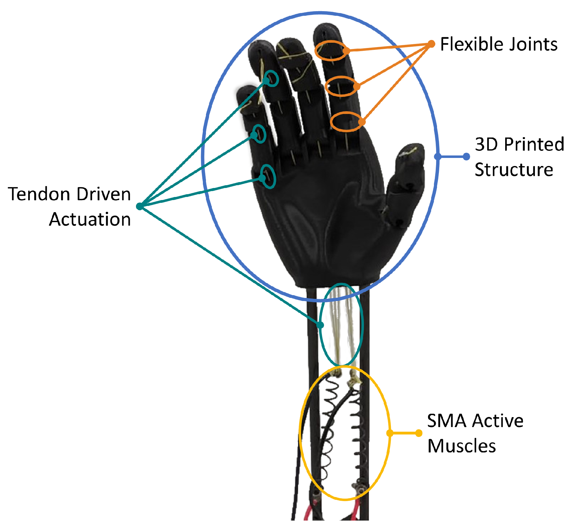
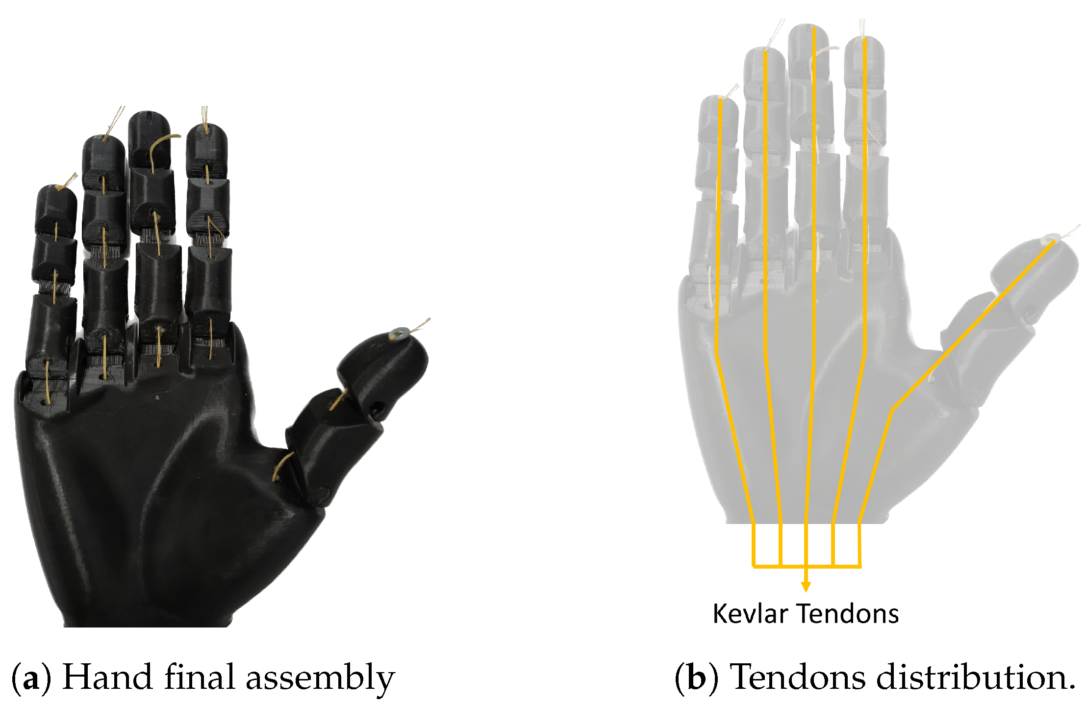
2. Multiple-Fingered Hand Design
2.1. Multiple-Fingered Hand
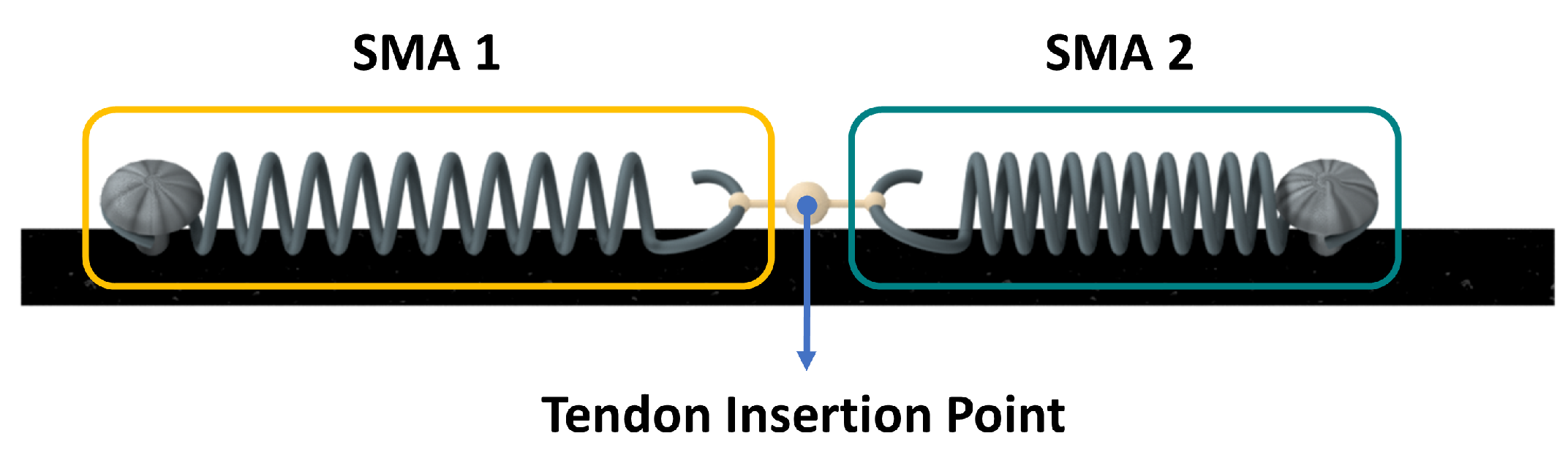
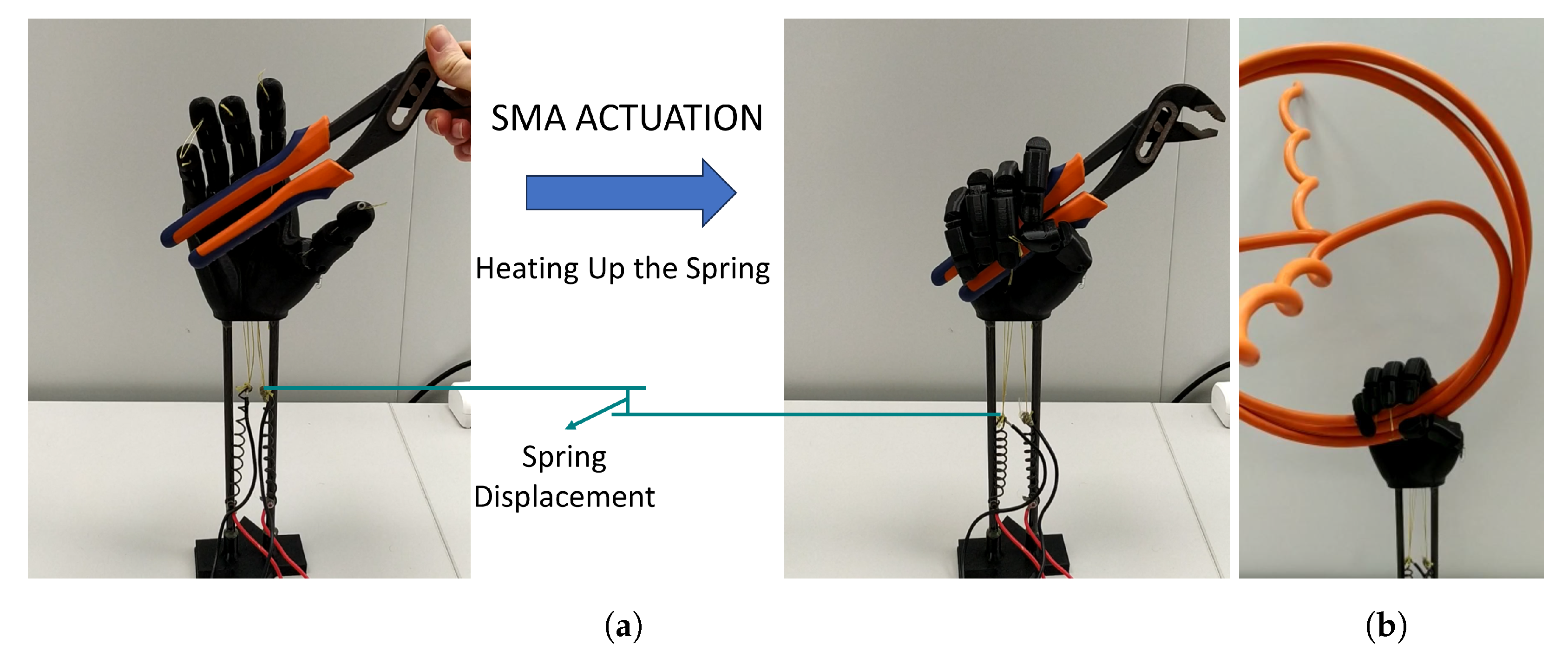
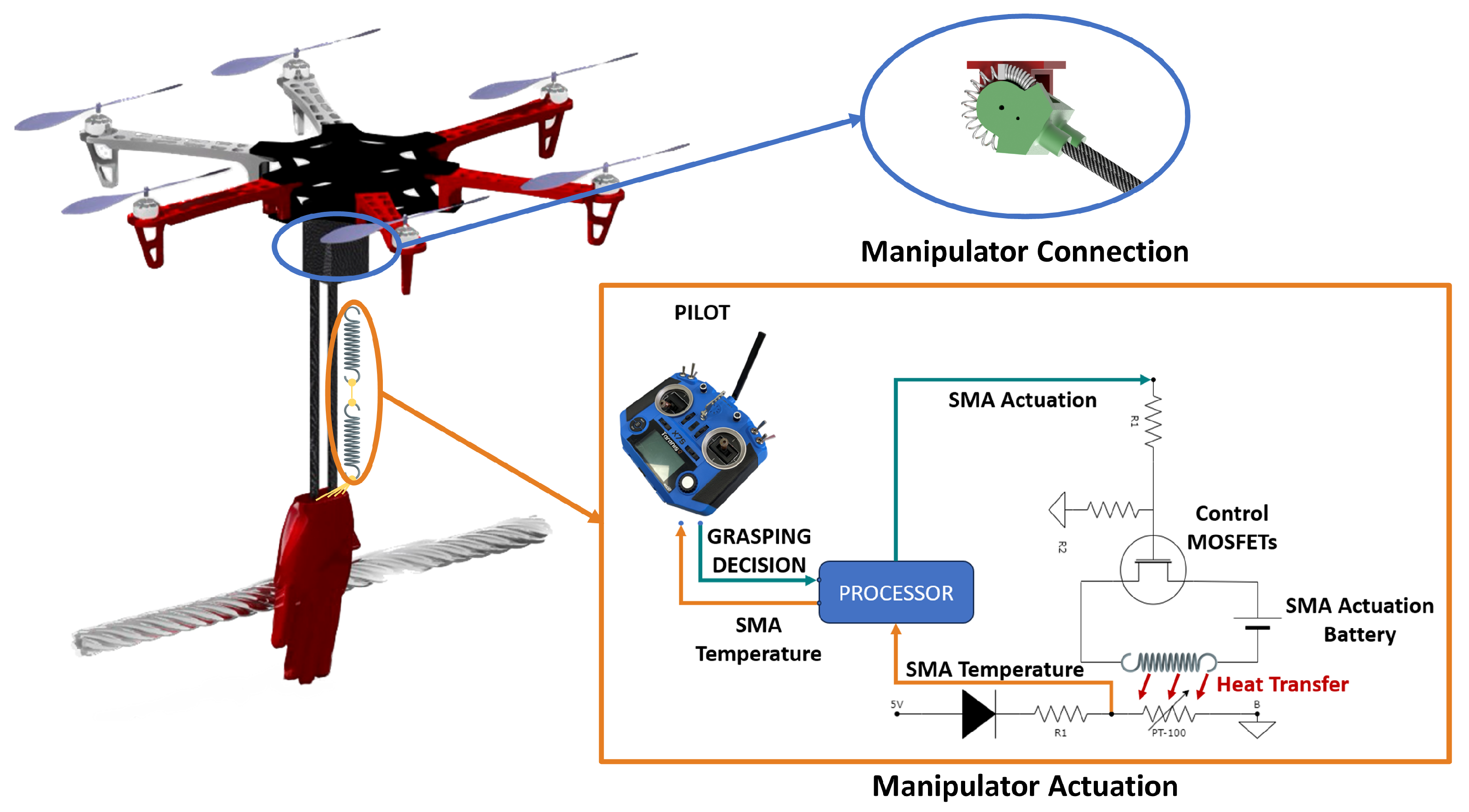
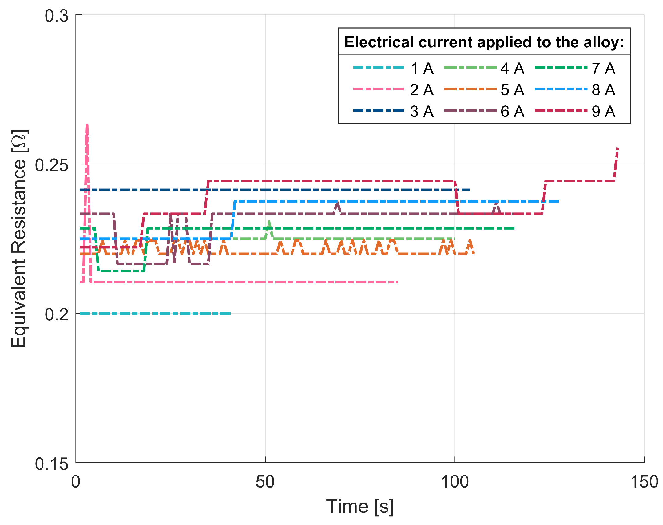
2.2. SMA Actuation
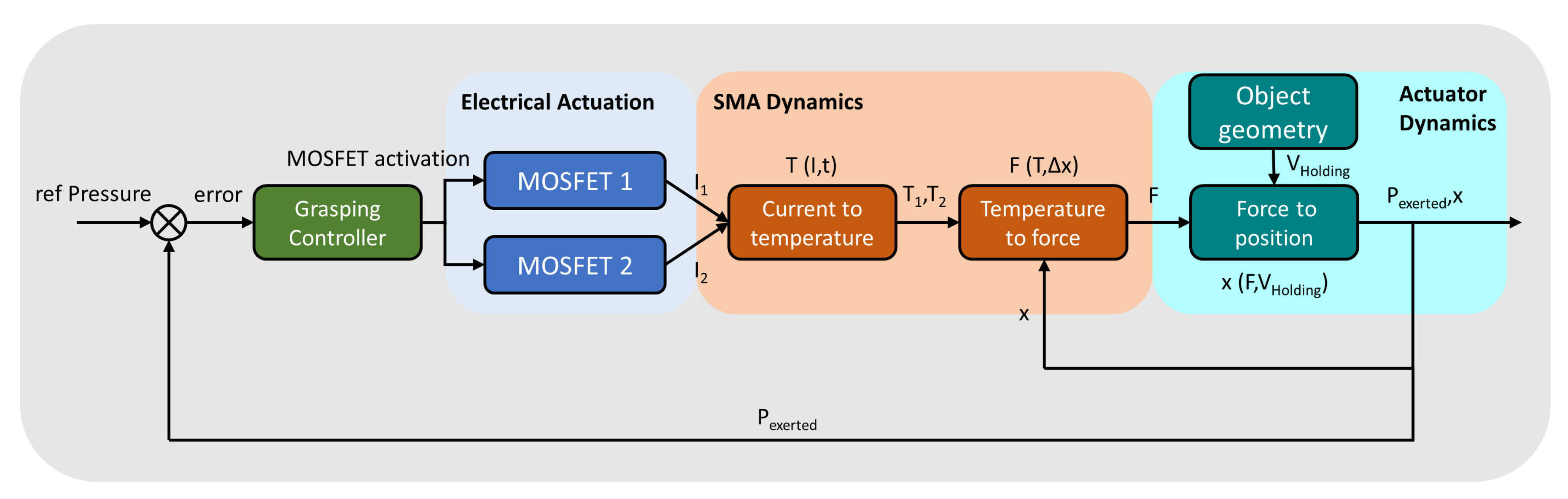
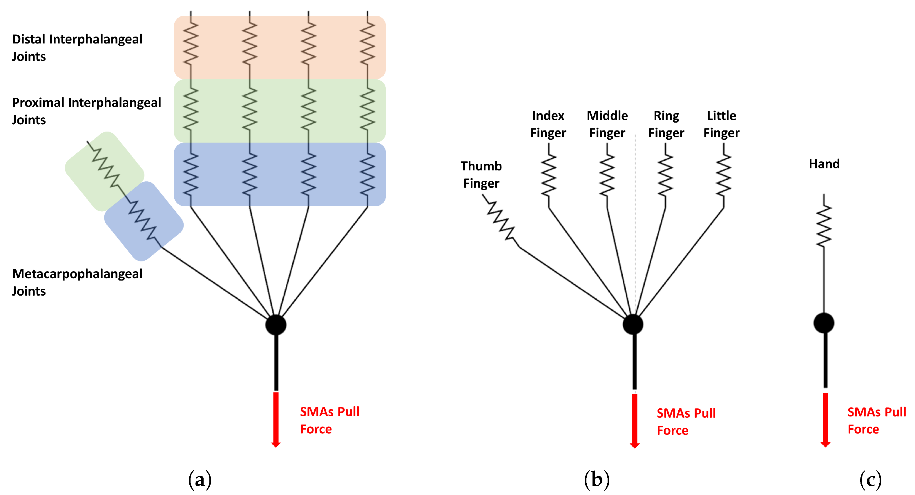
3. Dynamic Modeling
3.1. Hand Modeling
3.2. SMA Actuation Modeling
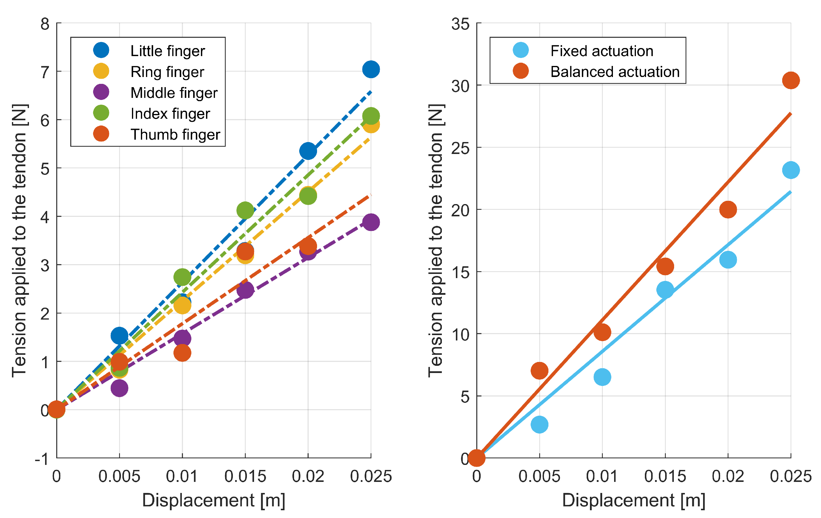
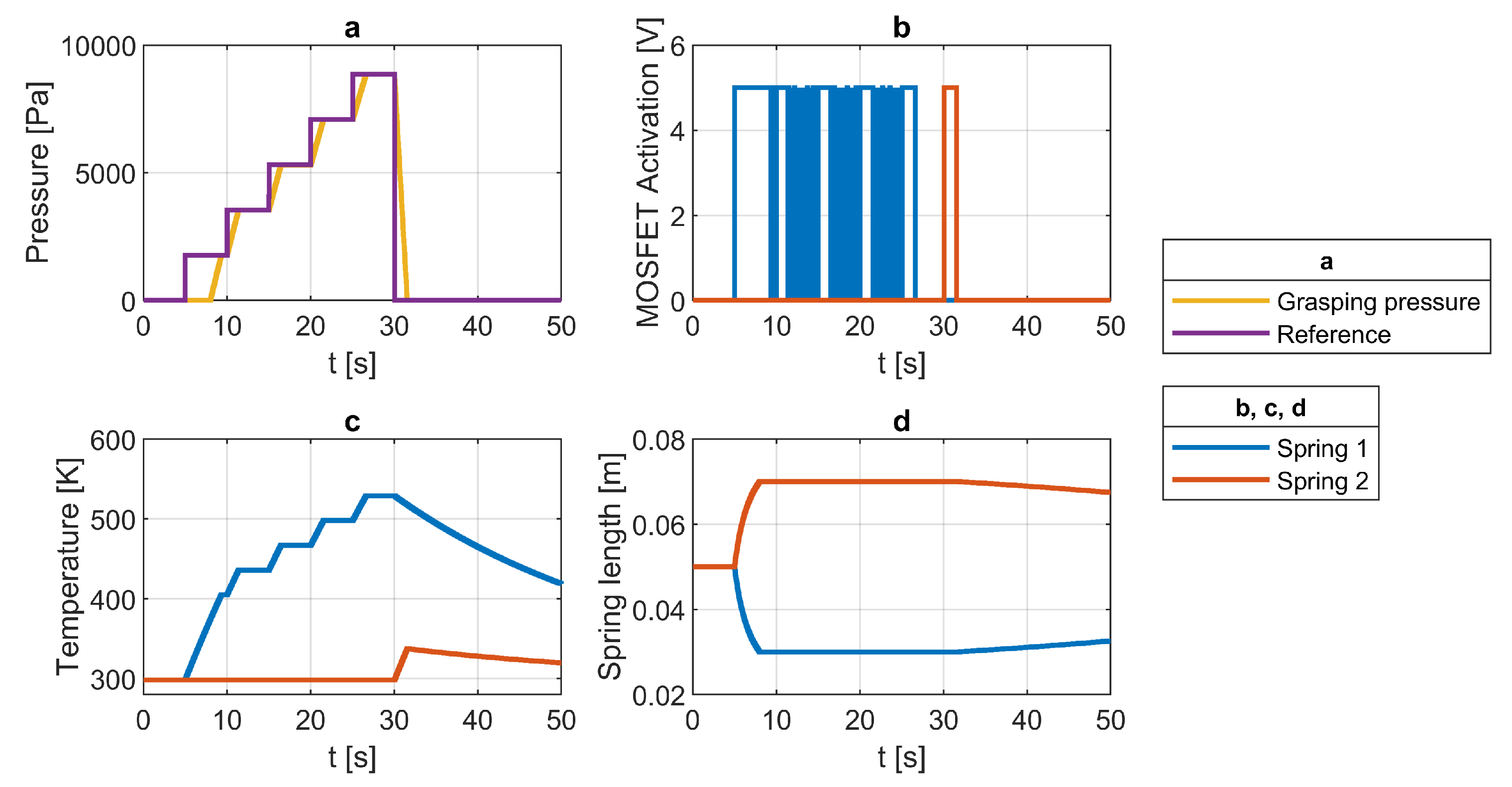
3.3. Modeling Results
4. Experimental Validation
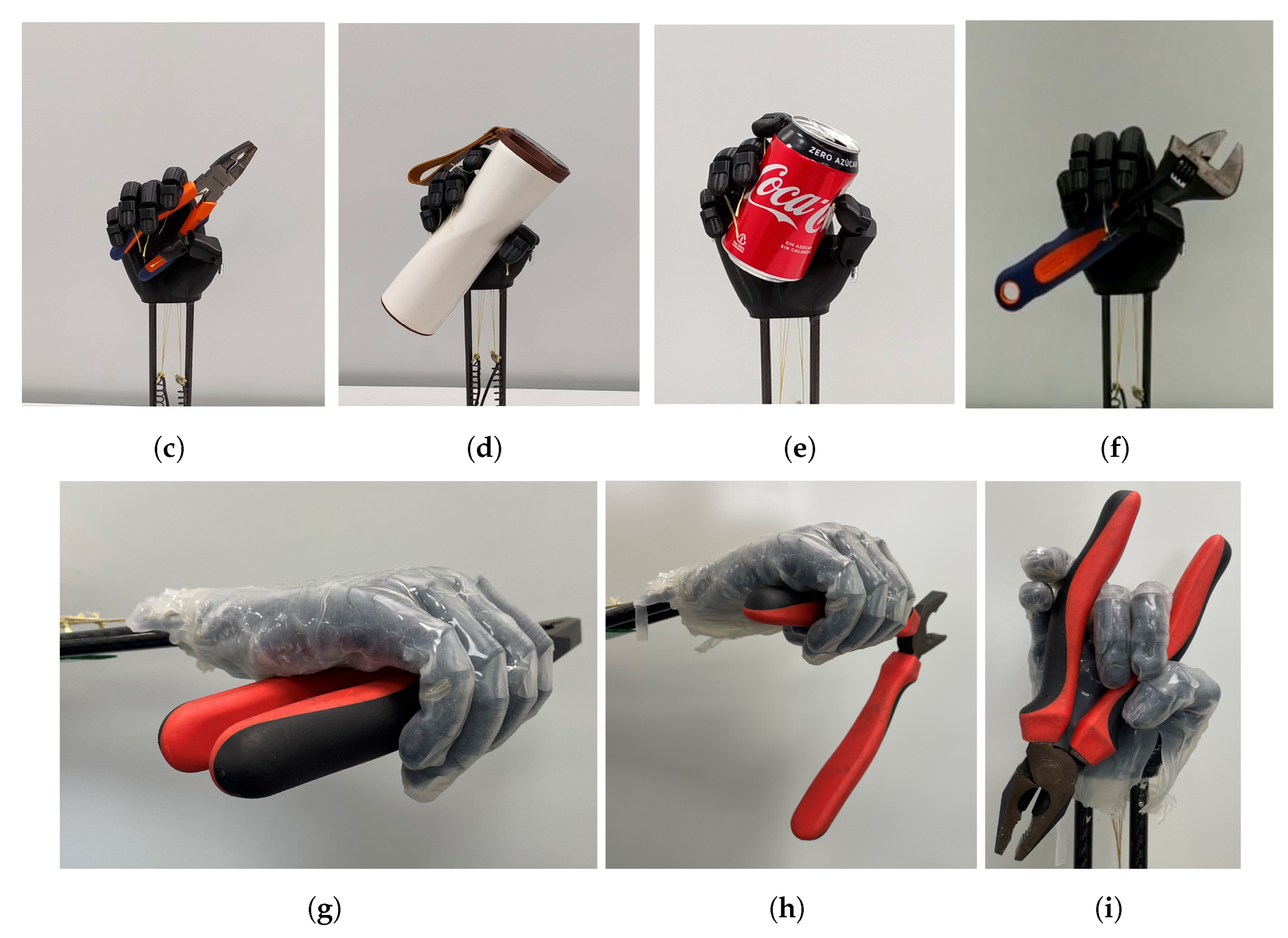
4.1. Grasping Experiments
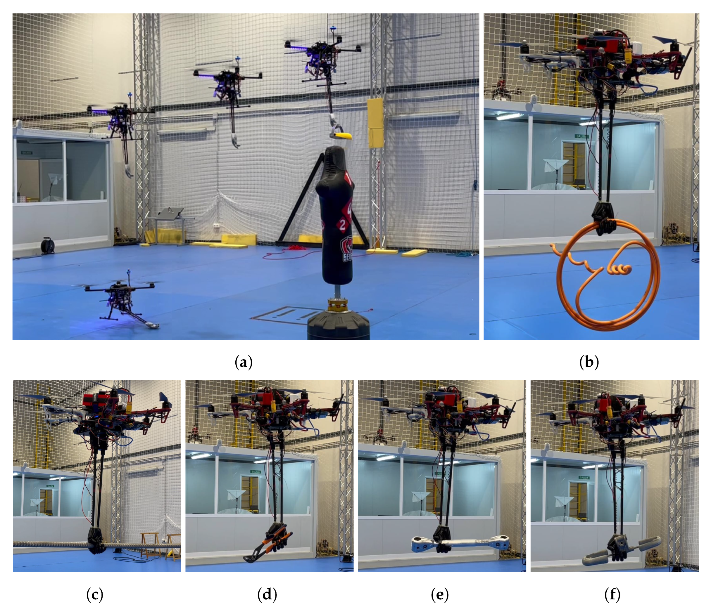
4.2. On-Flight Experiments
5. Conclusions
Author Contributions
Funding
Data Availability Statement
Acknowledgments
Conflicts of Interest
References
- Ilami, M.; Bagheri, H.; Ahmed, R.; Skowronek, E.O.; Marvi, H. Materials, Actuators, and Sensors for Soft Bioinspired Robots. Adv. Mater. 2021, 33, 2003139. [Google Scholar] [CrossRef] [PubMed]
- Liu, J.; Zhang, D.; Wu, C.; Tang, H.; Tian, C. A multi-finger robot system for adaptive landing gear and aerial manipulation. Robot. Auton. Syst. 2021, 146, 103878. [Google Scholar] [CrossRef]
- Zhao, Q.; Zhang, G.; Jafarnejadsani, H.; Wang, L. A modular continuum manipulator for aerial manipulation and perching. In Proceedings of the International Design Engineering Technical Conferences and Computers and Information in Engineering Conference, St. Louis, MO, USA, 14–17 August 2022; American Society of Mechanical Engineers: New York City, NY, USA, 2022; Volume 86281, p. V007T07A014. [Google Scholar]
- Rodriguez-Castaño, A.; Nekoo, S.R.; Romero, H.; Salmoral, R.; Acosta, J.Á.; Ollero, A. Installation of clip-type bird flight diverters on high-voltage power lines with aerial manipulation robot: Prototype and testbed experimentation. Appl. Sci. 2021, 11, 7427. [Google Scholar] [CrossRef]
- Cacace, J.; Giampetraglia, L.; Ruggiero, F.; Lippiello, V. A Novel Gripper Prototype for Helical Bird Diverter Manipulation. Drones 2023, 7, 60. [Google Scholar] [CrossRef]
- Miková, L.; Medvecká-Beňová, S.; Kelemen, M.; Trebuňa, F.; Virgala, I. Application of shape memory alloy (SMA) as actuator. Metalurgija 2015, 54, 169–172. [Google Scholar]
- Nespoli, A.; Besseghini, S.; Pittaccio, S.; Villa, E.; Viscuso, S. The high potential of shape memory alloys in developing miniature mechanical devices: A review on shape memory alloy mini-actuators. Sens. Actuators A Phys. 2010, 158, 149–160. [Google Scholar] [CrossRef]
- Gomez-Tamm, A.E.; Perez-Sanchez, V.; Arrue, B.C.; Ollero, A. SMA Actuated Low-Weight Bio-Inspired Claws for Grasping and Perching Using Flapping Wing Aerial Systems. In Proceedings of the 2020 IEEE/RSJ International Conference on Intelligent Robots and Systems (IROS), Las Vegas, NV, USA, 24 October 2020–24 January 2021; pp. 8807–8814. [Google Scholar]
- Ding, Q.; Chen, J.; Yan, W.; Yan, K.; Kyme, A.; Cheng, S.S. A High-Performance Modular SMA Actuator With Fast Heating and Active Cooling for Medical Robotics. IEEE/ASME Trans. Mechatronics 2022, 27, 5902–5913. [Google Scholar] [CrossRef]
- Niu, D.; Li, D.; Chen, J.; Zhang, M.; Lei, B.; Jiang, W.; Chen, J.; Liu, H. SMA-based soft actuators with electrically responsive and photoresponsive deformations applied in soft robots. Sens. Actuators A Phys. 2022, 341, 113516. [Google Scholar] [CrossRef]
- Yang, S.Y.; Kim, K.; Seo, S.; Shin, D.; Park, J.H.; Gong, Y.J.; Choi, H.R. Hybrid antagonistic system with coiled shape memory alloy and twisted and coiled polymer actuator for lightweight robotic arm. IEEE Robot. Autom. Lett. 2022, 7, 4496–4503. [Google Scholar] [CrossRef]
- Jeong, J.; Hyeon, K.; Jang, S.Y.; Chung, C.; Hussain, S.; Ahn, S.Y.; Bok, S.K.; Kyung, K.U. Soft wearable robot with shape memory alloy (SMA)-based artificial muscle for assisting with elbow flexion and forearm supination/pronation. IEEE Robot. Autom. Lett. 2022, 7, 6028–6035. [Google Scholar] [CrossRef]
- Dharmdas, A.; Patil, A.Y.; Baig, A.; Hosmani, O.Z.; Mathad, S.N.; Patil, M.B.; Kumar, R.; Kotturshettar, B.B.; Fattah, I.M.R. An Experimental and Simulation Study of the Active Camber Morphing Concept on Airfoils Using Bio-Inspired Structures. Biomimetics 2023, 8, 251. [Google Scholar] [CrossRef]
- Abbasi, S.; Mahmood, A.; Khaliq, A.; Imran, M. Reduced order modeling and simulation of a bio-inspired gust mitigating flapping wing UAV. Int. J. Intell. Robot. Appl. 2022, 6, 587–601. [Google Scholar] [CrossRef]
- Jini Raj, R.; Bruce Ralphin Rose, J.; Vasudevan, A. Analysis of Bio-inspired Fishbone Based Corrugated Rib for Adaptive Camber Morphing. J. Bionic Eng. 2023, 20, 1083–1102. [Google Scholar] [CrossRef]
- Perez-Sanchez, V.; Gomez-Tamm, A.E.; Savastano, E.; Arrue, B.C.; Ollero, A. Bio-Inspired Morphing Tail for Flapping-Wings Aerial Robots Using Macro Fiber Composites. Appl. Sci. 2021, 11, 2930. [Google Scholar] [CrossRef]
- Harvey, C.; de Croon, G.; Taylor, G.K.; Bomphrey, R.J. Lessons from natural flight for aviation: Then, now and tomorrow. J. Exp. Biol. 2023, 226, jeb245409. [Google Scholar] [CrossRef]
- Zhu, Z.; Zhao, J.; He, Y.; Guo, S.; Chen, S.; Ji, B. Aerodynamic analysis of insect-like flapping wings in fan-sweep and parallel motions with the slit effect. Biomim. Intell. Robot. 2022, 2, 100046. [Google Scholar] [CrossRef]
- Nekoo, S.R.; Acosta, J.; Ollero, A. Combination of terminal sliding mode and finite-time state-dependent Riccati equation: Flapping-wing flying robot control. Proc. Inst. Mech. Eng. Part I J. Syst. Control Eng. 2023, 237, 870–887. [Google Scholar] [CrossRef]
- Azargoon, Y.; Djavareshkian, M.H. Unsteady aerodynamics of flapping bionic eagle wings in forward flight: An experimental and numerical study. Proc. Inst. Mech. Eng. Part C J. Mech. Eng. Sci. 2023, 237, 2090–2107. [Google Scholar] [CrossRef]
- Li, D.; Zhao, S.; Da Ronch, A.; Xiang, J.; Drofelnik, J.; Li, Y.; Zhang, L.; Wu, Y.; Kintscher, M.; Monner, H.P.; et al. A review of modelling and analysis of morphing wings. Prog. Aerosp. Sci. 2018, 100, 46–62. [Google Scholar] [CrossRef]
- Han, J.H.; Lee, J.S.; Kim, D.K. Bio-inspired flapping UAV design: A university perspective. In Proceedings of the Health Monitoring of Structural and Biological Systems 2009, SPIE, San Diego, CA, USA, 8–12 March 2009; Volume 7295, pp. 466–477. [Google Scholar]
- Mannam, N.P.; Duba, P.K.; Sharma, D. Future of Planetary Exploration: Bioinspired Drones for Low Density Martian Atmosphere. In Proceedings of the AIAA SCITECH 2023 Forum, Orlando, FL, USA, 8–12 January 2023; p. 1421. [Google Scholar]
- Afakh, M.L.; Sato, H.; Takesue, N. A Study towards a Flapping Robot Maintaining Attitude during Gliding. Int. J. Adv. Sci. Eng. Inf. Technol. 2023, 13, 681–687. [Google Scholar] [CrossRef]
- Nekoo, S.R.; Feliu-Talegon, D.; Acosta, J.A.; Ollero, A. A 79.7 g Manipulator Prototype for E-Flap Robot: A Plucking-Leaf Application. IEEE Access 2022, 10, 65300–65308. [Google Scholar] [CrossRef]
- de Croon, G. Flapping wing drones show off their skills. Sci. Robot. 2020, 5, eabd0233. [Google Scholar] [CrossRef] [PubMed]
- Bao, C.; Kim, T.H.; Kalhori, A.H.; Kim, W.S. A 3D-printed neuromorphic humanoid hand for grasping unknown objects. Iscience 2022, 25, 104119. [Google Scholar] [CrossRef]
- De Pascali, C.; Naselli, G.A.; Palagi, S.; Scharff, R.B.; Mazzolai, B. 3D-printed biomimetic artificial muscles using soft actuators that contract and elongate. Sci. Robot. 2022, 7, eabn4155. [Google Scholar] [CrossRef] [PubMed]
- Wang, C.; Liu, Y.; Qu, X.; Shi, B.; Zheng, Q.; Lin, X.; Chao, S.; Wang, C.; Zhou, J.; Sun, Y.; et al. Ultra-stretchable and fast self-healing ionic hydrogel in cryogenic environments for artificial nerve fiber. Adv. Mater. 2022, 34, 2105416. [Google Scholar] [CrossRef]
- Zhou, H.; Tawk, C.; Alici, G. A 3D printed soft robotic hand with embedded soft sensors for direct transition between hand gestures and improved grasping quality and diversity. IEEE Trans. Neural Syst. Rehabil. Eng. 2022, 30, 550–558. [Google Scholar] [CrossRef]
- Abd, M.A.; Ingicco, J.; Hutchinson, D.T.; Tognoli, E.; Engeberg, E.D. Multichannel haptic feedback unlocks prosthetic hand dexterity. Sci. Rep. 2022, 12, 2323. [Google Scholar] [CrossRef]
- D’Angelo, S.; Pagano, F.; Ruggiero, F.; Lippiello, V. Development of a Control Framework to Autonomously Install Clip Bird Diverters on High-Voltage Lines. In Proceedings of the 2023 International Conference on Unmanned Aircraft Systems (ICUAS), Warsaw, Poland, 6–9 June 2023; pp. 377–382. [Google Scholar]
- De La Zerda, S.; Rosselli, L. Mitigating collision of birds against transmission lines in wetland areas in Columbia by marking the ground wire with bird flight diverters (BFD). In Environmental Concerns in Rights-Of-Way Management; Elsevier: Amsterdam, The Netherlands, 2002; pp. 395–402. [Google Scholar]
- Liang, C.; Rogers, C. Design of shape memory alloy springs with applications in vibration control. J. Vib. Acoust. 1993, 115, 129–135. [Google Scholar] [CrossRef]
- Kim, S.; Hawkes, E.; Choy, K.; Joldaz, M.; Foleyz, J.; Wood, R. Micro artificial muscle fiber using NiTi spring for soft robotics. In Proceedings of the 2009 IEEE/RSJ International Conference on Intelligent Robots and Systems, St. Louis, MO, USA, 10–15 October 2009; pp. 2228–2234. [Google Scholar]
- Chauhan, A.; Patel, S.; Vaish, R.; Bowen, C.R. A review and analysis of the elasto-caloric effect for solid-state refrigeration devices: Challenges and opportunities. MRS Energy Sustain. 2015, 2, E16. [Google Scholar] [CrossRef]
- Shintake, J.; Cacucciolo, V.; Floreano, D.; Shea, H. Soft Robotic Grippers. Adv. Mater. 2018, 30, 1707035. [Google Scholar] [CrossRef]
- Pounds, P.E.; Dollar, A. Hovering stability of helicopters with elastic constraints. In Proceedings of the Dynamic Systems and Control Conference, Nara, Japan, 12–15 September 2010; Volume 44182, pp. 781–788. [Google Scholar]
- Doyle, C.E.; Bird, J.J.; Isom, T.A.; Kallman, J.C.; Bareiss, D.F.; Dunlop, D.J.; King, R.J.; Abbott, J.J.; Minor, M.A. An Avian-Inspired Passive Mechanism for Quadrotor Perching. IEEE/ASME Trans. Mechatronics 2013, 18, 506–517. [Google Scholar] [CrossRef]
- Roderick, W.R.; Cutkosky, M.R.; Lentink, D. Bird-inspired dynamic grasping and perching in arboreal environments. Sci. Robot. 2021, 6, eabj7562. [Google Scholar] [CrossRef] [PubMed]
- Kim, S.; Choi, S.; Kim, H.J. Aerial manipulation using a quadrotor with a two DOF robotic arm. In Proceedings of the 2013 IEEE/RSJ International Conference on Intelligent Robots and Systems, Tokyo, Japan, 3–7 November 2013; pp. 4990–4995. [Google Scholar]
- Zhang, H.; Sun, J.; Zhao, J. Compliant Bistable Gripper for Aerial Perching and Grasping. In Proceedings of the 2019 International Conference on Robotics and Automation (ICRA), Montreal, QC, Canada, 20–24 May 2019; pp. 1248–1253. [Google Scholar]
- Fiaz, U.A.; Abdelkader, M.; Shamma, J.S. An Intelligent Gripper Design for Autonomous Aerial Transport with Passive Magnetic Grasping and Dual-Impulsive Release. In Proceedings of the 2018 IEEE/ASME International Conference on Advanced Intelligent Mechatronics (AIM), Auckland, New Zealand, 9–12 July 2018; pp. 1027–1032. [Google Scholar]
- Yu, P.; Wang, Z.; Wong, K. Exploring aerial perching and grasping with dual symmetric manipulators and compliant end-effectors. Int. J. Micro Air Veh. 2019, 11, 1756829319877416. [Google Scholar] [CrossRef]


| Electrical Current [A] | Instant Consumed Power [W] | Time [s] | Temperature [K] | Consumed Energy [J] |
|---|---|---|---|---|
| 1 | 0.2 | 21 | 296.9 | 4.2 |
| 2 | 0.76 | 72 | 303 | 54.8 |
| 3 | 2.03 | 93 | 313.9 | 188.8 |
| 4 | 3.6 | 91 | 328.4 | 327.8 |
| 5 | 5.5 | 89 | 341.7 | 487.8 |
| 6 | 8.3 | 103 | 363.5 | 853.1 |
| 7 | 11.2 | 112 | 380.5 | 1245.3 |
| 8 | 14.9 | 117 | 401.1 | 1745.2 |
| 9 | 19.33 | 140 | 437.8 | 2704.6 |
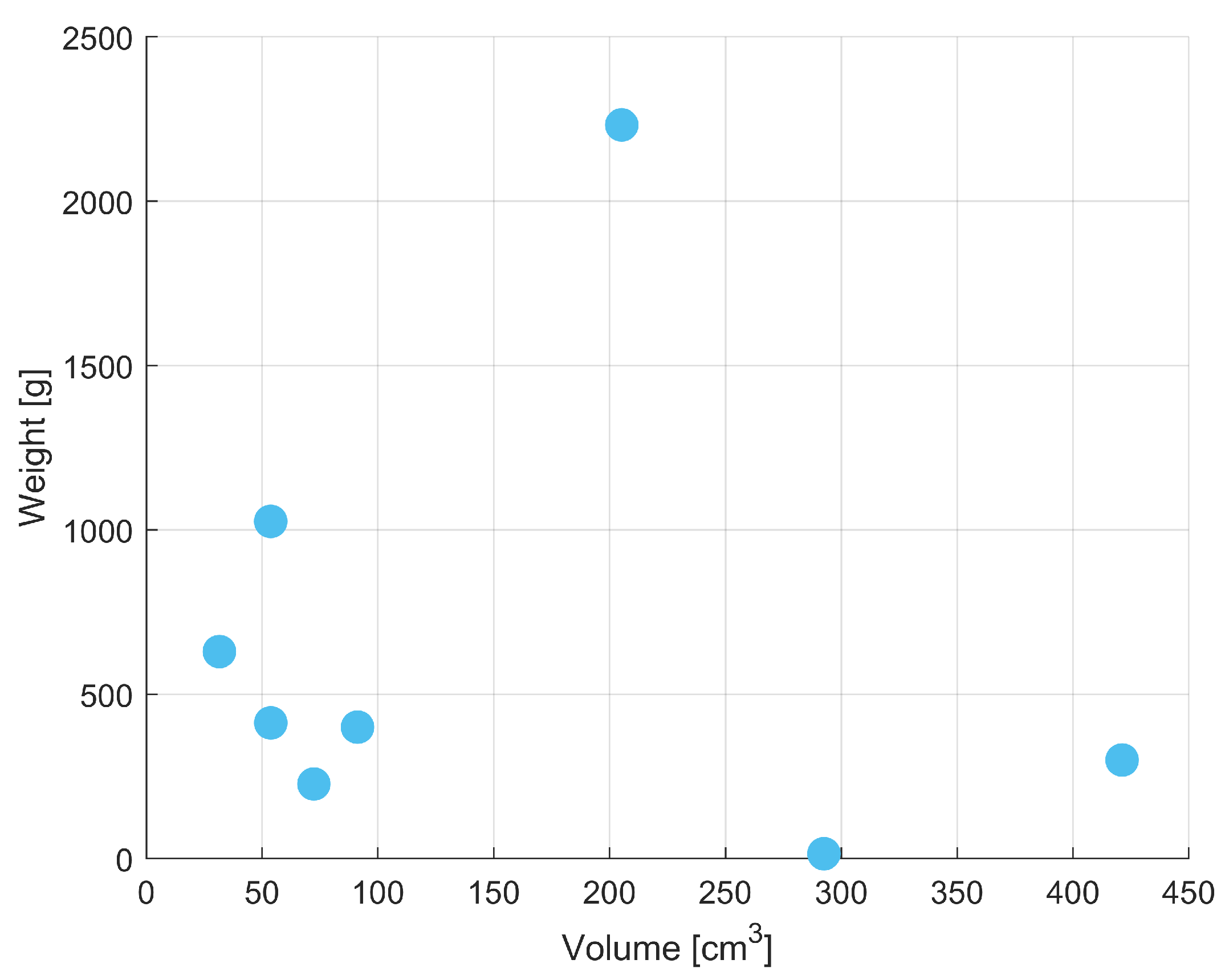
| Object | Weight [g] | Grasping Volume [cm3] |
|---|---|---|
| Slip joint plier | 453 | 91.2 |
| Power line bird diverter | 630 | 31.6 |
| Diagonal plier | 227.1 | 72.35 |
| Thermal bottle | 300 | 421.2 |
| Soft drink can | 15 | 292.5 |
| Adjustable wrench | 413 | 53.75 |
| Power line phase separator | 1026 | 53.72 |
| Stockbridge damper | 2232 | 205.2 |
| Gripper | System Weight [g] | Maximun load [kg] | Load/Weight | Actuation Method | Actuators | Adaptability | Soft Contact |
|---|---|---|---|---|---|---|---|
| Four finger gripper [38] | - | 1 | - | Tendon driven | Servos | Low (Cylindrical shapes) | No |
| Underactuated gripping foot [39] | 478 | - | - | Tendon driven | Passive | Low (Cylindrical shapes) | Yes |
| Bird inspired claws [40] | 250 | 0.1 | 0.4 | Tendon driven | Springs and servos | Medium (Soft objects) | No |
| Robotic arm manipulator [41] | 900 | 0.45 | 0.5 | Mechanical | Servos | Low (Plain surfaces) | No |
| Compliant bistable gripper [42] | 9 | 0.027 | 3 | Bistable system | Passive | Not applicable | Yes |
| Magnetic gripper [43] | 295 | 2.6 | 8.81 | Magnetic | Magnets and Servos | Not applicable | No |
| Dual symmetric manipulator [44] | 330 | 0.4 | 1.21 | Mechanical | Servos | Low (Plain surfaces) | No |
| SMA bird inspired claws [8] | 180 | 0.25 | 1.4 | Tendon driven | SMAs | Medium (Soft objects) | Yes |
| Anthropomorphic hand | 225 | 3 | 13.33 | Tendon driven | SMAs | High (Multiple geometries) | Yes |
Disclaimer/Publisher’s Note: The statements, opinions and data contained in all publications are solely those of the individual author(s) and contributor(s) and not of MDPI and/or the editor(s). MDPI and/or the editor(s) disclaim responsibility for any injury to people or property resulting from any ideas, methods, instructions or products referred to in the content. |
© 2023 by the authors. Licensee MDPI, Basel, Switzerland. This article is an open access article distributed under the terms and conditions of the Creative Commons Attribution (CC BY) license (https://creativecommons.org/licenses/by/4.0/).
Share and Cite
Perez-Sanchez, V.; Garcia-Rubiales, F.J.; Nekoo, S.R.; Arrue, B.; Ollero, A. Modeling and Application of an SMA-Actuated Lightweight Human-Inspired Gripper for Aerial Manipulation. Machines 2023, 11, 859. https://doi.org/10.3390/machines11090859
Perez-Sanchez V, Garcia-Rubiales FJ, Nekoo SR, Arrue B, Ollero A. Modeling and Application of an SMA-Actuated Lightweight Human-Inspired Gripper for Aerial Manipulation. Machines. 2023; 11(9):859. https://doi.org/10.3390/machines11090859
Chicago/Turabian StylePerez-Sanchez, Vicente, Francisco Javier Garcia-Rubiales, Saeed Rafee Nekoo, Begoña Arrue, and Anibal Ollero. 2023. "Modeling and Application of an SMA-Actuated Lightweight Human-Inspired Gripper for Aerial Manipulation" Machines 11, no. 9: 859. https://doi.org/10.3390/machines11090859
APA StylePerez-Sanchez, V., Garcia-Rubiales, F. J., Nekoo, S. R., Arrue, B., & Ollero, A. (2023). Modeling and Application of an SMA-Actuated Lightweight Human-Inspired Gripper for Aerial Manipulation. Machines, 11(9), 859. https://doi.org/10.3390/machines11090859