Article

Research on Lateral Maneuverability of a Supercavitating Vehicle Based on RBFNN Adaptive Sliding Mode Control with Rolling Restriction and Planing Force Avoidance

College of Weapon Engineering, Naval University of Engineering, Wuhan 430033, China
*
Author to whom correspondence should be addressed.
Machines 2023, 11(8), 845; https://doi.org/10.3390/machines11080845
Submission received: 11 June 2023 / Revised: 19 July 2023 / Accepted: 21 July 2023 / Published: 19 August 2023
(This article belongs to the Topic Vehicle Dynamics and Control)

Abstract

:
This paper addresses the lateral motion control of a supercavitating vehicle and studies its ability to maneuver. According to the unique hydrodynamic characteristics of the supercavitating vehicle, highly coupled nonlinear 6-degree-of-freedom (DOF) dynamic and kinematic models are constructed considering time-delay effects. A control scheme utilizing radial basis function (RBF) neural-network-(NN)-based adaptive sliding with planing force avoidance is proposed to simultaneously control the longitudinal stability and lateral motion of the supercavitating vehicle in the presence of external ocean-induced disturbances. The online estimation of nonlinear disturbances is conducted in real time by the designed NN and compensated for the dynamic control laws. The adaptive laws of the NN weights and control parameters are introduced to improve the performance of the NN. The least squares method is utilized to solve the actuator control efforts with rolling restriction in real-time online. Rigorous theoretical proofs based on the Lyapunov theory prove the globally asymptotic stability of the proposed controller. Finally, numerical simulations were performed to obtain maximum maneuverability and verify the effectiveness and robustness of the proposed control scheme.

1. Introduction

In the past few decades, underwater vehicles have been widely used for various underwater tasks [1]. With the continuous development of supercavitating technology, the speed of an underwater vehicle has increased tremendously by generating a supercavity to envelop the vehicle, which is called the supercavitating vehicle. Due to the existence of the supercavity, most regions of the supercavitating vehicle do not contact the surrounding flow field so as to dramatically reduce the skin friction drag, which allows for high speeds in comparison to a conventional underwater vehicle [2,3]. The hydrodynamic performance of a supercavitating vehicle is significantly different from that of a conventional underwater vehicle due to the nonlinear interaction and penetration between the vehicle body and supercavity. Additionally, the reduction in the wetted surface area cannot guarantee the stability of a supercavitating vehicle by relying solely on the tail fins. Generally, a cavitator and tail fins are required together as actuators to control the motion of a supercavitating vehicle. Therefore, the motion control and maneuverability of a supercavitating vehicle present severe challenges [2].
Studying the lateral motion control of a supercavitating vehicle is under the premise of satisfying longitudinal stability, and most of the previous research studies on supercavitating vehicles have focused on the design of a longitudinal motion controller design. In a previous study [4], the longitudinal dynamic model of a supercavitating vehicle was derived, which was adopted by many subsequent relevant studies. However, this model did not take the cavity memory effect into consideration. Linear feedback control and switching control were presented to stabilize the dive-plane dynamics of a supercavitating vehicle at the desired equilibrium point [5]. Based on a 3-DOF hydrodynamic model considering memory effects, the paper [3] designed a model predictive controller to track pitch angle, angular rate, vertical position, and vertical speed. In literature [6], a supercavitating vehicle model was simplified into a linear time-invariant system, and signal weighted H optimization was adopted to design the controller’s tracking pitch command with planing force avoidance. The authors [7] constructed linear parameter-varying models of a supercavitating vehicle and supercavity, and the proposed controller could solve linear matrix inequalities to obtain the optimal state feedback control law. A cascade control scheme for a supercavitating vehicle in the longitudinal plane was proposed. The position and attitude were controlled by the backstepping control method. Meanwhile, a boundary sliding mode controller was designed to regulate the vertical velocity and pitch rate [8]. The paper [9] generated a cavitation number to prevent the planing force by the ventilation controller and designed a depth controller based on PID to transform the desired depth into control inputs. The supercavity model considering the gravity effect was applied to the dynamic model of a supercavitating vehicle in the longitudinal plane, then the feedback linearizing control and linear quadratic regulator methods were introduced to control different longitudinal motions [10]. In literature [11], a tracking differentiator was implemented to smooth the depth command and pitch command generated by the proportional control. The inner-loop adopted the linear active disturbance reject control to obtain the linear error control law to regulate the vertical speed and pitch rate. The result showed the proposed method could effectively avoid the planing force. A boundary sliding mode controller based on a disturbance observer was exploited for the longitudinal dynamics of a supercavitating vehicle, which could reduce the switch gain. However, the simulation results showed the existence of chattering [12]. The paper [13] proposed a particle swarm optimization adaptive sliding mode controller to control the longitudinal motion of a supercavitating vehicle considering time-delay effects. External disturbances were estimated by an extended state observer. The control parameters were determined via particle swarm optimization (PSO) to minimize the objective function.
It can be seen that plenty of research has been conducted on the longitudinal motion of supercavitating vehicles. In comparison, there are few research studies on lateral motion control and maneuverability. In addition, there is some room for improvement in previous research on the motion control of a supercavitating vehicle. For instance, almost all previous research studies on longitudinal motion control only considered three DOFs, including pitch, heave, and surge. The dynamic and kinematic models are simplified by small-angle approximation, and some assumptions are made in order to facilitate analysis and controller design. For example, the fin efficiency is assumed to be constant, the thrust is assumed to be able to maintain the forward velocity, mass changes due to fuel consumption are not taken into account, and rolling is negligible. These shortcomings result in inaccuracies. Moreover, it is difficult to install a guidance system on a supercavitating vehicle due to the large noise generated by the cavitator, as well as the existence of a supercavity and its unique structural configuration. Therefore, it is necessary to determine the trajectory in advance, which requires studying the maneuverability of a supercavitating vehicle in the horizontal plane.
Since the dynamics of a supercavitating vehicle exhibit highly coupled nonlinearity, model uncertainty, external disturbances, and sensor measurement errors in practical applications, its motion controller is required to be robust and insensitive to the model. The sliding mode method is widely adopted in industrial applications, which shows strong robustness and good performance in the motion control of aircraft [14,15], land vehicles [16,17], and AUVs [18,19], in addition to the longitudinal motion control of supercavitating vehicles. The uncertainties in dynamics modeling and external disturbances in practice lead to a reduction in control accuracy and, therefore, need to be estimated. Extended observers [18,20,21] and RBFNN [22,23] are two kinds of uncertainty estimation methods commonly used in a control field at present. Compared with external observers, RBFNN is characterized by a simple structure, self-learning ability, and ability to estimate nonlinearity [24].
Inspired by previous studies and the aforementioned considerations, this paper focuses on the design of a lateral motion controller and research on maneuverability of a supercavitating vehicle, which provides a theoretical basis for trajectory planning of a supercavitating vehicle in future research [25,26]. The main contributions are summarized as follows:
(1)
Compared with previous studies on supercavitating vehicles, this paper constructs the 6-DOF kinematic and dynamic equations of a supercavitating vehicle in a comprehensive way, considering the cavity memory effects, the mass changes caused by fuel consumption, and frictional resistance during navigation.
(2)
A parallel control scheme is proposed based on the sliding mode control method. In this control scheme, longitudinal stability and lateral motion control are realized simultaneously. The dynamic controller is designed to avoid the nonlinear and discontinuous planing force. The adaptive RBFNN is adopted to estimate external disturbances and uncertainties in the dynamic models and compensate for the dynamic control law, which improves the system’s robustness.
(3)
Fin deflection angles and control efforts are the key factors influencing the lateral maneuverability of a supercavitating vehicle. A control allocation solver based on the least squares method is proposed to solve the control input of each actuator in real time with roll restriction as a constraint. To the best of the authors’ knowledge, no literature has proposed this kind of method in the field of supercavitating vehicles.
The remainder of this paper is organized as follows: In Section 2, we derive the dynamic and kinematic models in a comprehensive way. In Section 3, a parallel control scheme for the lateral motion of a supercavitating vehicle with planing force avoidance and rolling restriction is presented. Global and asymptotic stability were proved based on the Lyapunov theory. Finally, numerical simulations were performed to study the lateral maneuverability of a supercavitating vehicle model. The performance and robustness of the proposed control scheme were verified under the conditions of following a regular circular path and a complicated piecewise path. Section 5 draws a conclusion.

2. Supercavitating Vehicle Model

2.1. Geometry of the Supercavitating Vehicle

The supercavitating vehicle consists of a conical and a cylindrical section, where the cylindrical section is twice as long as the front conical section [27]. In this paper, the disk cavitator mounted at the nose of the vehicle has two degrees of freedom in pitch and yaw [28,29]. The configuration of the fin system adopts the shape of a cross [9], consisting of two rudders and two elevators, located at 1.35 m from the nose of the supercavitating vehicle. The geometric parameters of the supercavitating vehicle are listed in Table 1.

2.2. Supercavitating Vehicle Reference Frames

To explicitly model the supercavitating vehicle’s dynamics, six coordinate frames are defined in this paper, as illustrated in Figure 1, including earth-fixed reference frame O E X E Y E Z E , translation reference frame O T X T Y T Z T , body-fixed reference frame O b X b Y b Z b , cavitator reference frame O c X c Y c Z c , rudder reference frame O r X r Y r Z r , elevator reference frame O e X e Y e Z e , and velocity reference frame O v X v Y v Z v . The origins of O T X T Y T Z T , O b X b Y b Z b , and O T X T Y T Z T are placed at the center of gravity. The full motion of the supercavitating vehicle contains six DOFs, which can be expressed by the position vector r = [ x , y , z ] and the attitude vector Θ = [ φ , ψ , θ ] in O E X E Y E Z E . Specifically, the origins of O r X r Y r Z r and O e X e Y e Z e vary separately with the immersion depth of the rudder and elevator, which are located in the middle of the immersion. All reference frames satisfy the right-hand rule.

2.3. Dynamic and Kinematic Models

For the purpose of simplification, the 6-DOF equations are usually decoupled into 3-DOF horizontal and vertical motion in the dynamic controller design of conventional underwater vehicles [19,30]. Unlike the longitudinal motion controller design of a supercavitating vehicle in most previous studies, this paper focuses on the lateral maneuverability of a supercavitating vehicle based on the stability of longitudinal motion. Hence, the 6-DOF dynamic and kinematic models around the center of gravity need to be implemented. The supercavitating vehicle is affected by hydrodynamic forces acting on the cavitator and tail fins, gravity, planing force, frictional drag, and thrust. The detailed analyses and derivations of these forces are given below. Furthermore, small-angle approximations are adopted to formulate the state-space equation in most research on the longitudinal motion control of a supercavitating vehicle, while this paper does not approximate the trigonometric nonlinear terms so as to obtain a more precise model. To further simplify the dynamic and kinematic models, some reasonable assumptions are made.
Assumption 1.
Similar to previous research, the forward velocity remains constant.
Assumption 2.
Since the density and viscosity of air are lower than those of seawater and most portions of the supercavitating vehicle are enveloped in the supercavity, the added mass and added moment of inertia are ignored.
Assumption 3.
The supercavitating vehicle is symmetric about XbObYb plane and XbObYb plane.
To be more specific, the subscripts (b, c, f) of the position vector and velocity denote the position and velocity of the vehicle body, the cavitator, and fins, respectively. The superscripts (E, b, c, e, and f) denote the reference frames mentioned in Section 2.2.
As previously mentioned, the dynamic and kinematic models can be presented as follows:
m u ˙ + m w q m v r + m ˙ u = G x + T + F c x + i = 1 2 F r x i + i = 3 4 F e x i + F f m v ˙ + m u r + m ˙ v = G y + F c y + i = 3 4 F e y i + F p y m w ˙ m u q + m ˙ w = G z + F c z + i = 1 2 F r z i + F p z J x x p ˙ = i = 1 2 M r x i + i = 3 4 M e x i J y y q ˙ = M c y + i = 1 2 M r y i + i = 3 4 M e y i + M p y J z z r ˙ = M c z + i = 1 2 M r z i + i = 3 4 M e z i + M p z
x ˙ b E = u cos θ cos ψ v sin θ cos ψ + w sin ψ y ˙ b E = u sin θ + v cos θ z ˙ b E = u cos θ sin ψ + v sin θ sin ψ + w cos ψ ψ ˙ = q sec θ θ ˙ = r φ ˙ = p q tan θ
where J x x = 11 30 ρ b π R b 4 L b and J y y = J z z = 11 ρ b π R b 4 L b 60 + 1891 ρ b π R b 2 L b 3 45360 are the respective moment of inertia about three axes. m ˙ denotes the change rate of the vehicle mass due to fuel consumption.

2.4. Supercavity Model

Hydrodynamic forces acting on a supercavitating vehicle are directly related to the shape and position of the supercavity. In this paper, a cavity closure model is considered. According to the Principle of Independence of Cavity Sections Expansion [31], the axisymmetric cavity model can be modeled as:
R ( x ) = R c 1 ( 1 R n 2 R c 2 ) 1 2 x L c 2 η , 0 x L c / 2
L c 2 R n = 1 σ C x 0 ( 1 + σ ) ln 1 σ
R c = R n C x k σ
k = 1 + 50 σ 1 + 56.2 σ
where R ( x ) is the cavity radius along the cavity axis; L c and R c are the cavity length and the maximum cavity radius, respectively; the cavitation number is σ = 0.03 ; the correction factor is η = 0.85 ; and C x 0 = 0.83 denotes the drag coefficient at zero cavitation number.
In many previous studies on the longitudinal motion of a supercavitating vehicle [32,33,34], the distortion of the cavity axis due to turning is ignored. Nevertheless, the cavity axis is distorted by the effect of rotational motion and the cavitator sideslip angle β c in the horizontal plane. In this paper, the shift in cavity axis is taken into consideration, which is expressed as [35,36]:
R z ( t , x ) = V q 1 ( q x V ) 2 1 + 1 3 ( 1 + σ ) q x 2 V + R n C x 0 ( 1 + σ ) ( 0.23 0.5 σ + x L c ) sin ( 2 β c )

2.5. Analysis and Formulation of Forces Acting on the Vehicle

Due to the existence of a supercavity, hydrodynamic forces acting on a supercavitating vehicle feature nonlinearity, discontinuity, and time-variant and time-delay effects. Consequently, the accurate formulation of these hydrodynamic forces is essential for the precise motion control.

2.5.1. Planing Force

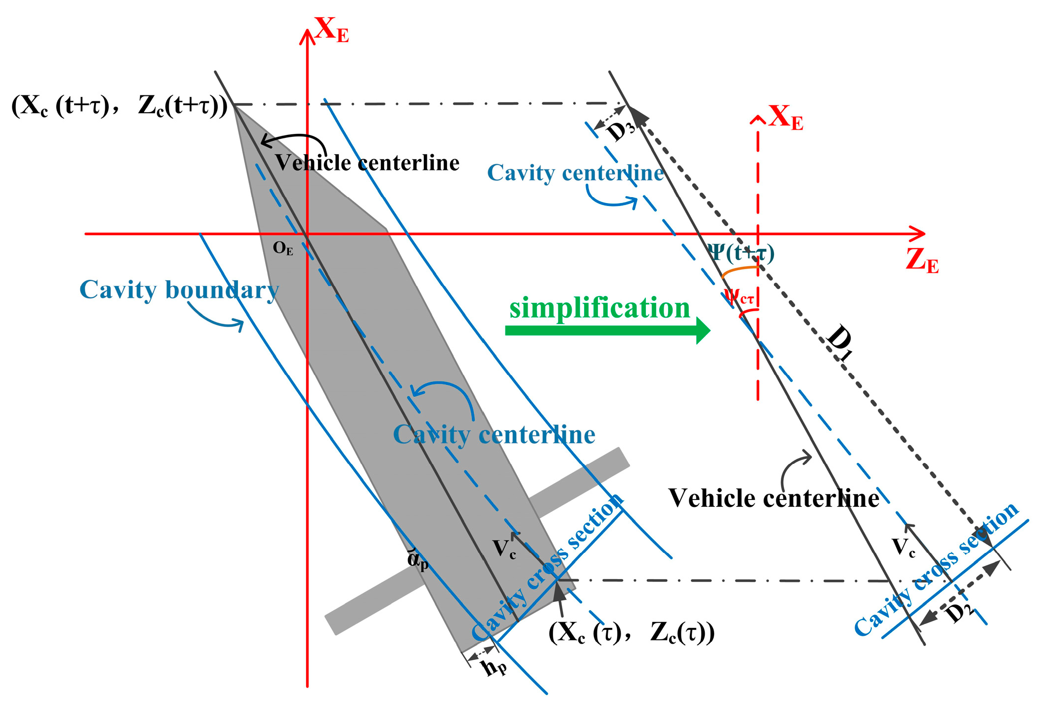
The planing force is induced by the interaction between the vehicle rear and cavity surface. Because of the cavity memory effect, the portion of the cavity that interacts with the vehicle is generated by the previous position and orientation of the cavitator. Therefore, there is a time delay τ = L b V . Additionally, the cavity section expands along the radial direction perpendicular to the cavitation velocity at the previous time. Figure 2 depicts the relative position between the supercavity and the vehicle.
The immersion depth h p and the immersion angle α p at the aft of the vehicle can be described as follows:
h p = D 2 + D 3 R c p + R b + R ( t + τ , L b ) , turn   clockwise D 2 D 3 R c p + R b R ( t + τ , L b ) ,   turn   anticlockwise , D 2 + D 3 + R ( t + τ , L b ) > R c p R b 0 , inside   the   cavity
α p = ψ ( t + τ ) ψ c τ + R ˙ c V ,   turn   clockwise   ψ ( t + τ ) ψ c τ R ˙ c V , turn   anticlockwise 0 ,   inside   the   cavity  
where R ˙ c is the supercavity contraction rate [11].
According to the relative position, some location parameters, including the angle ψ c τ and the cavitator sideslip angle β c ( t ) shown in Figure 2 can be calculated as:
D 1 = ( x c E ( t + τ ) x c E ( t ) ) cos ψ c τ ( z c E ( t + τ ) z c E ( t ) ) sin ψ c τ D 2 = D 1 tan ( ψ ( t + τ ) ψ c τ ) D 3 = ( z c E ( t + τ ) z c E ( t ) ) cos ψ c τ + ( x c E ( t + τ ) x c E ( t ) ) sin ψ c τ
ψ c τ = ψ t β c ( t ) β c ( t ) = atan ( w ( t ) x c q ( t ) u )
where t + τ expresses the current time, while t is the previous time when the cavitator passes the current position of the vehicle rear.
The previous position vector of the cavitator with respect to O E X E Y E Z E can be described as:
( x c E ( t ) , y c E ( t ) , z c E ( t ) ) = R b E r c + ( x b E ( t ) , y b E ( t ) , z b E ( t ) )
Rotation tensor R b E rotates the body-fixed reference frame to the earth-fixed reference frame.
According to previous research [37,38], the planing force F p and the corresponding moment M p can be represented as follows:
F p = ρ π V 2 R b 2 sin ( α p ( t , τ ) ) cos ( α p ( t , τ ) ) 1 R c p R b h p ( t , τ ) + R c p R b 2 R b + h p ( t , τ ) R b + 2 h p ( t , τ )
M p = r p × F p
where r p = 11 28 L b 0 0 .

2.5.2. Fin Forces

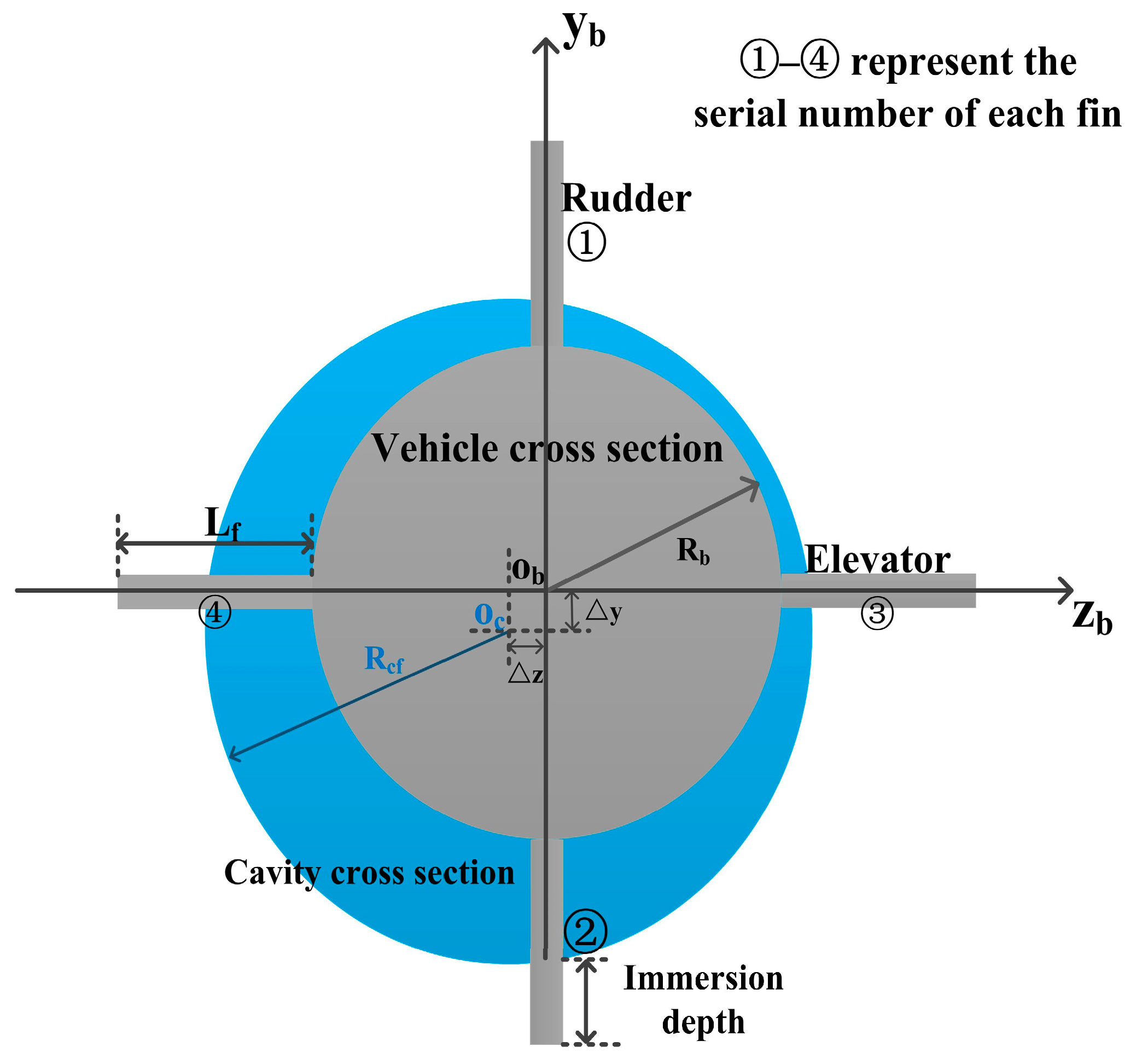
In this paper, the elevators provide lift to maintain longitudinal stability, while the rudders control the yaw channel. The hydrodynamic forces acting on the fins are closely related to the immersion depth shown in Figure 3, which can be described as the rudder efficiency n r i ( i = 1 , 2 ) and elevator efficiency n e i ( i = 3 , 4 ) , given as follows:
n r 1 = R b + L f + Δ y R c f 2 Δ z 2 L f n r 2 = R b + L f Δ y R c f 2 Δ z 2 L f n e 3 = R b + L f + Δ z R c f 2 Δ y 2 L f n e 4 = R b + L f Δ z R c f 2 Δ y 2 L f
where R c f is the radius of the cavity section at the tail fin. Δ y and Δ z denote the centerline offsets between the vehicle and supercavity along Y b -axis and Z b -axis at the tail fin, respectively.
The rudder hydrodynamic forces F r (moment M r ) and the elevator hydrodynamic forces F e (moment M e ) can be modeled as follows:
F r x i = 1 2 ρ S f C x n r i s V f f ( V sin ( δ r i + β ) x f q cos δ r i ) sin δ r i , i = 1 , 2 F r z i = 1 2 ρ S f C x n r i s V f f ( V sin ( δ r i + β ) x f q cos δ r i ) cos δ r i , i = 1 , 2 F e x i = 1 2 ρ S f C x n e i s V f f ( V sin ( α + δ e i ) x f r cos δ e i ) sin δ e i , i = 3 , 4 F e y i = 1 2 ρ S f C x n e i s V f f ( V sin ( α + δ e i ) x f r cos δ e i ) cos δ e i , i = 3 , 4
M r i = l r i × F r i , i = 1 , 2 M e i = l e i × F e i , i = 3 , 4
V f f = R b r ( R v b V b v + ω b b × r f )
Since the equivalent action points of F r and F e vary with the immersion depth, the position vectors of force centroids on each fin in O b X b Y b Z b are listed as follows:
l r 1 = [ x f , R b + ( 1 n r 1 2 ) L f , 0 ] l r 2 = [ x f , R b ( 1 n r 2 2 ) L f , 0 ] l e 3 = [ x f , 0 , R b + ( 1 n e 3 2 ) L f ] l e 4 = [ x f , 0 , R b ( 1 n e 4 2 ) L f ]
where r r = [ x f , 0 , 0 ] , x f = L b 7 .

2.5.3. Frictional Drag

In order to obtain the thrust, the frictional drag F f needs to be considered. F f and the wet area S w be expressed as follows [39,40]:
F f = 1 2 ρ V 2 cos 2 α p S w C d
S w = 4 R c p R c p R b tan α p ( ( 1 + u c 2 ) arctan ( u c ) u c ) + R c p 3 2 ( R c p R b ) tan α p ( ( u s 2 0.5 ) arcsin ( u s ) + 0.5 u s 1 u s 2 )
where the drag coefficient C d = 0.075 ( lg Re 2 ) 2 [41]; Reynolds number Re = V l p v k ; and the length of the wetted region l p = h p tan α p . The kinematic viscosity coefficient of the fluid is v k = 10 6   m 2 / s [42]; u c = h p R c p R b ; u s = 1 2 R c p h p ( R c p R b ) .

2.5.4. Cavitator Force

The cavitator deflection angles δ θ with respect to X b -axis and δ ψ with respect to Y b -axis are the control inputs. δ θ is adopted to maintain longitudinal stability, while δ ψ controls the yaw channel as heading control inputs [29]. The cavitator force and moment can be presented as follows:
F c = 0.5 ρ S n C x V c c 2 cos β c n c b V c c = R b c V c b = R b c ( R v b [ V , 0 , 0 ] T + w b × r c ) n c b = R c b [ 1 , 0 , 0 ] T
M c b = r c × F c b
V c c = R b c ( R v b V b v + ω b b × r c )
where r c = [ x c , 0 , 0 ] , x c = 17 28 L b ; β c denotes the angle between the x-axis and the resultant velocity in O c X c Y c Z c ; n c b is the projection of the normal direction of the cavitator in O E X E Y E Z E .

3. Controller Design

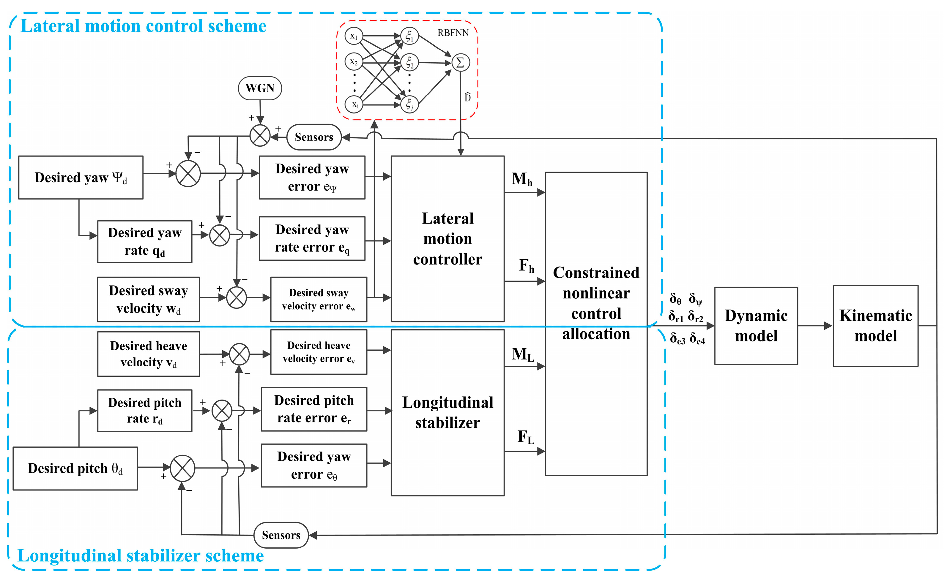
According to the above analysis, the motion control of a supercavitating vehicle is a multi-input and multi-output issue in the presence of highly coupled nonlinearity, external disturbances, and measurement errors from the sensors. In order to study the lateral maneuverability of a supercavitating vehicle, it is necessary to ensure its longitudinal stability. To solve the above problems, a parallel control structure is proposed, including a lateral motion controller and a longitudinal stabilizer, as shown in Figure 4. The dynamic controller adopts the sliding mode method to design desired control torques and control forces according to the desired linear and angular velocities. The adaptive RBFNN is introduced to estimate the external disturbances in the dynamic equations and compensate for the dynamic control law. The adaptive laws of the NN weights and control parameters are adjusted online in terms of state errors in real time. According to the actuator configuration of the supercavitating vehicle, the control input of each actuator is solved by nonlinear control allocation with constraints.

3.1. Lateral Motion Controller Design

The objective of the lateral motion controller is to regulate the actual yaw angle ψ following the desired yaw angle ψ d by designing the control law. For the derivation of the control law, the sliding mode surface is designed as follows:
S ψ = e ˙ ψ + C ψ e ψ , C 1 > 0
where e ψ = ψ ψ d denotes the yaw error.
Define the Lyapunov function candidate as follows.
V ψ 1 = 1 2 S ψ 2
By combining Equations (1), (2), (25) and (26), the derivative of Equation (26) can be obtained as follows:
V ˙ ψ 1 = S ψ S ˙ ψ = S ψ ( ( M h J y y + M p y J y y ) sec θ + q r sin θ cos 2 θ ψ ¨ d + C ψ e ˙ ψ )
where M h represents the total yaw moment provided by the cavitator and rudders.
The accessibility of the sliding mode condition guarantees that any original state in space can reach the sliding mode surface in finite time. The exponential reaching law is adopted as follows:
S ˙ ψ = k ψ S ψ ε ψ sgn ( S ψ )
where k ψ and ε ψ are the positive parameters that need to be determined.
Design the yaw control law as follows:
M h = J y y cos θ ( ψ ¨ d C ψ e ˙ ψ ε ψ sgn ( S ψ ) k ψ S ψ q r sin θ cos 2 θ ) M p y
To analyze the stability, substituting Equation (29) into Equation (27) yields:
V ˙ ψ 1 = ε ψ S ψ k ψ S ψ 2 0
According to the Lyapunov stability theory, the yaw control system can converge to a small neighborhood around zero in finite time.
As known from previous research [43], the threshold value of the sway velocity that causes the planing force is 1.64 m/s. In order to avoid the planing force and guarantee the stability of lateral motion for a supercavitating vehicle, the sway velocity is controlled to zero by designing a proper lateral force.
Define the Lyapunov function candidate as V w 1 = 1 2 e w 2 , and the sway velocity error is formulated as e w = w w d .
Differentiating V w 1 yields V ˙ w 1 = e w e ˙ w = e w ( w ˙ w ˙ d ) = e w ( u q m ˙ m w + F h m + F p m w ˙ d ) , where F h denotes the required resultant lateral force.
Based on the Lyapunov theory, the lateral control force can be determined by adopting the backstepping techniques:
F h = m w ˙ d + m ˙ w F p z m u q m k w e w m ε w sgn ( e w )
where k w and ε w denote the positive control gain.
Substituting the lateral control force into V ˙ w 1 , then V ˙ w 1 can be rewritten as:
V ˙ w 1 = k w e w 2 ε w e w
Since V ˙ w 1 is negative definite, the sway velocity controller is asymptotically stable.

3.2. Longitudinal Stabilizer Design

The objective of the longitudinal stabilizer is to maintain depth. Transform the depth control into regulating the heave velocity and pitch angle both to zero. The design of the longitudinal stabilizer is similar to the lateral motion controller design.
The pitch angle tracking error can be expressed as e θ = θ θ d .
The sliding mode surface for the pitch angle control is chosen as follows:
S θ = e ˙ θ + C θ e θ
Design the Lyapunov function candidate as follows:
V θ = 1 2 S θ 2
Based on Equations (1), (2) and (34), the derivative of Equation (34) is
V ˙ θ = S θ ( M L J z z + M p z J z z θ ¨ d + C θ e ˙ θ )
where M L is the total pitch moment provided by the cavitator and elevators.
The same exponential reaching law is selected as described in Section 3.1. Then, the pitch control moment can be given as follows
M L = J z z ( k θ S θ ε θ sgn ( S θ ) C θ e ˙ θ + θ ¨ d ) M p z
With respect to longitudinal velocity control, the longitudinal velocity should be kept at zero in order to make the supercavitating vehicle sail at a fixed depth.
Substituting Equation (36) into V ˙ θ , then V ˙ θ can be rewritten as
V ˙ θ = k θ S θ 2 ε θ S θ
Consider the Lyapunov function candidate as follows:
V v = 1 2 e v 2
where e v denotes the longitudinal velocity tracking error.
By differentiating Equation (38) and utilizing Equation (1), the derivative V ˙ v can be obtained as follows:
V ˙ v = e v ( G y m + F L m + F p y m u r m ˙ m v + v ˙ d )
where F L demonstrates the resultant force that is required to maintain the longitudinal velocity zero.
According to the Lyapunov theory, design the dynamic control law as
F L = m k v e v G y F p y + m u r + m ˙ v m v ˙ d
where k v is a positive parameter.
Substituting Equation (40) into Equation (39) yields
V ˙ v = k v e v 2
Therefore, it is obvious that longitudinal stability can be guaranteed by the proposed control laws based on the Lyapunov theory.

3.3. Adaptive RBFNN Approximator Design

The dynamics of a supercavitating vehicle are subjected to ocean-induced disturbances and model uncertainties, which seriously affect control accuracy. In order to solve these problems, RBFNN is utilized to predict the uncertainties in the supercavitating vehicle model online and compensates for the dynamic control laws. RBFNN is a three-layer feedforward network, including an input layer, a hidden layer, and an output layer. Some studies have proved that it has good estimation ability for continuous nonlinear functions [15,44]. This paper mainly studies the lateral motion, and the dynamic equations can be rewritten as follows:
w ˙ = u q m ˙ m w + 1 m ( G z + F c z + i = 1 2 F r z i + F p z ) + D w
q ˙ = 1 J y y ( M c y + i = 1 2 M r y i + i = 3 4 M e y i + M p y ) + D q
where D v and D q denote the uncertainties, including the model uncertainties and external disturbances.
The RBFNN estimation of nonlinear uncertainties can be expressed as follows:
D w , q = W w , q ξ ( x ) + χ w , q
where ξ j ( x ) adopts a Gaussian function, given by ξ j ( x ) = exp ( x ( t ) c j 2 2 b j 2 ) ; W v , q is the ideal NN weights; χ v , q denotes the estimation error of the RBFNN; the network input is x ( t ) = e ˙ w , q , e w , q T ; c j and b j represent the center vector and the base width value of the j t h hidden node, respectively.
In order to obtain a reasonable NN weight, the weight adaptive law can be given according to the Lyapunov function. The actual estimation of disturbances and the weight adaptive law can be expressed as follows:
D ^ w , q = W ^ w , q ξ ( x )
W ^ ˙ q = S ψ ξ ( x ) γ q cos θ W ^ ˙ w = e w ξ ( x ) γ w
where W ^ w , q  is the estimation of W * w , q ; γ q and γ w are positive constants.
Define the difference between the ideal weight and actual RBFNN weight as follows.
W ˜ w , q = W ^ w , q W w , q
The control gain ε ψ has a significant influence on the sliding mode dynamics. The larger ε ψ is, the faster the system can converge to the origin with undesired chattering [45]. Therefore, it is necessary to design a reasonable value of ε ψ to obtain a better control performance. Because χ w , q is bounded and can be small enough, the positive control gains ε ψ and ε w can satisfy the following conditions:
χ q ε ψ cos θ χ w ε w
With the sliding mode surface of the yaw tracking control and the sway velocity tracking error, the adaptive law of ε ψ and ε w can be designed as follows:
ε ^ ˙ ψ = 1 λ q S ψ ε ^ ˙ w = 1 λ w e w
ε ˜ ψ = ε ^ ψ ε ψ ε ˜ w = ε ^ w ε w
where λ q and λ w are the positive constants to be determined; ε ψ and ε w are the ideal control gains.
According to the above analysis, the lateral dynamic control laws can be redesigned as follows:
M h = J y y cos θ ( ψ ¨ d C ψ e ˙ ψ ε ^ ψ sgn ( S ψ ) k ψ S ψ q r sin θ cos 2 θ ) M p y J y y D ^ q
F h = m w ˙ d + τ ^ w F p z m u q m k w e w m ε ^ w sgn ( e w ) m D ^ w
where τ ^ is the estimation of m ˙ ; define the difference between the estimated and actual values of m ˙ as τ ˜ = τ ^ m ˙ .
Let the adaptive law of τ ^ be
τ ^ ˙ = w e w ρ m ( t )
Select the Lyapunov function candidate as follows:
V ψ 2 = 1 2 S ψ 2 + 1 2 γ q W ˜ q 2 + 1 2 λ q ε ˜ ψ 2
V w 2 = 1 2 e w 2 + 1 2 γ w W ˜ w 2 + 1 2 λ w ε ˜ w 2 + 1 2 ρ τ ˜ 2
By combining Equations (28), (48), (52)–(55), Equation (54) and Equation (55) can be further derived as follows:
V ˙ ψ 2 = S ψ S ˙ ψ + γ q W ˜ q W ˜ ˙ q + λ q ε ˜ q ε ˜ ˙ q = - S ψ W ˜ q ξ ( x ) sec θ + S ψ χ q sec θ k ψ S ψ 2 ε ^ ψ S ψ + γ q W ˜ q W ^ ˙ q + λ q ε ˜ ψ ε ^ ˙ ψ = S ψ χ q sec θ k ψ S ψ 2 ε ^ ψ S ψ ε ˜ ψ S ψ k ψ S ψ 2 ( χ q sec θ ε ^ ψ ε ˜ ψ ) S ψ 0
V ˙ w 2 = e w e ˙ w + γ w W ˜ w W ˜ ˙ w + λ w ε ˜ w ε ˜ ˙ w + ρ τ ˜ τ ˜ ˙ = - k w e w e ε ^ w | e w | e w W ˜ w ξ ( x ) + e w x w + τ ˜ m ( t ) w e w + γ w W ˜ w W ^ ˙ w + λ w ε ˜ w ε ^ ˙ w + ρ τ ˜ τ ^ ˙ = - k w e w e W ˜ w ( γ w W ^ ˙ w e w ξ ( x ) ) + τ ˜ ( w e w m ( t ) + ρ τ ^ ˙ ) + e w x w ε ^ w | e w | + λ w ε ˜ w ε ^ ˙ w - k w e w e + ( | x w | ε ^ w ε ˜ w ) | e w | 0
Hence, the lateral motion control system is robust and globally asymptotically stable.

3.4. Control Allocation

The lateral dynamic control laws are obtained by the proposed lateral motion controller. As is seen from Equation (58), each dynamic control law is a multi-input and single-output issue. Therefore, the solution is not unique. Additionally, due to the rotational motion and the existence of the centerline offset between the vehicle and supercavity, the immersion depths of the elevators are different. To restrict the roll motion, Equation (59) is added as a constraint to maintain the rolling stability. The least squares method is used to solve the problem online in real time.
F h = f 1 ( δ ψ , δ θ , δ r 1 , δ r 2 ) M h = f 2 ( δ ψ , δ θ , δ r 1 , δ r 2 , δ e 3 , δ e 4 ) F L = f 3 ( δ ψ , δ θ , δ e 3 , δ e 4 ) M L = f 4 ( δ ψ , δ θ , δ r 1 , δ r 2 , δ e 3 , δ e 4 )
s . t .   i = 1 2 M r i + i = 3 4 M e i = 0

4. Numerical Simulation and Discussion

Numerical simulations are carried out to study the lateral maneuverability of the supercavitating vehicle by adopting the proposed lateral motion control scheme, and the results are presented in this section. Firstly, the maximum yaw rate is obtained, and the basic function of the sliding mode control method is verified. Subsequently, the supercavitating vehicle is controlled to a circular trajectory at maximum maneuverability with external disturbances in dynamic models. In contrast to the sliding mode controller without disturbance estimation, the maximum maneuverability and effectiveness of the adaptive RBFNN approximator are further verified. Finally, lateral maneuverability following a segmented trajectory following is conducted with sensor measurement noise to verify the robustness of the proposed control scheme.

4.1. Research on Maneuverability without External Disturbances

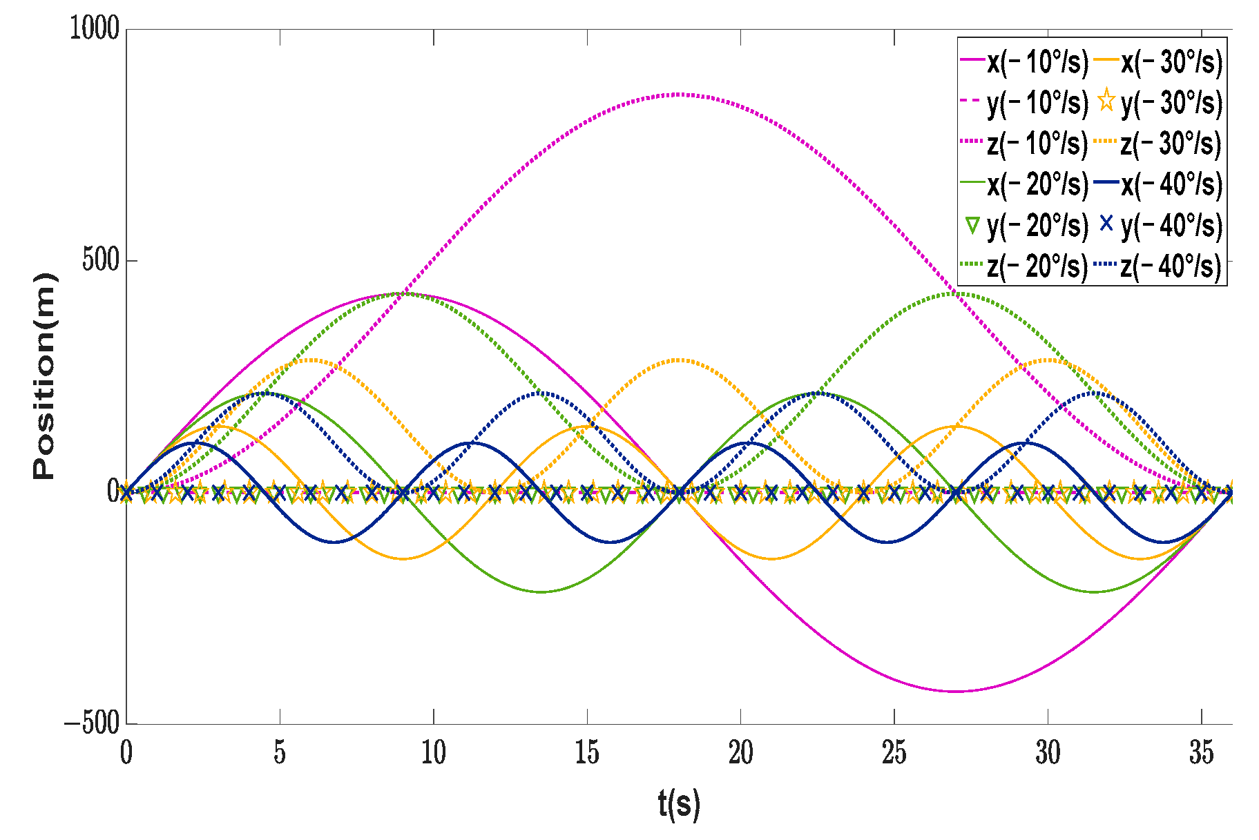
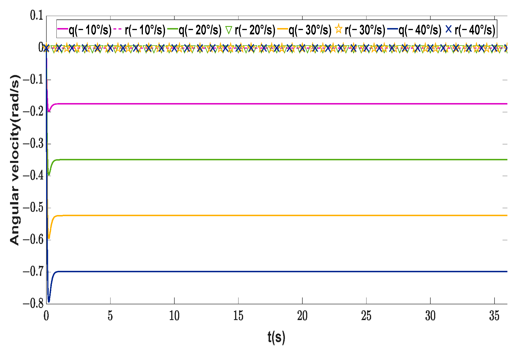
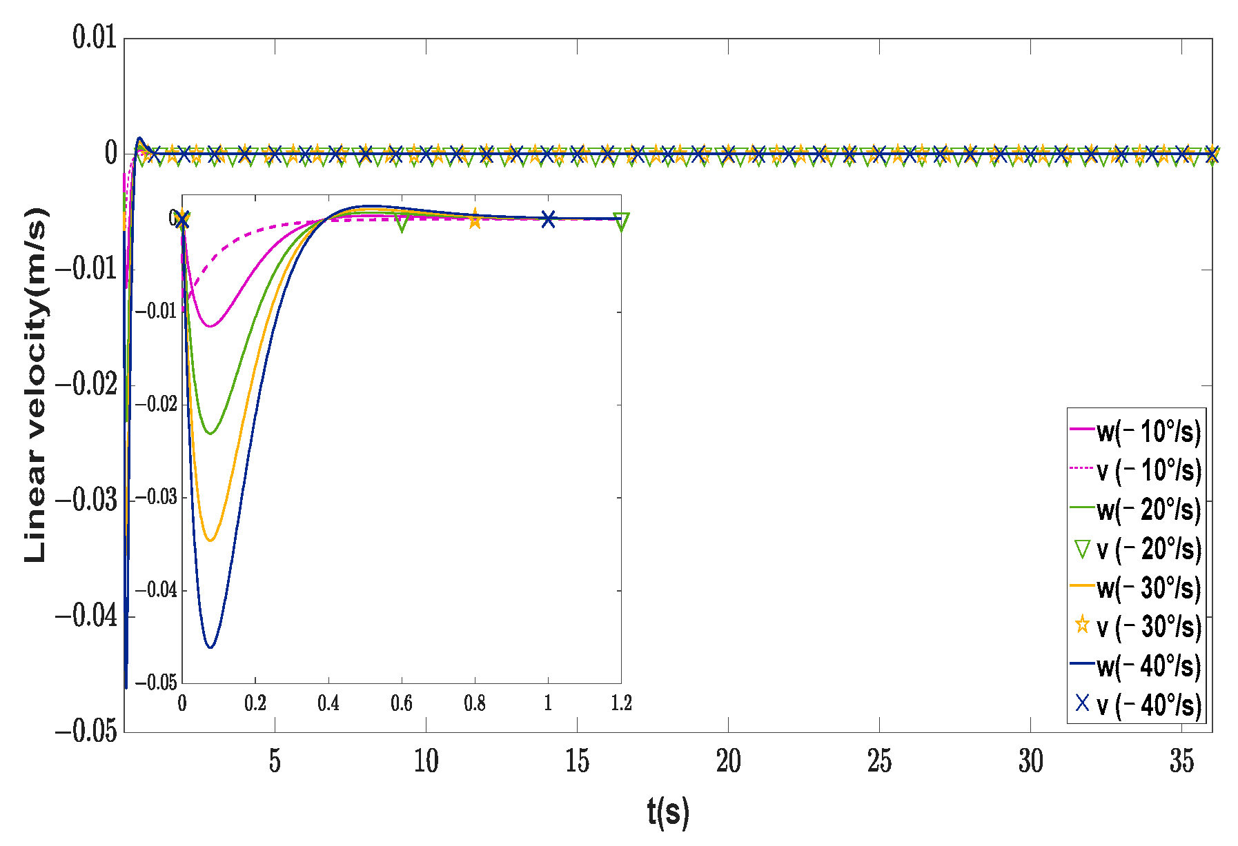
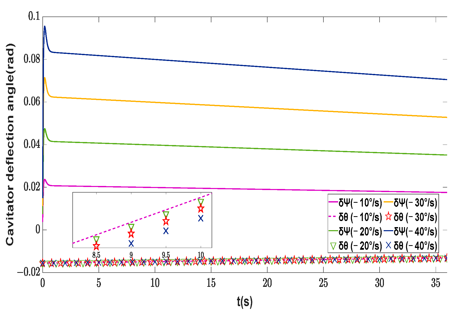
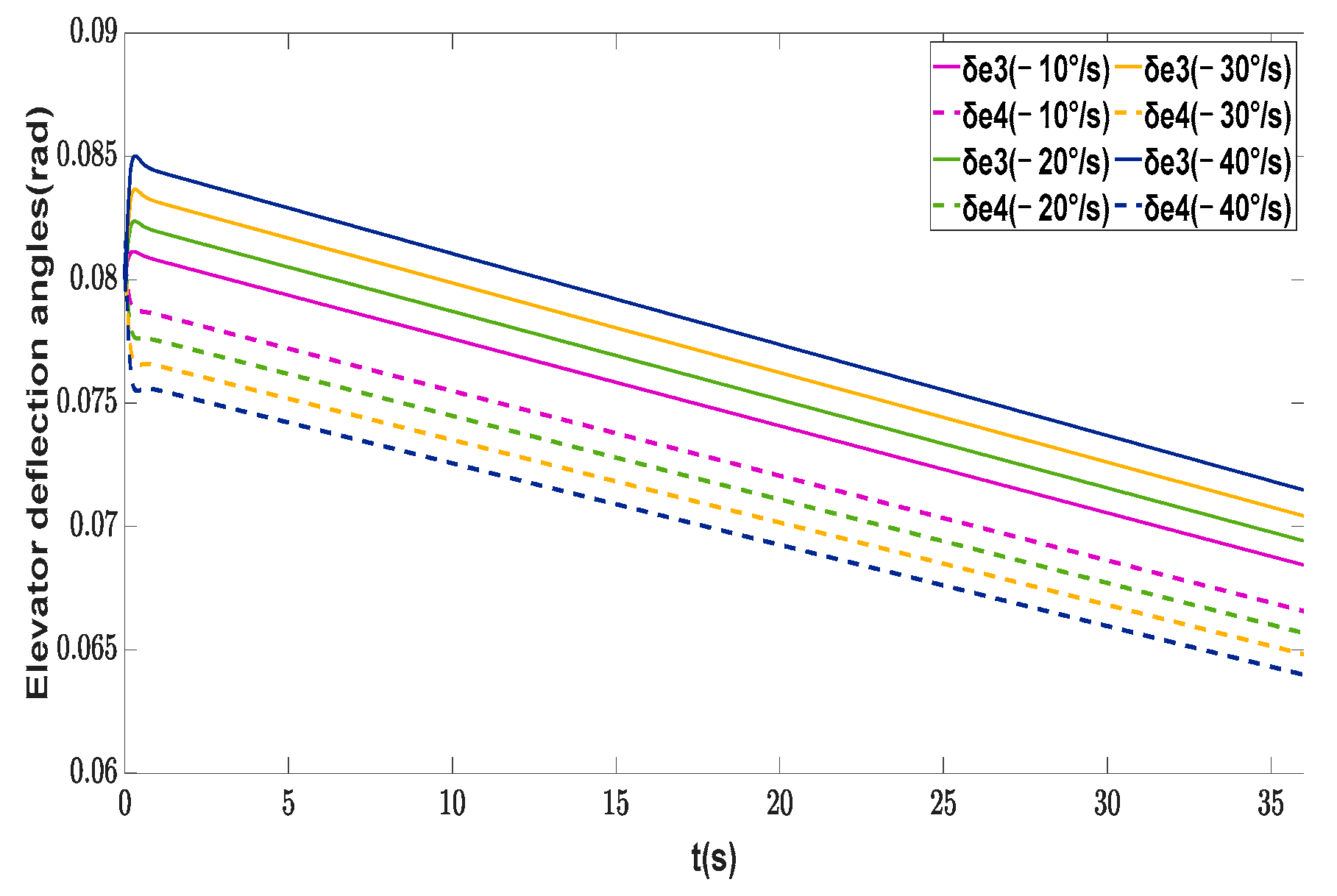
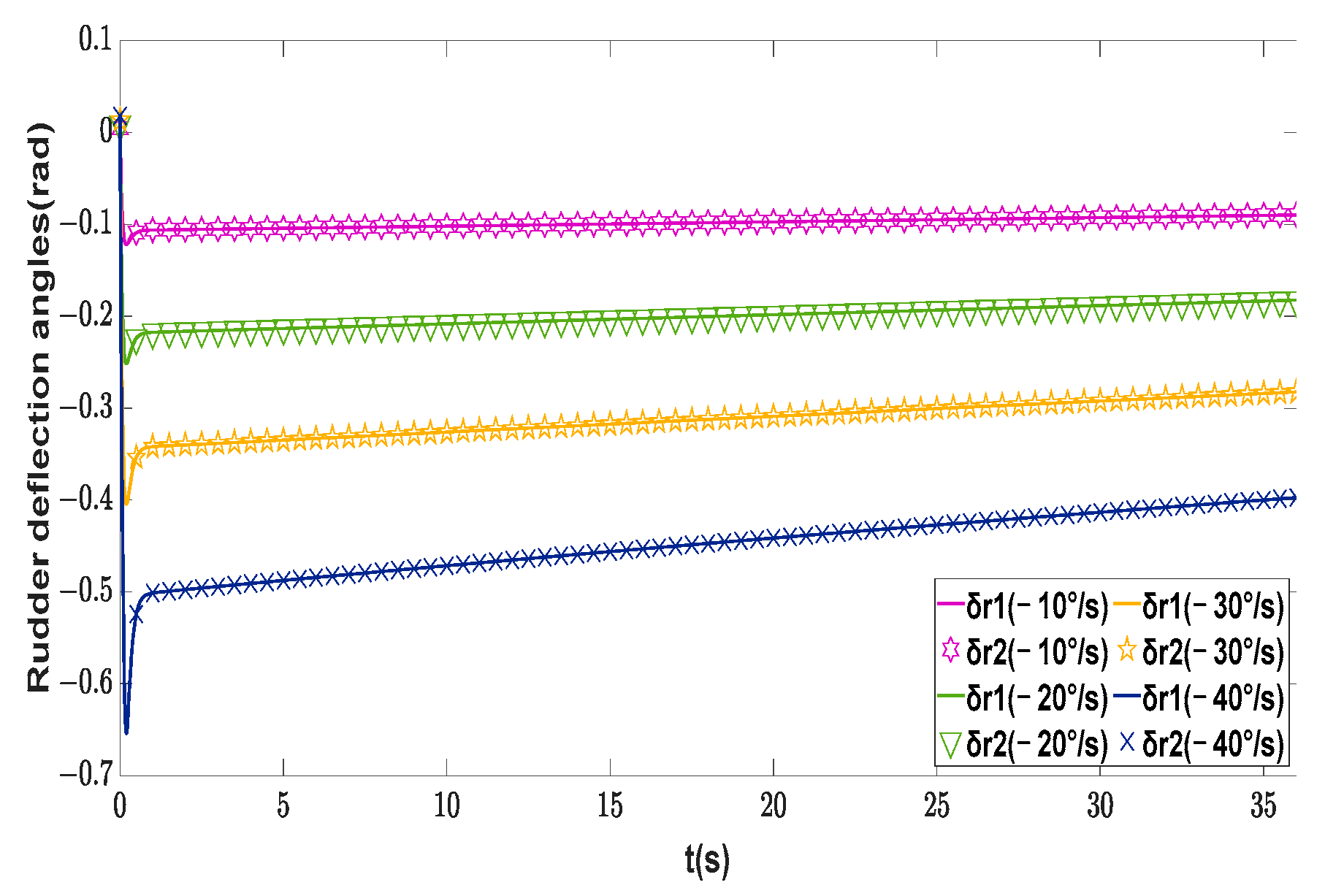
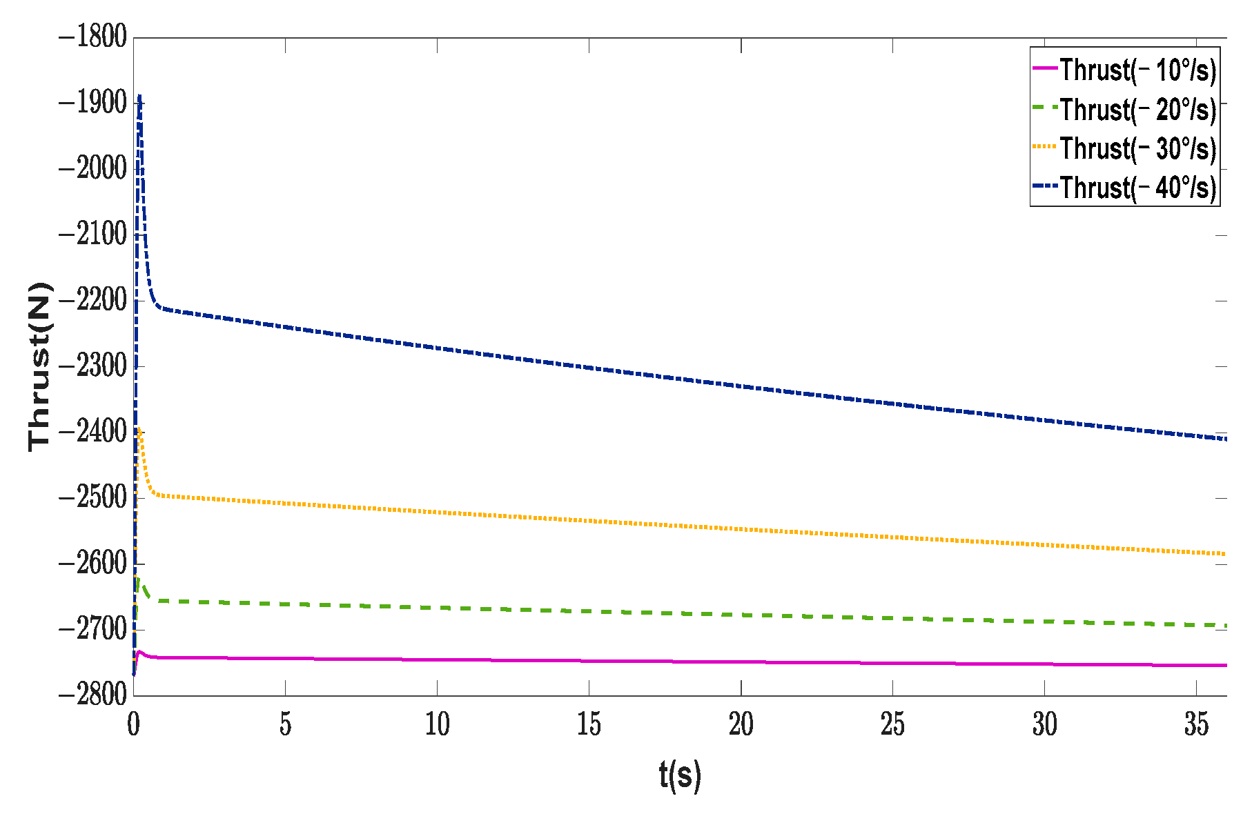
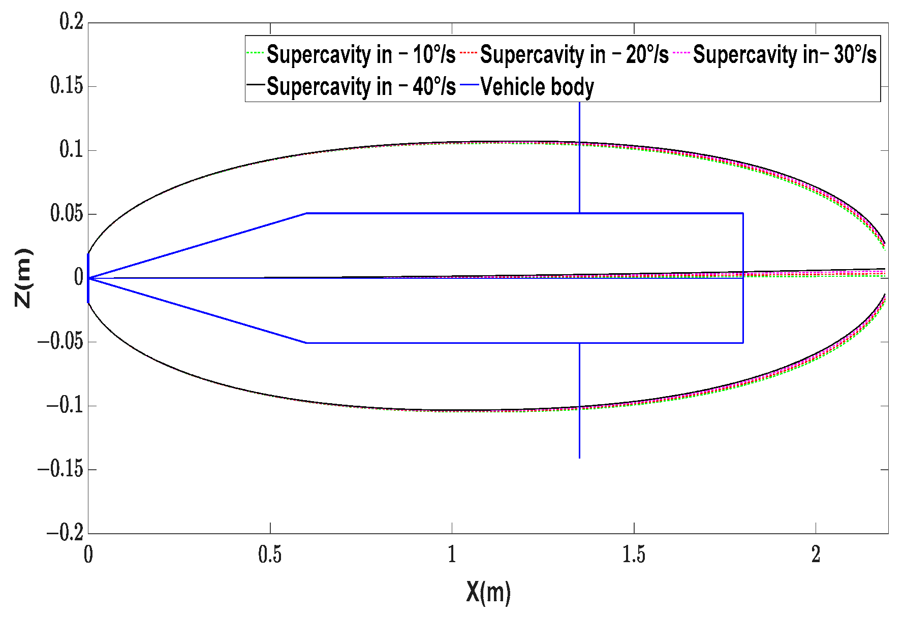
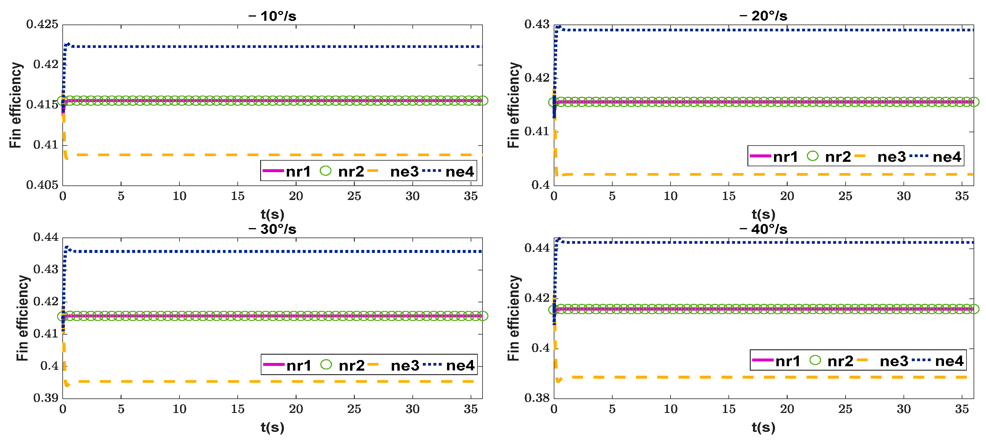
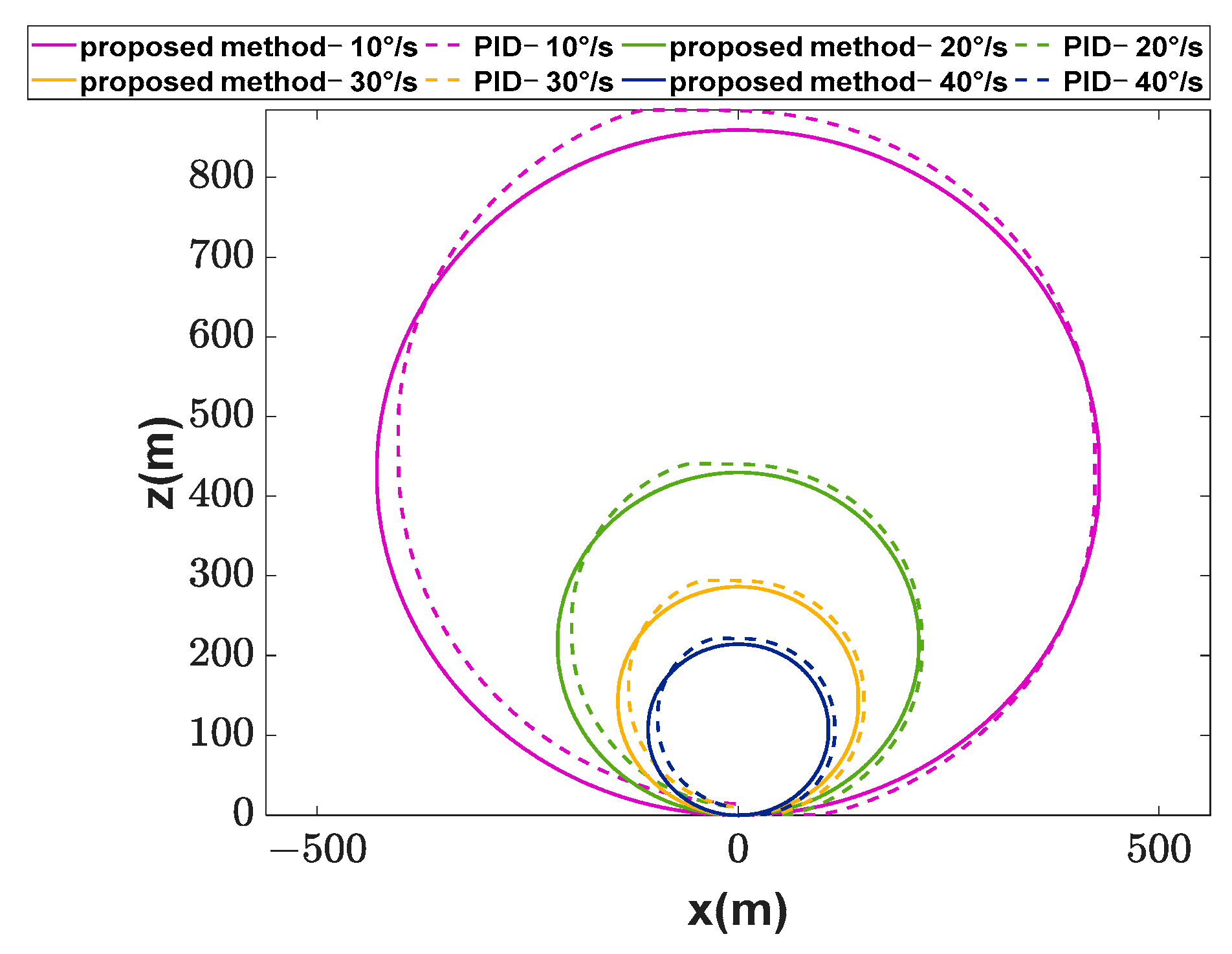
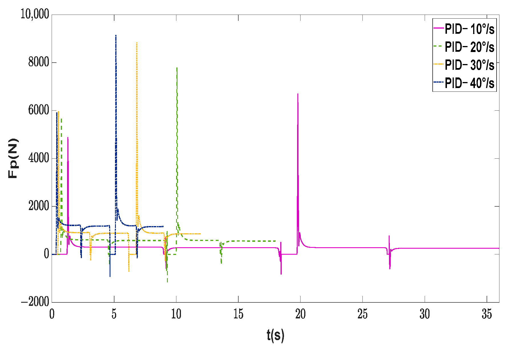
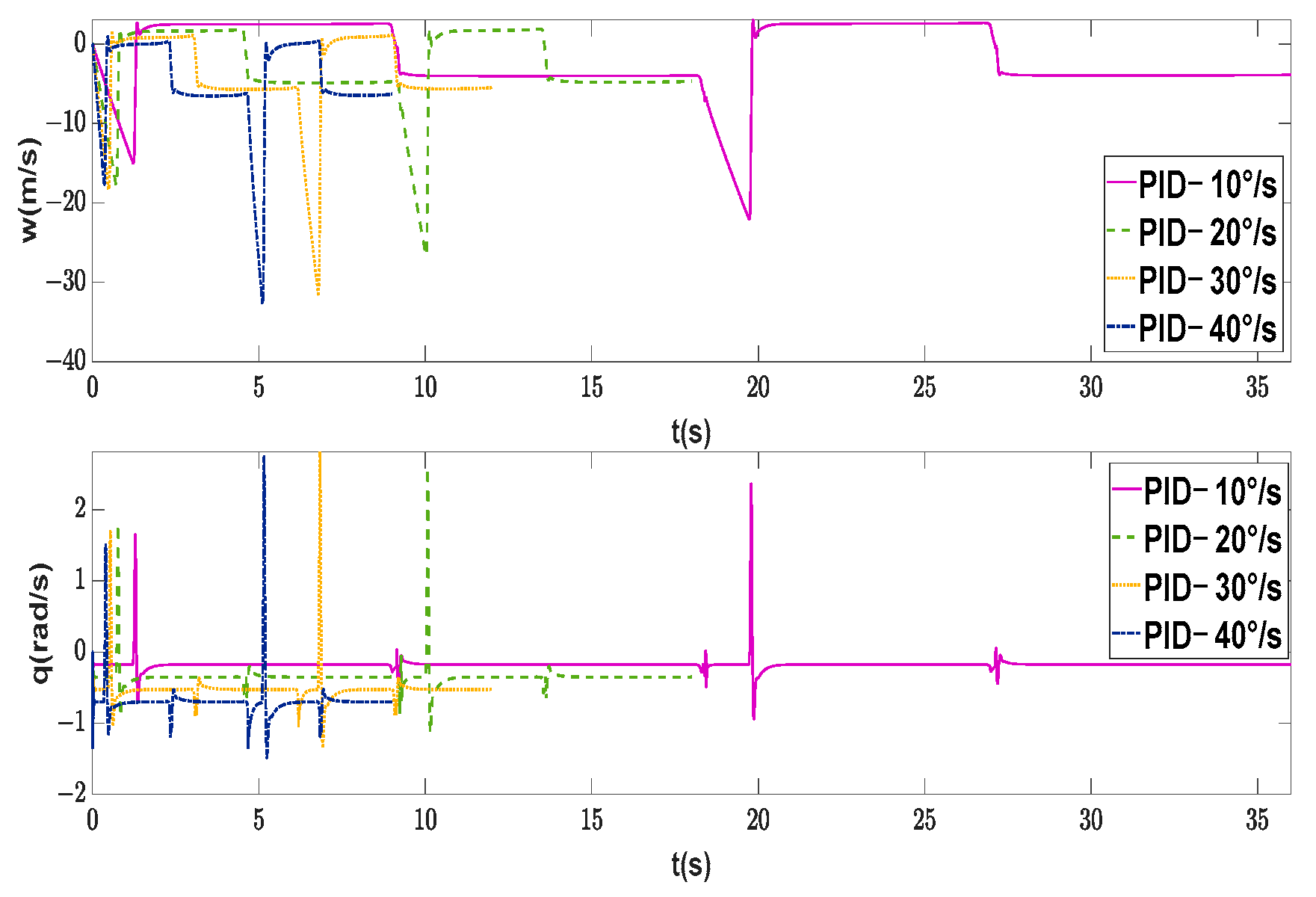
In order to verify the basic function of the proposed control method and obtain the maximum maneuverability of the supercavitating vehicle under different conditions without external disturbances, the motion control of the supercavitating vehicle is carried out at different yaw rates. The initial condition is selected as x e 0 , y e 0 , z e 0 = [ 0 , 0 , 0 ] and [ φ 0 , ψ 0 , θ 0 ] = [ 0 , 0 , 0 ] . Under the premise of longitudinal stability, the supercavitating vehicle moves in a circle. The main parameters of the proposed controller are determined as C ψ = C θ = 10 , k ψ = k w = k θ = k v = 10 , ε ψ = ε w = ε θ = 0.01 . As shown in Figure 5, Figure 6 and Figure 7, the supercavitating vehicle can maintain stable navigation within a range of yaw rates less than 40°/s. The numerical simulations demonstrate that the control inputs of the actuators cannot be solved successfully when the yaw rate exceeds 42°/s. Moreover, the pitch angles all remain zero under all motion conditions. As illustrated in Figure 7 and Figure 8, the longitudinal velocities and pitch rates are zero, which indicates longitudinal stability. The yaw rates and sway velocities exhibit a small overshoot and reach the desired states in a short period at the beginning of navigation. Via the constrained nonlinear solver, the deflection angle of each actuator is obtained, as depicted in Figure 9, Figure 10 and Figure 11. Due to fuel consumption, each control effort decreases as the supercavitating vehicle sails as well as thrust, shown in Figure 12. In addition, when the vehicle is rotating, there is a deviation between the centerlines of the vehicle and the supercavity, as shown in Figure 13. As a result, the immersion depths of the elevators on both sides are inconsistent, which results in different deflection angles for the two elevators. On the contrary, the immersion depths and deflection angles of the rudders are the same. The trend of the deflection angles of the elevators and rudders is inconsistent with the fin efficiency in Figure 14. In order to demonstrate the effectiveness of the proposed control method, classic PID control is adopted to control turning manoeuvers at four heading rates, whose trajectories are shown in Figure 15. It can be seen that the proposed control method has better performance than PID control. The PID method cannot avoid planning force all the time, according to Figure 16, which results in fluctuations in linear and angular velocities shown in Figure 17.

4.2. Verification of Maximum Maneuverability with External Disturbances

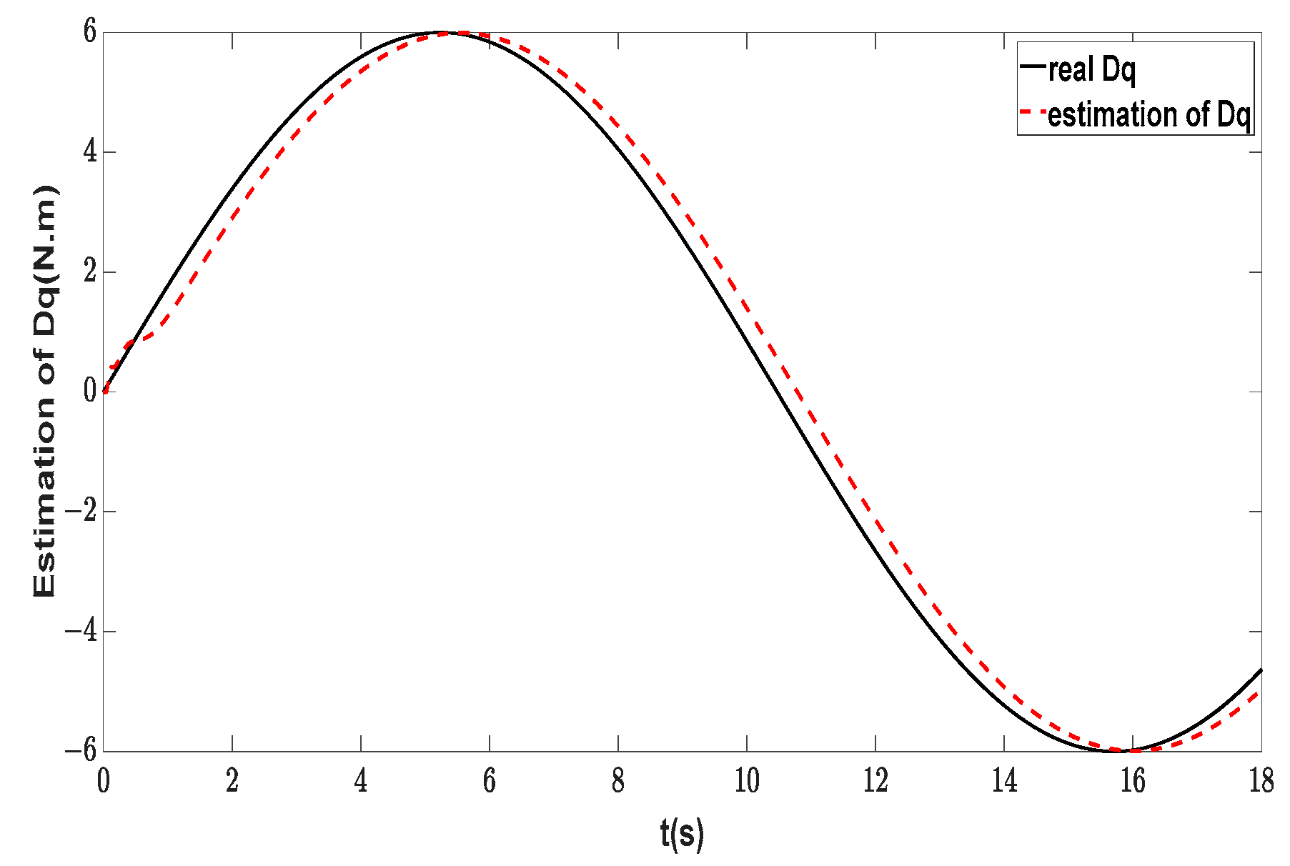
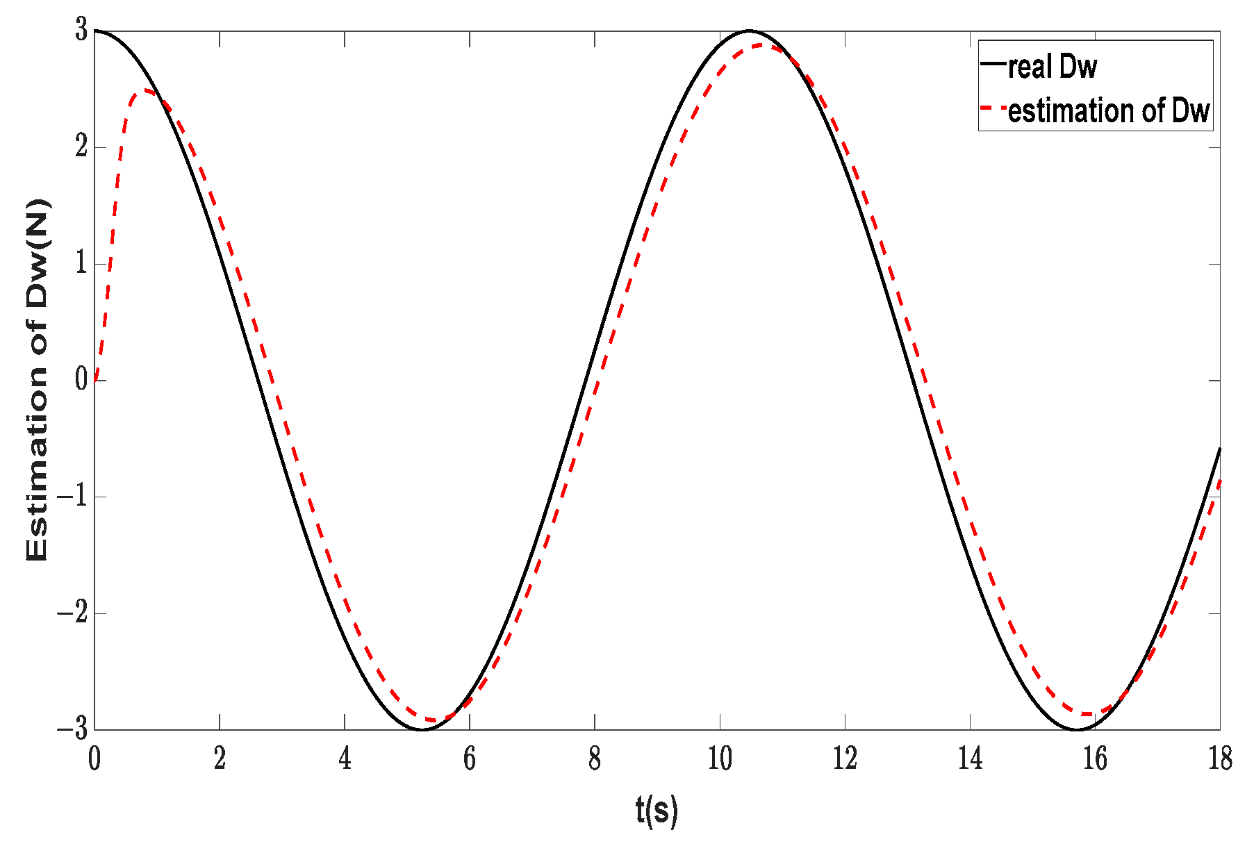
The proposed control strategy is applied to control the supercavitating vehicle at the maximum yaw rate in the presence of external disturbances. The adaptive RBFNN approximator for D q = 6 sin ( 0.3 t ) and D q = 6 sin ( 0.3 t ) adopts the structures of 1 × 7 × 1 and 2 × 7 × 1 by selecting [ e w ] and [ e q , e ˙ q ] as the respective input vectors. The parameters of the Gaussian function are chosen as b j = 0.1 and c j = [ 1 , 0.1 , 0.25 , 0 , 0.25 , 0.1 , 1 ] . The parameters in the NN weight adaptive laws and control laws are selected as γ w = γ q = 0.04 , λ q = λ w = 80 , and ρ = 0.008 . The initial condition is the same as described in Section 4.1. Other main relevant parameters of the proposed control scheme are designed as C ψ = C θ = 10 and k ψ = k w = k θ = k v = 10 . In order to attenuate chattering, the sign function in the dynamic control laws is replaced by the saturation function, expressed as s a t ( x ) = sgn ( x ) , a b s ( x ) > Δ x Δ , a b s ( x ) Δ , where Δ denotes the thickness of the boundary layer.
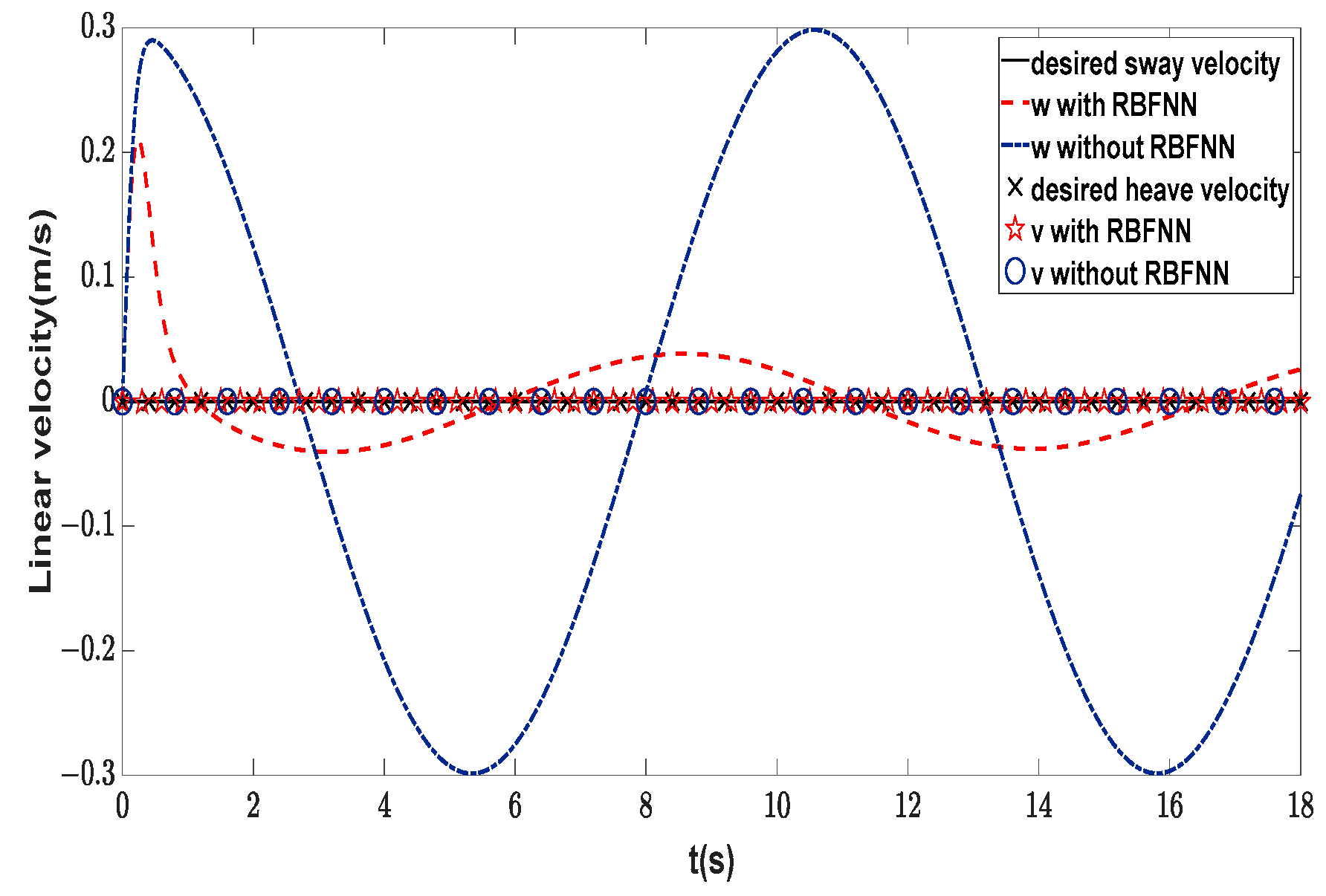
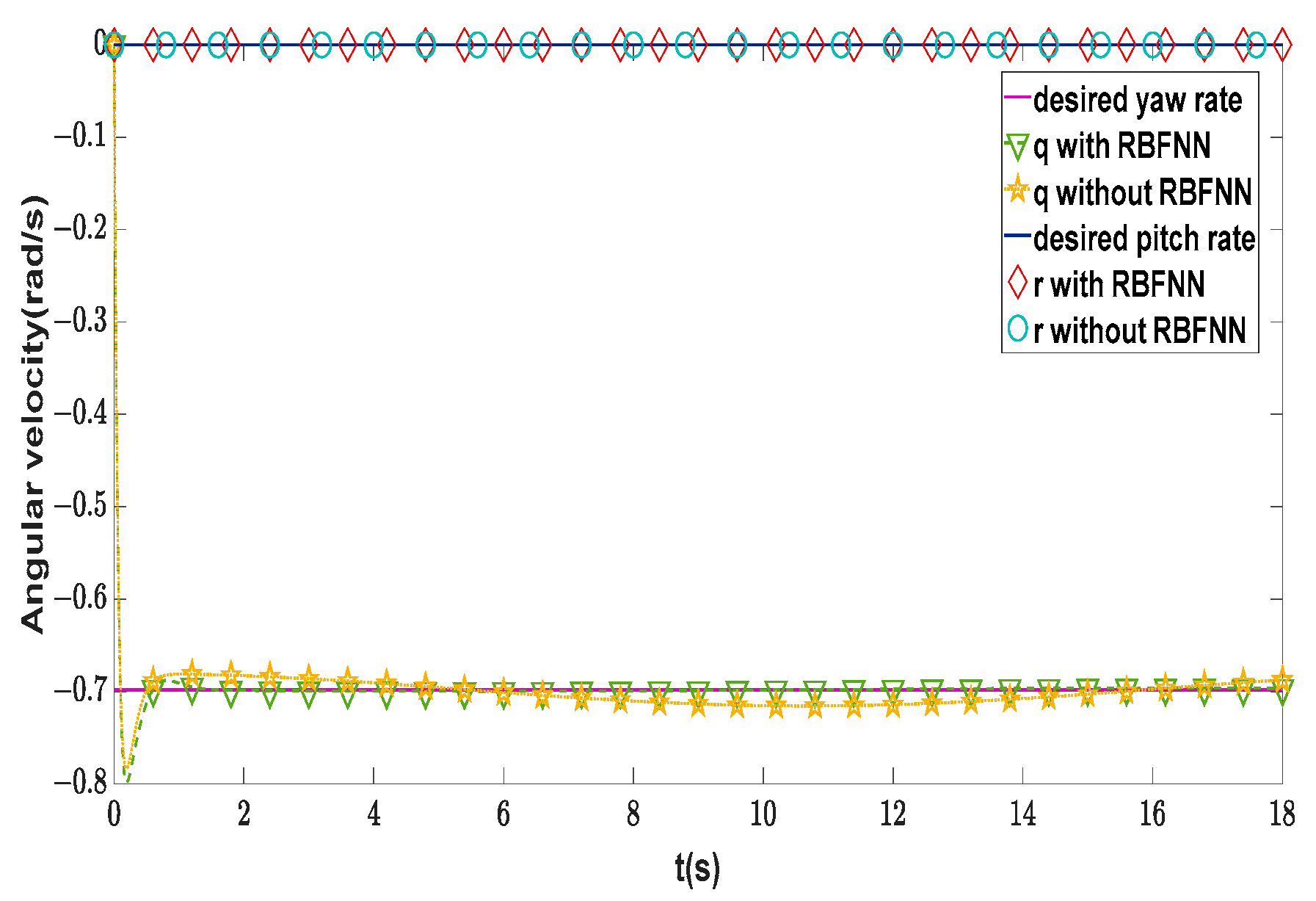
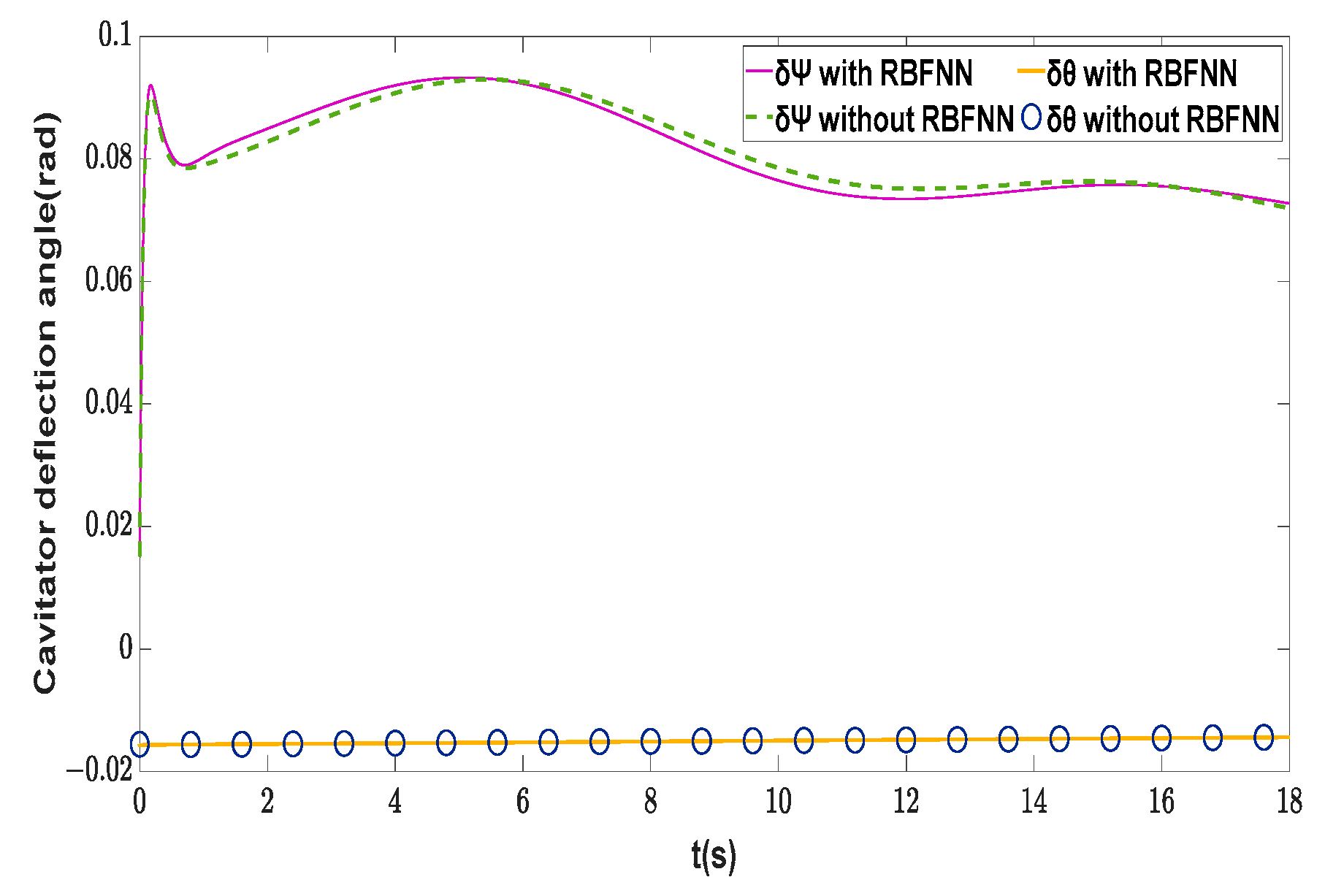
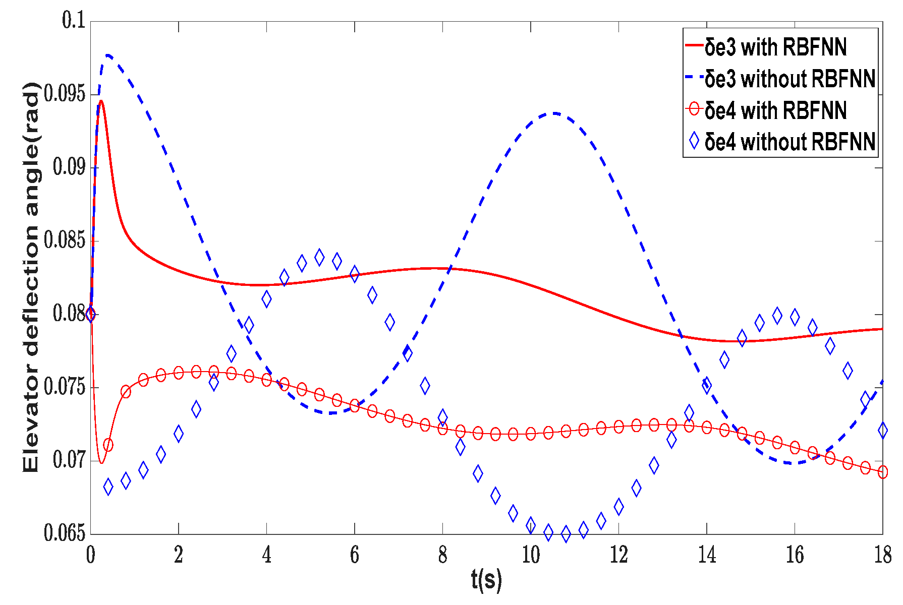
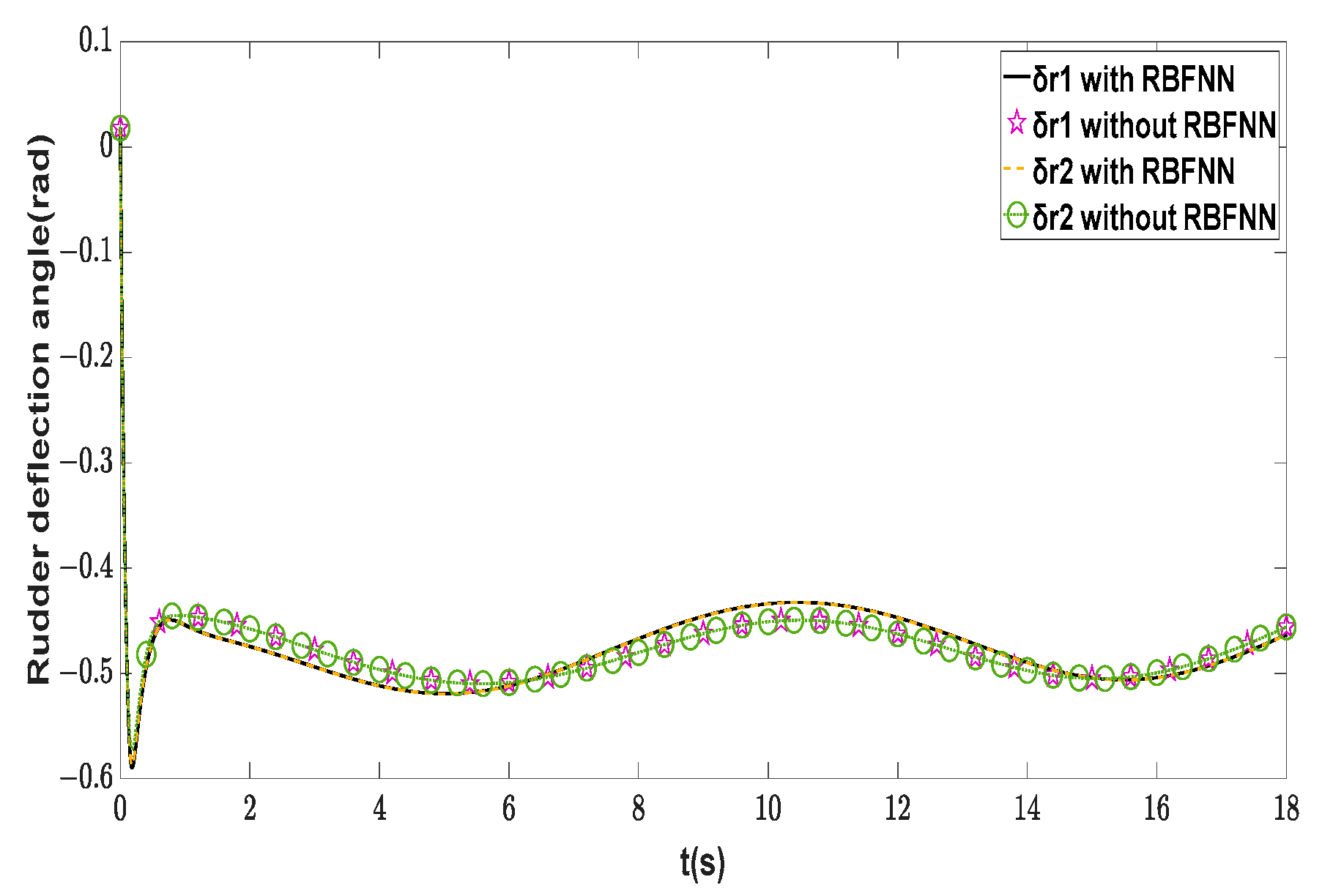
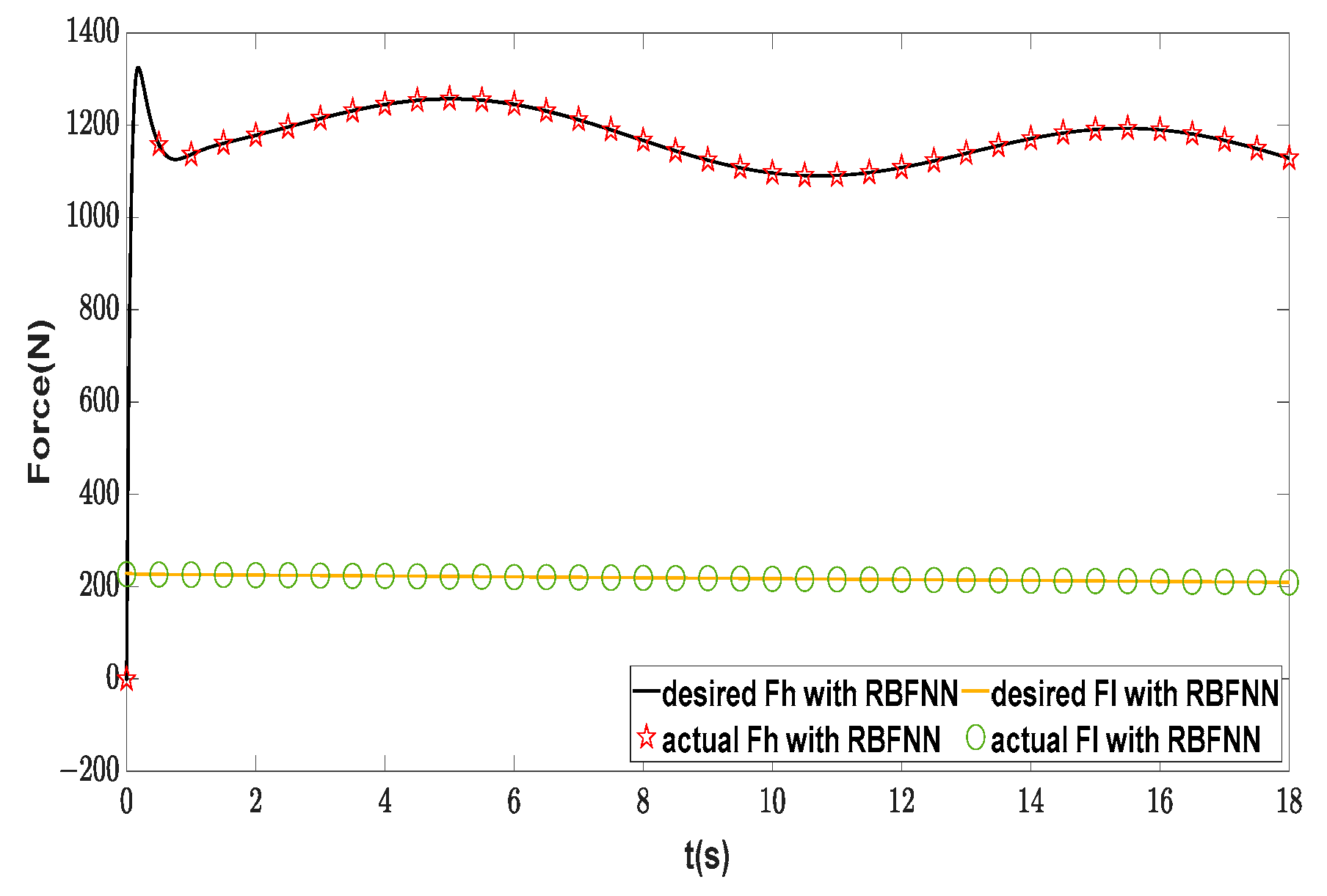
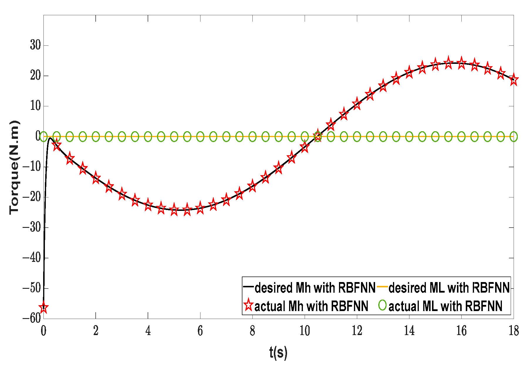
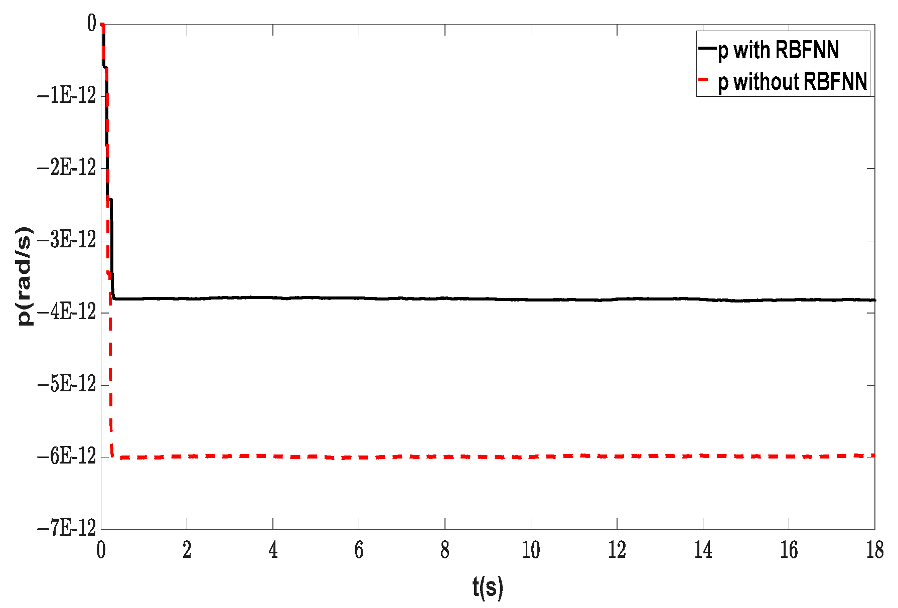
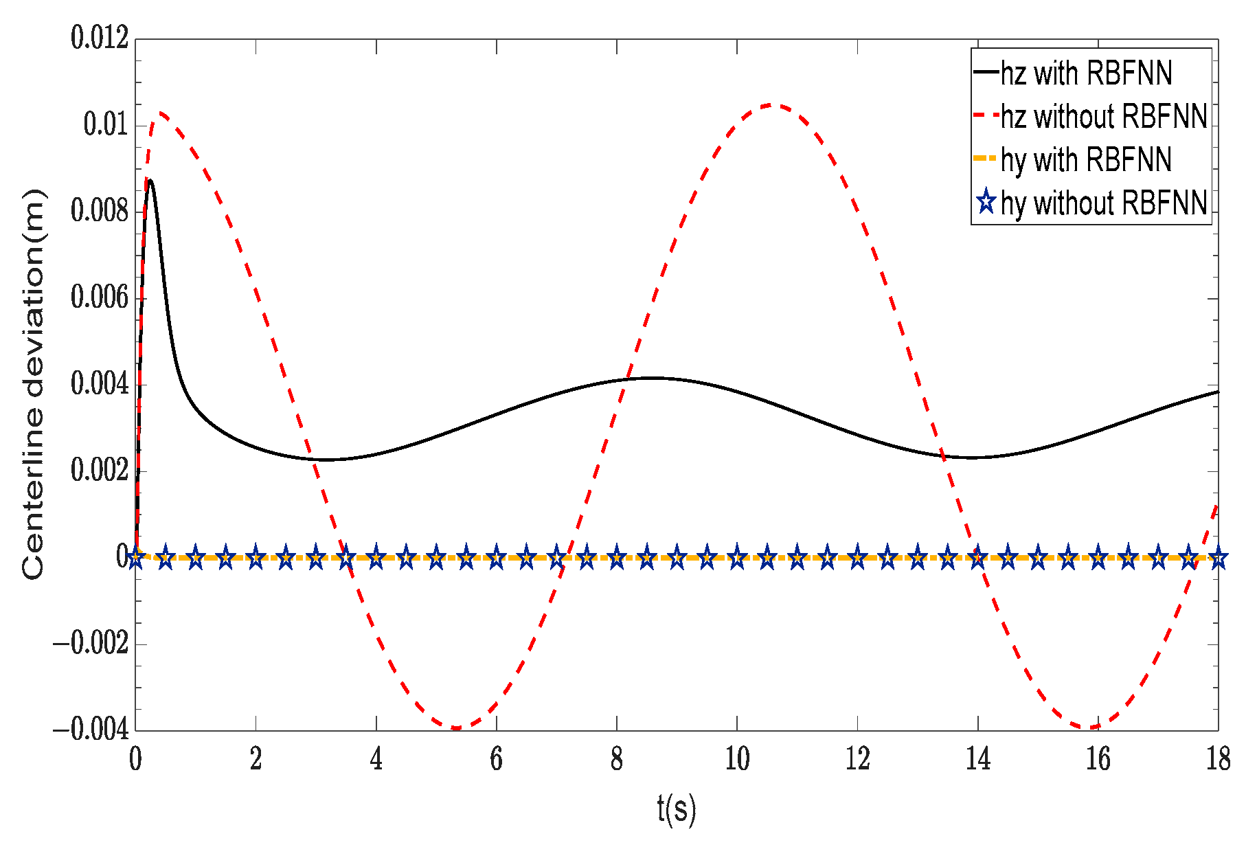
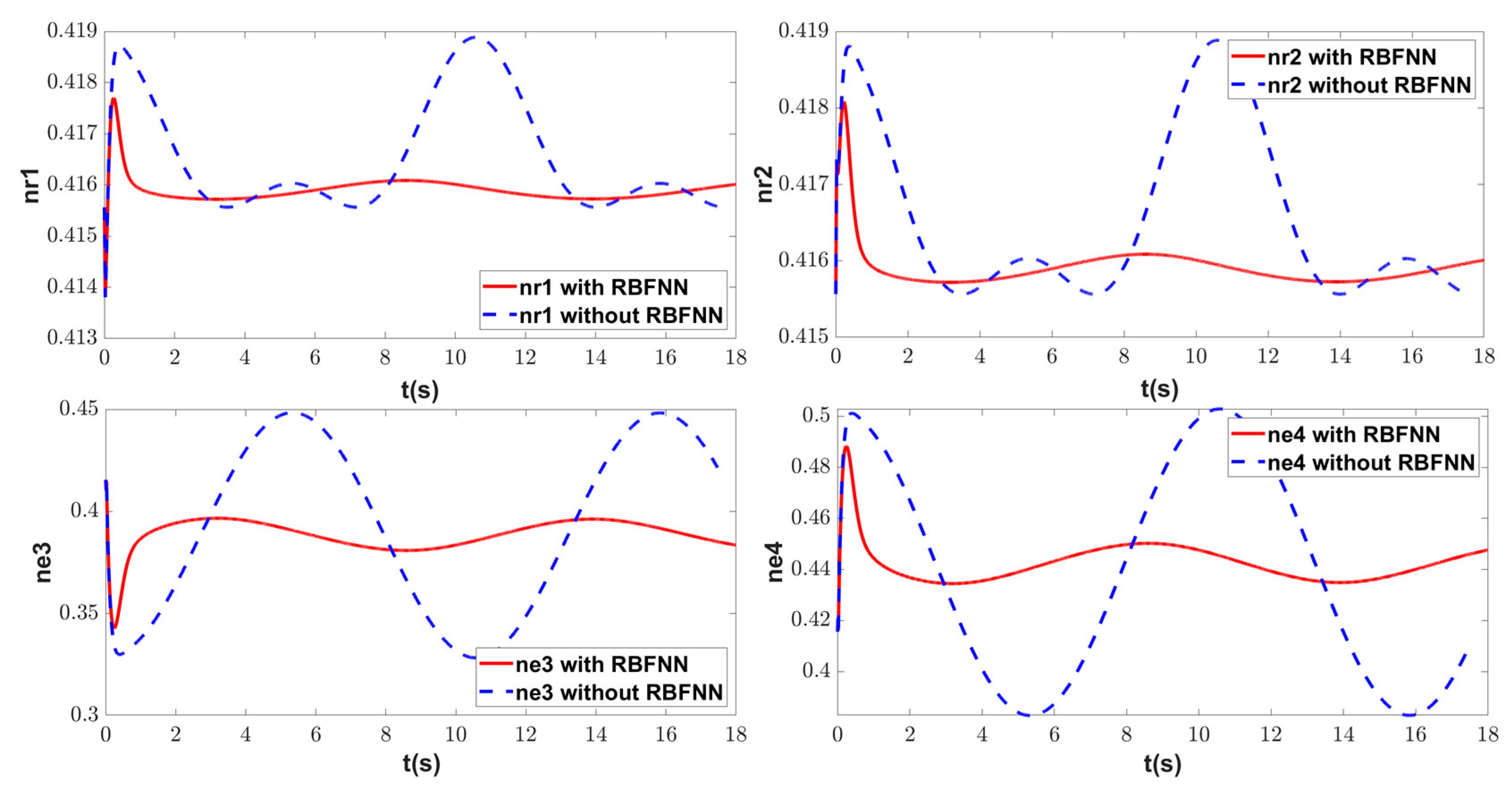
In order to verify the effectiveness of the proposed control scheme, the sliding mode controller without disturbance estimation is used as a comparison. As shown in Figure 18 and Figure 19, the proposed control scheme can smooth the linear and angular velocities and effectively reduce their errors. Figure 20 and Figure 21 show that the adaptive RBFNN can effectively estimate the external nonlinear disturbances and compensate for the dynamic control laws. The actuator control efforts can be solved by the proposed control allocation solver, as illustrated in Figure 22, Figure 23 and Figure 24. The proposed control scheme makes good improvements in terms of maximum deflection angles and change rate of deflection angles, especially the elevator deflection angles. The elevator deflection angles become gentler and their maximums are smaller after adopting the proposed control scheme. The control allocation accuracy is analyzed, and as shown in Figure 25 and Figure 26, there is no allocation error between the desired dynamic control laws and the actual dynamic control inputs. Additionally, rolling is effectively restricted, as shown in Figure 27, indicating the effectiveness of the control allocation solver. Figure 28 depicts the centerline offsets between the vehicle and the supercavity. It can be seen that centerline offsets in the longitudinal plane are basically zero regardless of whether adaptive RBFNN is adopted. On the contrary, the centerline deviation in the lateral plane leads to a significant difference in the fin efficiency of both elevators, as shown in Figure 29. As shown in Figure 30, the maximum deviation of the trajectory following is 1.4310 m, adopting the RBFNN adaptive sliding mode controller, while the maximum deviation of the trajectory following reaches 10.9948 m without RBFNN. Numerical simulation results demonstrate that the proposed control scheme can maintain the stability of the lateral motion and have strong robustness.

4.3. Piecewise Trajectory Following Control

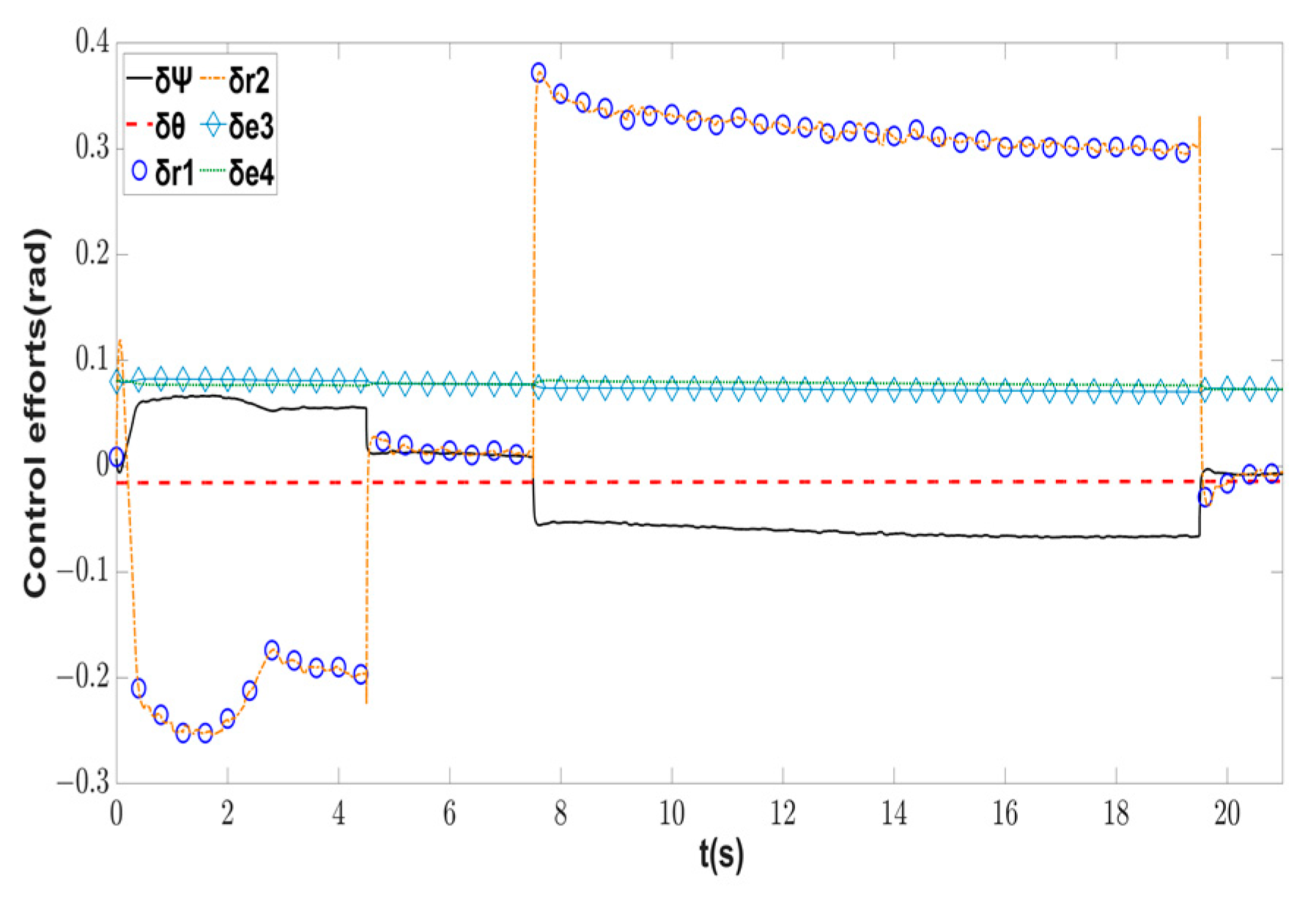
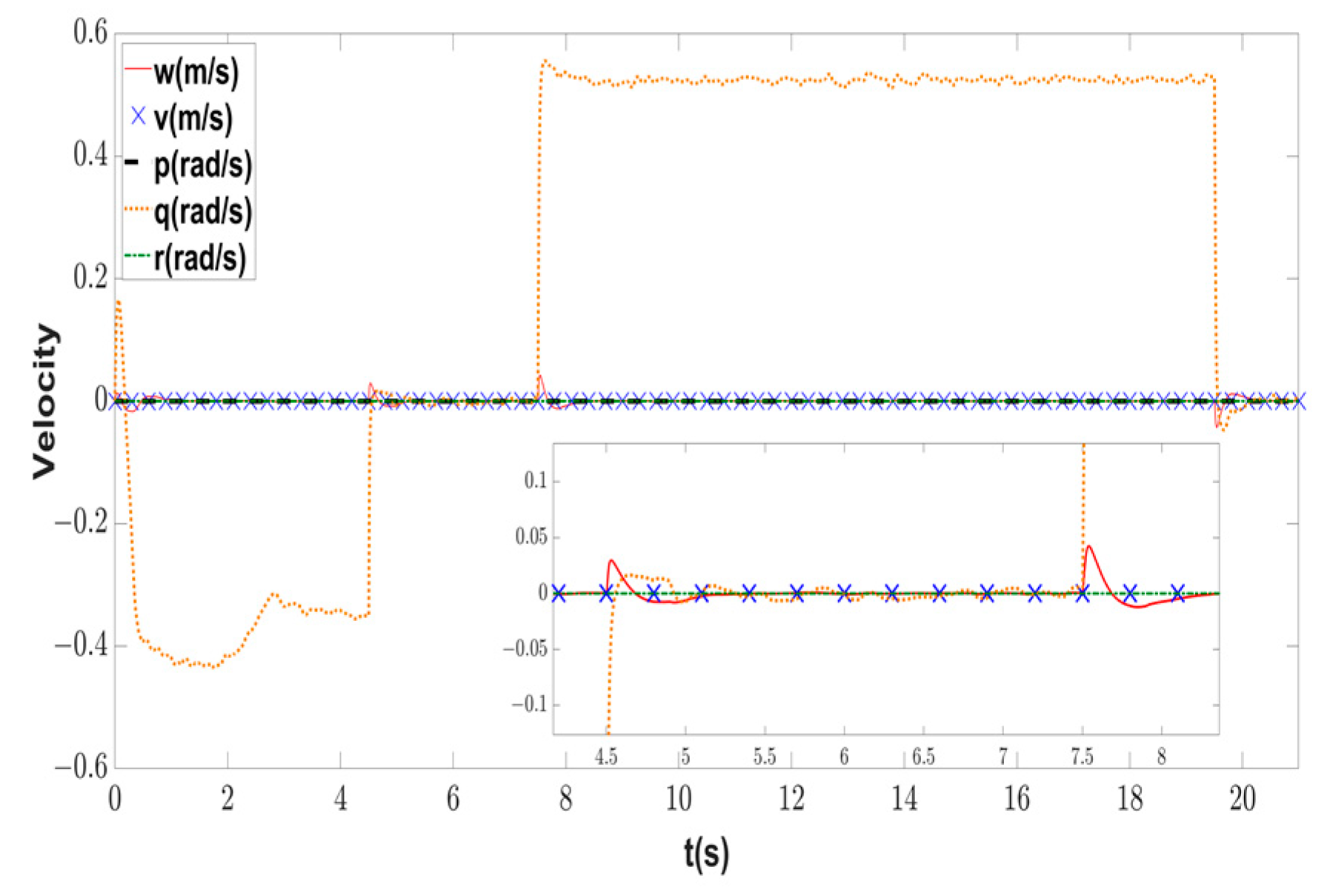
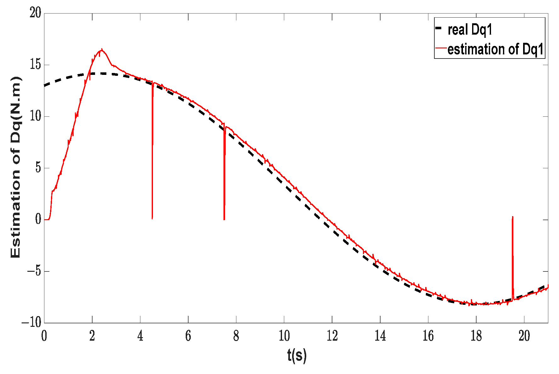
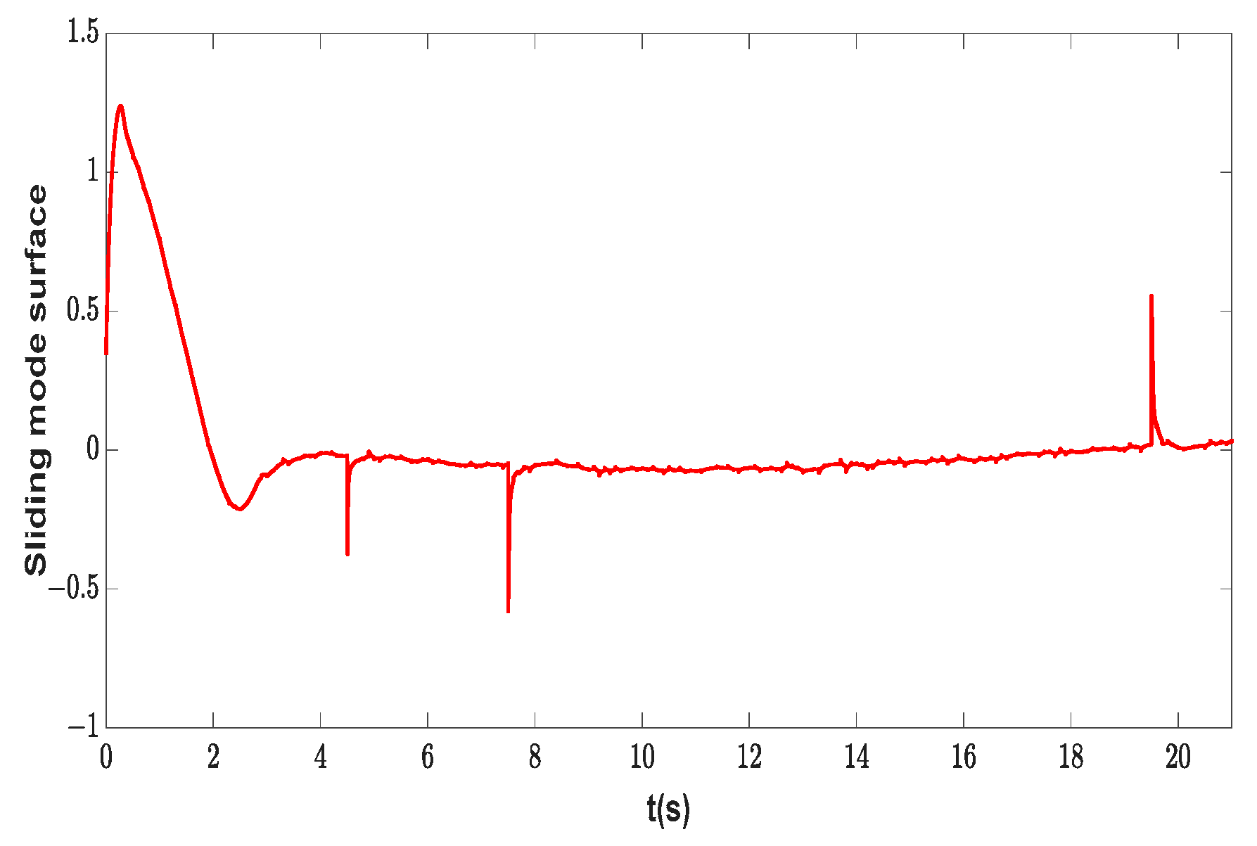
To further validate the robustness and effectiveness of the proposed control scheme, the piecewise trajectory following control is conducted, including rectilinear and curvilinear motion. We select D q 1 = 3 + 5 sin ( 0.2 t ) + 10 cos ( 0.2 t ) [46] as the external disturbance in the yaw dynamic model. In addition, measurement noise exists in reality in the sensor. To study the performance of the proposed control scheme in practice, white Gaussian noise (WGN) with a standard deviation of 0.25°/s is added into the yaw channel [47]. The initial condition and the main parameters of the RBFNN and control laws are the same as those described in Section 4.2. Fifty Monte Carlo simulations are conducted to carry out more investigation. It can be seen from Figure 31 that the supercavitating vehicle can follow the piecewise trajectory, whose distance measures 1575 m in 50 simulations. The mean maximum error is 2.1938 m, and RMSE is 1.0635 m. According to the errors, the 50 simulation results are close. Hence, only the first simulation result is analyzed below. WGN results in slight chattering in rudder deflection angles and rudder efficiency, as shown in Figure 32 and Figure 33. As shown in Figure 34, there is also slight chattering due to the existence of WGN. During the transition at different stages of the trajectory, the sway velocity appears in order to approach the desired path faster. Then the sway velocity is adjusted to zero quickly by the dynamic controller. The roll rate is always zero, which validates the effectiveness of the control allocation solver. Figure 35 demonstrates that the adaptive RBFNN approximator can effectively estimate a more complex external disturbance. There are several overshoots consistent with the sliding mode surface depicted in Figure 36, because the system states significantly change during the trajectory stage transition, resulting in large errors. At the same time, the inputs of the RBFNN are the state error and its derivative, and the weight control law is a function of the sliding mode surface. Hence, overshoots occur. The results show that the control scheme can achieve a satisfying performance in practical applications in the presence of actual measurement errors and external disturbances.

5. Conclusions

In this paper, highly coupled nonlinear 6-DOF kinematic and dynamic models with time-delay effects are constructed considering the unique hydrodynamic performance of a supercavitating vehicle. A lateral motion control strategy for a supercavitating vehicle based on longitudinal stability with planing force avoidance is proposed. The dynamic controller adopts the sliding mode method to improve the robustness of the system, and RBFNN is introduced to predict external disturbances and compensate for the dynamic control laws. The adaptive laws of NN weights and control parameters are designed to improve control performance. A control allocation solver with rolling restriction is utilized to solve the actuator control efforts by adopting the least squares method. Based on the proposed method, the lateral maneuverability of the supercavitating vehicle is studied. The results show that the maximum yaw rate should be in the range of less than 40°/s, which lays the foundation for further research on lateral maneuverability. Via numerical simulations of different trajectories of the supercavitating vehicle, the results are comprehensively analyzed from the aspects of fin efficiency, thrust, centerline offsets, etc. The results show that the proposed control strategy has strong robustness, high control accuracy, good control stability, and strong practical significance. Future work will include the experimental validation [48,49].

Author Contributions

Conceptualization and methodology, F.L. and G.Y.; software, G.Y.; formal analysis, G.Y. and J.X.; data curation, G.Y. and J.X.; writing—original draft preparation, G.Y.; writing—review and editing, G.Y. and J.X.; supervision, F.L.; funding acquisition, F.L. All authors have read and agreed to the published version of the manuscript.

Funding

This research was funded by the National Natural Science Foundation of China (NSFC) under Grant 11774432.

Data Availability Statement

The data that support the findings of this study are available from the corresponding authors upon reasonable request.

Acknowledgments

The authors gratefully acknowledge the helpful comments and suggestions of the reviewers.

Conflicts of Interest

The authors declare no conflict of interest.

References

  1. Xiang, X.; Yu, C.; Zhang, Q. Robust fuzzy 3D path following for autonomous underwater vehicle subject to uncertainties. Comput. Oper. Res. 2017, 84, 165–177. [Google Scholar] [CrossRef]
  2. Ruzzene, M.; Kamada, R.; Bottasso, C.; Scorcelletti, F. Trajectory Optimization Strategies for Supercavitating Underwater Vehicles. J. Vib. Control. 2008, 14, 611–644. [Google Scholar] [CrossRef]
  3. Fan, H.; Zhang, Y.; Wang, X. Longitudinal dynamics modeling and MPC strategy for high-speed supercavitating vehicles. In Proceedings of the 2011 International Conference on Electric Information and Control Engineering, Wuhan, China, 15–17 April 2011; pp. 5947–5950. [Google Scholar]
  4. Dzielski, J.; Kurdila, A. A benchmark control problem for supercavitating vehicles and an initial investigation of solutions. J. Vib. Control. 2003, 9, 791–804. [Google Scholar] [CrossRef]
  5. Lin, G.; Balachandran, B.; Abed, E.H. Dynamics and Control of Supercavitating Vehicles. J. Dyn. Syst. Meas. Control. 2008, 130, 021003. [Google Scholar] [CrossRef]
  6. Sanabria, D.E.; Balas, G.J.; Arndt, R.E. Planing avoidance control for supercavitating vehicles. In Proceedings of the 2014 American Control Conference, Portland, OR, USA, 4–6 June 2014; pp. 4979–4984. [Google Scholar] [CrossRef]
  7. Han, Y.; Xu, Z.; Guan, L. Predictive Control of a Supercavitating Vehicle Based on Time-Delay Characteristics. IEEE Access 2020, 9, 13499–13512. [Google Scholar] [CrossRef]
  8. Zhao, X.; Zhou, S.; Wang, X.; Jing, L. A Cascade Approach for Stability Control of Supercavitating Vehicle. In Proceedings of the Global Oceans 2020: Singapore—US Gulf Coast, Biloxi, MS, USA, 5–30 October 2020; pp. 1–6. [Google Scholar] [CrossRef]
  9. Kim, S.; Kim, N. Control method for ventilated supercavitating vehicle considering planing avoidance and stability. J. Eng. Marit. Environ. 2019, 233, 957–968. [Google Scholar] [CrossRef]
  10. Zou, W.; Wang, B. Longitudinal maneuvering motions of the supercavitating vehicle. Eur. J. Mech.-B/Fluids 2020, 81, 105–113. [Google Scholar] [CrossRef]
  11. Zhou, Y.; Sun, M.; Zhang, J.; Chen, Z. Depth and Attitude Coordinated Control for Supercavitating Vehicle Avoiding Planing Force. Machines 2022, 10, 433. [Google Scholar] [CrossRef]
  12. Zhao, X.; Zhang, X.; Ye, X.; Liu, Y. Sliding mode controller design for supercavitating vehicles. Ocean Eng. 2019, 184, 173–183. [Google Scholar] [CrossRef]
  13. Yang, G.; Lu, F.; Wu, L.; Xu, J. Design of Particle Swarm Optimization Adaptive Sliding Mode Controller Based on an Extended State Observer for the Longitudinal Motion of a Supercavitating Vehicle with Input Saturation. J. Sensors 2023, 2023, 2938089. [Google Scholar] [CrossRef]
  14. Wu, S.N.; Sun, X.Y.; Sun, Z.W.; Wu, X.D. Sliding-mode control for staring-mode spacecraft using a disturbance observer. Proc. Inst. Mech. Eng. Part G J. Aerosp. Eng. 2010, 224, 215–224. [Google Scholar] [CrossRef]
  15. Liu, E.; Yan, Y.; Yang, Y. Neural network approximation-based backstepping sliding mode control for spacecraft with input saturation and dynamics uncertainty. Acta Astronaut. 2022, 191, 1–10. [Google Scholar] [CrossRef]
  16. Fan, B.; Zhang, Y.; Chen, Y.; Meng, L. Intelligent vehicle lateral control based on radial basis function neural network sliding mode controller. CAAI Trans. Intell. Technol. 2022, 7, 455–468. [Google Scholar] [CrossRef]
  17. Esmaeili, N.; Kazemi, R.; Oreh, S.H.T. An adaptive sliding mode controller for the lateral control of articulated long vehicles. Proc. Inst. Mech. Eng. Part K J. Multi-Body Dyn. 2019, 233, 487–515. [Google Scholar] [CrossRef]
  18. Xia, Y.; Xu, K.; Li, Y.; Xu, G.; Xiang, X. Improved line-of-sight trajectory tracking control of under-actuated AUV subjects to ocean currents and input saturation. Ocean Eng. 2019, 174, 14–30. [Google Scholar] [CrossRef]
  19. Wang, W.; Xia, Y.; Chen, Y.; Xu, G.; Chen, Z.; Xu, K. Motion control methods for X-rudder underwater vehicles: Model based sliding Mode and non-model based iterative sliding mode. Ocean Eng. 2020, 216, 108054. [Google Scholar] [CrossRef]
  20. Xia, Y.; Xu, K.; Huang, Z.; Wang, W.; Xu, G.; Li, Y. Adaptive energy-efficient tracking control of a X rudder AUV with actuator dynamics and rolling restriction. Appl. Ocean Res. 2022, 118, 102994. [Google Scholar] [CrossRef]
  21. Miao, J.; Wang, S.; Tomovic, M.M.; Zhao, Z. Compound line-of-sight nonlinear path following control of underactuated marine vehicles exposed to wind, waves, and ocean currents. Nonlinear Dyn. 2017, 89, 2441–2459. [Google Scholar] [CrossRef]
  22. Jinghua, W.; Yang, L.; Guohua, C.; Yongyong, Z.; Jiafeng, Z. Design of RBF Adaptive Sliding Mode Controller for A Supercavitating Vehicle. IEEE Access 2021, 9, 39873–39883. [Google Scholar] [CrossRef]
  23. Ji, X.; He, X.; Lv, C.; Liu, Y.; Wu, J. Adaptive-neural-network-based robust lateral motion control for autonomous vehicle at driving limits. Control. Eng. Pract. 2018, 76, 41–53. [Google Scholar] [CrossRef]
  24. Wei, M.; Chen, G. Adaptive RBF neural network sliding mode control for ship course control system. In Proceedings of the 2011 Third International Conference on Intelligent Human-Machine Systems and Cybernetics, Hangzhou, China, 26–27 August 2011; pp. 27–30. [Google Scholar]
  25. Wang, X.; Deng, Z.; Peng, H.; Wang, L.; Wang, Y.; Tao, L.; Lu, C.; Peng, Z. Autonomous docking trajectory optimization for unmanned surface vehicle: A hierarchical method. Ocean Eng. 2023, 279, 114156. [Google Scholar] [CrossRef]
  26. Wang, X.; Li, B.; Su, X.; Peng, H.; Wang, L.; Lu, C.; Wang, C. Autonomous dispatch trajectory planning on flight deck: A search-resampling-optimization framework. Eng. Appl. Artif. Intell. 2023, 119, 105792. [Google Scholar] [CrossRef]
  27. Vanek, B.; Bokor, J.; Balas, G.J.; Arndt, R.E. Longitudinal Motion Control of a High-Speed Supercavitation Vehicle. J. Vib. Control 2007, 13, 159–184. [Google Scholar] [CrossRef]
  28. Bai, T.; Bi, X. Studies on lateral motion control of supercavitating vehicle. In Proceedings of the 2011 Third International Conference on Measuring Technology and Mechatronics Automation, Shanghai, China, 6–7 January 2011; pp. 377–380. [Google Scholar]
  29. Vanek, B.; Balas, G.J.; Arndt, R.E. Linear, parameter-varying control of a supercavitating vehicle. Control. Eng. Pract. 2010, 18, 1003–1012. [Google Scholar] [CrossRef]
  30. Xia, Y.; Xu, K.; Wang, W.; Xu, G.; Xiang, X.; Li, Y. Optimal robust trajectory tracking control of a X-rudder AUV with velocity sensor failures and uncertainties. Ocean Eng. 2020, 198, 106949. [Google Scholar] [CrossRef]
  31. Logvinovich, G.V. Hydrodynamics of Flows with Free Boundaries; Shanghai Jiao Tong University Press: Shanghai, China, 2012; pp. 97–126. ISBN 978-73-1308-814-7. [Google Scholar]
  32. Xinhua, Z.; Yao, S.; Zengkun, Q.; Minyan, H. Catastrophe characteristics and control of pitching supercavitating vehicles at fixed depths. Ocean Eng. 2016, 112, 185–194. [Google Scholar] [CrossRef]
  33. Han, Y.; Xu, Z.; Guo, H. Robust predictive control of a supercavitating vehicle based on time-delay characteristics and parameter uncertainty. Ocean Eng. 2021, 237, 109627. [Google Scholar] [CrossRef]
  34. Doan, P.T.; Bui, P.D.H.; Vu, M.T.; Thanh, H.L.N.N.; Hossain, S. Stability Analysis of a Fractional-Order High-Speed Supercavitating Vehicle Model with Delay. Machines 2021, 9, 129. [Google Scholar] [CrossRef]
  35. Zhang, Y.-W.; Yuan, X.-L.; Deng, F. Fluid Dynamics of Supercavitating Underwater Vehicles; National Defense Industry Press: Beijing, China, 2014; p. 167. [Google Scholar]
  36. Li, Y.; Zhang, Y. The influence of cavity shape on maneuverability rotational movement of supercavitating vehicle. J. Vib. Shock. 2014, 33, 165–170. [Google Scholar]
  37. Nguyen, V. Dynamics and Control of Non-Smooth Systems with Applications to Supercavitating Vehicles; University of Maryland: College Park, MD, USA, 2011. [Google Scholar]
  38. Zhang, K.; Li, P.; Wang, Z.; Yan, K.; Chen, W.; Xu, L.H. Experimental study of planning force on supercavitating vehicle tail. J. Ship Mech. 2020, 24, 8–17. [Google Scholar]
  39. Gao, H. Research on the Integration of Guidance and Control of Underwater High Speed Vehicle; Harbin Engineering University: Harbin, China, 2017. [Google Scholar]
  40. Kim, S.; Kim, N. Integrated dynamics modeling for supercavitating vehicle systems. Int. J. Nav. Archit. Ocean Eng. 2015, 7, 346–363. [Google Scholar] [CrossRef]
  41. Kim, S.; Kim, N. Neural network-based adaptive control for a supercavitating vehicle in transition phase. J. Mar. Sci. Technol. 2015, 20, 454–466. [Google Scholar] [CrossRef]
  42. Newman, J.N. Marine Hydrodynamics; The MIT Press: Cambridge, MA, USA, 2018. [Google Scholar]
  43. Pang, A. Supercaviting Vehicle Control; Harbin Institute of Technology: Harbin, China, 2017. [Google Scholar]
  44. El Hajjami, L.; Mellouli, E.M.; Berrada, M. Neural network based sliding mode lateral control for autonomous vehicle. In Proceedings of the 2020 1st International Conference on Innovative Research in Applied Science, Engineering and Technology (IRASET), Meknes, Morocco, 16–19 April 2020; pp. 1–6. [Google Scholar]
  45. Cui, R.; Zhang, X.; Cui, D. Adaptive sliding-mode attitude control for autonomous underwater vehicles with input nonlinearities. Ocean Eng. 2016, 123, 45–54. [Google Scholar] [CrossRef]
  46. Jia, L.Y.; Zhu, Z.Y. Improved fractional-order integral sliding mode control for AUV based on RBF neural network. In Proceedings of the 2019 Chinese Automation Congress (CAC), Hangzhou, China, 1–3 December 2018. [Google Scholar]
  47. Sarhadi, P.; Noei, A.R.; Khosravi, A. Adaptive integral feedback controller for pitch and yaw channels of an AUV with actuator saturations. ISA Trans. 2016, 65, 284–295. [Google Scholar] [CrossRef]
  48. Walker, K.L.; Gabl, R.; Aracri, S.; Cao, Y.; Stokes, A.A.; Kiprakis, A.; Giorgio-Serchi, F. Experimental Validation of Wave Induced Disturbances for Predictive Station Keeping of a Remotely Operated Vehicle. IEEE Robot. Autom. Lett. 2021, 6, 5421–5428. [Google Scholar] [CrossRef]
  49. Gabl, R.; Davey, T.; Cao, Y.; Li, Q.; Li, B.; Walker, K.L.; Giorgio-Serchi, F.; Aracri, S.; Kiprakis, A.; Stokes, A.A.; et al. Hydrodynamic loads on a restrained ROV under waves and current. Ocean Eng. 2021, 234, 109279. [Google Scholar] [CrossRef]
Figure 1. The supercavitating vehicle and reference frames.
Machines 11 00845 g001
Figure 2. The relative position between the vehicle and supercavity.
Machines 11 00845 g002
Figure 3. The relative position between the vehicle and supercavity at the tail fin.
Machines 11 00845 g003
Figure 4. The proposed motion control scheme.
Machines 11 00845 g004
Figure 5. Positions at different yaw rates.
Machines 11 00845 g005
Figure 6. Orientations at different yaw rates.
Machines 11 00845 g006
Figure 7. Angular velocities tracking.
Machines 11 00845 g007
Figure 8. Linear velocities tracking.
Machines 11 00845 g008
Figure 9. Cavitator deflection angles.
Machines 11 00845 g009
Figure 10. Elevator deflection angles.
Machines 11 00845 g010
Figure 11. Rudder deflection angles.
Machines 11 00845 g011
Figure 12. Thrust at different yaw rates.
Machines 11 00845 g012
Figure 13. Supercavity at different yaw rates.
Machines 11 00845 g013
Figure 14. Fin efficiency at different yaw rates.
Machines 11 00845 g014
Figure 15. Trajectory at different yaw rates.
Machines 11 00845 g015
Figure 16. Planing force at different yaw rates.
Machines 11 00845 g016
Figure 17. Linear and angular velocities.
Machines 11 00845 g017
Figure 18. Linear velocity comparison.
Machines 11 00845 g018
Figure 19. Angular velocity comparison.
Machines 11 00845 g019
Figure 20. Estimation of disturbance Dq.
Machines 11 00845 g020
Figure 21. Estimation of disturbance Dw.
Machines 11 00845 g021
Figure 22. Cavitator deflection angles.
Machines 11 00845 g022
Figure 23. Elevator deflection angles.
Machines 11 00845 g023
Figure 24. Rudder deflection angles.
Machines 11 00845 g024
Figure 25. Desired and actual control forces.
Machines 11 00845 g025
Figure 26. Desired and actual control torques.
Machines 11 00845 g026
Figure 27. Roll rates.
Machines 11 00845 g027
Figure 28. Centerline deviation.
Machines 11 00845 g028
Figure 29. Fin efficiency.
Machines 11 00845 g029
Figure 30. Diagram of trajectory.
Machines 11 00845 g030
Figure 31. Desired path and actual paths.
Machines 11 00845 g031
Figure 32. Actuator control efforts.
Machines 11 00845 g032
Figure 33. Fin efficiency.
Machines 11 00845 g033
Figure 34. Linear and angular velocities.
Machines 11 00845 g034
Figure 35. Estimation of disturbance Dq1.
Machines 11 00845 g035
Figure 36. Sliding mode surface.
Machines 11 00845 g036
Table 1. Parameters of the supercavitating vehicle model.
SymbolDescriptionValueUnit
mOriginal vehicle mass23.1545kg
m ˙ Rate of vehicle mass change−0.1kg/s
L b Length of the vehicle1.8m
S f Fin area0.0011m2
L f Span of the fin0.09m
c Chord of the fin0.0122m
R b Radius of the body0.0508m
S n Cavitator area0.0011m2
R n Radius of the cavitator0.0191n
ρ b Density of the vehicle2040kg/m3
ρ Sea-water density1020kg/m3
s Similarity ratio of hydrodynamic coefficients1
Disclaimer/Publisher’s Note: The statements, opinions and data contained in all publications are solely those of the individual author(s) and contributor(s) and not of MDPI and/or the editor(s). MDPI and/or the editor(s) disclaim responsibility for any injury to people or property resulting from any ideas, methods, instructions or products referred to in the content.