Article

Improving Efficiency and Power Output of Switched Reluctance Generators through Optimum Operating Parameters

1
Laboratoire d’Exploitation et de Valorisation des Ressources Energétiques Sahariennes, Faculty of Technology, University of El Oued, El Oued 39000, Algeria
2
Electrical Engineering Department, Faculty of Technology, University of El Oued, El Oued 39000, Algeria
3
Laboratory of Energy Systems Modeling (LMSE), Department of Electrical Engineering, University of Biskra, BP 145, Biskra 07000, Algeria
4
Electrical Engineering Department, Faculty of Technology, University of Batna 2, Batna 05000, Algeria
5
Institut de Recherche Dupuy de Lôme (UMR CNRS 6027 IRDL), University of Brest, 29238 Brest, France
6
Logistics Engineering College, Shanghai Maritime University, Shanghai 201306, China
*
Author to whom correspondence should be addressed.
Machines 2023, 11(8), 816; https://doi.org/10.3390/machines11080816
Submission received: 23 June 2023 / Revised: 2 August 2023 / Accepted: 2 August 2023 / Published: 9 August 2023
(This article belongs to the Section Electromechanical Energy Conversion Systems)

Abstract

:
The optimization of energy production in renewable energy systems is crucial to improve energy efficiency. In this context, the aim of this study focuses on maximizing the efficiency of a switched reluctance generator. This paper presents a novel approach to enhance the electrical power and efficiency of a switched reluctance generator by determining the optimal operating parameters based on the mechanical input power of the system. The proposed strategy consists of the following steps: First, an algorithm was developed that provides machine data for different power modes based on control parameters, including electrical and mechanical powers such as speed, torque, and turn-on and turn-off angles. In the next step, the obtained data were analyzed to identify the optimum points corresponding to the states with maximum power and efficiency for various scenarios. An algorithm for maximum power point tracking was also developed to determine the optimal parameters as a function of mechanical energy. Finally, the data and algorithms were integrated into the switched reluctance generator control system. Simulations were conducted to compare the proposed MPPT technique with other techniques. This comparison is essential to validate the effectiveness of the proposed strategy in achieving enhanced electrical power generation efficiency.

1. Introduction

In recent years, the world has witnessed a growing demand for clean energy and environmental protection. This surge in interest has prompted environmental organizations to advocate for the use of environmentally friendly renewable energy sources and the reduction of traditional energy sources based on fossil fuels. The goal is to limit environmental pollution from carbon dioxide emissions, mitigate global change, and combat global warming [1,2,3].
The efficiency of power generation systems depends on the quality of control; therefore, several research models have been developed to optimize power supplies using maximum power point tracking (MPPT) control techniques for a nonlinear system. Moreover, some researchers have focused on developing different types of algorithms, to achieve the most stable systems with high performance. MPPT technologies find their applications in vast fields of energy production. They are applied in solar panels, as illustrated in references [4,5], and in wind power generation systems, as cited in references [6,7].
SRGs have a wide range of applications in renewable energy to electrical energy conversion systems [8]. They can be used in hybrid electric vehicles and as a resource for space propulsion systems [9]. Switched reluctance generators have a number of advantages over traditional synchronous and induction machines, including high speed [10]; high torque; simple and robust structures [11]; low manufacturing and maintenance costs [12]; and the ability to withstand different environmental conditions such as high temperatures and mountainous regions [1,13,14,15].
One of the main limitations in the use of an SRG is the nonlinearity of its magnetic properties resulting from the air gap anisotropy. That leads to various faults such as acoustic noise caused by the large torque ripples, which are caused by the interactions of the stator/rotor poles [2,16,17,18]. To overcome this kind of problem, and to simplify the analysis of nonlinear phenomena, the finite element method is applied (FEM). The software used in this study is the ANSYS parametric design language (APDL) programming software [19,20,21,22].
Several studies have been conducted to enhance the performance of SRGs through the implementation of the control technique, with a focus on reducing torque ripples using current vector-control technology [23]; additionally, direct instantaneous torque control (DITC) has been utilized as a method for improving SRG performance, as demonstrated in reference [24]. Researchers have made significant efforts to enhance the performance of SRGs using control technology. Some known optimization techniques can also be used, such as the artificial neural network (ANN) and maximum power point tracking (MPPT) algorithms [9], multi-purpose particle swarming optimization (MO-PSO) algorithm [25], genetic algorithm (GA) [26], particle swarming optimization (PSO) [21], and other optimization methods to find the best solution for power-conversion-system issues, such as disturbances in SRG torque and maximum power point tracking.
Numerous research studies have utilized advanced modern techniques to enhance the performance of SRMs through algorithmic and parameter optimization. In one such study, Ref. [27] introduces an optimal direct torque control (DTC) strategy with variable flux (VF-DTC) for an SRM. The system’s performance is further improved by employing an improved linear active disturbance rejection control (LADRC) and a hybrid optimization algorithm (HOA). VF-DTC reduces torque ripple by adjusting the flux amplitude, while LADRC replaces conventional PI control in the speed controller, leading to improved observer speed and robustness. A HOA optimizes the control parameters, resulting in satisfactory dynamic performances. Experimental validation on a 12/8 SRM demonstrates VF-DTC’s superiority over conventional DTC, VF-DTC with LADRC, and VF-DTC with PI using HOA, in terms of speed response, anti-disturbance ability, and torque-ripple reduction. In another study, Ref. [28] proposes an optimal torque sharing function (TSF) control method for SRMs, which combines LADRC and a modified coyote optimization algorithm (MCOA). The piecewise TSF effectively reduces torque ripple without affecting current characteristics, and the improved linear extended state observer enhances the anti-disturbance ability and torque-ripple reduction. The automation of parameter tuning through MCOA contributes to an overall improvement in performance.
In the preceding sections, this paper has presented important technologies and algorithms proposed by the scientific community in recent research on switched reluctance machines (SRMs). What distinguishes this paper from others is its unique perspective on the switched reluctance generator (SRG), offering fresh insights by unveiling specific characteristics that directly impact the generator’s efficiency; furthermore, while maximum power point tracking (MPPT) techniques have traditionally found application in systems like turbines and solar panels due to their distinct performance characteristics [4,5,7,29,30], this paper pioneers the recognition of the significance of considering the SRG machine’s performance and the necessity of applying MPPT techniques to achieve high efficiency. Understanding the revealed characteristics of the SRG, including electrical and mechanical powers, speed, torque, and turn-on and turn-off angles (θon, θoff), is vital in comprehending its overall performance.
Several noteworthy, state-of-the-art papers have emerged on this topic, each utilizing different techniques to optimize the efficiency of SRGs. One paper [31] employs particle swarming optimization (PSO) and a Gravitational Search Algorithm (GSA), while another paper [32] introduces the maximum efficiency point tracking (MEPT) algorithm. These metaheuristic algorithms have demonstrated effectiveness in optimizing solutions for SRG efficiency; however, to ascertain the true potential and superiority of these technologies, it is imperative to complete the data extraction process, considering various SRG cases and conditions. Only then can it be determined whether the proposed solutions are optimal or if even better alternatives exist. Consequently, this paper takes on the responsibility of conducting a comprehensive comparative analysis between these existing technologies and the proposed approach to evaluate their effectiveness and contributions to improving the machine’s efficiency. As a result, the proposed algorithm, capable of achieving maximum efficiency through MPPT, becomes a compelling incentive for researchers to develop algorithms that align with SRGs’ unique characteristics and realize the maximum power output through MPPT.
This research paper provides a novel perspective by exploring the distinctive attributes of the SRG machine that directly contributes to generator efficiency. It underscores the importance of employing MPPT techniques to achieve optimal performance. The proposed algorithm serves as a motivating force for researchers to develop innovative algorithms tailored to SRGs’ characteristics, ultimately maximizing power output through MPPT. These valuable insights advance the field of SRG technology, driving the pursuit of enhanced efficiency and performance in SRG systems.

2. SRG Power

An electrical power model is a mathematical representation of an electrical power system, allowing the simulation and analysis of system behavior under different conditions. Steady-state models are used to analyze system behavior assuming constant conditions, while dynamic models take into account the time-varying nature of system conditions, particularly valuable for studying transient behavior and predicting system responses to disturbances.
One interesting type of generator is characterized by a simple structure without winding on the rotor. Both the stator and the rotor have prominent poles, and each of the phases and/or all three windings can be modeled using the following simple electrical equation:
V = R s i j + d ϕ j ( θ , i ) d t : j = 1 , 2 , 3 .
where Rs and ϕ are the resistance and flux per phase, respectively; j indicates the order of the three phases.
The complete block diagram of the asymmetric converter bridge associated with an SRG 12/8 machine is shown in Figure 1.
The flux of the SRG is given as a function of the inductance L using the following equation:
ϕ ( θ , i ) = L ( θ , i ) · i
The inductance’s value L(θ, i) is affected mutually by the rotor position and the phase current. As a result, the phase voltage is calculated using Equations (1) and (2):
V = R s . i j + L θ , i · d i d t + d L ( θ , i ) d θ · i j · d θ d t
The back electromotive force e(θ, i) is expressed:
e θ , i = d L ( θ , i ) d θ · i · ω
Furthermore, the mechanical aspect is a critical component in electromechanical m-chines, as seen in the studied SRM [18,33]. The mechanical model can be expressed in the following way:
T e θ , i = T m θ , i + f · ω + J · d ω d θ
where parameter J represents the moment of inertia; ω is the rotor speed; f is the friction coefficient; and Tm is the torque load.
The electromagnetic torque Te(θ, i) is obtained from the equation:
T e j θ , i = 1 2 · i 2 · d L ( θ , i ) d θ : j = 1 , 2 , 3 .
The SRG is a machine that exhibits nonlinear magnetic characteristics that can be calculated using FEM analysis or an analytical approach [19,20,34,35,36].
To accurately determine the magnetic properties and torque Te(θ, i) of a 12/8 SRM, taking into account variations in the air gap, magnetic anisotropy, and saturation, it is necessary to solve the nonlinear Poisson’s differential equation in two dimensions [21]. In this context, the finite element method (FEM) stands out as the most potent approach for effectively tackling such nonlinear physics problems, especially when they involve complex geometries [22,23,24,25,26,27,28,29].
Poisson’s equation is given as follows:
c u r l v   c u r l A = j
The resolution of the magnetostatic model presented in this context centers on computing the magnetic vector potential A, consequently facilitating the determination of multiple relevant magnetic aspects of the machine equation is provided in the context of the magneto static model. To provide further elaboration, Equation (7) can be expressed in Cartesian coordinates (x, y) as follows:
x v d A z d x + y v d A z d y = J z
where JZ and v are, respectively, the source current density and the total magnetic reluctivity.
We can compute the flux linkage for a phase in an SRM by integrating the following formula after solving Equation (8) by FEM:
ϕ = 1 i v . j A d V
Furthermore, to obtain the static torque, it is necessary to compute the magnetic co-energy, which relies on the flux linkage and can be expressed as follows:
W e m = 0 i ϕ ( θ , i ) ` i | θ = c o n s t
The torque is determined by the derivative of the magnetic energy of the common angular position as shown in the following equation:
T θ , i = W e m ` θ | i = c o n s t
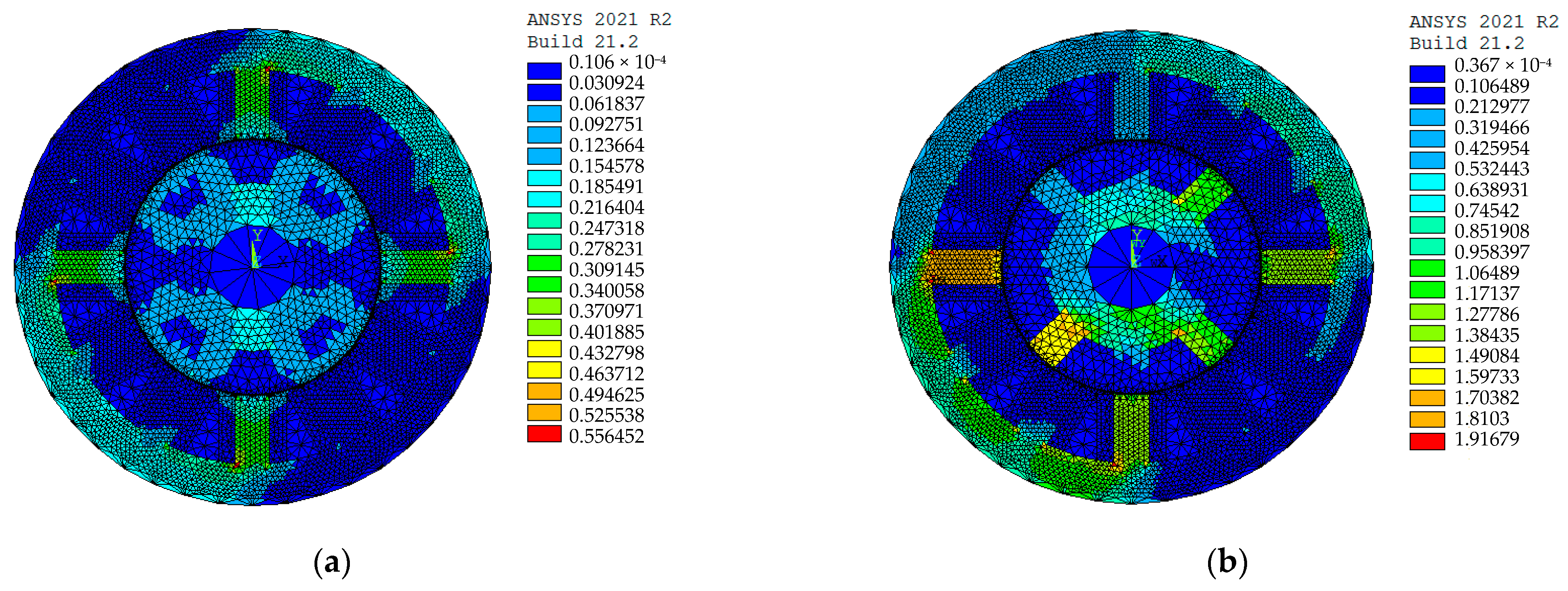
Various modeling software, including “ANSYS”, use the finite element method (FEM) for analysis. By entering the SRG 12/8 geometric parameters into the ANSYS software as mentioned in Table A1, we obtained graphical and numerical results for the flow density distribution of the SRG 12/8. Figure 2 shows the results for the extreme rotor positions, that is, the aligned and unaligned positions, under a current of 2A.
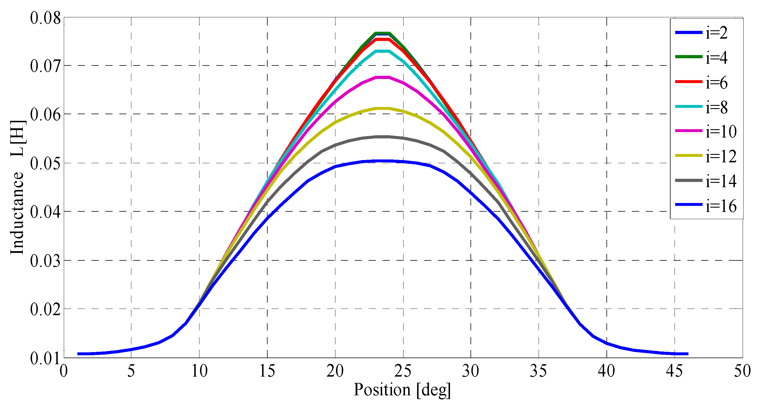
Figure 3 and Figure 4 illustrate the variations in inductance and static torque for different currents ranging from 2 A to 16 A, with a step size of 2 A. These characteristics are plotted as functions of the rotor position, transitioning from the aligned position to the non-aligned position, and then back to the aligned position.
Figure 5 illustrates a three-phase dynamic SRG model based on the previous integrated model [21]. The proposed dynamic model enables estimation of the instantaneous torque at the level of the mechanical component using the measured phase current and the static characteristics. The overall torque is computed as the sum of the output torques from each phase.
The power conversion equation, for single-phase operation of SRG, can be obtained by employing Equations (3) and (4), assuming that the resistive-voltage drop in the SRG windings is negligible. When the excitation phase concludes, the phase current is determined by both the phase voltage (V) and the background EMF (e), as given by the following equation:
V e θ , i = L θ , i · d i d t
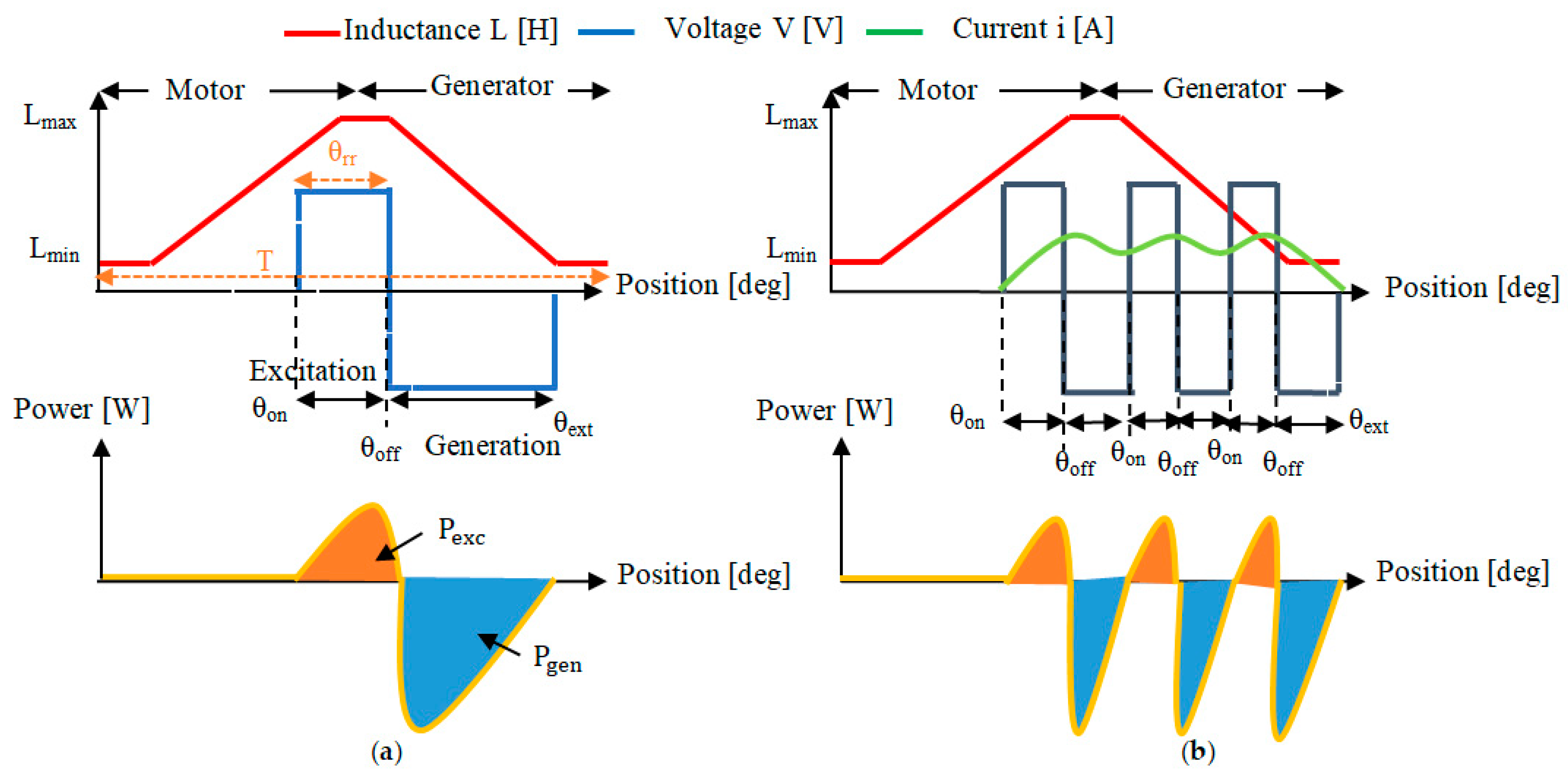
In the case of the SRG, the power conversion process relies on a transducer, as illustrated in Figure 6. This transducer serves the dual purpose of functioning as an excitation source and a storage element. To achieve excitation, the stator windings receive a series of current pulses at fixed intervals, governed by control parameters θon and θoff, which are synchronized with the inductance curve shown in Figure 7. The power and electric current within the SRG can exist in three distinct states.
Figure 6a represents the principle diagram of the state of excitation, showcasing the conversion of electrical energy into electromagnetic force. In Figure 6b, the circuit diagram for the electromagnetic-force generation state is depicted, and Figure 6c illustrates the circuit phase structure. These figures provide valuable insights into the power conversion process within the switched reluctance generator and the associated components and stages involved.
On the other hand, Figure 7 shows the reversal of the machine during the phases of increase and/or decrease in the inductance, L. The consequence will give the required operating speed:
  • Motor mode: (Te > 0) corresponds to the increasing stage of the inductance ((dL/dθm) > 0);
  • Generator mode: (Te < 0) corresponds to the decreasing stage of the inductance ((dL/dθm) < 0).
The torque of the SRG can be controlled by adjusting the substitution angles θon and θoff, as described in Figure 7.
In Figure 7a, the normal case is depicted, where the switch is opened and closed once, which produces a single current pulse being applied to the stator windings, leading to a single torque output.
In Figure 7b, a static switch is used to open and close at multiple times. This operation produces several current pulses, which will be applied to the stator windings, thus causing several torque outputs. This allows for more precise control of the output torque and also increases the complexity of the control system.
For a given phase, its electrical power, Pph, represents the sum of the powers in the generation and excitation stages. In the single-pulse mode, the generation and excitation powers of the SRG are calculated as follows:
P j = 1 T 0 T V · i j · d t : j = 1 , 2 , 3 .
P e x c = m θ r r θ o n θ o f f V · i e x c · d θ
P g e n = m θ r r θ o f f θ e x t V · i g e n · d θ
where Pj is the phase power; Pexc and Pgen are the excitation power and the power generated, successively; iexc is the excitation current; igen is the generated current; m represents the number of phases; θrr is the polar arc of the rotor; and T is the duration of the single-phase operation.
During the time interval between θon and θoff, the electric current in the SRG increases rapidly, while the power value increases positively, resulting in a positive electromagnetic force and a positive change in the inductance ((dL/dθ) > 0), which leads to the generation of positive torque. This process is depicted in Figure 6a and represents the conversion of electrical power into mechanical.
During a period time between θoff and θext, the electric current decreases speedily while the power value increases negatively, leading to a negative electromagnetic force and negative variation in inductance ((dL/dθ) < 0), producing a negative torque. This process is illustrated in Figure 6b, where mechanical power is converted into electrical.
When θ is greater than θext, the electric current and the energy become zero due to the values of the electromagnetic force and the variation in the inductance, which corresponds to zero ((dL/dθ) = 0). As a result, the torque becomes equal to zero.

3. Data Extraction of the SRG Characteristics

Data extraction is important for analysis as it allows for the gathering and processing of relevant information, which can then be used to make informed decisions and identify patterns or trends.
To assess the power generation capability of the SRG system, the output electrical power Pe is used as the performance metric. The efficiency of the SRG, which relates the electrical power output to the mechanical input force, can be determined using Equations (16) and (17) as follows [37]:
P e = P e x c + P g e n
Mechanical input power Pm can be deduced from Equation (6) and it is expressed as follows:
P m = j = 1 3 T e j ( θ , i ) · ω
where Te stands for torque load; ω stands for rotor speed.
The electrical output power is denoted by Pe; thus, the efficiency of the system can be expressed [38]:
η % = P e P m
Methods for determining the optimal parameters of an SRM have been previously presented in works [21,36,39]. The outcomes yielded positive results, and their effectiveness can be further enhanced through the utilization of intelligent algorithms. In this work, we demonstrate the manner to calculate simultaneously the input mechanical power and the output electrical power to determine efficiency. The originality of this work lies in the use of a dynamic SRG model with nonlinear magnetic properties. An algorithm has been developed to reduce torque ripple. The proposed approach achieves impressive results in a short time and highlights the valuable change in efficiency, mechanical power, and electrical power for the two angle values.
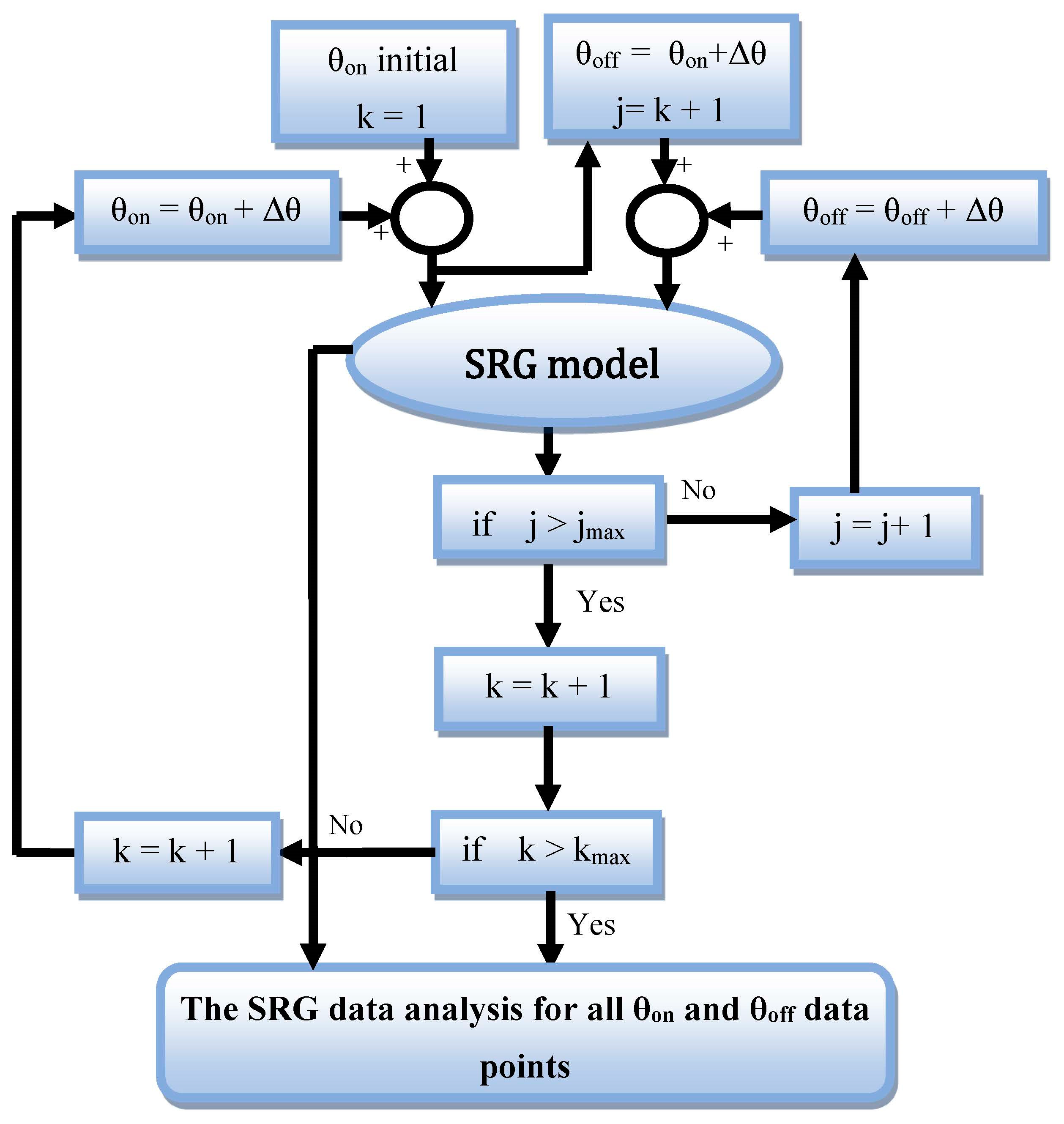
The applied method is depicted in a flowchart in Figure 8, achieved by integrating the algorithm into the control system.
The SRG operates with high speed and high torque. Its control must be optimized to reduce torque ripple by controlling the start and stop angles based on rotor position. References [13,29,40] show the importance of the turn-on (θon) and the turn-off (θoff) angles in achieving high efficiency in both cases: motor and generator modes; however, these results can be further improved by using smart algorithms to determine the optimal angles. As illustrated in references [17,38,41], algorithms can improve the calculation of efficiency by changing the angle between θon and θoff.
This paper presents an algorithm that utilizes Equations (13)–(15) sequentially to determine the efficiency of the system. The algorithm is developed using a dynamic SRG model with nonlinear magnetic properties and incorporates a proposed strategy in order to optimize both electrical power and efficiency.
The used technology allows us to obtain reliable results in a short time, with a significant increase in efficiency achieved by increasing the mechanical and electrical powers from two points of view.
Figure 8 shows the flowchart of the proposed method and the combination between the algorithm and the control system.

4. SRG Data for Power Performance

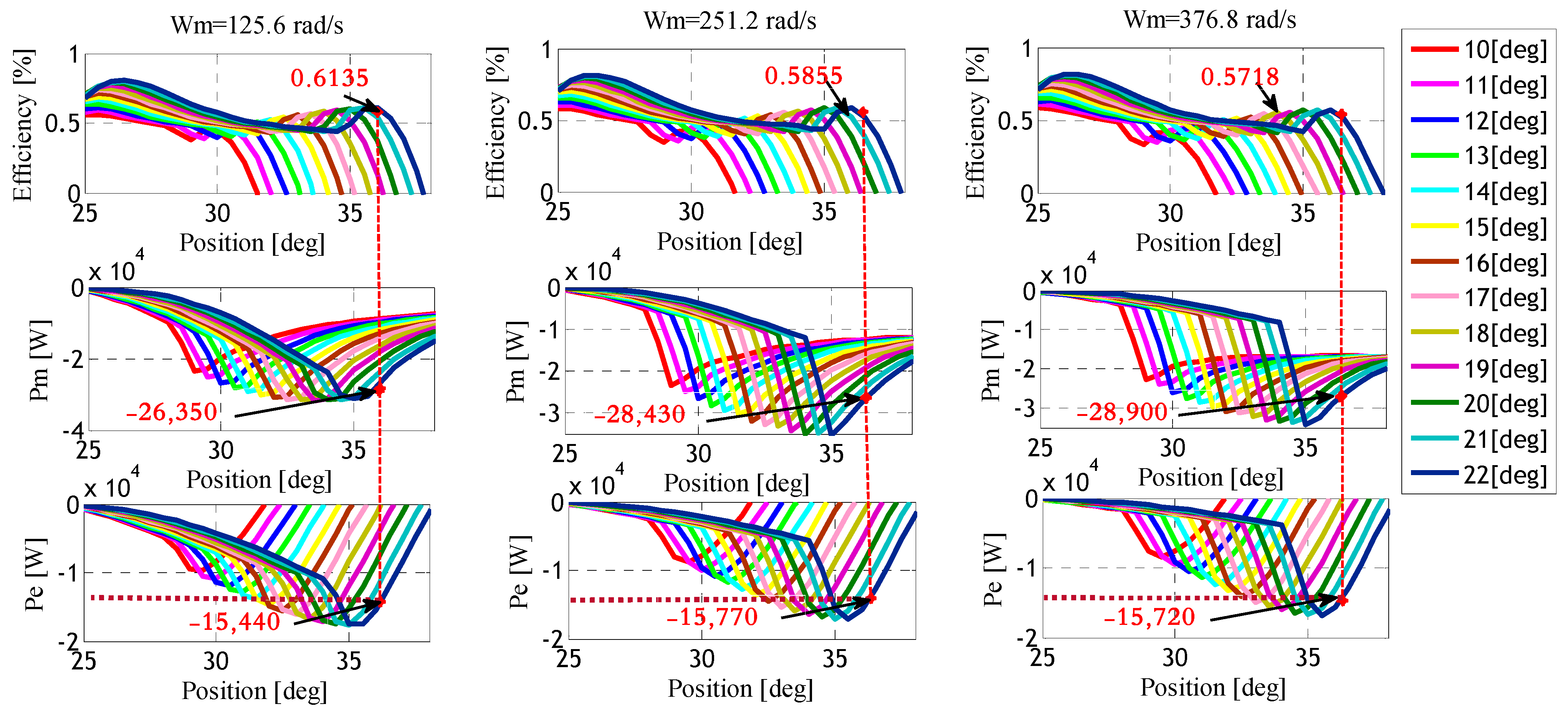
Curves obtained by simulating the dynamic SRG model using the algorithm presented in Figure 8 are illustrated in Figure 9. The dynamic SRG model was tested under different reference speeds, varied by adjusting the starting and/or stopping angles. The objective was to identify the optimal reference parameters that would result in maximum efficiency. The data are extracted at each reference speed, using the optimum start and stop angles.
The data are determined at angles: θon = 22 [deg] and θoff = 40 [deg]. The obtained results make it possible to achieve the highest values, namely mechanical or electrical powers, with better efficiency. This determines the reference speed that produces the most power of the SRG generation. Table 1 summarizes the SRG data samples collected at θon = 22 [deg] and at θoff = 36 [deg], under different conditions.
Based on the data presented in Table 1, the impact of varying the reference speed and operating angles on the SRG efficiency was analyzed. As it is seen, the efficiency decreases at higher reference speeds, given the value of 57.18% at a reference speed corresponding to 378.8 (rad/s). At an average reference speed corresponding to 251.2 (rad/s), the efficiency reaches the value of 58.55%. The highest efficiency, corresponding to 61.35%, was achieved at a reference speed of 125.6 (rad/s).
Comparing standard parameters and the data for the power performance of the SRG, this system demonstrates its capability to enhance efficiency by searching for optimal input and output parameters such as reference speed, turn-on and turn-off angles, and mechanical power. By optimizing these parameters, the SRG can achieve higher levels of efficiency and electrical power output.

5. SRG Power Efficiency

The system is sensitive to changes in operating angles. The efficient operation of the SRG depends on identifying the optimal starting and stopping angles, which are critical to achieving high mechanical and electrical power output; therefore, it is necessary to determine these angles to maximize the efficiency of the SRG.
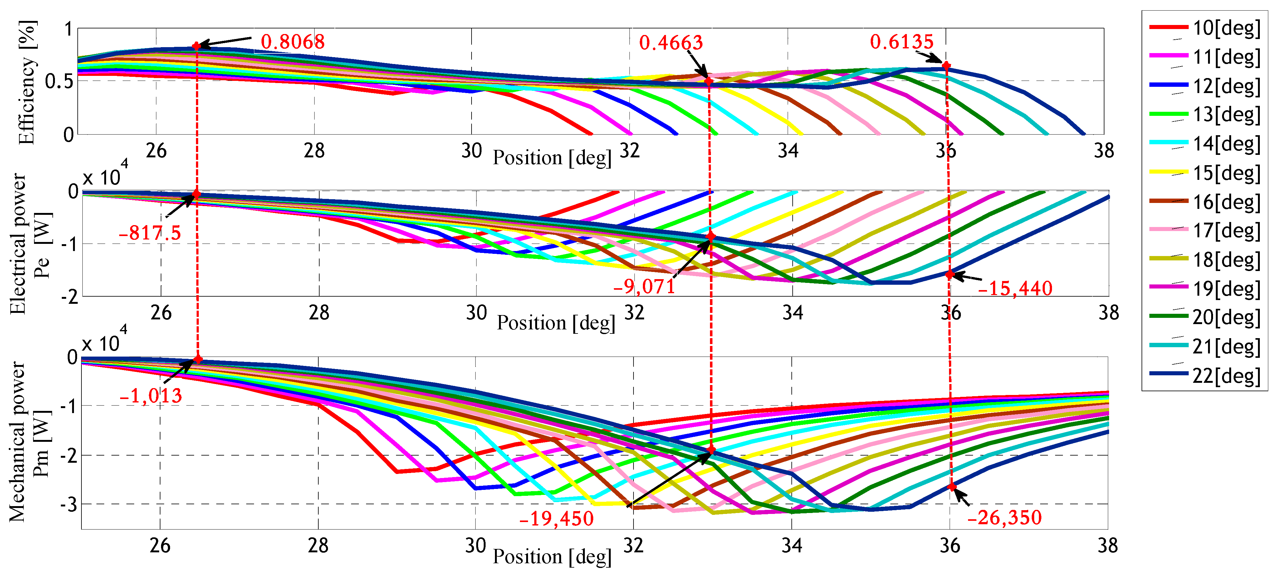
Figure 10 shows the dependence of the efficiency (%), the SRG output electrical power, and the input mechanical power with different generation modes of operating angles θ [deg] at a reference speed of 125.6 (rad/s). Table 2 summarizes the experimental data and different operating parameters at a reference speed of 125.6 (rad/s).
As can be seen, at the operating angles, θon = 22 [deg] and θoff = 26.5 [deg], efficiency reaches the highest rate, which corresponds to 80.68%; the power value is lower because the reference of the mechanical power is equal to a value of −1013 [W] and the value of electrical power is equal to −817.5 [W].
When the turn-off angle (θoff) is increased to 33 [deg] and the turn-on angle (θon) is activated at 22 [deg], the system reaches a maximum efficiency of 46.63%, which can be attributed to the augmentation in mechanical and electrical powers. Specifically, the mechanical power output Pm reaches the value of −19,450 [W], and the electrical power output Pe reaches the value of −9071 [W].
It is necessary to note, that when the values of the stopping angle θoff and the operating angle θon are equal to 36 [deg] and to 22 [deg], successively, the maximum efficiency ratio recorded for the system is 61.35%; furthermore, the mechanical power reference reaches its peak at Pm = −26,350 [W], while the corresponding electrical power achieved a value of Pe = −15,440 [W].
We conclude that the optimum operating angles cause the SRG to produce the most power when θon = 22 [deg] and θoff = 36 [deg].

6. MPPT Algorithm for the SRG

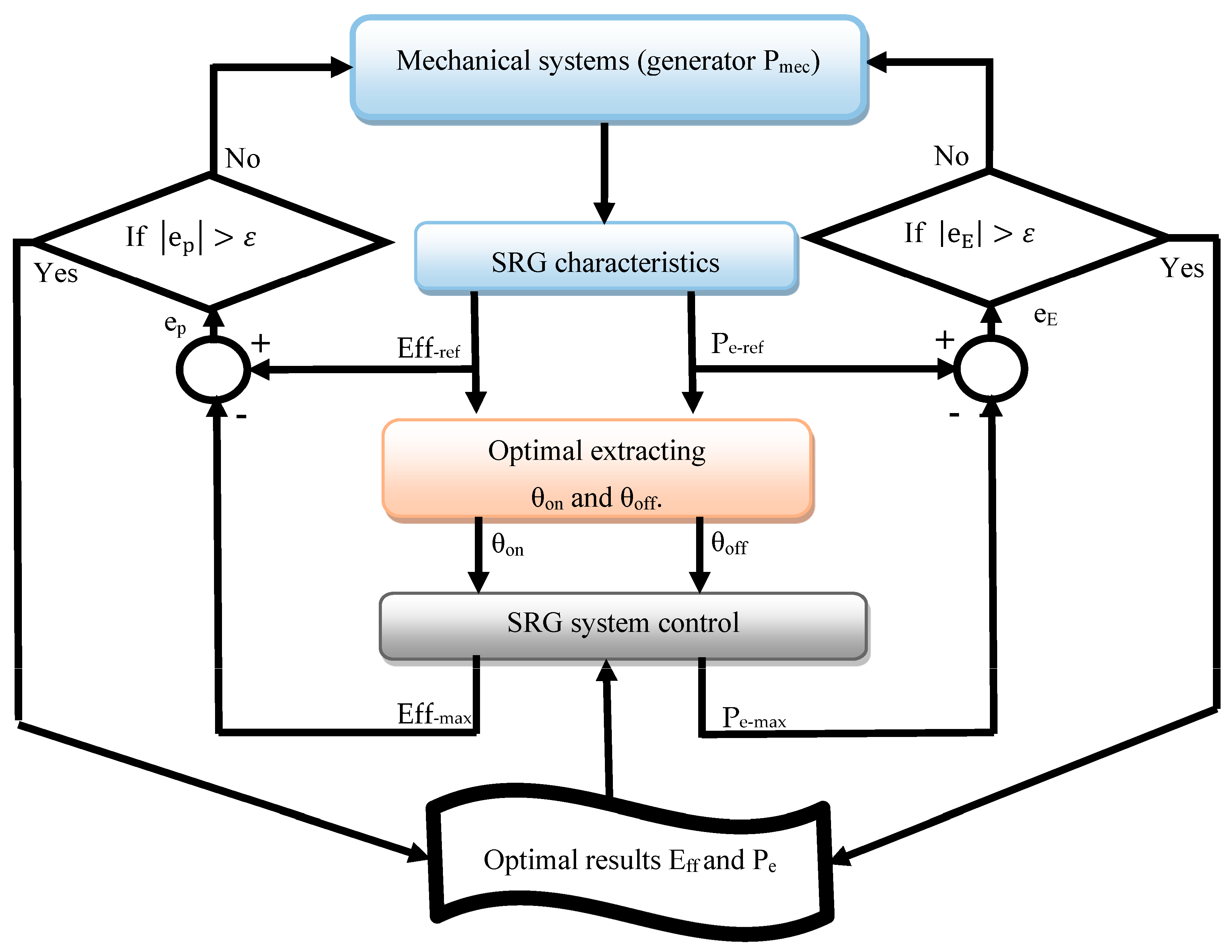
The aim is to achieve the highest values of performance and efficiency in the production of electrical energy in the case of the SRG; several studies have been carried out in this direction [32,42]. Some researchers have succeeded in having optimal values of the parameters for the functioning of the SRG. Through the use of intelligent algorithms, this research aims to identify the optimal operating angles as well as the reference value of the mechanical power of the turbine. The proposed strategy, as depicted in Figure 11, employs a new algorithm that rapidly provides accurate results and facilitates the determination of the optimal values for the SRG operation, leading to an increase in efficiency and greater electrical power generation.
First, the algorithm uses the SRG characteristics obtained from a previous algorithm to input a set of values for the mechanical power of a reference turbine. The intersection of the mechanical power between the reference values of the turbine and the characteristics of the SRG are used to obtain the maximum reference efficiency, and the electrical power reference values, to determine the optimal operating angles θon and θoff. Then, the optimum angles are entered into the SRG operating system to achieve the greatest electric power and high efficiency. The results are compared to the optimal reference characteristics.
If the difference between the reference values and the output values—extracted from the control system of the SRG—for the electrical power and efficiency is not zero, it is concluded that the results obtained from the control and operating system are not maximum, so the reference values of the turbine change and the mechanical power is returned. This process is repeated until the difference between the output values and the reference values of the aforementioned parameters is zero.
In this case, it is concluded that the values obtained represent the optimal result sought. In concrete terms, the algorithm produced allows researchers and users of SRG machines to have reference values for mechanical power and operating angles. The optimal result obtained helps in the control of the SRG system and in the production of the greatest value of electrical power.
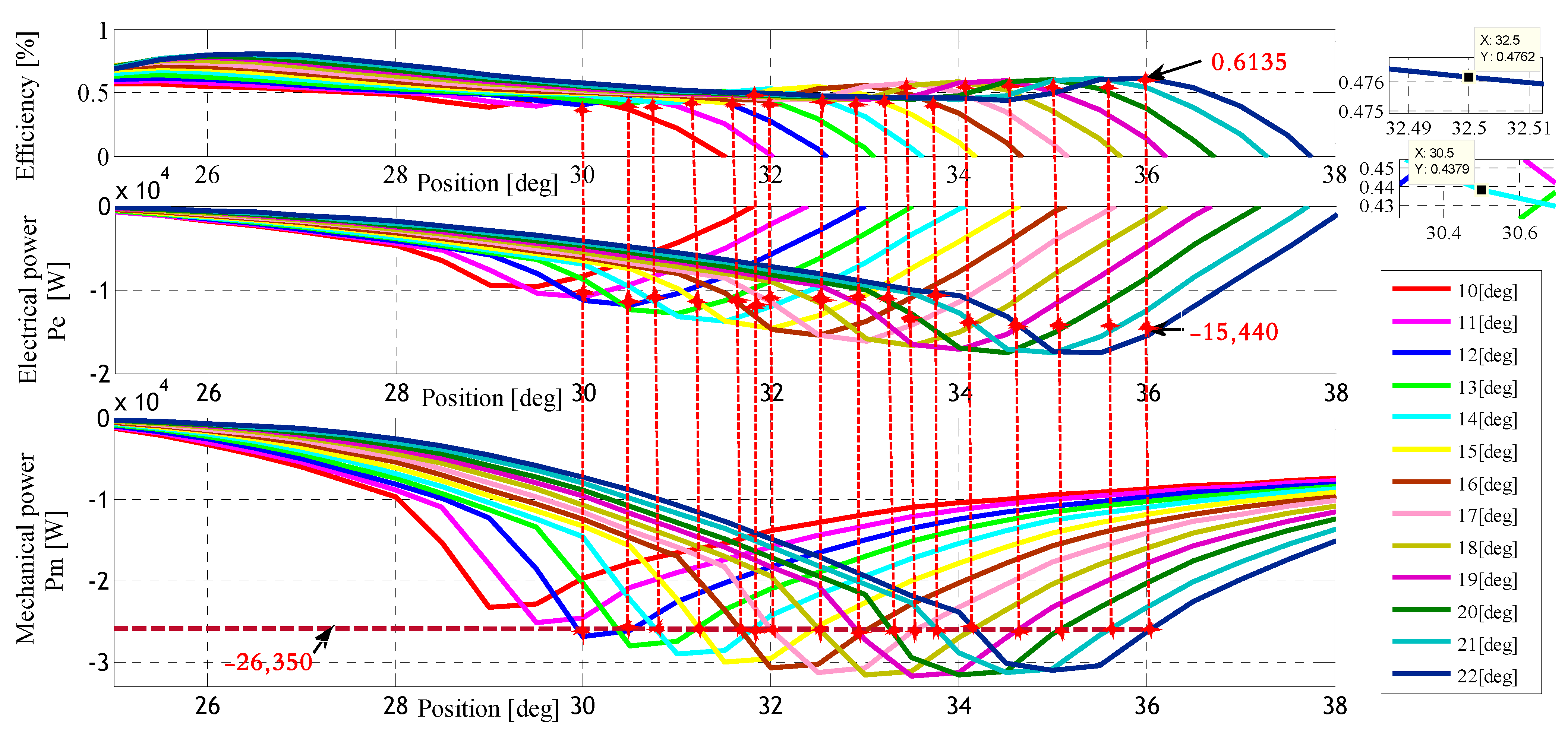
Figure 12 illustrates the implementation of the proposed MPPT technique for SRG when the reference mechanical power remains constant. By analyzing the figure, the optimal values of efficiency and electrical power can be determined at the intersection of the input mechanical power curve, with a reference value of Pm at the value −26,350 [W]. These optimal values were derived from Figure 12 and subsequently summarized in Table 3. The figure was generated to explore the optimum efficiency for the application of the MPPT technique, considering an imposed mechanical power reference of Pm = −26,350 [W].
According to the results presented in Table 3, when the reference mechanical power is set to Pm = −26,350 [W], the ideal efficiency is calculated to be 61.35%. This case indicates the efficiency achieved by the system under optimal operating conditions; additionally, the maximum electrical power obtained is Pe = −15,440 [W], which represents the highest achievable power output by the system.
The optimum operating angles θon and θoff, which give the highest efficiency and maximum electrical power, are 22 [deg] and 36 [deg], respectively. These angles determine the starting and stopping points of the SRG and play a crucial role in achieving the desired performance.
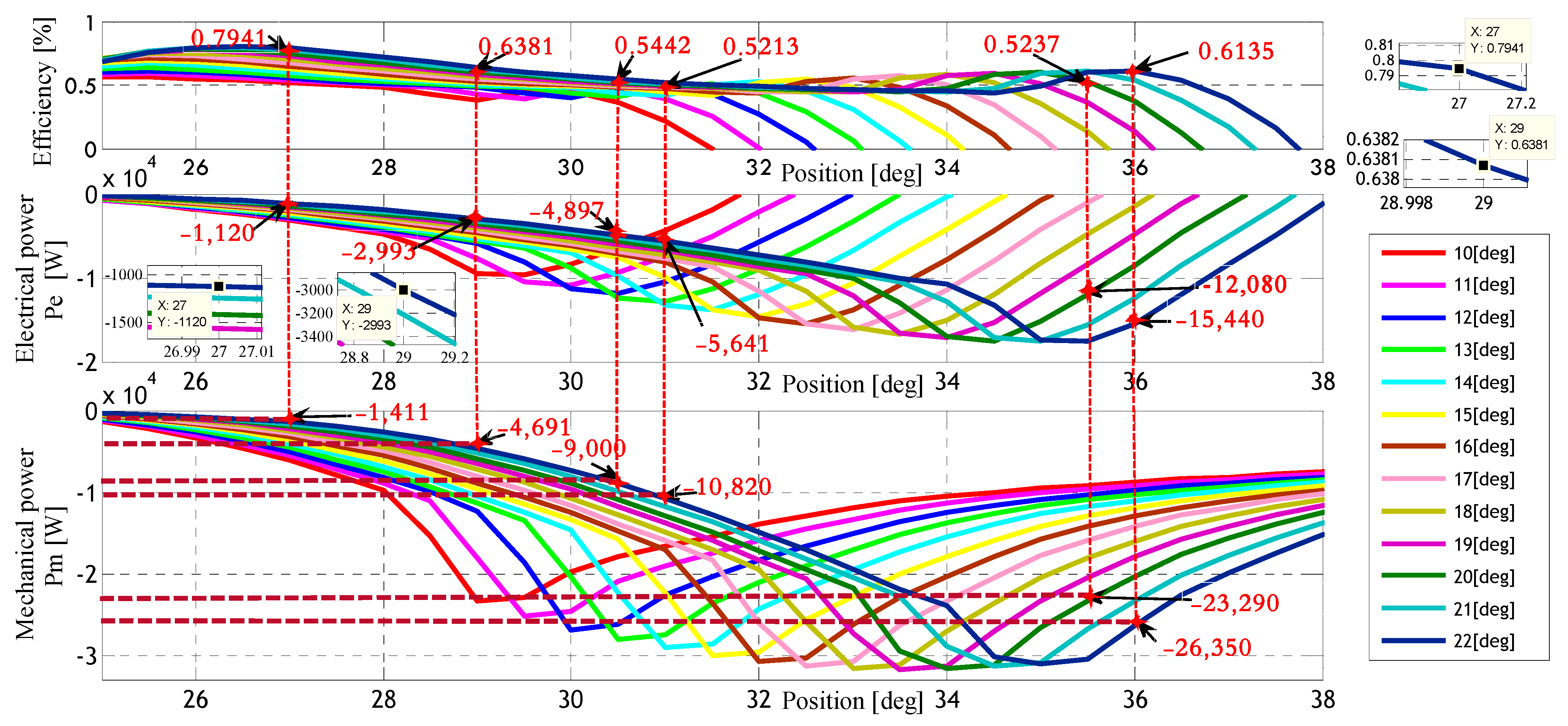
Table 4 summarizes the results obtained by applying the algorithm, which integrates the proposed MPPT technique. These results are extracted from Figure 13 with a fixed reference speed of 125.6 rad/s. Similarly, it illustrates how changing the input mechanical power based on the switching angles affects the efficiency of the SRG and the output electrical power.
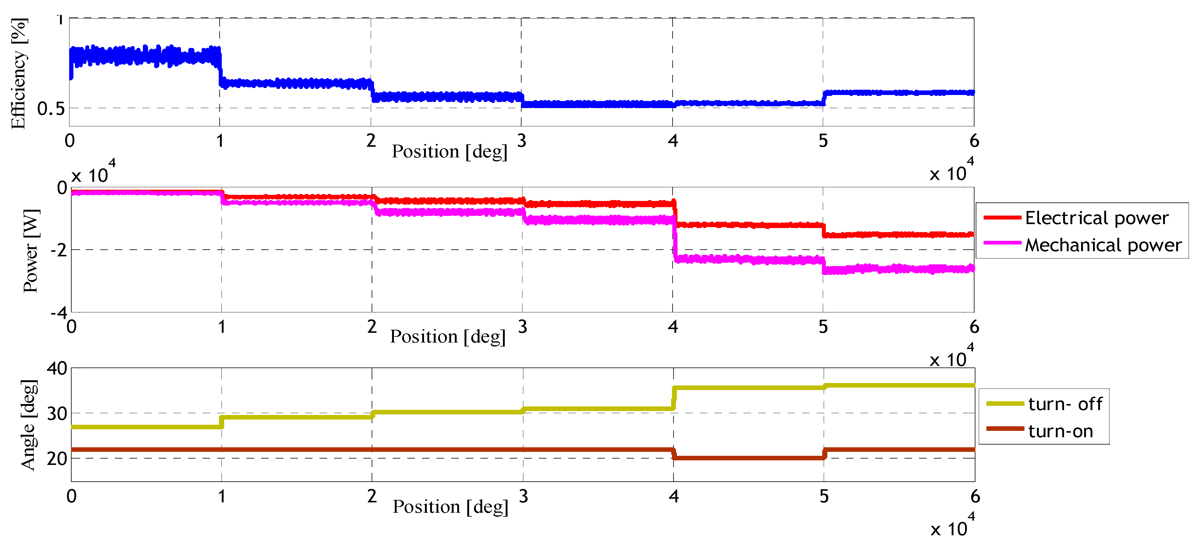
To verify the findings in Table 4, the SRG control system was operated using the reference parameters, operating angles, and mechanical strength of the input mechanical power.
By observing Figure 14, it is evident that the optimal electrical power value was achieved when the operating angles were set at θon = 22 [deg] and θoff = 36 [deg]; additionally, this optimal electrical power value was attained with a reference mechanical power of Pm = 26,350 [W].
In this study, an algorithm was used to extract the optimal reference parameters from the SRG. The parameters identified using this algorithm are the reference mechanical power of the turbine, which is equal to −26,350 [W], as well as the optimal commutation angles θon and θoff, whose values are, successively, 22 [deg] and 36 [deg]. These results made it possible to have an optimal efficiency estimated of 61.35%, and an estimated value of the electrical power of Pe = −15,440 [W].
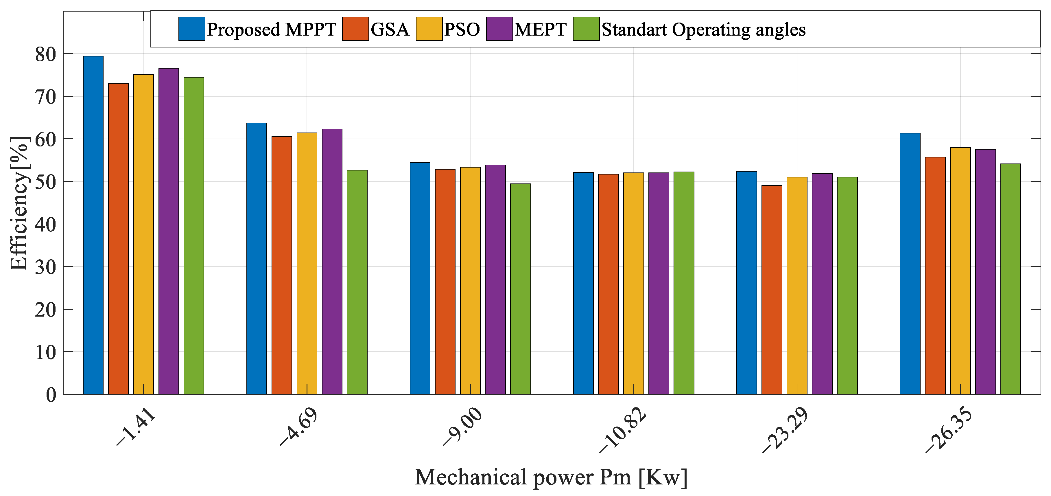
The comparisons of the proposed MPPT technique with GSA, PSO, MEPT, and standard operating angles in the SRG are presented both numerically in Table 5 and graphically in Figure 15. The results highlight the efficiency and electrical power performance for various inputs of mechanical power levels. Each technique determines the switched angles (θon, θoff) of the switched reluctance generator (SRG), with specific details provided for the GSA and PSO techniques in [32], and the MEPT technique in [31]. The use of standard parameters with fixed switching angles (θon, θoff) without optimization is of great importance in demonstrating the impact when comparing the optimized control parameters [21,29].
The presented results demonstrate the effectiveness of the proposed MPPT technique, primarily due to its reliance on all available data on the SRG efficiency under various conditions. This comprehensive approach allows the proposed MPPT to consider a wider range of performance scenarios, leading to more optimal solutions for (θon, θoff).
In comparison, the metaheuristic algorithms (GSA and PSO) search for optimal solutions for (θon, θoff) without necessarily determining whether these solutions are the best possible or if better alternatives exist. While these techniques provide good solutions, their inability to explore all potential configurations might limit their capability to discover the absolute best solution.
Similarly, the second technique, MEPT, also offers good solutions but has a limitation; MEPT is restricted to a specific range between the two switched angles (θon, θoff). This constraint may prevent it from searching for even better solutions beyond that specific stretch.
The results presented in Table 5 strongly support the effectiveness of the proposed MPPT technique in improving the overall performance of the SRG. By considering a comprehensive dataset and exploring a wider range of possibilities, the proposed technique outperforms the metaheuristic algorithms and conventional techniques.

7. Conclusions

This paper presents a new method that contributes to simultaneously leveling and maximizing the power performance and efficiency of a switched reluctance generator with respect to variable inputs of mechanical power by using MPPT techniques. The SRG model is informed by the flux–torque correlation of the generator and is calculated by nonlinear FEM to take into account its nonlinear magnetic behavior. Graphical and numerical results provide a more realistic representation of physical reality. The article also describes a correlation algorithm that allows the efficient extraction of the reference speed and the optimal commutation angle for the maximum output power of the SRG.
The algorithm under study has been implemented to determine the optimal parameters for various inputs of mechanical power conditions, with the aim of achieving the optimal operating parameters for maximum power point tracking (MPPT). To accomplish this, the reference power values were compared to the optimal values for the SRG characteristics.
The proposed MPPT technique was rigorously compared with various techniques and optimization methods, including GSA, PSO, and MEPT, as well as standard operating angles. Through this comparison, the proposed MPPT approach consistently outperformed other methods, achieving the highest levels of electrical power and efficiency for the switched reluctance generator. By leveraging comprehensive data and accurate modeling techniques, the proposed algorithm determined the optimal switching angles that led to maximum efficiency and output power. This validation reinforces the significance of the proposed MPPT technique in enhancing the overall performance of an SRG and its potential for practical applications in power-generation systems.

Author Contributions

Conceptualization, M.Z. and C.L.; methodology, M.Z., C.L., M.I., K.S. and M.B.; software, M.Z. and C.L.; validation, M.Z., C.L., M.I., K.S. and M.B.; formal analysis, M.Z., C.L., M.I., K.S. and M.B.; investigation, M.Z. and C.L.; writing—original draft preparation, M.Z.; writing—review and editing, M.Z., C.L., M.I., K.S. and M.B. All authors have read and agreed to the published version of the manuscript.

Funding

This research received no external funding.

Data Availability Statement

Not applicable.

Conflicts of Interest

The authors declare no conflict of interest.

Appendix A

Table A1. Switched reluctance generator characteristics.
CharacteristicsValues
SRM Ns/Nr12/8
Polar arc of the stator βs15.28 [deg]
Polar arc of the rotor βr15.48 [deg]
Stator outer radius69.50 mm
Inside radius of stator cylinder head57.50 mm
Inside radius of stator37.50 mm
Rotor outer radius37.00 mm
Rotor cylinder head outer radius24.50 mm
Shaft radius12.50 mm
Active length110.00 mm
Number of series on turns/phase50.00

References

  1. Kumar, B.; Sandhu, K.S.; Sharma, R. Comparative analysis of control schemes for dfig-based wind energy system. J. Inst. Eng. India Ser. B. 2021, 103, 1–20. [Google Scholar] [CrossRef]
  2. Sunan, E.; Kucuk, F.; Goto, H.; Guo, H.J.; Ichinokura, O. Three-phase full-bridge converter controlled permanent magnet reluctance generator for small-scale wind energy conversion systems. In Proceedings of the 2014 IEEE PES Asia-Pacific Power and Energy Engineering Conference (APPEEC), Kowloon, Hong Kong, China, 7–10 December 2014. [Google Scholar]
  3. Ayodele, T.R.; Ogunjuyigbe, A.S.O.; Adetokun, B.B. Optimal capacitance selection for a wind-driven self-excited reluctance generator under varying wind speed and load conditions. Appl. Energy 2017, 190, 339–353. [Google Scholar] [CrossRef]
  4. Mohanty, P.; Bhuvaneswari, G.; Balasubramanian, R.; Dhaliwal, N.K. MATLAB based modeling to study the performance of different MPPT techniques used for solar PV system under various operating conditions. Renew. Sustain. Energy Rev. 2014, 38, 581–593. [Google Scholar] [CrossRef]
  5. Eltamaly, A.M. A novel musical chairs algorithm applied for MPPT of PV systems. Renew. Sustain. Energy Rev. 2021, 146, 111135. [Google Scholar] [CrossRef]
  6. Chen, H.; Xu, D.; Deng, X. Control for power converter of small-scale switched reluctance wind power generator. IEEE Trans. Ind. Electron. 2020, 68, 3148–3158. [Google Scholar] [CrossRef]
  7. Dos Santos Barros, T.A.; dos Santos Neto, P.J.; Nascimento Filho, P.S.; Moreira, A.B.; Ruppert Filho, E. An approach for switched reluctance generator in a wind generation system with a wide range of operation speed. IEEE Trans. Power Electron. 2017, 32, 8277–8292. [Google Scholar] [CrossRef]
  8. Viajante, G.P.; Andrade, D.A.; Chaves, E.N.; Bernadelli, V.R.; Queiroz, C.A.; Freitas, M.A.A.; Gomes, L.C. A grid connection scheme of a switched reluctance generator for active power injection using P-resonant (P-RES) controller. Electr. Power Syst. Res. 2016, 141, 572–579. [Google Scholar] [CrossRef]
  9. Hasanien, H.M.; Muyeen, S.M. Speed control of grid-connected switched reluctance generator driven by variable speed wind turbine using adaptive neural network controller. Electr. Power Syst. Res. 2012, 84, 206–213. [Google Scholar] [CrossRef] [Green Version]
  10. Li, S.; Zhang, S.; Habetler, T.G.; Harley, R.G. Modeling, design optimization, and applications of switched reluctance machines—A review. IEEE Trans. Ind. Appl. 2019, 55, 2660–2681. [Google Scholar] [CrossRef]
  11. Daldaban, F.; Buzpinar, M.A. Pulse injection-based sensorless switched reluctance motor driver model with machine learning algorithms. Electr. Eng. 2021, 103, 705–715. [Google Scholar] [CrossRef]
  12. Li, Z.; Wang, X.; Zhang, L.; Du, L.; Wang, Q. Magnetic field analysis and iron loss calculation of a special switched reluctance generator. J. Electr. Eng. Technol. 2019, 14, 1991–2003. [Google Scholar] [CrossRef]
  13. Kushwaha, A.; Kanagaraj, R. Peak-current estimation using simplified current-rise model of switched reluctance generator operating in single-pulse mode. Int. J. Electr. Power Energy Syst. 2020, 120, 105971. [Google Scholar] [CrossRef]
  14. Chirapo, K.A.C.; Oliveira, A.L.; Sguarezi Filho, A.J.; Pelizari, A.; Di Santo, S.G.; Costa, E.C.M. P+ res controller applied to the direct power control of switched reluctance generator. J. Control Autom. Electr. Syst. 2020, 31, 360–366. [Google Scholar] [CrossRef]
  15. Ćalasan, M.P.; Vujičić, V.P. A robust continuous conduction mode control strategy of switched reluctance generator for wind power plant applications. Electr. Eng. 2017, 99, 943–958. [Google Scholar] [CrossRef]
  16. Scalcon, F.P.; Fang, G.; Volpato Filho, C.J.; Gründling, H.A.; Vieira, R.P.; Nahid-Mobarakeh, B. A Review on Switched Reluctance Generators in Wind Power Applications: Fundamentals, Control and Future Trends. IEEE Access 2022, 8, 69412–69427. [Google Scholar] [CrossRef]
  17. Sun, Q.; Wu, J.; Gan, C. Optimized direct instantaneous torque control for SRMs with efficiency improvement. IEEE Trans. Ind. Electron. 2020, 68, 2072–2082. [Google Scholar] [CrossRef]
  18. Deng, X.; Mecrow, B.; Wu, H.; Martin, R. Design and development of low torque ripple variable-speed drive system with six-phase switched reluctance motors. IEEE Trans. Energy Convers. 2017, 33, 420–429. [Google Scholar] [CrossRef] [Green Version]
  19. Labiod, C.; Kamel, S.; Belkacem, M.; Benchouia, M.T.; Benbouzid, M.E.H. Analyze of non-linearity effects of 8/6 switched reluctance machine by finite elements method. In Proceedings of the 2018 International Conference on Communications and Electrical Engineering (ICCEE), El Oued, Algeria, 17–18 December 2018. [Google Scholar]
  20. Srairi, K.; Feliachi, M. Numerical coupling models for analyzing dynamic behaviors of electromagnetic actuators. IEEE Trans. Magn. 1998, 34, 3608–3611. [Google Scholar] [CrossRef]
  21. Salah Boughezala, M.; Srairi, K.; Labiod, C.; Chemsa, A.; Benbouzid, M.E.H. A Novel Control Technique Based on Multi-Objective Intelligent Routing Algorithms for Optimum Performances of 12/8 Switched Reluctance Motor. Int. J. Energy Convers. (IRECON) 2021, 10, 1–11. [Google Scholar] [CrossRef]
  22. Torres, J.; Moreno-Torres, P.; Navarro, G.; Blanco, M.; Nájera, J.; Santos-Herran, M.; Lafoz, M. Asymmetrical Rotor Skewing Optimization in Switched Reluctance Machines Using Differential Evolutionary Algorithm. Energies 2021, 14, 3194. [Google Scholar] [CrossRef]
  23. Hu, Y.; Wang, T.; Ding, W. Performance evaluation on a novel power converter with minimum number of switches for a six-phase switched reluctance motor. IEEE Trans. Ind. Electron. 2018, 66, 1693–1702. [Google Scholar] [CrossRef]
  24. Labiod, C.; Bahri, M.; Srairi, K.; Mahdad, B.; Benchouia, M.T.; Benbouzid, M.E.H. Static and dynamic analysis of non-linear magnetic characteristics in switched reluctance motors based on circuit-coupled time stepping finite element method. Int. J. Syst. Assur. Eng. Manag. 2017, 8, 47–55. [Google Scholar] [CrossRef]
  25. Furukakoi, M.; Adewuyi, O.B.; Matayoshi, H.; Howlader, A.M.; Senjyu, T. Multi objective unit commitment with voltage stability and PV uncertainty. Appl. Energy 2018, 228, 618–623. [Google Scholar] [CrossRef]
  26. Zhong, Y.; Lin, J.; Wang, L.; Zhang, H. Discrete comprehensive learning particle swarm optimization algorithm with Metropolis acceptance criterion for traveling salesman problem. Swarm Evol. Comput. 2018, 42, 77–88. [Google Scholar] [CrossRef]
  27. Feng, L.; Sun, X.; Tian, X.; Diao, K. Direct torque control with variable flux for an SRM based on hybrid optimization algorithm. IEEE Trans. Power Electron. 2022, 37, 6688–6697. [Google Scholar] [CrossRef]
  28. Feng, L.; Sun, X.; Yang, Z.; Diao, K. Optimal Torque Sharing Function Control for Switched Reluctance Motors Based on Active Disturbance Rejection Controller. IEEE/ASME Trans. Mechatron. 2023. early access. [Google Scholar] [CrossRef]
  29. Zine, M.; Chemsa, A.; Labiod, C.; Ikhlef, M.; Srairi, K.; Benbouzid, M. Coupled Indirect Torque Control and Maximum Power Point Tracking Technique for Optimal Performance of 12/8 Switched Reluctance Generator-Based Wind Turbines. Machines 2022, 10, 1046. [Google Scholar] [CrossRef]
  30. Sridharan, S.; Prabhu, V.V.; Velmurugan, P. Efficient maximum power point tracking in grid connected switched reluctance generator in wind energy conversion system: An enhanced Mayfly Algorithm transient search optimization. Energy Sources Part A Recovery Util. Environ. Eff. 2021. early access. [Google Scholar] [CrossRef]
  31. Mapa, S.; Gurumoorthy, B. Maximum power extraction from a switched reluctance generator based wind power generating system using optimization techniques. Eng. Rep. 2022, 4, 1–14. [Google Scholar] [CrossRef]
  32. Araujo, W.R.; Reis, M.R.; Wainer, G.A.; Calixto, W.P. Efficiency enhancement of switched reluctance generator employing optimized control associated with tracking technique. Energies 2021, 14, 8388. [Google Scholar] [CrossRef]
  33. Wang, S.; Hu, Z.; Cui, X. Research on novel direct instantaneous torque control strategy for switched reluctance motor. IEEE Access 2020, 8, 66910–66916. [Google Scholar] [CrossRef]
  34. Teekaraman, Y. Implementation of Control Variables to Exploit Output Power for SRGs in Single Pulse Mode Operation. Int. J. Eng. 2016, 29, 505–513. [Google Scholar]
  35. Sunan, E.; Kucuk, F.; Raza, K.S.; Goto, H.; Guo, H.; Ichinokura, O. Torque ripple minimization and maximum power point tracking of a permanent magnet reluctance generator for wind energy conversion system. J. Renew. Sustain. Energy 2013, 5, 013114. [Google Scholar] [CrossRef]
  36. Labiod, C.; Srairi, K.; Mahdad, B.; Benbouzid, M.E.H. A novel control technique for torque ripple minimization in switched reluctance motor through destructive interference. Electr. Eng. 2018, 100, 481–490. [Google Scholar] [CrossRef]
  37. Zhu, Y.; Wu, H.; Zhang, J. Regenerative braking control strategy for electric vehicles based on optimization of switched reluctance generator drive system. IEEE Access 2020, 8, 76671–76682. [Google Scholar] [CrossRef]
  38. Wanthong, N.; Ohyama, K. Effect of the excitation conditions on the power generation efficiency of a switched reluctance generator. In Proceedings of the 2021 7th International Conference on Engineering, Applied Sciences and Technology (ICEAST), Pattaya, Thailand, 1–3 April 2021. [Google Scholar]
  39. Diko, M.; Rafajdus, P.; Makys, P.; Dubravka, P.; Szabo, L.; Ruba, M. A novel concept of short-flux path switched reluctance motor for electrical vehicles. Adv. Electr. Electron. Eng. 2015, 13, 206–211. [Google Scholar] [CrossRef]
  40. Dos Santos Neto, P.J.; dos Santos Barros, T.A.; de Paula, M.V.; de Souza, R.R.; Ruppert Filho, E. Design of computational experiment for performance optimization of a switched reluctance generator in wind systems. IEEE Trans. Energy Convers. 2017, 33, 406–419. [Google Scholar] [CrossRef]
  41. Choi, D.W.; Byun, S.I.; Cho, Y.H. A study on the maximum power control method of switched reluctance generator for wind turbine. IEEE Trans. Magn. 2013, 50, 1–4. [Google Scholar] [CrossRef]
  42. Hajiabadi, H.; Farshad, M.; Shamsinejad, M. Multi-objective optimization and online control of switched reluctance generator for wind power application. Int. J. Ind. Electron. Control Optim. 2021, 4, 33–45. [Google Scholar]
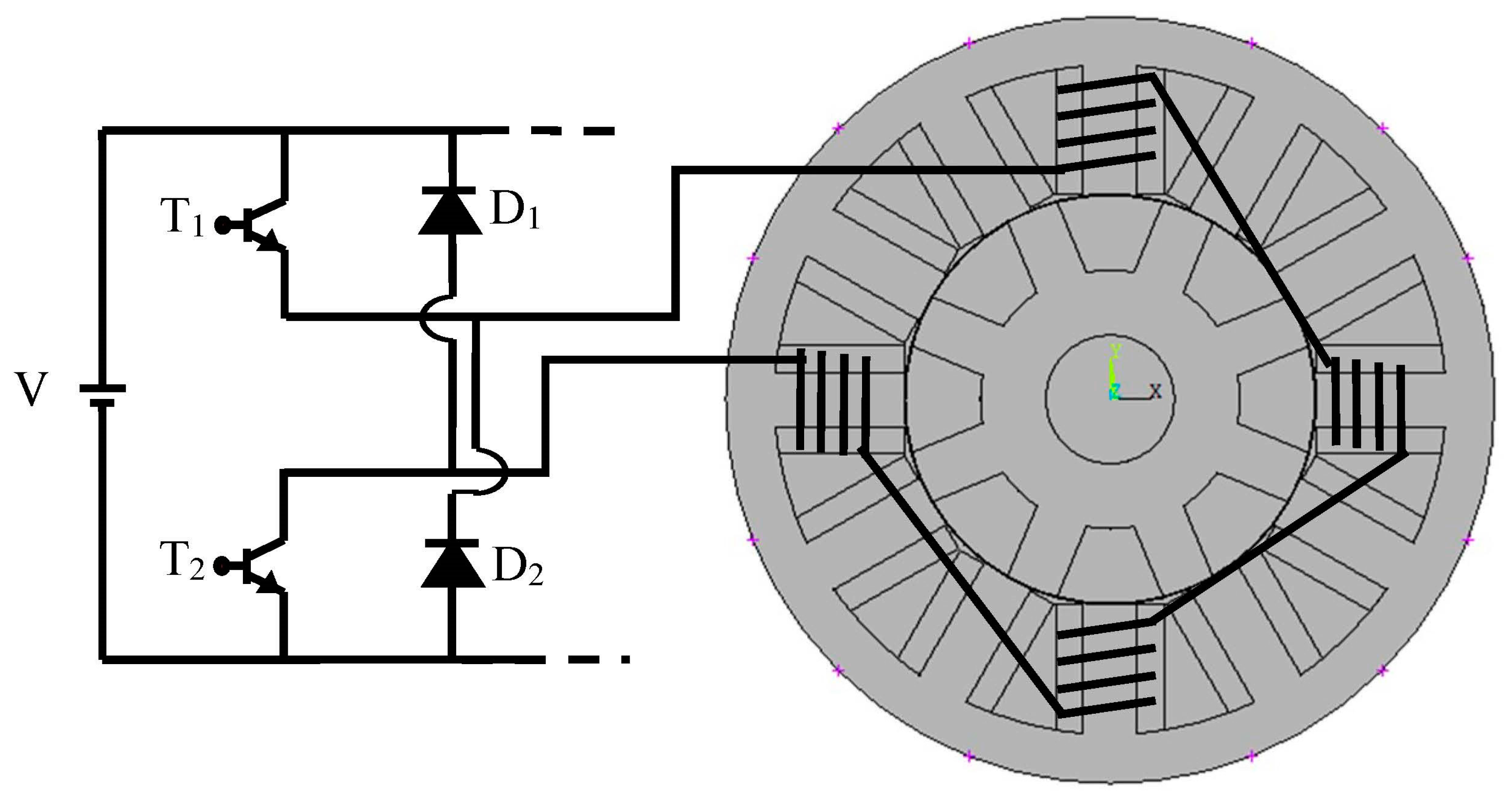
Figure 1. Synoptic scheme of 12/8 SRG machine associated with asymmetric bridge converter.
Machines 11 00816 g001
Figure 2. Flux density of 12/8 SRM in extreme position for current 2 A: (a) Unaligned position; (b) Aligned position.
Machines 11 00816 g002
Figure 3. Inductance characteristics as a function of the rotor position for currents ranging from 2 to 16 A.
Machines 11 00816 g003
Figure 4. Static torque characteristics as a function of the rotor position for currents ranging from 2 to 16 A.
Machines 11 00816 g004
Figure 5. Dynamic model of the three phases of 12/8 SRG.
Machines 11 00816 g005
Figure 6. Power-generation states of an asymmetric converter: (a) Excitation state; (b) Generating state; (c) Short-circuit state.
Machines 11 00816 g006
Figure 7. Development of power in SRG of current, inductance, and voltage waveform via the angle effect (θon, θoff): (a) Easy switching; (b) Hard switching. Where Pexc is the excitation power; Pgen is the generated power; θrr is the rotor pole arc; and θext is the extinction angle.
Machines 11 00816 g007
Figure 8. SRG data for various power modes. Where k is the number of operating angle steps; j is the number of steps of the stopping angle.
Machines 11 00816 g008
Figure 9. Graphical representation of SRGs’ power performance, depending on θon and θoff.
Machines 11 00816 g009
Figure 10. Exploration of the relationship between the efficiency (%) of SRG, the input mechanical power, and the output electrical power via the operating angles θ [deg].
Machines 11 00816 g010
Figure 11. Description of proposed MPPT technique for SRG. Where eE is the difference between two maximum and reference electrical power values of efficiency; and ep is the difference between two maximum and reference values of efficiency.
Machines 11 00816 g011
Figure 12. Using the proposed MPPT technique for SRG, the relationship in switching angles θon and θoff under the reference mechanical power condition, Pm = −26,350 W.
Machines 11 00816 g012
Figure 13. The utility of the MPPT technique to obtain the maximum electrical power and efficiency of the SRG and the relationship in switching angles θon and θoff with the change in each value of the reference mechanical power.
Machines 11 00816 g013
Figure 14. Relationship between the switching angles, θon and θoff, and the reference mechanical power to obtain both efficiency and maximum electrical power for SRG.
Machines 11 00816 g014
Figure 15. Comparison of Efficiency for MPPT, GSA, PSO, MEPT methods, and standard operating angles in SRG.
Machines 11 00816 g015
Table 1. SRG data samples collected at θon = 22 [deg] and at θoff = 36 [deg], under different conditions.
Reference speed
Wm [rad/s]
Efficiency
Eff [%]
Mechanical Power
Pm [W]
Electrical Power
Pe [W]
θon [deg]θoff [deg]
125.60 61.35−26,350−15,4402236
251.20 58.55−28,430−15,7702236
378.80 57.18−28,900−15,7202236
Table 2. Optimal efficiency for different inputs of mechanical power conditions at a speed of 125.6 (rad/s).
Efficiency
Eff [%]
Mechanical Power
Pm [W]
Electrical Power
Pe [W]
θon [deg]θoff [deg]
61.35−26,350−15,440.002236.0
46.63−19,450−9071.002233.0
80.68−1013−817.502226.5
Table 3. The optimum efficiency with electrical power under mechanical power condition. Pm = −26,350 W.
Efficiency
Eff [%]
Electrical Power
Pe [W]
θon [deg]θoff [deg]
0.3958−11,3801230.00
0.4073−11,9201230.50
0.4387−11,5601430.75
0.4315−11,88013 and 1531.25
0.4387−12,0801631.70
0.5031−12,4301431.80
0.4762−11,5401732.00
0.4469−11,5601832.50
0.4387−11,9201932.75
0.5698−14,2701733.50
0.4387−11,5602133.75
0.5853−14,70018 and 2234.10
0.5849−14,7201934.60
0.5941−14,9002035.10
0.5698−14,7202135.60
0.6135−15,4402236.00
Table 4. Switching angles (θon, θoff) obtained using the proposed MPPT technique for different input mechanical power levels.
Mechanical Power Pm [W]θon [deg]θoff [deg]Efficiency
Eff [%]
Electrical Power Pe [W]
−14112227.000.7941−1120
−46912229.000.6381−2993
−90002230.250.5442−4897
−10,8202231.000.5213−5641
−23,2902035.500.5237−12,080
−26,3502236.000.6135−15,440
Table 5. Numerical comparison of efficiency and electrical power for proposed MPPT, GS, A, PSO, MEPT methods and standard operating angles.
Pm [KW]−1.41−4.69−9.00−10.82−23.29−26.35
Proposed MPPTon, θoff)(22.0, 27.0)(22.0, 29.0)(22.0, 30.2)(22.0, 31.0)(20.0, 35.5)(22, 36.0)
Eff [%]79.4363.7554.4452.1352.3761.35
Pe [Kw]−1.12−2.99−4.90−5.64−12.08−15.44
GSA [32]on, θoff)(17.0, 26.0)(16.0, 27.7)(16.0, 29.0)(18.0, 30.0)(17.0, 34.0)(19.0, 34.6)
Eff [%]73.0560.5552.8851.6649.0755.71
Pe [Kw]−1.03−2.84−4.76−5.59−11.43−14.68
PSO [32]on, θoff)(18.0, 26.2)(17.0, 27.9)(17.0, 29.3)(19.0, 30.3)(19.0, 35.0)(20.0, 35.0)
Eff [%]75.1761.4053.33 52 5157.91
Pe [Kw]−1.06−2.88−4.80−5.62−11.88−15.26
MEPT [31]on, θoff)(19.0, 26.4)(18.0, 28.1)(19.0, 29.8)(20.0, 30.5)(20.0, 30.5)(21.0, 35.6)
Eff [%]76.5962.2653.8852.0351.8657.57
Pe [Kw]−1.08−2.92−4.85−5.63−12.08−15.17
Standard operating angleson, θoff)(20.0, 30.0)(20.0, 30.0)(20.0, 30.0)(20.0, 30.0)(20.0, 30.0)(20.0, 30.0)
Eff [%]74.4652.6649.4452.215154.15
Pe [Kw]−1.05−2.47−4.45−5.65−11.88−14.27
Disclaimer/Publisher’s Note: The statements, opinions and data contained in all publications are solely those of the individual author(s) and contributor(s) and not of MDPI and/or the editor(s). MDPI and/or the editor(s) disclaim responsibility for any injury to people or property resulting from any ideas, methods, instructions or products referred to in the content.