Abstract
Gripper finger design is a complex process that requires a lot of experience, time, and effort. For this reason, automating this design process is an important area of research that has the potential to improve the efficiency and effectiveness of robotic systems. The current approaches are aimed at the automated design of monolithic gripper fingers, which have to be manufactured additively or by machining. This paper describes a novel approach for the automated design of gripper fingers. The motivation for this work stems from the increasing demand for flexible, adaptable handling systems in various industries in response to the increasing individualization of products as well as the increasing volatility in the markets. Based on the CAD data of the handling objects, the most suitable configuration of gripper fingers can be determined from the existing modules of a construction kit for the respective handling object, which can significantly reduce the provisioning time for new gripper fingers. It can be shown that gripper fingers can be effectively configured for a variety of objects and two different grippers, increasing flexibility in industrial handling processes.
1. Introduction
The design automation of robotic gripper fingers is one of the most interesting topics to the robotics industry, as gripper fingers play an important role in the overall performance and throughput of robotic cells [1,2]. Currently, fingers are largely designed manually and the process, on the one hand, requires expert knowledge and on the other hand involves several time-consuming trial-and-error iterations in designing, manufacturing, and verifying the fingers [3]. In the context of volatile markets, increasing robotic applications, and the increasing customization of demand, manual gripper finger design can no longer meet the requirements. Research in this area of robotics has led to different types of gripper fingers that can either be adapted to a handling task by the user or can adapt autonomously.
1.1. Gripper Finger Types
Although there are now many different grippers, two-finger parallel grippers are still the most commonly used in industrial applications. The widespread use of parallel grippers in production technology can be attributed to their robustness, flexibility, and wide range of technical solutions [4,5].
Figure 1 shows different types of gripper fingers. These range from finger blanks for manual reworking to highly flexible gripper fingers that can adapt to the geometry of the workpieces during the gripping process. The more inflexible a single finger is, the more the interchangeability of the finger or finger components serves to adapt the finger to a handling task; gripper finger blanks in the form of aluminum or steel cuboids have appropriate features for connection to the gripper, but must be reworked by the user for each task [6,7]. Reconfigurable gripper fingers can be manually adjusted by positioning pins [8,9] on a die plate or changing the joint angles of multi-link fingers [10]. Modular gripper finger approaches include gripper fingers composed of modules [11] and approaches in which entire fingers can be selected from a finger collection as modules of the gripper and attached to the gripper via a standardized interface [12].
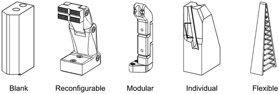
Figure 1.
Gripper Finger Types.
Through modularity, as with finger blanks, the whole finger can be adapted to a handling task by replacement. For example, interchangeable fingers were investigated early on in the research, applicable to microgrippers [13], two- and three-finger grippers [14], and grippers with integrated sensors [15]. In addition to taking into account the interchangeability of fingers for the use of application-specific gripper fingers, the number of fingers can also be changed via a standardized interface in order to increase gripping safety [16,17], especially with unknown objects, or to be able to use function-integrated fingers if required and to maintain them easily [18]. The advantage of modular gripper fingers is that the selectable fingers have already been tested and meet the specifications of the gripper. Finger geometries that can be assembled from modules offer more flexibility. The finger elements are connected to each other via a standardized interface. The user is responsible for ensuring that the designed fingers meet the specifications (e.g., length, projection) for use with a gripper [19]. In addition to the already available FiNGERKIT kit from Weiss Robotics [20], the existing approaches are limited to prototypes [11] for underactuated grippers and concepts [11]. Individual gripper fingers are usually defined, designed, and manufactured for one or a few applications and attempt to replicate the geometry of the workpiece at the gripping points to increase gripping stability. This category includes all manually designed gripper fingers, which still make up a large portion of the industrially used gripper fingers [21]. The design process of such gripper fingers is usually iterative and very time-consuming. In addition, in-depth knowledge of gripping with robots and practical experience with design methods are required. In most cases, a gripper finger design based on empirical knowledge is designed, fabricated, and physically tested. Necessary changes lead to another iteration loop in which entire fingers are remade. The use of additive manufacturing techniques leads to a shortening of the above iteration cycles. To cope with a range of object variations, so-called flexible gripper fingers can be used as an alternative to specific finger design, which passively adapt to the shape of the gripped object by using the compliance of the elastomeric materials from which they are made [22]. A distinction can be made between contact-controlled (Fin Ray Effect) and chord-controlled (underactuated grippers) deformation [23]. Flexible gripper fingers, due to the softness of the material and mechanical compliance, allow a reduction in control complexity and can be used wherever precise, force-intensive manipulations are not required [23]. However, in practice, these types of fingers are rarely used due to their lower mechanical robustness [6].
1.2. Automated Gripper Finger Design Process
The costly and time-consuming development of gripper fingers has led to the development of approaches in both research and industry that automate the process of designing gripper fingers [24]. A general overall process can be divided into five steps (see Figure 2), although the existing approaches do not cover all steps equally.
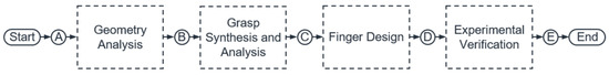
Figure 2.
General process of automated gripper finger design.
In the geometry analysis (A–B), the necessary information for the following processes of the grasp synthesis and finger design is determined. Every automated gripper finger design requires input information. This includes, for example, information about the workpiece or the gripper used. This is collected and analyzed in the first step. An important step in the development of gripper fingers is the grasp synthesis and analysis (B–C). In the context of robotics, a grasp is generally defined as the set of contacts on the object surface that prevent the potential motion of the object due to external disturbances [25]. The identification of these contacts is part of the grasp synthesis, while the evaluation of the determined grasps is part of the analysis. Finding grasps on objects can be performed based on data or analytically. While a large number of possible grasps can be found very quickly with the data-based approaches, the traceability of the grasps is not always comprehensible. Analytical approaches, on the other hand, allow the comprehensible finding of grasps, but can be very time-consuming, especially for complex handling objects. A variety of metrics, such as the Ball criterion according to [26], have been proposed by researchers to evaluate grasp quality. The step of finger design (C–D) can be very different. With regard to the types of gripper fingers described above, approaches exist for the automated design of reconfigurable [8,27], individual [5,28], and modular gripper fingers [29]. The approaches for reconfigurable fingers are limited to the arrangement of pins on a perforated plate. The design of individual gripper fingers is already commercially available [3] or is being investigated as a controllable approach in research [5,28]. In the area of modular fingers, a concept exists that has not yet been realized [29].
The experimental evaluation and verification (D–E) of the identified and generated fingers is the final step to ensure the functionality of the fingers in practice. However, in much of the previous research in this area, experimental validation is limited or not performed at all, due to the need for expensive equipment and the lack of a standardized procedure [21]. In [30], a general experimental approach was described for the first time to validate and compare the stability of grasping and the performance of fingers.
In all the described approaches of individual grasping fingers, the whole finger structure is created automatically, which requires changing the fingers when changing tasks. However, in many situations, only the modification or change of the fingertip is required, which makes the replacement of the gripper fingers or even the entire gripper uneconomical [31]. In summary, the approaches described here differ essentially in terms of provisioning time, i.e., the time to meet the demand for new gripper fingers and the guaranteed availability of gripper fingers for use, functional integration, and workpiece flexibility. While finger blanks and individual gripper fingers can be very individually adapted to handling tasks, a lot of time and knowledge are required for manufacturing. Flexible gripper fingers can adapt to different geometries during gripping, but do not (yet) meet industrial requirements. Reconfigurable gripper fingers are limited, especially in the area of adaptation possibilities, since, for example, only cantilevers can be realized. The modular approach makes it possible to adapt the gripper fingers to a certain degree to a handling task without the need for complex mechanics and controls or custom manufacturing. Another advantage is versatility, as the fingers can be disassembled and reassembled to form new combinations for new tasks. The existing approaches to the automated design of gripper fingers from modules currently exist only conceptually and require multiple iterations to derive gripper finger geometries.
1.3. Paper Contribution
This paper presents the automated configuration of application-specific gripper fingers for two-finger parallel grippers from a modular construction kit, which includes, on the one hand, the automated determination of gripping points on objects and on the other hand the creation and evaluation of different gripper finger configurations (this includes the steps from B to C and C to D in Figure 2). Based on the handling objects and the gripper selected by the user, different gripping positions on different areas of the workpiece surface are determined and evaluated. Then, kinematic chains are determined from the modules of the construction kit and evaluated based on defined criteria (e.g., projection, number of modules). Thus, without expert knowledge and without multiple iterations, gripper finger configurations can be determined that are suitable for handling the respective handling object. The solution was implemented as a prototype and tested on a real system.
1.4. Paper Organization
In the first part of the article, we explain the initial situation on which this paper is based. We describe the grasping synthesis to determine different grasping positions on handling objects. The determined grasping positions are ordered and evaluated. Based on this, the idea of automated configuration based on a kinematic chain is described and tested. This is followed by the verification of the determined configurations and the evaluation and selection of the necessary configurations for a set of handling objects.
2. Initial Situation
The automated configuration of gripper fingers from modules requires the existence of a modular construction kit from which the modules can be selected. In [32], we presented the development of a modular system for the two-finger parallel grippers on which this paper is based. The procedure for determining the modular system is based on common methods for modular product development: Starting from a definition of the requirements from the literature, among other things, the requirements are transferred into functions and the relationship between the functions is evaluated in a design structure matrix (DSM). By a reorganization of the DSM and a description of the modules, a definition of the interfaces as well as a construction of the modules is executed. This results in a construction kit consisting of nine modules (Figure 3). The modular system comprises a gripper-specific base module (A) that translates the gripper interface at the base jaw into that of the modular system. The straight modules (B) and the angled modules (C) are used to bridge the distance between the gripper and the gripping position on the workpiece. The straight module type is available in three length increments determined by geometric series. Modules C_1 and C_2 are used for cantilevers along the gripping direction, and modules C_3 and C_4 are used for cantilevers transverse to the gripping direction. Each module has a mechanical and an electrical interface (Figure 5a). The mechanical interface is used for the mechanical connection between the modules and is implemented with the SCHUNK BSWS-50 quick-change jaw system. The electrical interface supplies power to the optional sensors in the fingertip and transports the sensor signals from the sensors back to the gripper. Spring contacts with 10 pins are used for this purpose. The upper end of each finger forms the fingertip with an exchangeable active surface and the option of integrating sensor modules. A force sensor and a distance sensor are used to demonstrate the capabilities of the system. The fingertip (D) is selected by the user, so no distinction is made between different fingertips during configuration. In order to test both the construction kit and the gripping point determination, a handling object spectrum is required. The part spectrum is used for testing and offers the possibility of comparison with other approaches. Of course, the gripper finger configuration should work with as many workpieces as possible. There is only a little abstracted knowledge about the characteristics of industrially used handling objects. For the testing of grippers or gripping tasks, mostly objects of daily life are used in the literature, but they are not relevant for industrial handling processes. Following the basic geometries of workpieces described in [33] and their classification, a workpiece spectrum consisting of spherical, cylindrical, hollow, mushroom-shaped and flat parts is defined. Spherical and cylindrical workpieces can be centered with adapted contact surfaces, the design of which can be checked with these workpieces. Hollow parts can be described with external grips via their convex envelope. In their outer contour, they therefore similarly did not differ from the block parts described in [33]. Since hollow parts are often held by frictional contact, a balance must be made between sufficient gripping safety and non-destructive workpiece contact with regard to the gripping forces.
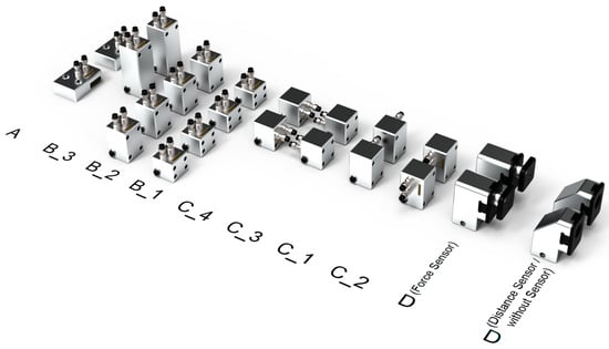
Figure 3.
Overview of the construction kit.
Hollow parts are therefore predestined for the use of force sensors in order to meet these requirements by actively controlling the gripping force. Compared to cylindrical parts, mushroom parts have similar gripping points, but they have a strongly modified interference contour and are thus suitable for validating the collision criteria in finger design. Flat parts are easy to grip due to their simple and planar outer contour. At the same time, variable finger lengths are possible. Flat parts are thus suitable for validating the requirement for short fingers. For the comparison with the automated finger design in [5], a test object is taken from this work. To represent variable dimensions, the basic shapes form the starting point of a series, which scales the workpiece dimensions over seven size levels. The size steps (numbers 1–7 in Figure 4) are created according to the geometric standard number series with the scaling factor 1.585 [34]. Figure 4 shows the workpiece spectrum.
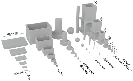
Figure 4.
Workpiece spectrum.
Given the modular system and the range of workpieces shown in Figure 4, the configuration problem is illustrated in Figure 5b. A gripper is used to handle the selection of workpieces shown in the example. It must therefore be determined where the workpieces can be gripped depending on the span and the stroke of the gripper and in which order the modules of the construction kit must be combined with each other in order to be able to grasp the workpieces.
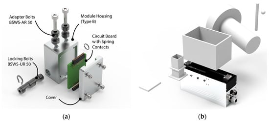
Figure 5.
(a) Exploded view of a type B module; (b) Representation of the configuration problem.
3. Grasp Synthesis and Analysis
The procedure for the automated configuration of modular gripper fingers is based on the general process (Figure 2). In the geometry analysis, user inputs are queried, stored, and used for the following steps. The focus of this paper is on the method for configuring fingers from modules. The gripping positions on the handling objects are relevant for this, which is why the grasp synthesis is discussed in more detail here.
The flowchart in Figure 6 shows the overall process of the grasp synthesis, which is described in more detail below.
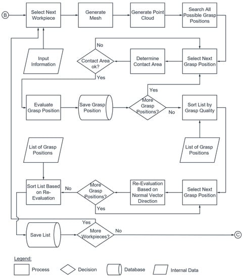
Figure 6.
Flowchart of the grasp synthesis.
In order to make the procedure of the finger configuration and grasp synthesis comprehensible, an analytical approach is followed. Starting from the STL file of a handling object, a mesh (Figure 7a) and a point cloud (Figure 7b) of the object are generated. This is followed by the identification of all grasp positions on the surface of the workpiece, where a grasp set consists of several pairs of grasp points (grasp positions). The following criteria must be met for a grasp point pair to be categorized as a grasp position for parallel jaw grippers:
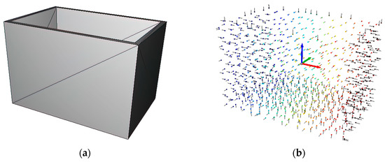
Figure 7.
(a) STL file of a handling object in the form of a mesh; (b) STL file of a handling object in the form of a point cloud.
- The contact points must be opposite each other (normal vectors directed in opposite directions);
- The surfaces on which the contact points lie must be as parallel as possible;
- The surfaces on which the contact points lie must be as flat as possible.
Each gripping position is then examined with regard to the available contact area between the workpiece and the object. The contact area available at the fingertip is 576 mm2 (24 mm × 24 mm). The previously created mesh consists of many small triangles, and each triangle can be considered a plane. Starting from the triangle in which one of the two determined points of a grasping position is located, the adjacent triangles can be checked for coplanarity with the original triangle. If coplanar, then the respective triangle is added to a common plane. This iteration continues until a triangle and the plane are no longer coplanar. Thus, the possible contact area can be determined and compared to that of the fingertip. If the contact area for both gripping points of a gripping position is sufficiently large, then the respective gripping position is evaluated in terms of grasp quality. The epsilon criterion according to Ferrari and Canny [26] is used for this purpose. According to [26], the quality of a grasp position depends on the largest disturbance wrench that can be resisted by the grasp points in all directions. This corresponds geometrically to the radius ε of the largest sphere centered on the origin and inscribed in the convex hull of the unit contact wrench. The epsilon criterion can be used to order the list of grasp positions.
The best five gripping points thus determined for the hollow part used as an example are shown in Figure 8a. The figure also shows a disadvantage of the described grasp point determination: In order to determine the minimum required number of different finger configurations for a set of handling objects, the different grasp positions should be located on different surfaces of the objects. This makes it possible that, for example, the same finger configuration can be used for the second-best grasp for object 1 and the third-best grasp for object 2. In order to adapt the grasp point determination to this, a synthetic evaluation value is determined, which weights grasp positions on other surfaces of the object more strongly. The result of the adjusted calculation is shown in Figure 8b. It can be seen that the grasp positions are now distributed over the entire workpiece and not only on two surfaces of the workpiece as in Figure 8a. This means that the solution space for the finger configuration is not already restricted in advance.
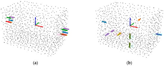
Figure 8.
(a) The best five grasp positions for an object; (b) The adjusted best five grasp positions for an object.
4. Gripper Finger Configuration
4.1. Procedure of the Gripper Finger Configuration
Figure 9 shows the procedure of automated gripper finger design from modules. The individual sections of the flow chart are described in detail below.
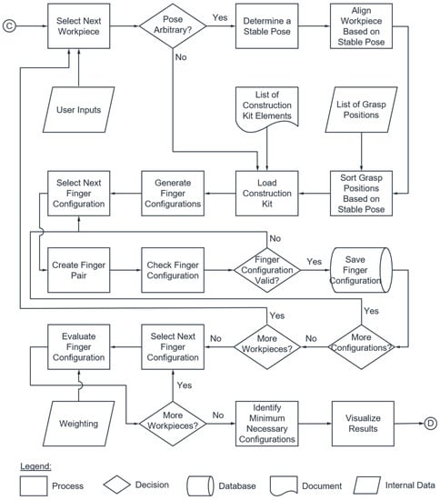
Figure 9.
Flowchart of the finger design.
4.2. Stable Workpiece Pose
If the pose of the workpiece is not defined by the user, then a stable workpiece pose must be determined. In [35], the preferred orientation of handling objects is formulated by the maximum tilt angle, which simultaneously maximizes the pose stability and the ordering probability. Therefore, it is assumed that the object is provided in the preferred orientation.
Figure 10 shows the definition of the tilt angle χ for a pose in terms of workpiece geometry and center of gravity. In the following, only contact situations are considered that circumscribe a planar contact situation (see Figure 10, pose 1–3). It should be noted here that gripping objects are usually provided in an active order and non-planar contact situations are avoided. To incorporate the preferred orientation into the kinematics of the gripping process, the coordinate system shown on the right is introduced, which corresponds to the directions of the gripper coordinate system.
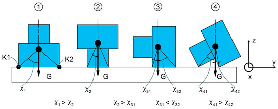
Figure 10.
Preferred orientation of a workpiece [35].
Since the real gripping situation is described in three dimensions, assumptions have to be made for the 2D evaluation of the tilt angle. Here, the supporting surface is described by the x–y plane. The tilt angle must therefore be evaluated two-dimensionally with respect to the yz-plane, which corresponds to a rotation about the last remaining degree of freedom of the x-axis.
After determining the tilt angles (Figure 11a), the surfaces that cannot be considered support surfaces due to the interfering contour of the workpiece are sorted out and marked in red in Figure 11b. For example, the workpiece in Figure 11 cannot be placed on the long side faces because of the surrounding edge, even though they have a large tilt angle. Instead, the support surface marked in green is identified as the preferred orientation and the workpiece is rotated accordingly (Figure 11c). The red surfaces are orthogonal to the gripping axis, but have either a smaller tilt angle or an invalid interference contour.
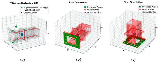
Figure 11.
(a) Tilt angle evaluation of an object; (b) Starting orientation of an object; (c) Reoriented object.
4.3. Generate Finger Configurations
In order to generate a gripper finger configuration from the modular elements at all, the configuration problem must first be described.
4.3.1. Combinatorial Diversity
For the development of a configuration logic, the combinatorial scope of the problem, i.e., the diversity of all possible configurations, is relevant. Based on the previously described modular scope and the configuration problem, and considering the structural design of the gripper fingers, the combinatorial diversity can be derived. The structural setup of each finger always starts with the base module (A) and ends with a fingertip (D). The type of fingertip is determined by the user, depends on the grasping application, and is therefore not a free parameter of a configuration. Assuming that the gripping fingers are symmetrical, only one finger determines the variety of all possible module combinations. The modular scope is therefore halved. The base module and fingertip therefore do not contribute to increasing the number of variants. Building a configuration is like using modules from a construction kit with nine modules () without putting them back, considering the sequence (Formula (1)).
The number of possible combinations therefore increases with the number of modules integrated in a finger (The in Formula (1) stands for the number of draws). In each case, nine modules from the modular system can be freely combined. Since some modules are available several times, the strict consideration of the sequence is relaxed and redundant configurations are removed. For the special case of permutation = 11, 362,880 combinations are possible. After eliminating redundant combinations and considering variable numbers of modules, the scope of the combinatorial task can be specified to 253,534 different configurations.
4.3.2. Kinematic Description
The design of a gripper finger consists of modules that are assembled in a defined sequence. However, the modular structure results in a high degree of shape variation. A set of rules is therefore necessary that determines the shape of the gripper finger on the basis of a module sequence. The kinematic chain of a finger takes place via the connection of the modules at the interfaces. The input interfaces of the modules represent the female part of the quick-change jaw system. The output interfaces are described via pins, which represent the male part of the quick-change jaw system (Figure 12a). In addition to the outer contour of the modules, the type, position, and orientation of the interfaces are also important for the finger shape. To describe the relationships, the module base coordinate system is introduced under the following conventions (Figure 12b):
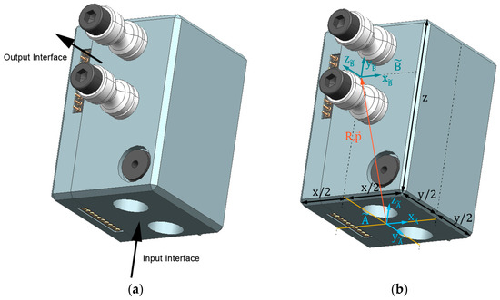
Figure 12.
(a) Module C_1 with input and output interface; (b) Kinematic module description (module C_1).
- The origin is at the center of the module cross-section of the input interface.
- The x-axis points from the electronics connector to the mounting studs.
- The z-axis points in the direction of the mounting hole.
- The y-axis results from the orthonormal base system.
- The position of the output interface is described by the position vector . The orientation corresponds to the rotation matrix . This results in the coordinate system , which restricts the three translational degrees of freedom , , and the three rotational degrees of freedom , , of the module bodies during assembly. The position of the modules relative to each other is thus unambiguously defined. The introduction of this kinematic module description is illustrated in Figure 12. For straight modules, the orientation of the input coordinate system corresponds to that of the output coordinate system . However, for the angled modules and the fingertip, the orientation of the interface changes. In this case, the rotation matrix is obtained by a sequence of elementary rotations about the spatial axes , , . The elementary rotations are introduced as follows:
For the module “C_2” shown in Figure 12, the change in the orientation of the reference system with respect to the reference system is described by a rotation of +90° around the x-axis. The corresponding rotation matrix results in:
The position vector is fixed by design and is with respect to the reference system :
4.3.3. Formulation of the Kinematic Chain
By modeling the individual modules, gripper fingers can be described by serially linking individual modules. A reference coordinate system is required for the comparison and evaluation of different configurations. The gripper coordinate system is introduced according to the conventions of established gripper manufacturers (see Figure 13).
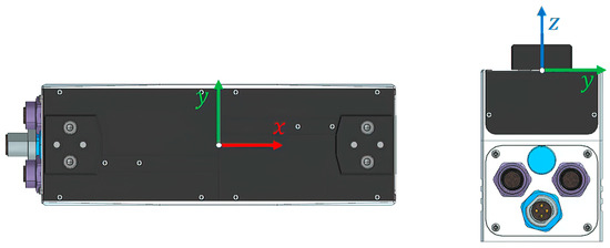
Figure 13.
Gripper coordinate system .
The x-axis designates the gripper axis on which the base jaws of the gripper can be moved in translation. The permissible translation is limited to a maximum jaw stroke, so that only certain gripping widths are possible. The y-axis is also located in the base plane of the gripper and is orthogonal to the x-axis. Lateral projections are therefore described via their y-coordinate. The z-axis is orthogonal to the other two axes and thus points upwards. The length of a gripper finger is described via this direction. When assembling the gripper finger, the next module is always mounted on the previous one. The corresponding orientation of the module is obtained by multiplying the rotation matrices of the previous modules. For the th module, the rotation matrix is obtained according to the rules of forward kinematics [36]:
The assembly position of the th module in gripper coordinates is obtained recursively from the existing kinematic chain. In more detail, the transformation rule concretized in Formula (8) applies according to [37]:
where
- translation of the input interface of the kth module in the gripper coordinate system
- translation of the input interface of the previous module in the gripper coordinate system
- position of the output interface of the previous module in the module coordinate system
The outer contour of the modules can be considered abstractedly as cuboids, which has several advantages: On the one hand, the contour of the gripper finger is described exactly with the help of a few data points. Working with these abstract solids thus keeps the necessary memory requirements low. In addition, the computing time for data processing is reduced compared to a more detailed module description using STL files. For the detailed representation of the gripper fingers envisaged in the following, the STL files of the modules can be transformed via the specification in Formula (8) and thus placed appropriately. This enables visual validation against the real modules and provides valuable assembly information, since details such as the assembly bolts are visible. On the other hand, the data points can be interpreted directly. For example, the output interface of the last module describes the location of the intended gripper contact. A gripper finger can thus be easily analyzed for function fulfillment.
4.3.4. Creating Finger Configurations
With the help of the previously estimated combinatorial diversity as well as the structure of the kinematic chain, finger configurations can be formed. Figure 14 shows some finger configurations as examples.
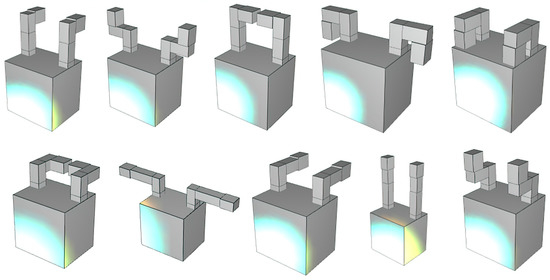
Figure 14.
Generated gripper finger configurations.
Not all of the configurations shown are permissible. For example, in some configurations the fingers collide with each other, or the active surfaces of the fingertips do not point inwards in the direction of gripping. Criteria must therefore be defined to filter out inadmissible configurations.
4.4. Validation of the Configurations
The kinematic chain enables the gripper finger shape to be described. In the next step, the generated configurations must be checked for validity. For this purpose, a distinction is made between object-independent and object-dependent constraints. The object-independent constraints include collision spaces, restrictions on the finger length, and restrictions on the orientation and position of the fingertip. The object-dependent constraints include the permissible object width and collisions.
4.4.1. Object-Independent Validity Check Criteria
In a valid configuration, there must be no overlap between the gripper fingers or between the gripper fingers and the gripper base body. Both the gripper and each module can be abstracted as a cuboid and described as a solid. This results in the tuple for the envelope of the th module. Formula (9) describes the intersection of a mass point with a solid and thus a collision.
where
A collision of the fingers with the gripper base can also be described by the above Formula (9). In addition, it is true that finger modules must not be below the base plane of the gripper (i.e., ). When gripper fingers overlap, collisions between the modules of one finger (Figure 15a), between the two fingers (Figure 15b), and collisions due to the base jaw movement (Figure 15c) are possible. Both fingers collide as soon as they extend into the operating range of the other finger. If the yz-gripper center plane is exceeded, then the fingers come into contact due to the symmetrical boundary condition. Finger pairings that already touch each other in the fully extended state () cannot be mounted and must therefore be declared invalid. A pair of fingers blocks if the gripping space, which is spanned by the fingertips, is occupied by other modules.
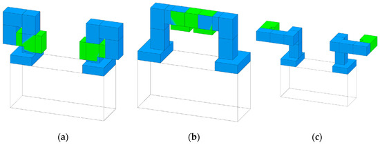
Figure 15.
(a) Collision of fingers with itself; (b) Collision of the two fingers with each other; (c) Collision of the fingers when moving the jaws.
The gripping forces and the weight forces and inertias of the moving handling objects result in a tilting moment with the components , and , which acts on the base jaws of the gripper. The tilting moment increases with increasing length of the lever arms of the acting forces. Due to durability and dimensioning aspects, the permissible lever arms are therefore limited.
The finger length is defined by the z-coordinate of the fingertip. In the load-free state, it has no influence on the applied tilting moment. When the workpiece is grasped, contact forces occur that correspond in magnitude to the gripping forces. These forces act in the direction of the gripping axis. In combination with a y-projection, the components and are thus imposed. To limit the tilting moment, restrictions on the finger length Z and the projection Y are therefore formulated by the gripper manufacturer (Formula (10)). The limiting curves result analytically as a second-order polynomial. By rearranging the polynomial, the boundary condition in Formula (11) follows. Using the parameters a and b, the boundary condition can be defined variably for different grippers.
Configurations occur in which, in addition to the lateral projection Y, a projection X occurs in the direction of movement. The grasp width can be variably adjusted via the projection X. With increasing projection X, the wear of the gripper increases, since increased compliance of the fingers promotes longer sliding paths of the jaw guide.
The curve shown in Figure 16 for the two gripper types SCHUNK EGL 90 and SCHUNK EGI 80, which limit the lever arms of the forces, serve as the basis for the calculation. The combination of the X and Y projections is also interpreted as a lever arm and thus defined as a geometric length. The two-dimensional criterion is extended accordingly (Formula (12)).
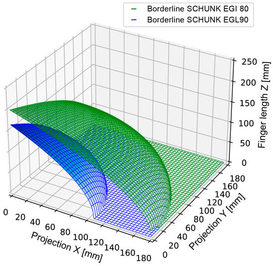
Figure 16.
Three-dimensional restriction on finger length and projection.
As a result of a variable module sequence, configurations arise in which the effective surfaces of the fingertips are not opposite to each other. If, in addition, the normal vector of a fingertip does not point in the direction of the gripping axis, then no valid grasp is produced when the jaws are closed. The kinematic description of inner and outer grasps here places requirements on the direction of the fingertips, which is defined by the normal vector . All other orientations of the fingertips are invalid. Due to the module size, only internal grasps for comparatively large grasp widths can be realized. For this reason, only external grasps are considered in the following.
In addition, the mounting direction of the fingertip must not point in the negative z-direction, as collision-free gripping is usually not possible when taking the deployment situation into account due to the interfering contour of the finger.
4.4.2. Object-Dependent Validity Check Criteria
The demand for a high degree of automation and easy operability of the configuration algorithm requires robust processing of variable user data. The workpieces are provided by the user in the form of STL files. This data format uses triangular facets to model the geometric shape of the workpieces to be grasped. The STL files are made up of vertices, which form a mesh via triangulation. The coordinates of the vertices always refer to a fixed reference coordinate system, which is called the object coordinate system in the following. The object coordinate system usually originates from the constructive structure of the handling object in a CAD program. When the design is derived as an STL file, this coordinate system is adopted. The coordinate system is therefore unrelated to the gripping task and the gripper coordinate system.
To examine the workpieces, they must be described in gripper coordinates and thus first transformed. The grasp point determination described above determines the gripping points and normal vectors of the gripping surfaces with respect to the object coordinate system. To determine the transformation rule, which transforms the coordinate systems into each other (Formula (8)), the rotation matrix and the translation vector must be determined. The following assumptions are formulated:
- The normal vectors of the gripping surfaces must point in the direction of the gripping axis to produce a valid grip.
- The gripping points must touch the fingertip at their center to ensure maximum gripping reliability.
The first assumption here places a requirement on the orientation of the workpiece, which is rotated by angle about the axis of rotation in target pose. The rotation axis (Formula (13)) and the rotation angle (Formula (14)) can be derived according to [38].
where is the rotation axis, is the start vector and is the target vector. The angle of rotation is given by
With this, the Euler parameters , , , can be determined with which the rotation matrix can then be built up (Formula (15)).
The second assumption defines the translation of the workpiece, which depends on the finger geometry. The workpiece is first translated to the origin so that the y- and z-coordinates of the gripping points are zero. Then, the workpiece is moved in the x-direction so that the center of the line connecting the two gripping points is at the origin of the gripper coordinate system. In combination with symmetrical gripper fingers, simultaneous gripping is thus ensured.
In addition to collisions of the fingers with each other or with the gripper, collisions can also occur if the fingers collide with the object before the gripping position is reached, for example. Other approaches use the collision detection available in CAD programs for this purpose [39]. Unlike in [39], in the automated configuration of modular fingers, the absence of collisions is a prerequisite for the validity of a finger pair and is not used to check a single finger configuration at the end of the design process. For this, an efficient procedure with a short runtime is required.
For an efficient collision detection, a precise, as well as efficiently structured representation of the 3D objects is necessary. To reduce the number of necessary overlap tests, both fingers and workpieces can be represented by hierarchically nested bounding volumes. The bounding volumes completely enclose an object and thus allow the overlap tests to be performed for simple geometries. Oriented Bounding Boxes (OBBs) are aligned with the axes of the object. The oriented cuboids provide a very good envelope efficiency, i.e., the object can be described sufficiently accurately with little effort. On the other hand, the OBB model does not require recalculation during rotation, since the cuboids are already created to be rotationally symmetrical during their initial calculation, and the collision detection works independently of the resolution of the STL files in terms of reliability [40]. By exploiting these two properties, an enormous gain in runtime can be achieved. Due to the hierarchical structure in so-called OBBTrees, the accuracy of the approximation and thus the number of intersection tests to be performed is adjusted depending on the distance between two collision objects. Only if an intersection test of the outermost enveloping cube is positive are finer discretization and further intersection tests performed. During collision detection, the gripping process is traced and the gripper fingers are moved towards the workpiece. A finger configuration is invalid if a collision is detected before the gripping point is reached. The entire gripping process is tracked, so that not only collisions in the gripping position, but also during the approach of the base jaws are detected.
Considering the object-dependent and -independent constraints, the determined gripper finger configurations can be filtered and inadmissible configurations can be excluded.
Figure 17 shows the result of a configuration for a sphere. To distinguish the gripper, the configuration, the fingertip, and the workpiece, these are each shown in different colors (blue, gray, red, and orange). During the configuration process, the modules are modeled only by their outer contour for computational efficiency and shape interpretability. For the output of the configuration result, STL files of the real modules are integrated into the visualization. Details such as the locking bolt and the mounting orientation of the universal base plate are visible. Thus, important information about the assembly process can be provided to the user. For better orientation and clarity of the display, the gripper coordinate system and an orientation cube are visually integrated. The module sequence for the right and left fingers can be read directly.
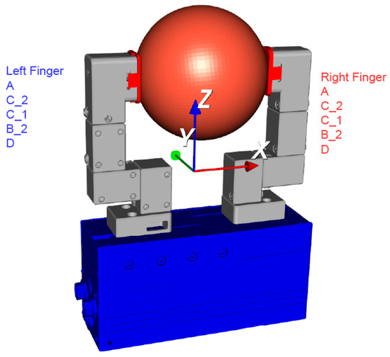
Figure 17.
Representation of a configuration (workpiece Spherical 6).
4.5. Evaluation of the Gripper Finger Configurations
After filtering the gripper finger configurations, a list of valid configurations is available. However, not all valid configurations solve the gripping task with the same quality. Therefore, a decision logic is required that compares the gripper finger configurations for a workpiece with each other, evaluates them, and then determines the best configuration for a workpiece. The resulting optimization problem has as its objective function the maximization of the quality of the gripper fingers under the condition that all handling objects must be gripped.
The solution to the optimization problem is a utility value that describes the achievable finger quality with a configuration.
Criteria for Evaluating a Finger Configuration
The assembly of a gripper finger from modules of a modular system leads to new requirements for the evaluation of a gripper finger, which have not been considered in the literature so far. Therefore, a separate approach for the evaluation of finger configurations is derived. The quality of a finger configuration results from the evaluation of different criteria. The following six independent criteria are introduced in which the influencing factors are summarized that are related to the finger configuration:
- Finger length
- Number of modules
- Projection
- Cycle time
- Flexibility
The criteria are briefly described below.
While gripper fingers that are too short are not permissible for collision reasons, the quality of a configuration decreases if the finger length is too long. This is due to increased stress on the components, since the tilting moment, which is impressed on the base jaws, increases with increasing finger length. In addition, a long finger length increases the bending up of the fingers, so that the working surfaces at the fingertips are no longer suitably aligned with the workpiece. The deviation of the finger length (z-position of the fingertip) from the ideal finger length (workpiece-specific) is used to evaluate the finger length.
The assembly of modules to form a gripper finger is synonymous with the creation of a tolerance chain. Particularly in the case of fingers that are individually adapted to the workpiece, there are high requirements for precise module dimensions so that no change occurs in the tool center point (TCP) when the finger is changed [41]. A high number of modules has a negative effect on the accuracy of the finger. As a result of multiple, tolerance-affected modules, the position of the fingertip scatters. The number of modules on a gripper finger is used to evaluate this criterion.
The position of the grasp point in the gripper coordinate system, in combination with the workpiece weight, determines the acting tilting moment on the base jaw. The criterion of the finger length already considers the tilting moment in the y-direction. A tilting moment about the z-axis occurs as a result of non-centered grips with projected fingers. This eccentricity is object-dependent if the virtual axis connecting the gripping points does not pass through the object’s center of gravity. The y-position of the fingertip is used to evaluate this criterion.
The time required to establish a valid grip increases proportionally with the required travel distance of the base jaws. The jaw stroke must therefore also be minimized to achieve short cycle times. This also supports the requirement for a low envelope of the gripper with its fingers, since short jaw strokes are accompanied by a minimization of projections in the direction of the gripper axis. The necessary jaw stroke with a configuration is used to evaluate the cycle time.
The flexibility of a gripper finger describes its ability to handle multiple workpieces without the need to change fingers [42]. A flexible finger thus reduces investment costs and saves time in setting up the handling application. The percentage of workpieces in a data set that can be gripped with a configuration is used to evaluate flexibility. To determine the degree of fulfillment of a configuration, a utility value is introduced, which is the result of the value for each criterion plus a weighting factor. The weighting is determined via a pairwise comparison between the criteria. The finger length, flexibility, and cantilever represent the most important criteria. Since only minor time savings can be expected as a result of a reduced jaw stroke, this criterion—together with the number of modules—is considered to be of the least importance. To determine the degree of fulfillment of the criteria, the range of values is divided linearly into five levels.
Figure 18 shows the result of a configuration for a sphere. To distinguish the gripper, the configuration, the fingertip, and the workpiece, these are each shown in different colors (blue, gray, red, and orange). During the configuration process, the modules are modeled only by their outer contour for computational efficiency and shape interpretability. For the output of the configuration result, STL files of the real modules are integrated into the visualization. Details such as the locking bolt and the mounting orientation of the universal base plate are visible. Thus, important information about the assembly process can be provided to the user. For better orientation and clarity of the display, the gripper coordinate system and an orientation cube are visually integrated. The module sequence for the right and left fingers can be read directly. This makes it possible to determine a list of evaluated configurations for almost any object and display it for the user.
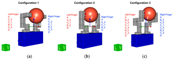
Figure 18.
Extract from the configuration results.
An excerpt of the configuration results for the sphere shown earlier is shown in Figure 18. Three configurations are listed here as an example. The corresponding evaluation can be taken from Table 1. In configuration 1 in Figure 18a, each finger consists of six modules and has projections in the gripping direction and perpendicular. Configuration 2 in Figure 18b consists of five modules each and with a projection only in the gripping direction to achieve the necessary opening width. In configuration 3 (Figure 18c), each finger consists of eight modules. In addition, there are projections in the gripping direction and perpendicular. As the number of modules increases, the torque on the base jaws of the gripper increases and the gripping force decreases. With increasing projection, the load on the base jaw increases and thus also does the wear of the gripper. This is reflected in the evaluation in Table 1: Configurations 1 and 3 achieve a lower overall utility than configuration 2 due to the larger projection and the larger number of modules.

Table 1.
Exemplary result of the utility analysis.
The following figures show the best rated configurations for workpieces from the workpiece spectrum in each case.
The time required to determine the best configuration in each case depends on the complexity of the handling objects. Therefore, the times for determining the gripping points and the configurations for the part shown in Figure 19 are listed in the following table.
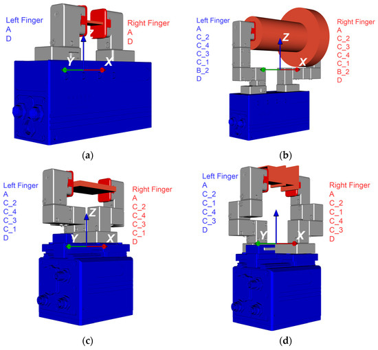
Figure 19.
Finger configuration for (a) Flat part 1 (Gripper SCHUNK EGI 80); (b) Mushroom part 5 (Gripper SCHUNK EGI 80); (c) Flat part 3 (Gripper SCHUNK EGL 90); (d) Schmalz part 2 (Gripper SCHUNK EGL 90).
Table 2 shows that in less than a minute, gripping points can be determined and evaluated, and gripper finger configurations can be determined, evaluated, and visualized.
Table 2.
Number of configurations and overview of lead times 1.
5. Conclusions and Future Work
In order to simplify the problem of the time-consuming and complex design of application-oriented gripper fingers for industrial applications, this paper presents a method that enables the automated design of gripper fingers from a modular construction kit. Based on an already presented, methodically developed, modular gripper finger construction kit, as well as a set of workpieces, an analytical gripper position determination is realized, which is the basis for the determination of gripper finger configurations. The gripper fingers are selected in such a way that they are distributed as widely as possible over the workpiece, taking the grip quality into account. With the help of a kinematic description of the modules, finger configurations can then be built up in the form of kinematic chains. The configurations thus determined are then tested and evaluated for validity so that the best configuration can be determined for each workpiece.
This work provides an alternative approach to automated gripper finger design for grippers in industrial robotics applications. Unlike existing approaches, modules are assembled from predefined modules. This can shorten the readiness time for new fingers, since the new finger designs do not have to be manufactured. In addition, standard components (the modular elements) can be used, allowing economies of scale to be exploited and increasing the reliability of the individual elements. The research results show that it is possible to realize gripper fingers for a large number of different objects with a small number of different modules. In the context of an increasing number of variants and small quantities, gripper fingers can thus be quickly adapted to new handling tasks.
The approach thus supports current developments in the field of automated gripper finger design, which are aimed at the rapid adaptation of grippers by using simulations [43], thus avoiding time-consuming design iterations, or by the automated design [31] and replacement [24] of only a few components. So far, the approach has been applied and verified with two grippers and the defined workpiece spectrum. The transferability to further grippers is planned, e.g., by the outsourced description of the grippers and modules, but not yet tested. The construction kit used has been developed methodically, but must be checked again, especially in the context of configuration.
A comparison to existing approaches regarding finger quality, deployment times, costs, or mechanical properties of the fingers is difficult due to missing information. However, some statements can be made:
- The individualization of the gripper fingers determined here is limited in contrast to existing approaches for individual gripper fingers (e.g., [3] or [21]).
- Regarding the finger quality, the evaluation of the fingers is described above and can be used for comparability in other approaches. Except for the number of modules, the criteria can also be used for other types of gripper fingers.
- The times required to determine the configurations shown in Figure 19 can be taken from Table 2. In addition, there is the assembly effort required to assemble the fingers. The lead time for gripper fingers that are designed manually, according to the Generic Automated Finger Design [21], or with eGrip [3] is at least 16 min for a bottle cap [30]. The time required for printing the fingers is unknown. This results in significant time saving for the automated design of manual gripper fingers.
- The mechanical properties are considered in the conception of the modular system as well as in the design of the modules. Due to the interfaces between modules, this results in a larger bending up during grasping than in monolithic fingers. However, the fingers used in [5] or in [21] are made of plastic. Therefore, comparatively good mechanical properties can be assumed for modular gripper fingers.
- With regard to cost, an assessment becomes difficult because sensor integration is provided in the modular gripper fingers, which increases the cost of the fingers, is not provided in other approaches, and their benefit assessment is subjective.
To improve the approach described here, the throughput of an automated handling solution with modular gripper fingers shall be increased. For this purpose, the minimum number of different configurations required for a set of handling objects will be investigated. An MTM analysis (method-time measurement) will be used to determine how much manual effort is required to remove, add, or replace modules. Based on the determined times, the setup effort can then be defined as a further criterion. This increases with the number of manual setup operations between the workpieces. For example, if it is possible to handle five workpieces with only two configurations, then the setup effort decreases. A trade-off is therefore necessary between the quality of the configuration and the setup effort. To increase the individualization of the fingers, the automated design of the die surface could be integrated in the future. The interchangeability of the die surface, which was already taken into account in the design of the modular construction kit, could thus be individually adapted to workpieces in a short time. For the comparability of manufacturing costs, a bottom-up calculation could be performed. The added value of the sensor integration would also have to be evaluated in this process.
Author Contributions
Conceptualization, M.F., C.F. (Christian Friedrich) and J.F.; methodology, M.F., D.K. and J.H.; software, D.K., M.L., J.H., C.F. (Christian Frech) and G.L.; validation, D.K., C.F. and J.H.; formal analysis, M.F.; investigation, M.F., D.K., J.H., M.L. and C.F. (Christian Frech); resources, M.F.; data curation, M.F. and D.K.; writing—original draft preparation, M.F.; writing—review and editing, M.F., D.K., C.F. (Christian Frech), M.L., G.L., J.H., C.F. (Christian Friedrich) and J.F.; visualization, M.F., D.K. and J.H.; supervision, J.F.; project administration, M.F. All authors have read and agreed to the published version of the manuscript.
Funding
This research received no external funding.
Data Availability Statement
Not applicable.
Conflicts of Interest
The authors declare no conflict of interest.
References
- Causey, G.C.; Quinn, R.D. Gripper design guidelines for modular manufacturing. In Proceedings of the 1998 IEEE International Conference on Robotics and Automation, Leuven, Belgium, 16–20 May 1998; Cat. No.98CH36146. pp. 1453–1458, ISBN 0-7803-4300-X. [Google Scholar]
- Honarpardaz, M.; Meier, M.; Haschke, R. Fast grasp tool design: From force to form closure. In Proceedings of the 2017 13th IEEE Conference on Automation Science and Engineering (CASE), Xi’an, China, 20–23 August 2017; pp. 782–788, ISBN 978-1-5090-6781-7. [Google Scholar]
- Nagel, M.; Giese, F.; Becker, R. Flexible Gripper Design through Additive Manufacturing. In Robotic Fabrication in Architecture, Art and Design 2016; Reinhardt, D., Saunders, R., Burry, J., Eds.; Springer International Publishing: Cham, Switzerland, 2016; pp. 455–459. ISBN 978-3-319-26376-2. [Google Scholar]
- Birglen, L.; Schlicht, T. A statistical review of industrial robotic grippers. Robot. Comput. Manuf. 2018, 49, 88–97. [Google Scholar] [CrossRef]
- Schmalz, J. Rechnergestützte Auslegung und Auswahl von Greifersystemen. Ph.D. Thesis, Technische Universität München, München, Switzerland, 2018. [Google Scholar]
- Pott, A.; Dietz, T. Industrielle Robotersysteme: Entscheiderwissen für die Planung und Umsetzung wirtschaftlicher Roboterlösungen; Springer Vieweg: Wiesbaden, Germany, 2019; ISBN 978-3-658-25345-5. [Google Scholar]
- Velasco, V. A Methodology for Computer-Assisted Gripper Customization Using Rapid Prototyping Technology. Ph.D. Thesis, Case Western Reserve University, Cleveland, OH, USA, 1997. [Google Scholar]
- Brown, R.; Brost, R. A 3-D modular gripper design tool. IEEE Trans. Robot. Autom. 1999, 15, 174–186. [Google Scholar] [CrossRef]
- Wallack, A.S.; Canny, J.F. Planning for Modular and Hybrid Fixtures. Algorithmica 1997, 19, 40–60. [Google Scholar] [CrossRef]
- PHD Inc. Modular Gripper Jaw Tooling: CLICK & GRIP. Available online: https://www.phdinc.com/pdf/CLICK-GRIP.pdf (accessed on 9 August 2021).
- Li, C.; Gu, X.; Ren, H. A Cable-Driven Flexible Robotic Grasper with Lego-Like Modular and Reconfigurable Joints. IEEE/ASME Trans. Mechatron. 2017, 22, 2757–2767. [Google Scholar] [CrossRef]
- Wolniakowski, A.; Miatliuk, K.; Krüger, N.; Rytz, J.A. Automatic Evaluation of Task-Focused Parallel Jaw Gripper Design. In Proceedings of the Simulation, Modeling, and Programming for Autonomous Robots: 4th International Conference, SIMPAR 2014, Bergamo, Italy, 20–23 October 2014. [Google Scholar] [CrossRef]
- Brandenburg, A.; Smolka, G.; Dilthey, U. Assembly of hybrid micro-systems? The SFB 440. Microsyst. Technol. 2004, 10, 247–251. [Google Scholar] [CrossRef]
- Pham, D.T.; Gourashi, N.S.; Eldukhri, E. Automated configuration of gripper systems for assembly tasks. Proc. Inst. Mech. Eng. Part B J. Eng. Manuf. 2007, 221, 1643–1649. [Google Scholar] [CrossRef]
- Tzafestas, S. Integrated sensor-based intelligent robot system. IEEE Control Syst. Mag. 1988, 8, 61–72. [Google Scholar] [CrossRef]
- Kakogawa, A.; Nishimura, H.; Ma, S. Underactuated modular finger with pull-in mechanism for a robotic gripper. In Proceedings of the 2016 IEEE International Conference on Robotics and Biomimetics (ROBIO), Qingdao, China, 3–7 December 2016; pp. 556–561. [Google Scholar] [CrossRef]
- Salisbury, C.M.; Quigley, M. Robotic Hand with Modular Extensions. U.S. Patent US13951347, 25 July 2013. [Google Scholar]
- Weiss, K.; Woern, H. Development of a modular anthropomorphic robot hand using servohydraulic actuators. In Proceedings of the 2004 4th IEEE/RAS International Conference on Humanoid Robots, Santa Monica, CA, USA, 10–12 November 2004; pp. 64–76, ISBN 0-7803-8863-1. [Google Scholar]
- Weiss Robotics GmbH & Co. KG. GRiPKIT by Weiss Robotics: Smarte Greiflösungen für Cobots. Available online: https://www.google.com/url?sa=t&rct=j&q=&esrc=s&source=web&cd=&cad=rja&uact=8&ved=2ahUKEwjDl9C0ndn1AhXL2KQKHf1pBnkQFnoECAQQAQ&url=https%3A%2F%2Fweiss-robotics.com%2Fproducts%2Fsystem-solutions%2Fgripkit%2Fgrip-kit-cr%2Fgripkit-cr-plus%2Fproduct%2Fgripkit-cr-plus%2F%3Ffile%3Dfiles%2Fmerconisfiles%2Fthemes%2Ftheme8%2Fdownloads%2Fgripkit%2FQ3-2019_GRIPKIT_de_en.pdf%26cid%3D9995&usg=AOvVaw3is5hiNIjVgtUGQK6q2Wrf (accessed on 30 January 2022).
- Weiss Robotics GmbH & Co. KG. FiNGERKIT by Weiss Robotics. Available online: https://weiss-robotics.com/fingerkit/ (accessed on 5 August 2021).
- Honarpardaz, M. Finger Design Automation for Industrial Robots: A Generic and Agile Approach; Linköping University Electronic Press: Linköping, Sweden, 2018; ISBN 9789176853436. [Google Scholar]
- Whitesides, G.M. Soft-Robotik. Angew. Chem. 2018, 130, 4336–4353. [Google Scholar] [CrossRef]
- Shintake, J.; Cacucciolo, V.; Floreano, D.; Shea, H. Soft Robotic Grippers. Adv. Mater. 2018, 30, 1707035. [Google Scholar] [CrossRef] [PubMed]
- Wolniakowski, A.; Lindvig, A.; Iversen, N.; Krüger, N.; Kramberger, A. Robotic Finger Design Workflow for Adaptable Industrial Assembly Tasks. In Proceedings of the International Conference on Robotics, Computer Vision and Intelligent Systems, Budapest, Hungary, 4–6 November 2020. [Google Scholar] [CrossRef]
- Morales, A. From Robot to Human Grasping Simulation, 1st ed.; Springer International Publishing AG: Cham, Switzerland, 2014; ISBN 978-3-319-01833-1. [Google Scholar]
- Ferrari, C.; Canny, J. Planning optimal grasps. In Proceedings of the 1992 IEEE International Conference on Robotics and Automation, Nice, France, 12–14 May 1992; pp. 2290–2295, ISBN 0-8186-2720-4. [Google Scholar]
- Brost, R.C.; Peters, R.R. Automatic design of 3-d fixtures and assembly pallets. In Proceedings of the IEEE International Conference on Robotics and Automation, Minneapolis, MN, USA, 22–28 April 1996; pp. 495–502, ISBN 0-7803-2988-0. [Google Scholar]
- Pedrazzoli, P.; Rinaldi, R.; Bobertoer, C.R. A rule based approach to the gripper selection issue for the assembly process. In Proceedings of the 2001 IEEE International Symposium on Assembly and Task Planning (ISATP2001), Assembly and Disassembly in the Twenty-first Century, Fukuoka, Japan, 28–29 May 2001; Cat. No.01TH8560. pp. 202–207, ISBN 0-7803-7004-X. [Google Scholar]
- Sanfilippo, F.; Salvietti, G.; Zhang, H.Z.; Hildre, H.P.; Prattichizzo, D. Efficient modular grasping: An iterative approach. In Proceedings of the 2012 4th IEEE RAS & EMBS International Conference on Biomedical Robotics and Biomechatronics (BioRob), Rome, Italy, 24–27 June 2012; pp. 1281–1286, ISBN 978-1-4577-1200-5. [Google Scholar]
- Honarpardaz, M.; Tarkian, M.; Ölvander, J.; Feng, X. Experimental verification of design automation methods for robotic finger. Robot. Auton. Syst. 2017, 94, 89–101. [Google Scholar] [CrossRef]
- Ringwald, J.; Schneider, S.; Chen, L.; Knobbe, D.; Johannsmeier, L.; Swikir, A.; Haddadin, S. Towards Task-Specific Modular Gripper Fingers: Automatic Production of Fingertip Mechanics. IEEE Robot. Autom. Lett. 2023, 8, 1866–1873. [Google Scholar] [CrossRef]
- Friedmann, M.; Schabel, S.; Gerber, J.; Döhring, A.; Meschter, L.; Fleischer, J.; May, M. Greiferfinger für eine schnelle Rekonfiguration/Gripper fingers for fast reconfiguration—Modular construction kit for creating application-specific gripper fingers. wt Werkstattstech. Online 2022, 112, 629–634. [Google Scholar] [CrossRef]
- Wolf, A.; Schunk, H. Grippers in Motion; Hanser: Munich, Germany, 2018; ISBN 978-1-56990-714-6. [Google Scholar]
- DIN Deutsches Institut für Normung e.V. Normzahlen und Normzahlreihen: Hauptwerte Genauwerte Rundwerte; Beuth Verlag: Berlin, Germany, 1974; 17.020 (DIN 323 Blatt 1); Available online: https://www.beuth.de/de/norm/din-323-1/683378 (accessed on 3 June 2023).
- Hesse, S. Grundlagen der Handhabungstechnik; 5. Neu Bearbeitete Auflage; Hanser: München, Germany, 2020; ISBN 978-3-446-46359-2. [Google Scholar]
- Siciliano, B.; Khatib, O. Springer Handbook of Robotics, 2nd ed.; Springer: Berlin/Heidelberg, Germany, 2016; ISBN 978-3-319-32550-7. [Google Scholar]
- Pfeiffer, F.; Schindler, T. Einführung in die Dynamik; 3. Auflage; Springer Vieweg: Berlin/Heidelberg, Germany, 2014; ISBN 978-3-642-41046-8. [Google Scholar]
- Rill, G.; Schaeffer, T.; Borchsenius, F. Grundlagen und computergerechte Methodik der Mehrkörpersimulation: Vertieft in Matlab-Beispielen, Übungen und Anwendungen; 4. Auflage; Springer Vieweg: Wiesbaden/Heidelberg, Germany, 2020; ISBN 978-3-658-28912-6. [Google Scholar]
- Honarpardaz, M.; Ölvander, J.; Tarkian, M. Fast finger design automation for industrial robots. Robot. Auton. Syst. 2019, 113, 120–131. [Google Scholar] [CrossRef]
- Gottschalk, S.; Lin, M.C.; Manocha, D. OBBTree. In SIGGRAPH96: 23rd International Conference on Computer Graphics and Interactive Techniques; Fujii, J., Ed.; ACM: New York, NY, USA, 1996; pp. 171–180. ISBN 0897917464. [Google Scholar]
- Hesse, S. Greiftechnik: Effektoren für Roboter und Automaten; Carl Hanser Verlag: München, Germany, 2011; ISBN 978-3-446-42422-7. [Google Scholar]
- Monkman, G.J. Robot Grippers; Wiley-VCH: Weinheim, Germany, 2007; ISBN 978-3-527-40619-7. [Google Scholar]
- Ramasubramanian, A.K.; Connolly, M.; Mathew, R.; Papakostas, N. Automatic simulation-based design and validation of robotic gripper fingers. CIRP Ann. 2022, 71, 137–140. [Google Scholar] [CrossRef]
Disclaimer/Publisher’s Note: The statements, opinions and data contained in all publications are solely those of the individual author(s) and contributor(s) and not of MDPI and/or the editor(s). MDPI and/or the editor(s) disclaim responsibility for any injury to people or property resulting from any ideas, methods, instructions or products referred to in the content. |
© 2023 by the authors. Licensee MDPI, Basel, Switzerland. This article is an open access article distributed under the terms and conditions of the Creative Commons Attribution (CC BY) license (https://creativecommons.org/licenses/by/4.0/).