Abstract
This paper presents a detailed design of a skid-steering mobile platform with four wheels, along with a Cartesian serial (PPP) manipulator. The aim of this design is to enable the platform to perform various tasks in the agricultural process. The parallel manipulator designed can handle heavy materials in the agricultural field. An experimental robotic harvesting scenario was conducted using parallel manipulator-based end-effectors to handle heavy fruits such as watermelon or muskmelon. The conceptual and component design of the different models was carried out using the Solidworks modeling package. Design specifications and parametric values were utilized during the manufacturing stage. The mobile manipulator was simulated on undulating terrain profiles using ADAMS software. The simulation was analyzed for a duration of 15 s, and graphs depicting the distance, velocity, and acceleration were evaluated over time. Proportional derivative control and proportional derivative-like conventional sliding surface control were applied to the model, and the results were analyzed to assess the error in relation to the input and desired variables. Additionally, a structural analysis was performed to ensure minimal deformation and the highest safety factor for the wheel shaft and L bracket thickness. Throughout the fabrication and prototype development, calibration tests were conducted at various X-, Y-, and Z-axis frame mounting stages. The objective was to minimize the lateral and longitudinal deviation between the parallel linear motion (LM) rails. Once the fabrication and prototype construction was completed, field testing was carried out. All mechanical movements in the lateral and longitudinal directions functioned according to the desired commands given by the Arduino Mega, controlled via a six-channel radio frequency (RF) controller. In the context of agriculture, the grippers utilizing parallel mechanisms were also subjected to testing, demonstrating their ability to handle sizable cylindrical and spherical fruits or vegetables, as well as other relevant objects.
1. Introduction
Agriculture is undergoing a rapid transformation, emerging as an appealing high-tech industry that attracts professionals, businesses, and investors alike. This sector’s technological advancements are not only enhancing farmers’ production capacity but also revolutionizing the field of robotics and automation.
Since its inception thousands of years ago, farming has been a groundbreaking concept that allowed our ancestors to settle in one place and lay the foundations for future civilizations. However, as time has progressed, the strain on agriculture has steadily increased. Traditional farming practices are no longer sustainable, unable to keep pace with the growing global population. The pressing challenge lies in meeting the escalating demand for significantly improved production yields. According to the United Nations, the world’s population, currently at 7.3 billion, is projected to reach 9.7 billion by 2050. This population growth will require a substantial increase in food production, placing farmers under immense pressure to meet the rising demand.
Robotic systems have assumed an increasingly significant role in modern agriculture, becoming an integral part of precision agriculture or digital farming [1,2]. These robots operate autonomously, eliminating the need for experienced operators to carry out various farming tasks [3]. This autonomous capability represents a major advantage over traditional tractor-based systems [4,5]. Agricultural robots play a vital role in assisting farmers to achieve higher output yields through various means. This technology finds application in innovative and diverse fields, including drones, self-driving tractors, and robotic arms. By performing slow, repetitive, and mundane tasks, agricultural robots alleviate farmers’ burden, allowing them to concentrate on enhancing overall productivity.
The field of agricultural robotics has witnessed remarkable advancements, paving the way for a multitude of innovative applications [6,7]. Further, autonomous robots have been successfully employed in a wide range of farming operations, such as harvesting [8,9,10,11,12,13,14,15,16,17,18]. The process of harvesting, once considered labor-intensive and time-consuming, has been transformed by the integration of robotics. Harvesting robots are now capable of efficiently and delicately harvesting various crops, ensuring minimal damage and maximizing productivity. These machines also mitigate the dependence on manual labor, addressing the ongoing challenges of labor shortages faced by the agricultural industry. Notable examples of robotic systems that are used in harvesting include asparagus harvesting [19], sweet pepper harvesting [20,21], tomato harvesting [22,23], cucumber harvesting [24], strawberry harvesting [25,26,27], and apple harvesting [28,29,30]. Post-harvesting operations, often critical for preserving the quality and shelf life of harvested crops, have also benefited from robotic innovations [31]. Automated sorting, grading, and packaging systems ensure that the harvested produce is handled with precision and care, reducing waste and enhancing the overall supply chain efficiency.
Crop monitoring, a fundamental aspect of modern agriculture, has been revolutionized by robotics. Through the use of specialized robots equipped with advanced sensors and imaging technology, farmers can now obtain real-time data on their crops’ health, growth, and overall condition. These valuable insights allow for timely interventions and adjustments, optimizing crop yields and ensuring sustainable practices. These cutting-edge technologies have been applied in various crop monitoring [32,33] applications. Weed control, which has long been a labor-intensive and challenging task for farmers, has also seen significant improvements thanks to agricultural robots. These robots are designed to identify and selectively eliminate weeds without harming the desired crops, thereby reducing the reliance on herbicides and promoting more eco-friendly agricultural practices. In this direction, these autonomous robots have been instrumental in pest and weed control, as demonstrated in studies [34,35,36,37,38,39]. Beyond the primary focus areas, robots have found utility in a myriad of agricultural tasks. Soil monitoring robots help assess soil quality, moisture levels, and nutrient content, providing essential data to optimize fertilization and irrigation strategies [40]. Seed planting and seedling manipulation robots guarantee precise and consistent planting, promoting strong and healthy plant growth [41,42]. Furthermore, robots are actively involved in the fertilization process, delivering nutrients in a targeted and efficient manner [43,44,45]. This approach minimizes resource wastage while providing crops with the nourishment they require for robust development. Agricultural robots have also revolutionized irrigation practices. Automated systems efficiently deliver water to crops based on their specific needs, conserving water resources and reducing water wastage [46]. Target spraying is one of the tasks that are executed by automated machines or robotic systems [37,47,48,49,50]. Similarly, pruning operations have also received attention and brought developments in robotic systems [51,52,53] for the same. Conversely, the phenotyping task has garnered significant attention from the robotic community, leading to the development of numerous robotic systems [54,55] aimed at addressing this challenge. Finally, crop protection has become more effective and sustainable through the deployment of robots. They can monitor for pests and diseases, enabling timely interventions and reducing the need for chemical pesticides [56,57].
Overall, these advancements in agricultural robotics have ushered in a new era of efficient and sustainable farming practices. By harnessing the power of technology, farmers can now meet the growing global demand for food while minimizing environmental impacts and ensuring a more resilient agricultural industry for the future. Agricultural robots are currently in the prototype phase, demonstrating their potential to perform various farming operations. Among these applications, harvesting and picking are particularly prevalent in agricultural robotics. Robots excel in precision and speed, enabling them to increase yield size while minimizing crop waste left in the field. Multipurpose autonomous field navigation, harvesting, and picking robots [9,55,58,59,60,61,62,63,64,65,66,67] are gaining popularity among farmers. However, there are numerous other innovative ways in which the agricultural industry is embracing robotic automation to enhance output yields. As the demand for food continues to outstrip available cropland, it is crucial for farmers to bridge this gap. Agricultural robots serve as valuable tools to assist them in this endeavor.
Hence, the availability of a flexible and adaptable vehicle manipulator platform, both in terms of hardware and software, within a research laboratory provides the opportunity to simulate diverse scenarios and explore various solutions from fundamental and practical research perspectives, ultimately advancing the overall field of study. Incorporating sensors, actuators, and other essential equipment allows for experimental replication of key aspects in various applications. These may include generating external forces, enabling interactive interactions, influencing trajectory tracking through weight distribution, facilitating ground vehicle localization, and ensuring secure remote human engagement. Achieving successful integration and deployment of such hardware in precision agriculture necessitates the development of novel algorithms and technical innovations. This research paper presents a versatile vehicle manipulator system designed specifically for agricultural applications, with a focus on harvesting heavy fruits, weed removal, and pruning tasks. The system incorporates customized end-effectors to facilitate these operations effectively.
The paper is organized into several sections. In Section 2, the proposed functional design is described. Section 3 presents the analysis of velocity and force for the mobile base, while Section 4 covers the kinematic analysis of the proposed system. Detailed dynamic modeling and motion control are discussed in Section 5. The hardware implementation and experimental testing results conducted in a laboratory environment with the in-house fabricated prototype are presented in Section 6. Finally, Section 7 provides the main conclusions drawn from the study.
2. Design of the Proposed Agriculture Robot
The agricultural harvesting tasks encompass various types, including bulk harvesting of crops like paddy (rice), wheat, corn, sugarcane, etc. [68,69], as well as selective harvesting of specific fruits or vegetables or others such as apples, tomatoes, cucumber, and cherries [22,23,24,28,29,30]. In this research, the focus lies on selective harvesting, which is a more intricate process compared to bulk harvesting and has gained significance since its inception. Selective harvesting, in itself, takes on several different forms: harvesting fruits from tall trees [12,28], fruits and vegetables from shorter plants [20,22], vegetables from runners both on the ground and supported structures [10,24,67], vertical farm or greenhouse harvesting [21,66], and harvesting of leaves, cotton, and flowers [70], among others. Each of these tasks demands a dedicated end-effector designed to match the shape and characteristics of the respective fruit, vegetable, or others [71,72], to efficiently carry out the harvesting process in the field. The current paper concentrates on the harvesting and handling of heavy fruits with cylindrical, ellipsoidal, and spherical shapes on flat terrain, while also being capable of navigating some minor rough terrains. Moreover, the proposed end-effector has the potential to be utilized for weed removal based on visual feedback, although this aspect remains a subject for further research due to the prototype’s limited sensing capabilities.
This section presents and discusses the fundamental design requirements of the agricultural robot, along with a conceptual diagram of the proposed mechanism. Furthermore, solid and mathematical models are provided, accompanied by a detailed dynamic analysis.
The design requirements of the agricultural robot were carefully considered to ensure its functionality and effectiveness in the field. These requirements encompass various aspects such as maneuverability, load capacity, power efficiency, and adaptability to different farming tasks.
2.1. Design Requirements for the Proposed Agriculture Robot
The design of the proposed agriculture robot must adhere to the following characteristics:
- Gentle Vegetable Picking: The robot should be designed to handle highly delicate and soft vegetables without causing any damage or mutilation during the picking process.
- Environmental Adaptability: The robot needs to operate in unstructured environments with rough surfaces, natural pits filled with water, heavy rain, dense fog, and heavy dust. It should be equipped to withstand and navigate through such challenging conditions.
- Vision Sensor Considerations: The vision sensor incorporated into the robot must account for changes caused by vehicle orientation and vibrations resulting from surface irregularities. This is crucial to prevent blurring in the captured images.
- High Maneuverability: The mobile manipulator should possess excellent maneuverability, allowing it to turn on the spot with a small turning radius and exhibit omnidirectional movement. This enables efficient navigation within the agricultural environment.
- Steering Torque: The torque provided by the steering motor should exceed the torque generated by friction, ensuring smooth and reliable steering control.
- Controllable Electrical Motors: The electrical motors used in the steering and propulsion systems should be easily controllable and suitable for all specifications of the robotic platform.
- Lightweight and Robust Mobile Platforms: The mobile platforms utilized should be lightweight yet possess sufficient strength to operate in challenging terrains commonly encountered in agriculture.
- Extended Battery Life: The vehicle’s batteries should have the capacity to provide a reliable power supply for an extended period, enabling sustained operation without frequent recharging.
- Strong End-Effector: The end-effector, responsible for gripping and holding objects, should be robust enough to handle the required tasks effectively.
The selective harvesting of heavy fruits from the ground necessitates a stable and mobile platform capable of maneuvering through rough terrains while accommodating a manipulator arm equipped with a dedicated end-effector. Presently, most agricultural robotic systems utilized for fruit harvesting have their manipulator’s arms mounted atop the mobile base, employing a serial configuration to enhance reachability. There have been limited efforts to explore parallel configurations in this context. Moreover, the majority of mobile bases are equipped with four-wheel drive, adopting either differential steering with two or more passive caster wheels [20,70] or skid steering [73] for improved operation and maneuverability. Only a few attempts have been made to implement swerve drive, utilizing four independently powered steerable wheels [74]. However, it has been observed that this configuration faces challenges on agricultural farms, especially when one or more wheels get stuck during motion. In contrast, there have been limited endeavors involving the implementation of omnidirectional wheels [66]. However, it should be noted that such systems are primarily suited for use on engineered surfaces, such as vertical farming setups or greenhouses, as they are hindered by the presence of passive rollers in their wheels. Similarly, very few attempts were made with track-based mobile bases [30]. Although these track-based systems are good in rough terrain maneuvering, they have poor motion capabilities and limited control. Considering these factors, and in pursuit of a modular and cost-effective solution, we propose employing a simple four-wheel skid-steering mobile base combined with a gantry-type bottom-looking manipulator for our envisioned work. Further, the proposed agriculture robot is designed to meet specific requirements and achieve its objectives reliably and efficiently. Given the complexity of the robot’s design and its unique agricultural applications, conducting a detailed kinematic and dynamic analysis is essential to ensure that it meets all specifications. Through this analysis, a comprehensive understanding of the robot’s motion and behavior can be obtained, allowing for optimization. A conceptual diagram, as shown in Figure 1, provides a visual representation of the proposed mechanism. This diagram illustrates the overall structure and key components of the agricultural robot, offering an overview of its design and functionality. To develop the conceptual design, advanced software tools such as FUSION360 and AutoCAD have been utilized, enabling precise modeling and visualization of the proposed robot.
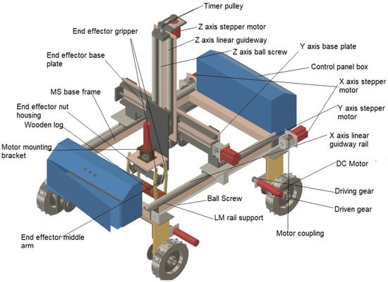
Figure 1.
Conceptual design of the proposed mobile manipulator.
In addition to the conceptual diagram, the development of solid and mathematical models has been crucial to comprehensively analyze the robot’s performance and behavior. These models consider mechanical properties, kinematics, and dynamics, providing valuable insights into how the robot functions. To derive kinematic solutions for the proposed design, an analytical approach has been adopted. Mathematical principles and equations are used to accurately determine the robot’s position, velocity, and acceleration. The implementation of these kinematic solutions in MATLAB enables simulations and performance assessment under various conditions, evaluating motion capabilities, workspace, and maneuverability. Moreover, a detailed dynamic analysis is conducted to understand the robot’s response to different operating conditions and external forces. This analysis assesses stability, control mechanisms, and potential areas for improvement. Additionally, dynamic analysis studies the robot’s behavior under varying external forces and loads, considering factors like inertia and torque. This leads to optimized control and motion planning strategies, refining the design for successful agricultural implementation.
2.2. Unique Contribution of This Paper
2.2.1. Design of the Vehicle Manipulator System (Mobile Manipulator)
The vehicle platform has been specifically designed to address challenges encountered in various terrains, including slippery ground. To ensure strong traction and pulling capability, the platform incorporates a skid-steering mobile base with a manipulator arm along with specialized end-effectors. This configuration enhances the vehicle’s stability and maneuverability. The serial–parallel hybrid manipulator type has been selected for the robotic manipulator due to its low inertia in the links and high payload-to-robot mass ratio. This design enables the manipulator to carry heavier loads efficiently. The mobile platform ensures that even when traversing difficult and irregular terrains, the vehicle remains stable without tipping over. Achieving precise motion and tracking control in parallel manipulators requires advanced controllers. As such, a sliding mode control (SMC) strategy has been proposed to achieve high-precision control for improved performance.
2.2.2. Motor Selection and Power Management
The motors used in the vehicle have been carefully selected based on factors such as power requirements, frictional coefficients, and the inclination of the terrain. High-powered motors are chosen to ensure easy navigation through uneven terrains. The vehicle incorporates a skid steer system, which provides increased traction, control, and maneuverability. The power supply for the vehicle’s operation is typically delivered through cables. However, considering the working conditions, there is a risk of the cables getting stuck, resulting in power and communication loss. To address this issue, a battery and RF controller arrangement has been implemented as an alternative power source and communication backup, ensuring continuous operation even in challenging situations.
These design considerations and implementations significantly enhance the functionality, reliability, and adaptability of the proposed agriculture robot, enabling it to perform effectively in diverse agricultural environments.
2.2.3. Integration of Robotic Sensor and Visual Feedback
To ensure continuous visual feedback in challenging environmental conditions like heavy rain, dense fog, and dust, a carefully chosen robotic sensor has been integrated into the vehicle. This sensor is strategically positioned to capture and process visual information even in adverse weather conditions. To address potential measurement errors caused by vibrations and slippery surfaces, vision-based image processing techniques have been implemented. These techniques enable the system to compensate for blurry images and utilize color and contrast information for precise distance and direction measurements. Additionally, an additional laser sensor has been included to enhance navigation accuracy. However, due to limited resources and constraints, the current version of the paper does not provide a detailed description of the sensor part, leaving it as a focus for future works.
3. Velocity and Force Analysis of Four-Wheel Skid-Steering System
The velocity and force analysis of the four-wheel skid-steering system is performed to understand the motion and forces involved in the system. The analysis is based on the Newton–Euler method, which considers the dynamic equations separately for each link and evaluates the results numerically.
Several assumptions are made for the analysis:
- The ground is assumed to be even without any surface shrinkage.
- The center of gravity (COG) of the robotic platform coincides with the geometrical center.
- All wheels move with a constant velocity without slippage.
- The manipulator is rigidly connected to the platform, and the links of the manipulator are also rigid.
- The vehicle frame and links are symmetrical in design, and the center of mass is considered as per the ideal symmetrical shape.
The kinematic model takes into account the vehicle’s motion by analyzing its velocity components and the correlation between the wheel’s angular velocity and the body-fixed velocities. The configuration of the skid-steering mobile base and its corresponding velocity components, as well as the wheel velocities, are illustrated in Figure 2.
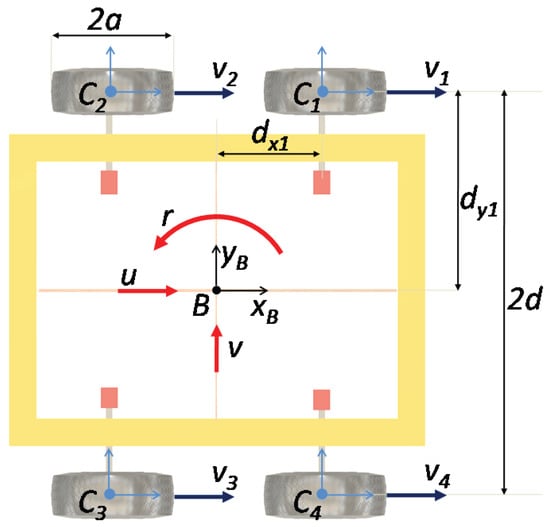
Figure 2.
Four-wheeled skid steering: velocity analysis.
In Figure 2, the geometry of the four-wheel skid-steering system is depicted, where ‘B’ represents the vehicle frame, ‘a’ is the radius of the wheel, and is the angle between the x-axis of frame B and the x-axis of wheel , and is the index representing the corresponding wheel. The tangential velocity of the wheel is given by
where represents the tangential velocity of wheel with respect to frame B, and is the angular velocity of the wheel.
The given equations describe the velocity and force analysis of the four-wheel skid-steering system. Let us break down the equations step by step.
The angular velocity of each wheel can be obtained by resolving along the x-axis and along the y-axis of the vehicle frame B:
By considering the angle and resolving velocities along the x-axis and y-axis of frame B, we can determine the velocity components in the vehicle frame B:
The velocity components along the x-axis and y-axis of frame B can be expressed as
By solving the above equations, the following relation is obtained, as follows:
The angular velocities of the wheels can be obtained by multiplying the transformation matrices:
Considering all four wheels as per the above equation, combining all four in the form of body-fixed velocities, it gives the following relation as given:
The linear and angular velocities of the vehicle can be calculated using the following matrix equation:
The input configuration matrix (W) is given as follows:
Further, the individual body-fixed velocities of the robot are as given below:
The force analysis, shown in Figure 3, involves the calculation of the forces acting on the vehicle due to its motion. The forces include the traction force, resistance force, and centripetal force. These forces influence the acceleration and overall performance of the vehicle.
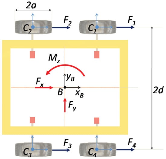
Figure 3.
Four-wheeled skid steering: force analysis.
The resultant forces in x- and y-axes and moment about the z-axis can be calculated by multiplying the force vector by a transformation matrix as given below:
The simulation results and analysis obtained for the circular trajectory tracking task are based on inverse dynamics (feed-forward control) to understand the behavior of the mobile platform. The forces at all four wheels are observed for better comprehension. Figure 4a illustrates the trajectory plot, demonstrating the circular path followed by the mobile platform. The trajectory is defined by the desired position variables for the vehicle’s x-axis motion (longitudinal motion) and for the vehicle’s y-axis motion (lateral motion). The results indicate that the platform successfully tracks the circular trajectory throughout the entire simulation duration of sixty seconds. In Figure 4b, the graph illustrates the behavior of the forces at all four wheels ( and ) during the circular trajectory following task. It is observed that during the initial phase, exhibits a lower magnitude compared to the other three forces. This difference in force magnitudes is expected as the mobile platform initiates the circular motion with zero actual velocity, while the commanded velocity is non-zero. As the platform proceeds along the circular path, the forces at all wheels vary to ensure that the platform maintains its desired trajectory. These variations in forces are essential to facilitate successful tracking of the circular path throughout the task.
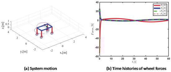
Figure 4.
Circular trajectory task performed by the skid−steering mobile platform.
These simulation results provide valuable insights into the force analysis and behavior of the mobile platform during a circular trajectory. They demonstrate the effectiveness of the model and its ability to follow the desired path while adjusting the forces at each wheel accordingly.
4. Kinematic Model of Proposed Vehicle Manipulator
The proposed agricultural robot can have one or two manipulator arms, and for this project, a decision was made to use one manipulator arm for simplicity and ease of access. There are numerous configurations available for manipulator’s arms, especially when positioning the end-effector in three-dimensional space. To determine the most suitable configuration for the proposed system, a preliminary analysis (type synthesis) was conducted, although the details are beyond the scope of this paper. The analysis revealed the four best configurations, consisting of three parallel manipulator configurations based on 3RUU [19], 3PRRR [75], and 3PUU [76,77] arrangements, and one serial manipulator configuration based on PPP arrangements. Considering space and other constraints, the gantry-type PPP serial manipulator was selected for the proposed system. The kinematic model of the designed PPP Cartesian manipulator consists of three limbs connected in series to a moving platform in a fixed base. To further elaborate on the kinematic model, let us consider the Cartesian coordinates of the end-effector concerning the fixed-body frame. The position of the end-effector in the Cartesian coordinate system is determined by three rigid bodies and three joint variables. The joint variables represent the motion of individual axes, while the rigid bodies represent the physical links of the robot. By controlling these joint variables, the manipulator can achieve various positions of the end-effector within its workspace. Overall, this model allows the robot to perform tasks in a coordinated manner, offering advantages such as improved precision, stiffness, and payload capacity.
To derive the kinematic model and conduct the kinematic analysis, it is essential to establish the frame arrangement of the vehicle manipulator system. This involves defining coordinate frames for each component and establishing their relationships. The frame selection should be carried out in a manner that simplifies the modeling process and enables a clear understanding of the kinematic relationships within the proposed system. A well-defined frame arrangement forms the foundation for accurately analyzing the system’s motion and aids in designing efficient control strategies for the vehicle manipulator. The arrangement of frames on the vehicle manipulator has been established relative to the inertial frame, as depicted in Figure 5. This frame arrangement defines the coordinate frames for each component, facilitating the analysis of the system’s motion and the establishment of kinematic relationships within the vehicle manipulator. The mobile base state variables for the proposed vehicle manipulator are denoted as x, y, and . The height of the vehicle, where the manipulator base is located, is represented as ‘h’. On the other hand, the manipulator joint variables include linear displacements denoted as , , and . These state and joint variables are essential for characterizing the motion and configuration of the vehicle manipulator system during its operation.
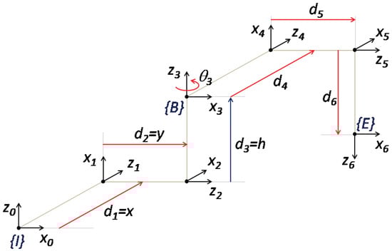
Figure 5.
Kinematic frame arrangement of the proposed vehicle manipulator.
Furthermore, Table 1 presents the Denavit–Hartenberg (DH) parameters for the proposed system, starting from the inertial frame and extending to the end-effector. This comprehensive information is crucial for accurately analyzing the manipulator’s kinematics and understanding its motion characteristics during operation.

Table 1.
DH parameters of the proposed vehicle manipulator.
Workspace Analysis
The proposed four-wheeled skid-steering mobile robot, integrated with a gantry-type Cartesian manipulator, underwent workspace analysis using MATLAB. The generated workspace, while the vehicle remains stationary, adopts a cuboidal shape based on the reach of the linear joints/actuators. This analysis offers valuable insights into the robot’s capabilities and limitations in terms of its operational workspace. In order to further assess and demonstrate the manipulator’s performance, end-effector displacements were recorded under various input conditions and analyzed using MATLAB. Figure 6 presents a portion of the analysis results, illustrating the variations in end-effector displacement across the workspace. These findings contribute to a comprehensive understanding of the robot’s range of motion and its capacity to execute diverse tasks within its operational workspace. Such workspace analysis outcomes are crucial in optimizing the manipulator’s design and control strategies, guaranteeing efficient and effective operation in agricultural applications. With this information at hand, the robot’s capabilities can be harnessed to their fullest potential, enhancing its utility in various agricultural tasks.
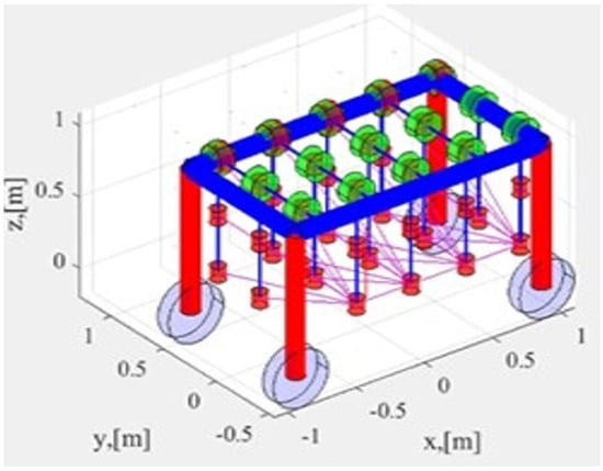
Figure 6.
Variations in end−effector displacements within the manipulator’s workspace.
5. Dynamic Model of the Proposed Vehicle Manipulator
The dynamic modeling of the vehicle manipulator can be approached in two ways. The first method, known as the decoupled model, treats the vehicle and manipulator as separate systems. This involves mapping their frame arrangement and Denavit–Hartenberg (DH) parameters. In this approach, the vehicle’s dynamic model is represented in its body-fixed moving frame. The second method involves considering a single coupled model. Here, the mobile base dynamics are expressed in the earth-fixed inertial frame. The dynamic equations of motion are then derived using Newton–Euler’s recursive method. Indeed, it is noteworthy that the dynamic modeling of the vehicle manipulator in a single-frame model offers simplifications that facilitate analysis while still capturing the essential interaction between the two subsystems. This approach proves particularly valuable in certain scenarios, as it provides a comprehensive understanding of the system’s behavior and allows for efficient study of the interplay between the vehicle and manipulator components.
In this work, both the manipulator and ground-based wheeled vehicle’s three degrees of freedom are modeled using Denavit–Hartenberg (DH) parameters. This approach presents a novelty compared to the traditional modeling of the Unified Vehicle Manipulator System, which explicitly incorporates dynamic coupling effects. In contrast, the dynamic coupling effects naturally arise when the vehicle’s degrees of freedom are modeled using DH parameters. By utilizing the DH parameters, the transformation matrix between each coordinate frame is obtained. The dynamic coupling of the proposed vehicle manipulator is evaluated using the recursive Newton–Euler algorithm. Through forward propagation, the angular velocity, velocity, and acceleration of each link are determined. Subsequently, backward propagation enables the determination of forces and moments acting on each link. As a result, the equations of motion can be derived within a single framework. The interactions between adjacent links involve forces and moments as follows:
In the given above equations, k represents the joint axis. The rotation matrix , force vector , and gravity force vector are defined. Additionally, represents the vector from the center of gravity of the link, represents the vector from joint k to , represents the total forces acting at the center of mass of the link, represents the total moments acting at the center of mass of the link, represents the linear acceleration vector, represents the angular acceleration vector, represents the linear velocity vector, represents the angular velocity vector, represents the mass of the link, represents the mass of the link located at the center of mass, represents the moment of inertia and added moment matrix of the link located at the center of mass, and represents the unit vector along the z-axis.
The forces and moments acting on the coordinate frame are the final forces and moments acting on the vehicle. It will include also the forces and moments created due to the manipulator as well as all the coupling effects. Then the terms of the equation can be rearranged into the following form:
where is the vector of linear and angular displacements (joint variables), is the vector of linear and angular velocities (joint velocities), is the vector of linear and angular accelerations (joint accelerations), is the inertia matrix of the vehicle manipulator system, and is the vector of other effects (this includes dynamic coupling, centripetal, Coriolis, gravity, and other effects).
The mathematical model of the mobile manipulator is then simulated in a MATLAB environment to analyze its dynamic behavior.
5.1. Robotic Dynamic (Motion) Control in Joint Space
In order to perform sensitive and repetitive tasks, the agriculture robot is equipped with an efficient motion control system to address uncertainties arising from load variations and external disturbances. The controller parameters are chosen based on experimentally verified values to minimize variations during real-time operation. For this purpose, a sliding mode control (SMC) technique is employed, which is a variable-structure nonlinear control method. SMC utilizes a discontinuous control signal to induce the system to “slide” along a cross-section of its normal behavior, thereby altering the system’s dynamics.
Let be the actual joint positions, be the actual joint velocities, be the inertial matrix, and be the other effects. The proposed motion control scheme is given as follows:
where is the proposed sliding surface (based on simple PD-like control), is the vector of position tracking errors, is the vector of velocity tracking errors, is a positive constant and defines the sliding surface characteristics. are the desired positions, velocities, and accelerations, respectively. is the controller gain matrix and it is a symmetric positive definite matrix.
5.2. Simulation Results and Discussions
Computer-based simulations are conducted to demonstrate the performance of the proposed vehicle manipulator and verify the effectiveness of the proposed motion control scheme. Additionally, to facilitate performance comparison, a conventional PD control with feedback linearization is also considered, as given below:
where and are the proportional and derivative controller gain matrices. These matrices are symmetric and positive definite, ensuring asymptotic stability for the system.
In the trajectory tracking task for the proposed vehicle manipulator system, the desired values of the system states are commanded to follow a given 3D spatial desired trajectory.
where , and are the desired mobile base generalized coordinates or vehicle states. , and are the desired manipulator linear displacements or joint space variables.
For this task, both PD and PD-like sliding mode controllers are implemented. The controller gain parameters are obtained through a real-time iterative process, and the corresponding gain values are provided in Table 2. These gain values are crucial for achieving effective trajectory tracking and validating the performance of the proposed motion control scheme.
Table 2.
Controller gain parameters.
The model was made to run for 9 s to capture the error under both scenarios. The error vs. time plot for PD control is shown in Figure 7. It has been noticed that during the PD control, the error value in terms of X and Y coordinate variation with the desired value has attained a value of 0.04 m and the error value remains fixed after two seconds, remaining constant for the rest of the defined path. However, during PD-like sliding mode control, the error value rapidly increased for one second and subsequently attained a value of zero after 5 s, as depicted in Figure 8.
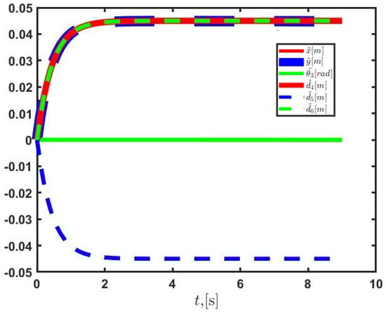
Figure 7.
Error vs. time plot for mobile manipulator for PD control.
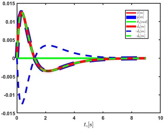
Figure 8.
Error vs. time plot for mobile manipulator for PD−like sliding mode control.
6. Simulation Analysis Using ADAMS
The performance of the proposed model was evaluated using ADAMS software through real-time simulation, as depicted in Figure 9. The SolidWorks design (3D model) of the mobile manipulator, including the terrain profile with varying ground elevations, was imported into ADAMS software. Contact forces between the ground and wheels were defined, along with a linear force acting on the center of mass of the robot.
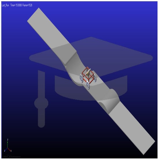
Figure 9.
Simulation test of model on ADAMS.
The model underwent simulation tests, subjecting it to two different linear force scenarios: 200 N and 220 N. The vehicle manipulator was commanded to follow a forward motion with constant forces on the x-axis, aiming to assess the vehicle’s behavior with the proposed design and construction on rough terrain and determine the suitable actuator for the mobile base. The tests were conducted for 15 s, and displacement, velocity, and acceleration curves were plotted against time to evaluate the model’s performance.
Figure 10 illustrates the performance of the model under a linear force of 200 N. It can be observed that the model faced difficulty negotiating the high ground, resulting in a deceleration after approximately 12 s. The center of mass of the frame exhibited a continuous increase until 12 s, after which it started moving in the reverse direction.
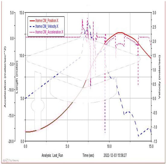
Figure 10.
Mobile manipulator center of mass, velocity, and acceleration graph with respect to time under 200 N of force.
In the subsequent attempt with a linear force of 220 N, as shown in Figure 11, the manipulator successfully managed to overcome a 45-degree slope gradient. Notably, there was a sudden rise in velocity and acceleration during the downward movement when negotiating the slope, while the acceleration and velocity values decreased when negotiating the upward slopes.
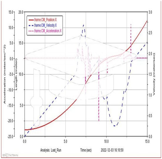
Figure 11.
Mobile manipulator center of mass, velocity, and acceleration graph with respect to time under 220 N of force.
These simulation analyses provide valuable insights into the performance and capabilities of the proposed model. They allow for the identification of potential limitations and areas for improvement, aiding in the refinement of the design and optimization of the robot’s performance in real-world agricultural environments. Additionally, the ADAMS model is utilized to validate the dynamic model derived using Newton–Euler’s method. This validation process ensures the accuracy and reliability of the proposed model, thereby enabling its application in model-based system control schemes.
7. Functional Prototype
The prototype model of the system has been developed in hardware, taking into account the findings from mathematical modeling, software simulation, and preliminary structural analysis. The design of the base frame was initiated using mild steel, with dimensions of 63 mm in thickness, 1300 mm in length, and 900 mm in breadth. The choice of mild steel was made due to its high strength, which provides structural stability and balance to the joints. Compared to aluminum, steel offers superior strength, making it suitable for the requirements of the system.
To ensure effective navigation through uneven terrains, high-powered motors were selected for the vehicle. These motors provide the necessary power to overcome obstacles and operate smoothly in challenging environments. The implementation of a skid-steering system further enhances traction, control, and maneuverability, enabling the robot to adapt to different terrains effectively.
One important feature of the PPP-based mobile manipulator design is its inherent stability. By establishing the home position of the end-effector assembly prior to the start of the mobile platform, the system is configured to prevent tipping over, even when encountering difficult and irregular terrains. This proactive approach to maintaining stability enhances the overall performance and safety of the robot during operation.
By considering factors such as material selection, motor power, and stability mechanisms, the prototype model has been designed to meet the requirements of agricultural operations in various environments. This hardware development phase marks an important step towards further testing, optimization, and eventual deployment of the agriculture robot.
The proposed agriculture robot consists of several key assemblies that enable its functionality and movement. These assemblies include the X-axis assembly, Y-axis assembly, Z-axis assembly, wheels assembly, and the end-effector.
- The X-axis assembly allows the end effector to travel along the length of the frame. It utilizes linear guide rails and ball-bearing carriages for smooth translation and is shown in Figure 12. Ball screw mechanisms controlled by stepper motors are employed to move the carriages along the X-axis.
- The Y-axis assembly enables lateral translation of the end-effector. It consists of a base plate, guide rails, ball-bearing carriages, and a ball screw arrangement driven by a stepper motor. This assembly facilitates movement in the lateral direction and is shown in Figure 13.
- The Z-axis assembly is attached to the Y-axis assembly and is responsible for the vertical translation. It consists of guide rails, ball bearings, and a ball screw mechanism connected to a motor. This assembly allows for the vertical movement of the end-effector and is shown in Figure 14.
- The wheels assembly includes four solid rubber wheels with a load-carrying capacity of 500 kg. The wheels are mounted to the base frame using L brackets and drive the entire assembly set. These wheels enable the robot to move and navigate through different terrains.

Figure 12.
X-axis sub-assembly.
Figure 12.
X-axis sub-assembly.


Figure 13.
Y-axis sub-assembly.
Figure 13.
Y-axis sub-assembly.


Figure 14.
Z-axis sub-assembly.
Figure 14.
Z-axis sub-assembly.

- The end-effector is a crucial component of the robot and can be customized for various agricultural operations. The designed end effector is specifically used for picking loads, such as baskets containing fruits or vegetables, and is shown in Figure 15. It operates using a lead screw mechanism to open and grab objects. Additionally, there are conceptual end-effectors being considered for weed picking, pruning operations, and plucking fruits from trees.

Figure 15.
End-effector assembly.
Figure 15.
End-effector assembly.

The paper presents two types of end-effectors designed specifically for different types of fruits in agricultural operations based on parallel mechanisms/manipulators.
The first type of end-effector, shown in Figure 16, is designed for cylindrical-shaped fruits. It utilizes a parallel manipulation configuration and is operated by a single actuator. This end-effector is designed to effectively grip and pick cylindrical fruits, such as bananas or cucumbers. The lead screw mechanism allows the arms of the end-effector to open and close, providing a secure grip on the fruits.
The second type of end-effector, shown in Figure 17, is designed for spherical-shaped fruits. Similar to the previous design, this end-effector also employs a parallel manipulation configuration and a single actuator. It is specifically tailored to handle spherical fruits like apples or oranges. The end-effector uses a three-fingered gripper mechanism, operated by a scissor lift mechanism, to grasp and pick the spherical fruits with precision.
The same end-effector can also be used as a weeding mechanism that incorporates an additional aluminum rail, positioned laterally over the cart, to which the gripper and slider are attached. This rail can be longitudinally translated using the ball screw mechanism located along the cart’s longitudinal rail on both sides. The design employs three ball screws for the translational motion of the components. The ball screw converts rotational motion into linear motion. Figure 17 presents the CAD model of the ball screw assembly. The rail is supported by ball-bearing carriages, enabling smooth translation motion. These carriages are guided by guide rails placed on T-slots within the cart. A slider is connected to the lateral rail, facilitating the vertical movement of the gripper to reach weed roots. The slider is laterally translated along the rail using a ball screw mechanism.

Figure 16.
End-effector designed to carry a heavy load and ideal for all types of cylindrical-shaped fruits.
Figure 16.
End-effector designed to carry a heavy load and ideal for all types of cylindrical-shaped fruits.


Figure 17.
End-effector designed for spherical-shaped fruits.
Figure 17.
End-effector designed for spherical-shaped fruits.

As depicted in Figure 17, telescopic slides are affixed to the lateral frame using ball-bearing carriages and guideways. A close-up view of the telescopic slides is shown in Figure 17. The gripper, illustrated in Figure 17, is mounted on these telescopic slides, allowing for height adjustment according to specific requirements. The end-effector of the gripper consists of a three-fingered parallel gripper design.
Both end-effectors are designed to accommodate the specific shape and size of the target fruits, ensuring efficient and reliable picking operations in agricultural settings. The use of parallel manipulation configurations and single actuators allows for simplified control and operation of the end-effectors, enhancing the overall performance of the agriculture robot.
The combination of these assemblies and the end-effector allows the proposed agriculture robot to perform various tasks efficiently in agricultural settings.
Fabrication and Making of Prototype
During the fabrication of the prototype, a combination of off-the-shelf components and custom-designed parts was utilized. The following steps were undertaken:
- Procurement of Components: Wheels, bearings, and chain sprockets, among other readily available components, were procured from suppliers.
- Design and Manufacture: Components such as L brackets and wheel shafts were designed using CAD software and manufactured according to the specifications provided in the CAD drawings.
- Panel Boxes: Two-panel boxes were specifically designed to house electronic components, including motor drivers and batteries, ensuring proper organization and protection.
- Assembly: Rail assemblies were fixed onto the base frame, while wheel assemblies were mounted on L brackets. This arrangement facilitated the mobility of the robot.
- Manual Testing: The manual movement of all axes was manually tested by rotating the ball screw for each axis. The tire-free movements were examined by pushing and pulling the mobile platform.
- End Effector: The ball screw arrangement for the end-effector was manually tested and subsequently mounted on the Z-axis.
- Calibration: The complete structure underwent calibration to ensure smooth and unhindered movement of components along the X-, Y-, and Z-axes.
- Testing of Electronic Components: The functionality of individual motor drives for the X-, Y-, and Z-axes, along with end-effector movement, was tested. This involved checking the specifications and performance of electronic components.
To provide further details on the electronic components used during the fabrication of the prototype, refer to Table 3, which outlines their specifications.
Table 3.
Specifications of electronic components.
By following these steps and ensuring the proper integration and functioning of components, the prototype of the agriculture robot was successfully fabricated and is shown in Figure 18, laying the foundation for further testing and refinement.
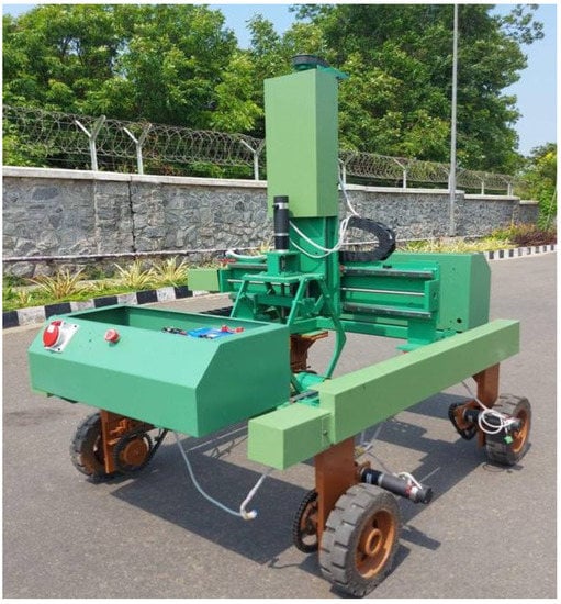
Figure 18.
In-house fabricated prototype of the agricultural mobile manipulator.
The fabricated prototype’s functionality is demonstrated in the lab environment by successfully picking up a bottle guard from flat ground. The sequence of the robot’s motion for this task is depicted in Figure 19. This demonstration confirms that the proposed robot is performing the intended task according to its design. However, further enhancements in sensor integration and overall system integration are required to make it a more viable and practical solution. These improvements will enhance the robot’s capabilities and ensure its reliable performance in real-world applications.
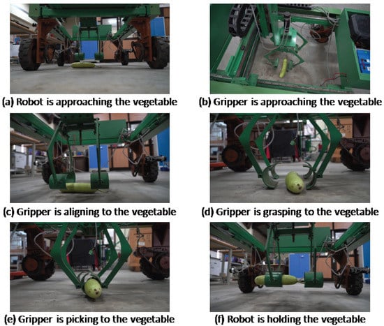
Figure 19.
Demonstration of a vegetable-picking task using the proposed vehicle manipulator.
8. Conclusions
Robotic technology offers numerous opportunities to enhance agricultural output in multiple dimensions. The farming industry should explore the potential use of advanced prototypes as versatile robotic platforms capable of handling various agricultural tasks. By making minor modifications, these platforms can be utilized for repetitive farming activities, significantly boosting overall productivity while saving time and reducing the need for manual labor. To enable efficient operations, the platform can be equipped with wide-view and narrow-view cameras for real-time live streaming. Leveraging AI-based tools, it can effectively identify fruits and weeds, streamlining the farming process. The current prototype utilizes a four-wheel skid-steering mechanism, which can be further improved by incorporating a steering mechanism for all four wheels, enhancing its versatility and making it more holonomic.
Moreover, the platform is designed with an end-effector capable of lifting heavy fruits like watermelon and muskmelon. Its stability is exceptional, and the gantry-type Cartesian manipulator design inherently allows the overall system to handle heavy loads in agricultural landscapes. The proposed vehicle manipulator prototype has successfully demonstrated its intended functionality in terms of handling heavy fruits and maneuvering flat rough terrains and shows great potential for deployment in agriculture fields, especially with iterative design optimization. Overall, harnessing the potential of robotic technology in agriculture holds significant promise for improving productivity, efficiency, and ultimately, the success of the industry.
The proposed system is designed to operate on flat ground and rough terrains with smaller-sized bumps, typically up to 10 cm to 15 cm in height. It is configured to operate at a limited speed of 0.5 m/s. The current design focuses on handling heavy fruits, weed removal, and pruning operations. However, the end-effector designs can be adaptable for multiple purposes. Currently, the robotic system has a gantry-type structure, which is suitable for smaller-sized plants, and it utilizes a bottom-looking sensor configuration. Nevertheless, with appropriate modifications, the proposed system can be extended to perform fruit harvesting in taller trees with heights up to 3 m. This extension can be achieved by enhancing the design to enable the vertical joint of the manipulator to move in an upward direction, facilitating harvesting at elevated heights. Furthermore, the mobile base of the system utilizes skid steering and is equipped with four powered solid rubber wheels. This configuration may limit the maneuverability of the robot, and the absence of an active suspension system restricts its operation in hilly and rough terrains. However, by incorporating a proper suspension system, the robot’s capabilities can be significantly enhanced. An active suspension system would enable the robot to navigate more efficiently on uneven and challenging terrains, including hilly landscapes and rough surfaces. With the addition of a suitable suspension mechanism, the robot’s stability and adaptability will improve, allowing it to traverse various terrains with ease and perform agricultural tasks in diverse environments. This enhancement would make the robot more versatile and suitable for a wider range of agricultural applications.
Author Contributions
S.K.: Conceptualization, Methodology, Software, Investigation, Writing—original draft, Writing—review and editing. S.M.: Conceptualization, Methodology, Software, Writing—original draft, review and editing, Supervision and Visualization. V.S.: Validation, Writing—review & editing, Project administration and Funding acquisition. All authors have read and agreed to the published version of the manuscript.
Funding
The study was supported by a grant from the Russian Science Foundation No. 22-19-20153, https://rscf.ru/project/22-19-20153/ (accessed on 25 July 2023 ) and the Government of the Belgorod Region, Agreement No. 4.
Data Availability Statement
Not applicable.
Conflicts of Interest
The authors affirm that there are no conflicts of interest to disclose. Additionally, the funders played no part in the study’s design, data collection, analysis, manuscript writing, or the decision to publish the findings.
References
- Cheng, C.; Fu, J.; Su, H.; Ren, L. Recent Advancements in Agriculture Robots: Benefits and Challenges. Machines 2023, 11, 48. [Google Scholar] [CrossRef]
- Shamshiri, R.R.; Weltzien, C.; Hameed, I.A.; Yule, I.J.; Grift, T.E.; Balasundram, S.K.; Pitonakova, L.; Ahmad, D.; Chowdhary, G. Research and development in agricultural robotics: A perspective of digital farming. Int. J. Agric. Biol. Eng. 2018, 11, 1–14. [Google Scholar] [CrossRef]
- Martin, T.; Gasselin, P.; Hostiou, N.; Feron, G.; Laurens, L.; Purseigle, F.; Ollivier, G. Robots and transformations of work in farm: A systematic review of the literature and a research agenda. Agron. Sustain. Dev. 2022, 42, 66. [Google Scholar] [CrossRef]
- Lu, Y.; Pavón, J.; Emmi, L.; Gonzalez-de-Soto, M.; Pajares, G.; Gonzalez-de-Santos, P. New Trends in Robotics for Agriculture: Integration and Assessment of a Real Fleet of Robots. Sci. World J. 2014, 2014, 404059. [Google Scholar] [CrossRef]
- White, J.W.; Andrade-Sanchez, P.; Gore, M.A.; Bronson, K.F.; Coffelt, T.A.; Conley, M.M.; Feldmann, K.A.; French, A.N.; Heun, J.T.; Hunsaker, D.J.; et al. Field-based phenomics for plant genetics research. Field Crop. Res. 2012, 133, 101–112. [Google Scholar] [CrossRef]
- Marinoudi, V.; Sørensen, C.G.; Pearson, S.; Bochtis, D. Robotics and labour in agriculture. A context consideration. Biosyst. Eng. 2019, 184, 111–121. [Google Scholar] [CrossRef]
- Mahmud, M.S.A.; Abidin, M.S.Z.; Emmanuel, A.A.; Hasan, H.S. Robotics and automation in agriculture: Present and future applications. Appl. Model. Simul. 2020, 4, 130–140. [Google Scholar]
- Wang, F.; Urquizo, R.C.; Roberts, P.; Mohan, V.; Newenham, C.; Ivanov, A.; Dowling, R. Biologically inspired robotic perception-action for soft fruit harvesting in vertical growing environments. Precis. Agric. 2023, 24, 1072–1096. [Google Scholar] [CrossRef]
- Malyshev, D.; Rybak, L.; Gaponenko, E.; Voloshkin, A. Algorithm for Determining the Singularity-Free and Interference-Free Workspace of a Robotic Platform for Fruit Harvesting. Eng. Proc. 2023, 33, 33. [Google Scholar]
- Rong, J.; Fu, J.; Zhang, Z.; Yin, J.; Tan, Y.; Yuan, T.; Wang, P. Development and Evaluation of a Watermelon-Harvesting Robot Prototype: Vision System and End-Effector. Agronomy 2022, 12, 2836. [Google Scholar] [CrossRef]
- Yoshida, T.; Onishi, Y.; Kawahara, T.; Fukao, T. Automated harvesting by a dual-arm fruit harvesting robot. Robomech. J. 2022, 9, 19. [Google Scholar] [CrossRef]
- Khare, D.; Cherussery, S.; Mohan, S. Investigation on design and control aspects of a new autonomous mobile agricultural fruit harvesting robot. Proc. Inst. Mech. Eng. Part C J. Mech. Eng. Sci. 2022, 236, 9966–9977. [Google Scholar] [CrossRef]
- Bloch, V.; Degani, A.; Bechar, A. A methodology of orchard architecture design for an optimal harvesting robot. Biosyst. Eng. 2018, 166, 127–136. [Google Scholar] [CrossRef]
- Shamshiri, R.R.; Hameed, I.A.; Karkee, M.; Weltzien, C. Robotic harvesting of fruiting vegetables: A simulation approach in V-REP, ROS and MATLAB. Proc. Autom.-Agric.-Secur. Food Supply Future Gener. 2018, 126, 81–105. [Google Scholar]
- Iida, M.; Harada, S.; Sasaki, R.; Zhang, Y.; Asada, R.; Suguri, M.; Masuda, R. Multi-combine robot system for rice harvesting operation. In Proceedings of the 2017 ASABE Annual International Meeting, Spokane, WA, USA, 16–19 July 2017; p. 1. [Google Scholar]
- Barth, R.; Hemming, J.; van Henten, E.J. Design of an eye-in-hand sensing and servo control framework for harvesting robotics in dense vegetation. Biosyst. Eng. 2016, 146, 72–83. [Google Scholar] [CrossRef]
- Eizicovits, D.; van Tuijl, B.; Berman, S.; Edan, Y. Integration of perception capabilities in gripper design using graspability maps. Biosyst. Eng. 2016, 146, 100–112. [Google Scholar] [CrossRef]
- Longo, D.; Muscato, G. Design and simulation of two robotic systems for automatic artichoke harvesting. Robotics 2013, 2, 218–229. [Google Scholar] [CrossRef]
- Šlajpah, S.; Munih, M.; Mihelj, M. Mobile Robot System for Selective Asparagus Harvesting. Agronomy 2023, 13, 1766. [Google Scholar] [CrossRef]
- Arad, B.; Balendonck, J.; Barth, R.; Ben-Shahar, O.; Edan, Y.; Hellström, T.; Hemming, J.; Kurtser, P.; Ringdahl, O.; Tielen, T.; et al. Development of a sweet pepper harvesting robot. J. Feild Robot. 2020, 37, 1027–1039. [Google Scholar] [CrossRef]
- Hemming, J.; Bac, C.W.; van Tuijl, B.A.; Barth, R.; Bontsema, J.; Pekkeriet, E.J.; Van Henten, E. A Robot for Harvesting Sweet-Pepper in Greenhouses; AgEng: Zurich, Switzerland, 2014. [Google Scholar]
- Wang, L.L.; Zhao, B.; Fan, J.W.; Hu, X.A.; Wei, S.; Li, Y.S.; Zhou, Q.; Wei, C. Development of a tomato harvesting robot used in greenhouse. Int. J. Agric. Biol. Eng. 2017, 10, 140–149. [Google Scholar]
- Jun, J.; Kim, J.; Seol, J.; Kim, J.; Son, H.I. Towards an Efficient Tomato Harvesting Robot: 3D Perception, Manipulation, and End-Effector. IEEE Access 2021, 9, 17631–17640. [Google Scholar] [CrossRef]
- Van Henten, E.J.; Hemming, J.; Van Tuijl, B.A.J.; Kornet, J.G.; Meuleman, J.; Bontsema, J.; Van Os, E.A. An autonomous robot for harvesting cucumbers in greenhouses. Auton. Robot. 2002, 13, 241–258. [Google Scholar] [CrossRef]
- Xiong, Y.; Ge, Y.; Grimstad, L.; From, P.J. An autonomous strawberry-harvesting robot: Design, development, integration, and field evaluation. J. Field Robot. 2020, 37, 202–224. [Google Scholar] [CrossRef]
- Woo, S.; Uyeh, D.D.; Kim, J.; Kim, Y.; Kang, S.; Kim, K.C.; Lee, S.Y.; Ha, Y.; Lee, W.S. Analyses of Work Efficiency of a Strawberry-Harvesting Robot in an Automated Greenhouse. Agronomy 2020, 10, 1751. [Google Scholar] [CrossRef]
- Hayashi, S.; Shigematsu, K.; Yamamoto, S.; Kobayashi, K.; Kohno, Y.; Kamata, J.; Kurita, M. Evaluation of a strawberry-harvesting robot in a field test. Biosyst. Eng. 2010, 105, 160–171. [Google Scholar] [CrossRef]
- Zhang, K.; Lammers, K.; Chu, P.; Li, Z.; Lu, R. System design and control of an apple harvesting robot. Mechatronics 2021, 79, 102644. [Google Scholar] [CrossRef]
- Silwal, A.; Davidson, J.R.; Karkee, M.; Mo, C.; Zhang, Q.; Lewis, K. Design, integration, and field evaluation of a robotic apple harvester. J. Feild Robot. 2017, 34, 1140–1159. [Google Scholar] [CrossRef]
- Zhao, D.; Lv, J.; Ji, W.; Zhang, Y.; Chen, Y. Design and control of an apple harvesting robot. Biosyst. Eng. 2011, 110, 112–122. [Google Scholar] [CrossRef]
- Roldán, J.J.; del Cerro, J.; Garzón-Ramos, D.; Garcia-Aunon, P.; Garzón, M.; De León, J.; Barrientos, A. Robots in agriculture: State of art and practical experiences. In Service Robots; IntechOpen: Rijeka, Croatia, 2018; pp. 67–90. [Google Scholar]
- Avgoustaki, D.D.; Avgoustakis, I.; Miralles, C.C.; Sohn, J.; Xydis, G. Autonomous Mobile Robot with Attached Multispectral Camera to Monitor the Development of Crops and Detect Nutrient and Water Deficiencies in Vertical Farms. Agronomy 2022, 12, 2691. [Google Scholar] [CrossRef]
- Seo, D.; Cho, B.-H.; Kim, K.-C. Development of Monitoring Robot System for Tomato Fruits in Hydroponic Greenhouses. Agronomy 2021, 11, 2211. [Google Scholar] [CrossRef]
- Zhang, W.; Miao, Z.; Li, N.; He, C.; Sun, T. Review of Current Robotic Approaches for Precision Weed Management. Curr. Robot. Rep. 2022, 3, 139–151. [Google Scholar] [CrossRef]
- Morara, G.; Baldassarri, A.; Diepenbruck, J.; Bruckmann, T.; Carricato, M. Design of a Weed-Control Mobile Robot Based on Electric Shock. In Proceedings of the Symposium on Robot Design, Dynamics and Control, Udine, Italy, 4–7 July 2022; pp. 220–227. [Google Scholar]
- Raja, R.; Nguyen, T.T.; Slaughter, D.C.; Fennimore, S.A. Real-time robotic weed knife control system for tomato and lettuce based on geometric appearance of plant labels. Biosyst. Eng. 2020, 194, 152–164. [Google Scholar] [CrossRef]
- Oberti, R.; Marchi, M.; Tirelli, P.; Calcante, A.; Iriti, M.; Tona, E.; Hočevar, M.; Baur, J.; Pfaff, J.; Schütz, C.; et al. Selective spraying of grapevines for disease control using a modular agricultural robot. Biosyst. Eng. 2016, 146, 204–214. [Google Scholar] [CrossRef]
- Åstrand, B.; Baerveldt, A.-J. An agricultural mobile robot with vision-based perception for mechanical weed control. Auton. Robot. 2002, 13, 21–35. [Google Scholar] [CrossRef]
- Blasco, J.; Aleixos, N.; Roger, J.M.; Rabatel, G.; Moltó, E. AE—Automation and emerging technologies: Robotic weed control using machine vision. Biosyst. Eng. 2002, 83, 149–157. [Google Scholar] [CrossRef]
- Kitić, G.; Krklješ, D.; Panić, M.; Petes, C.; Birgermajer, S.; Crnojević, V. Agrobot Lala—An Autonomous Robotic System for Real-Time, In-Field Soil Sampling, and Analysis of Nitrates. Sensors 2022, 22, 4207. [Google Scholar] [CrossRef]
- Blender, T.; Buchner, T.; Fernandez, B.; Pichlmaier, B.; Schlegel, C. Managing a mobile agricultural robot swarm for a seeding task. In Proceedings of the IECON 2016—42nd Annual Conference of the IEEE Industrial Electronics Society, Florence, Italy, 23–26 October 2016; pp. 6879–6886. [Google Scholar]
- Hallik, L.; Šarauskis, E.; Kazlauskas, M.; Bručienė, I.; Mozgeris, G.; Steponavičius, D.; Tõrra, T. Proximal Sensing Sensors for Monitoring Crop Growth. In Information and Communication Technologies for Agriculture—Theme I: Sensors; Springer: Cham, Switzerland, 2022; pp. 43–97. [Google Scholar]
- Heravi, A.; Ahmad, D.A.; Hameed, I.; Ramin, S.R.K.; Balasundram, S.; Yamin, M. Development of a Field Robot Platform for Mechanical Weed Control in Greenhouse Cultivation of Cucumber. Agric. Robot. Intechopen 2019, 2, 80935. [Google Scholar] [CrossRef]
- Bechar, A.; Vigneault, C. Agricultural robots for field operations, Concepts, and components. Biosyst. Eng. 2016, 149, 94–111. [Google Scholar] [CrossRef]
- Cruz Ulloa, C.; Krus, A.; Barrientos, A.; Del Cerro, J.; Valero, C. Robotic fertilisation using localisation systems based on point clouds in strip-cropping fields. Agronomy 2020, 11, 11. [Google Scholar] [CrossRef]
- Hassan, A.; Abdullah, H.M.; Farooq, U.; Shahzad, A.; Asif, R.M.; Haider, F.; Rehman, A.U. A wirelessly controlled robot-based smart irrigation system by exploiting Arduino. J. Robot. Control 2021, 2, 29–34. [Google Scholar] [CrossRef]
- de Soto, G.M.; Emmi, L.; Perez, R.M.; Aguera, J.; Gonzalez-de-Santos, P. Autonomous systems for precise spraying Evaluation of a robotised patch sprayer. Biosyst. Eng. 2016, 146, 167–181. [Google Scholar]
- Adamides, G.; Katsanos, C.; Parmet, Y.; Christou, G.; Xenos, M.; Hadzilacos, T.; Edan, Y. HRI usability evaluation of interaction modes for a teleoperated agricultural robotic sprayer. Appl. Ergon. 2017, 62, 237–246. [Google Scholar] [CrossRef] [PubMed]
- Hejazipoor, H.; Massah, J.; Soryani, M.; Vakilian, K.A.; Chegini, G. An intelligent spraying robot based on plant bulk volume. Comput. Electron. Agric. 2021, 180, 105859. [Google Scholar] [CrossRef]
- Meshram, A.T.; Vanalkar, A.V.; Kalambe, K.B.; Badar, A.M. Pesticide Spraying Robot for Precision Agriculture: A Categorical Literature Review and Future Trends. J. Field Robot. 2022, 39, 153–171. [Google Scholar] [CrossRef]
- Zahid, A.; Mahmud, M.S.; He, L.; Choi, D.; Heinemann, P.; Schupp, J. Development of an integrated 3R end-effector with a cartesian manipulator for pruning apple trees. Comput. Electron. Agric. 2020, 179, 105837. [Google Scholar] [CrossRef]
- Ishigure, Y.; Hirai, K.; Kawasaki, H. A pruning robot with a power-saving chainsaw drive. In Mechatronics and Automation (ICMA). In Proceedings of the 2013 IEEE International Conference, Takamatsu, Japan, 4–7 August 2013; pp. 1222–1226. [Google Scholar]
- Kawasaki, H.; Murakami, S.; Kachi, H.; Ueki, S. Novel climbing method of pruning robot. In Proceedings of the 2008 SICE Annual Conference, Chofu, Japan, 20–22 August 2008; pp. 160–163. [Google Scholar]
- Zhang, C.; Gao, H.; Zhou, J.; Cousins, A.; Pumphrey, M.O.; Sankaran, S. 3D robotic system development for high-throughput crop phenotyping. IFAC-PapersOnLine 2016, 49, 242–247. [Google Scholar] [CrossRef]
- Ruckelshausen, A.; Biber, P.; Dorna, M.; Klose, R.; Linz, A. BoniRob—An autonomous field robot platform for individual plant phenotyping. Precis. Agric. 2009, 9, 841. [Google Scholar]
- Tourrette, T.; Deremetz, M.; Naud, O.; Lenain, R.; Laneurit, J.; De Rudnicki, V. Close coordination of mobile robots using radio beacons: A new concept aimed at smart spraying in agriculture. In Proceedings of the 2018 IEEE/RSJ International Conference on Intelligent Robots and Systems (IROS), Madrid, Spain, 1–5 October 2018; pp. 7727–7734. [Google Scholar]
- Conesa-Muñoz, J.; Bengochea-Guevara, J.M.; Andujar, D.; Ribeiro, A. Route planning for agricultural tasks: A general approach for fleets of autonomous vehicles in site-specific herbicide applications. Comput. Electron. Agric. 2016, 127, 204–220. [Google Scholar] [CrossRef]
- Weiss, U.; Biber, P. Plant detection and mapping for agricultural robots using a 3D LIDAR sensor. Robot. Auton. Syst. 2011, 59, 266–272. [Google Scholar] [CrossRef]
- Saeed, R.A.; Tomasi, G.; Carabin, G.; Vidoni, R.; von Ellenrieder, K.D. Conceptualization and Implementation of a Reconfigurable Unmanned Ground Vehicle for Emulated Agricultural Tasks. Machines 2022, 10, 817. [Google Scholar] [CrossRef]
- Shamshiri, R.; Wan Ismail, W.I. Design and Simulation of Control Systems for a Field Survey Mobile Robot Platform. Res. J. Appl. Sci. Eng. Technol. 2013, 6, 2308–2314. [Google Scholar] [CrossRef]
- Cariou, C.; Lenain, R.; Thuilot, B.; Berducat, M. Automatic guidance of a four-wheel-steering mobile robot for accurate field operations. J. Field Robot. 2009, 26, 505–517. [Google Scholar] [CrossRef]
- English, A.; Ross, P.; Ball, D.; Corke, P. Vision-based guidance for robot navigation in agriculture. in Robotics and Automation (ICRA), 2014. IEEE Int. Conf. 2014, 2014, 1694–1697. [Google Scholar]
- Bak, T.; Jakobsen, H. Agricultural robotic platform with four-wheel steering for weed detection. Biosyst. Eng. 2004, 87, 126–135. [Google Scholar] [CrossRef]
- Yin, X.; Noguchi, N. Development and evaluation of a general-purpose electric off-road robot based on agricultural navigation. Int. J. Agric. Biol. Eng. 2014, 7, 15–20. [Google Scholar]
- Qi, H.X.; Banhazi, T.M.; Zhang, Z.G.; Low, T.; Brookshaw, I.J. Preliminary laboratory test on navigation accuracy of an autonomous robot for measuring air quality in livestock buildings. Int. J. Agric. Biol. Eng. 2016, 9, 30–39. [Google Scholar]
- Martin, J.; Ansuategi, A.; Maurtua, I.; Gutierrez, A.; Obregón, D.; Casquero, O.; Marcos, M. A Generic ROS-Based Control Architecture for Pest Inspection and Treatment in Greenhouses Using a Mobile Manipulator. IEEE Access 2021, 9, 94981–94995. [Google Scholar] [CrossRef]
- Roshanianfard, A.; Noguchi, N. Pumpkin harvesting robotic end-effector. Comput. Electron. Agric. 2020, 174, 105503. [Google Scholar] [CrossRef]
- Kurita, H.; Iida, M.; Cho, W.; Suguri, M. Rice Autonomous Harvesting: Operation Framework. J. Field Robot. 2017, 34, 1084–1099. [Google Scholar] [CrossRef]
- Zhang, Z.; Noguchi, N.; Ishii, K.; Yang, L.; Zhang, C. Development of a Robot Combine Harvester for Wheat and Paddy Harvesting. IFAC Proc. Vol. 2013, 46, 45–48. [Google Scholar] [CrossRef]
- Gharakhani, H.; Thomasson, J.A.; Lu, Y. An end-effector for robotic cotton harvesting. Smart Agric. Technol. 2022, 2, 100043. [Google Scholar] [CrossRef]
- Wang, S.; Zhou, H.; Zhang, C.; Ge, L.; Li, W.; Yuan, T.; Zhang, W.; Zhang, J. Design, development and evaluation of latex harvesting robot based on flexible Toggle. Robot. Auton. Syst. 2022, 147, 103906. [Google Scholar] [CrossRef]
- Rong, J.; Wang, P.; Yang, Q.; Huang, F. A Field-Tested Harvesting Robot for Oyster Mushroom in Greenhouse. Agronomy 2021, 11, 1210. [Google Scholar] [CrossRef]
- Yi, J.; Wang, H.; Zhang, J.; Song, D.; Jayasuriya, S.; Liu, J. Kinematic Modeling and Analysis of SkidSteered Mobile Robots With Applications to Low-Cost Inertial-Measurement-Unit-Based Motion Estimation. IEEE Trans. Robot. 2009, 25, 1087–1097. [Google Scholar]
- Chebrolu, N.; Lottes, P.; Schaefer, A.; Winterhalter, W.; Burgard, W.; Stachniss, C. Agricultural robot dataset for plant classification, localization and mapping on sugar beet fields. Int. J. Robot. Res. 2017, 36, 1045–1052. [Google Scholar] [CrossRef]
- Sunilkumar, P.; Choudhury, R.; Mohan, S.; Rubak, L. Dynamics and motion control of a three degree of freedom 3-PRRR parallel manipulator. Mech. Mach. Sci. 2020, 89, 103–111. [Google Scholar]
- Lu, S.; Li, Y.M.; Ding, B.X. Multi-objective Dimensional Optimization of a 3-DOF Translational PKM Considering Transmission Properties. Int. J. Autom. Comput. 2019, 16, 748–760. [Google Scholar] [CrossRef]
- Lu, S.; Ding, B.; Li, Y. Minimum-jerk trajectory planning pertaining to a translational 3-degree-of-freedom parallel manipulator through piecewise quintic polynomials interpolation. Adv. Mech. Eng. 2014, 12, 1–8. [Google Scholar] [CrossRef]


Disclaimer/Publisher’s Note: The statements, opinions and data contained in all publications are solely those of the individual author(s) and contributor(s) and not of MDPI and/or the editor(s). MDPI and/or the editor(s) disclaim responsibility for any injury to people or property resulting from any ideas, methods, instructions or products referred to in the content. |
© 2023 by the authors. Licensee MDPI, Basel, Switzerland. This article is an open access article distributed under the terms and conditions of the Creative Commons Attribution (CC BY) license (https://creativecommons.org/licenses/by/4.0/).