Review

Overview of Jamming Technology for Satellite Navigation

College of Electronic Science, National University of Defense Technology, Changsha 410000, China
*
Authors to whom correspondence should be addressed.
Machines 2023, 11(7), 768; https://doi.org/10.3390/machines11070768
Submission received: 18 June 2023 / Revised: 12 July 2023 / Accepted: 13 July 2023 / Published: 22 July 2023
(This article belongs to the Section Automation and Control Systems)

Abstract

:
The Global Navigation Satellite System (GNSS) has been applied to all aspects of social livelihood and military applications and has become an important part of national infrastructure construction. However, due to the vulnerability of GNSS, satellite navigation jamming technology can pose a serious threat to GNSS security applications, and this has become a research hotspot in the field of navigation countermeasures. In this paper, satellite navigation jamming technologies are divided into suppression jamming and deception jamming, and the research status of satellite navigation suppression jamming and deception jamming technologies are sorted by three aspects: jamming technology classification, jamming efficiency evaluation, and jamming source deployment. Finally, the future development trend of satellite navigation jamming technology is summarized.

1. Introduction

At present, the Global Navigation Satellite System (GNSS) can provide all-weather high-quality and high-precision navigation and positioning services to users around the world, playing an important role in the military and civil fields [1].
However, GNSS has a high orbital height and limited satellite transmission power. The power attenuation of the signal during transmission is severe. When it reaches the ground, the power is only −160 dBW, which is annihilated in the noise. GNSS is extremely fragile and vulnerable to jamming and deception. Once the satellite navigation receiver is mispositioned or loses its positioning ability due to the jamming of the satellite navigation signal, it will have inestimable consequences in the military and civil fields. Therefore, the research on satellite navigation jamming technology is extremely important [2,3]. However, at present, there are few instances of research focusing on satellite navigation jamming technology; research is mainly based on the evaluation and test environment conditions of anti-jamming algorithms. Therefore, it is necessary to undertake a comprehensive overview of satellite navigation jamming technology.
Satellite navigation jamming mainly includes unintentional jamming and intentional jamming. However, because the working frequency band of unintentional jamming is generally inconsistent with the carrier frequency band of the satellite navigation signal, it has little impact on the satellite navigation signal. Intentional jamming, which is more harmful to satellite navigation signals, mainly includes suppression jamming and deception jamming [4]. Suppression jamming and deception jamming can be classified in many ways according to their different characteristics. Summarizing satellite navigation jamming technology from different classification angles will help us to understand the development context and direction.
In addition, with the development of satellite navigation countermeasure-related technology and the development and application of related equipment, the evaluation of satellite navigation jamming efficiency has attracted extensive attention [5,6]. The research of satellite navigation jamming effectiveness evaluation methods and indicators can not only help us to understand the weakness of satellite navigation receivers but also to optimize anti-jamming and anti-deception technology and strategies, enhancing its security protection efficiency.
Furthermore, with the development of antenna array anti-jamming technology and the application of integrated navigation mode, the jamming mode using only a single jamming source is obviously too simple and does not conform to the actual situation [7]. The combined mode of multiple jamming sources is the normal state, and different deployment modes of jamming sources will bring different jamming effects. The optimized deployment of jamming sources can achieve better jamming effects under the same resource allocation conditions [8].
Therefore, this paper summarizes the classification of satellite navigation jamming technology, jamming efficiency evaluation, and multiple jamming source deployment. The remaining organization of this paper is as follows: in Section 2, suppression jamming is described via three classification methods—jamming type, jamming stability, and jamming bandwidth—and then the evaluation method of suppression jamming efficiency and the optimization deployment method of suppression jamming sources are introduced; in Section 3, deception jamming is described via three classification methods—generation mode, implementation stage, and implementation difficulty—and then the evaluation method of deception jamming efficiency and the optimization deployment method of deception jamming sources are introduced; Section 4 analyzes and discusses the main research directions and development trends of satellite navigation jamming technology, and it explains and discusses the construction of the evaluation system for composite jamming sources, the suppression jamming method strategy for antenna array, the deception jamming method for military signals, and the deception jamming method for integrated navigation. Finally, Section 5 summarizes the above discussion.

2. Suppression Jamming

Suppression jamming mainly refers to the jamming technology that suppresses the satellite navigation signal by transmitting the high power jamming signal in the frequency band of the satellite navigation signal, annihilating the satellite navigation signal with the jamming signal, reducing the signal-to-noise ratio of the receiver, and ultimately causing the receiver positioning accuracy to be reduced or even unable to work normally. The main features of suppression jamming include simple operation and easy realization, wide jamming range, and obvious jamming effect. The current anti-jamming technology for suppression jamming is gradually increasing, and the transmitting power of the suppression jamming device is large, resulting in poor concealment. However, the United States military believes that suppression jamming is still the main threat to Global Positioning System (GPS) receivers, especially M-code GPS receivers, and suppression jamming is still an important part of satellite navigation jamming [7,9,10,11].

2.1. Jamming Classification of Suppression

According to the different characteristics of suppression jamming, this paper classifies it by three aspects: jamming type, jamming stability, and jamming bandwidth.

2.1.1. Type of Suppression Jamming

The jamming types of suppression jamming are mainly distinguished according to the waveform of the signal. According to whether the time domain waveform of the jamming signal is continuous, it can be divided into pulse jamming and continuous wave jamming. Continuous wave jamming can be divided into sweep jamming, matched spectrum jamming, single-frequency jamming, and partial-frequency band jamming according to time-frequency characteristics [4]. The generation algorithm and mathematical expression of different types of suppression jamming are also different.
  • Single-frequency jamming
Single-frequency jamming is the simplest and most basic jamming type in suppression jamming. The general time domain waveform and frequency domain mathematical expressions are as follows:
J ( t ) = A cos ( 2 π f c t )
J f = δ f f c
wherein, A is the amplitude of the single-frequency jamming signal and f c is the carrier frequency of jamming signal.
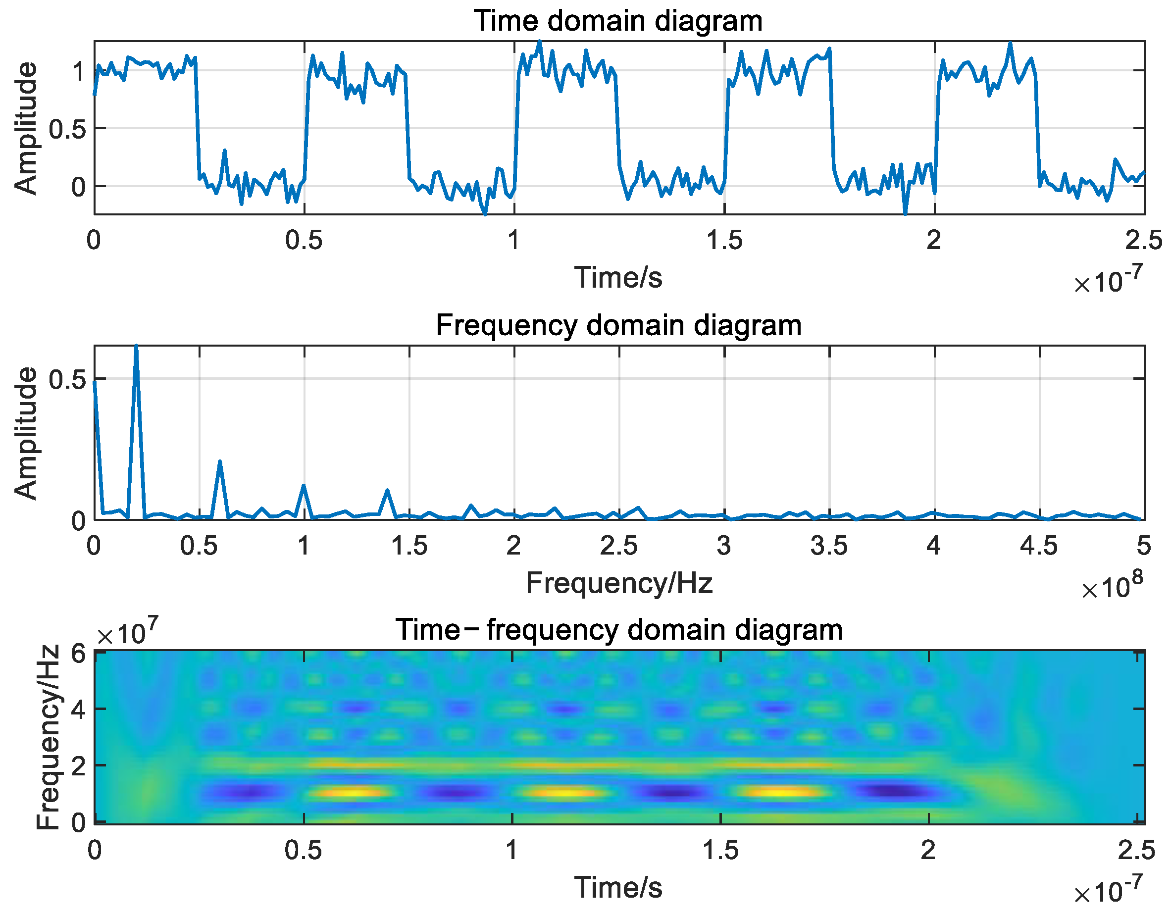
The time domain diagram, frequency domain diagram and time-frequency domain are shown in Figure 1.
As can be seen from Figure 1, the main feature of single-frequency jamming is that the energy is relatively concentrated. Therefore, single-frequency jamming has a good jamming effect on the signal near the frequency point. However, due to its narrow frequency band, it can be suppressed to the level of thermal noise through frequency filtering [12]. Navigation signals of different signal systems are affected by single-frequency jamming differently. The main research on single-frequency jamming is to select the optimal frequency point of jamming according to different signal systems [13]. Zhang [7] studied the optimal frequency point of single-frequency jamming of the newly added L1C signal in GPS III. Since the pilot channel of the L1C signal adopts the time-division multiplexed binary offset carrier (TMBOC) (6,1,4/33) modulation mode, the binary offset carrier (BOC) (6,1) modulation signal and TMBOC (6,1,4/33) modulation signal are simulated and analyzed. The results show that the optimal single-frequency jamming frequency of the BOC (6,1) modulation signal and TMBOC (6,1,4/33) signal is about 4750–4820 Hz away from the main lobe center in the offset range of −5000–5000 Hz, and the single-frequency jamming effect is basically consistent in this frequency range.
2
Pulse jamming
Pulse jamming mainly refers to the jamming signal composed of continuous ideal rectangular pulses. The general time domain waveform and frequency domain mathematical expression is as follows:
J ( t ) = A cos ( 2 π f c t ) s ( t ) s i ( t ) = 1 τ 2 + n T t τ 2 + n T , n = 1 , 2 0                          e l s e
S i ( f ) = + 2 sin ( n π τ T ) n δ ( f n T )
wherein, A is the amplitude of the pulse jamming signal, f c is the carrier frequency of the satellite navigation signal, s ( t ) is the ideal rectangular wave signal, τ is the pulse width, and T is the pulse period. The jamming frequency of pulse jamming is controlled by τ and the duty cycle of pulse jamming is controlled by τ and T .
The time domain diagram, frequency domain diagram and time-frequency domain of pulse jamming are shown in Figure 2.
As can be seen from the above figure, pulse jamming has small jamming bandwidth and high jamming efficiency. The jamming frequency band can be moved by controlling the pulse width and pulse period to achieve effective coverage of the desired signal frequency band and achieve an ideal jamming effect.
According to the power spectrum characteristics of different GPS signal systems, Mao et al. [14] set the frequency coverage of pulse jamming, simulated and analyzed the impact of suppression jamming on the GPS receiver code tracking error, and pointed out that under the same jamming signal ratio (JRS), the effect of pulse jamming is better than broadband Gaussian noise and matched spectrum jamming. Zhang [7] studied the efficiency of the pulse jamming signal on the L1C signal in GPS III. The simulation results show that the jamming effect of the pulse jamming with 4785 Hz offset from the main lobe center on the BOC (6,1) modulation signal, and the TMBOC (6,1,4/33) modulation signal is better than the pulse jamming at the main lobe center. In addition, the better the coverage of the navigation signal power spectrum, the better the effect of pulse jamming.
It can be seen that the optimal pulse jamming bandwidth and jamming frequency distribution range can be determined by analyzing the power spectrum characteristics of different navigation signal systems, so as to improve the jamming efficiency of jamming suppression.
3
Sweep jamming
Sweep jamming is also known as linear frequency modulation signal, which is similar to single-frequency jamming in form, but the carrier frequency of single-frequency jamming is fixed, while the carrier frequency of sweep frequency jamming changes with time. The general time domain waveform mathematical expression is as follows:
J ( t ) = A cos ( 2 π ( f c + f s w e e p t ) t )
wherein, A is the amplitude of the sweep jamming signal, f c is the carrier frequency of the satellite navigation signal, and f s w e e p is the sweep frequency.
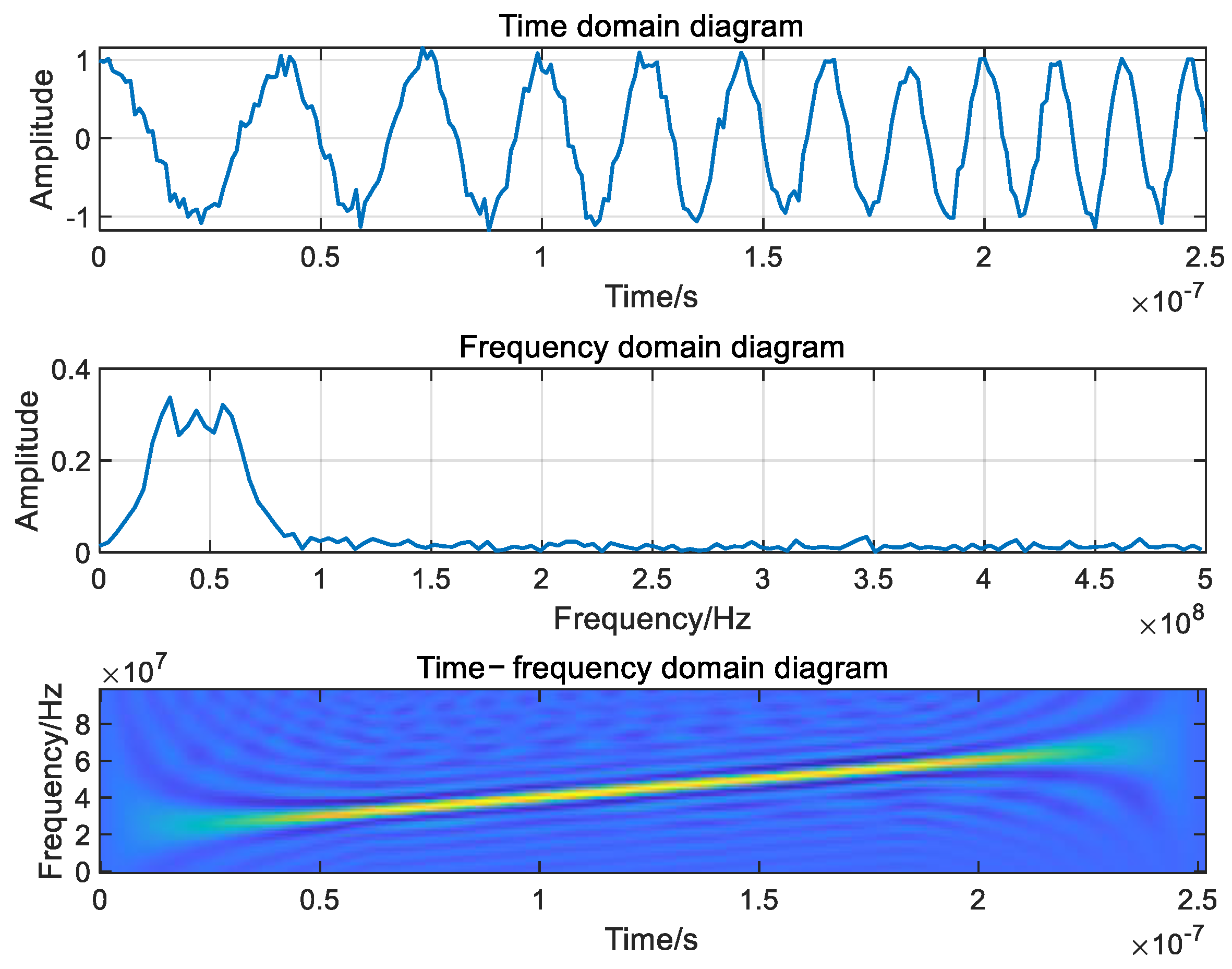
The time domain diagram, frequency domain diagram and time-frequency domain of sweep jamming are shown in Figure 3.
The sweep jamming can set the frequency sweep range according to the target navigation signal so that the target signal falls into the jamming spectrum range [15]. Secondly, sweep jamming has the characteristic of frequency mutation, which can cover a large swept frequency bandwidth in a short swept frequency period and reduce the suppression efficiency of the time-frequency domain anti-jamming algorithm [16,17,18].
4
Matched spectrum jamming
Combined with the characteristics of the satellite navigation signal, the matched spectrum jamming aims the jamming signal accurately at the navigation satellite downlink signal by introducing the navigation satellite signal spread code. Therefore, the specific format of the navigation satellite signal spread code must be obtained to generate the matched spectrum jamming, which is mainly used for civil code jamming. Because the matched spectrum jamming has the same power spectral density characteristics as the target navigation signal, it has a good jamming effect [19]. Taking the jamming signal of binary phase Shift Keying (BPSK) modulation mode as an example, the time-domain waveform expression is as follows:
J ( t ) = A cos ( 2 π f c t ) p ( t )
wherein A is the amplitude of jamming signal, f c is the carrier frequency of jamming signal, and p ( t ) is the pseudocode sequence of satellite navigation signal.
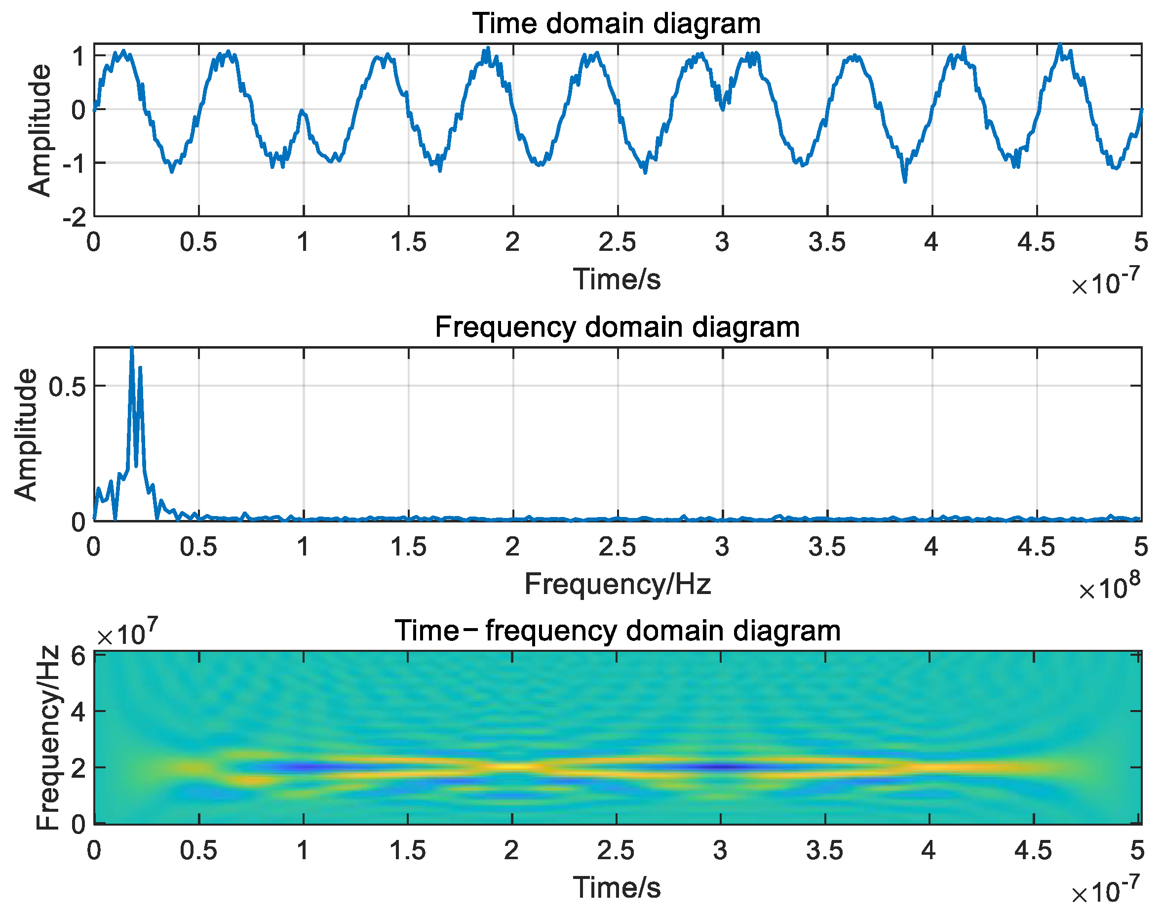
The time domain diagram, frequency domain diagram, and time–frequency domain of BPSK-modulated matched spectrum jamming are shown in Figure 4.
Wang et al. [20] pointed out that with the receiver error rate as the evaluation index, under the condition of the same jamming signal power, the effect of matched spectrum jamming is better than that of single-frequency jamming, white noise jamming and binary phase shift keying jamming.
In summary, the types of suppression jamming are relatively traditional and fixed, mainly including single-frequency jamming, pulse jamming, sweep jamming with relatively simple signal structures, and matched spectrum jamming that matches the spread spectrum code of satellite navigation signals. There are relatively few configurable parameters for suppressing jamming, which are usually used to test the effectiveness of satellite navigation anti-jamming algorithms, rather than conducting separate research as a subject.

2.1.2. Stability of Suppression Jamming

Suppression jamming can be divided into continuous and stable jamming and discontinuous and unstable jamming according to the stability of jamming. The spectrum characteristics of continuous and stable jamming change steadily or slowly, while the spectrum characteristics of discontinuous and unstable jamming change sharply.
The frequency point signal of GPS/Galileo L5/E5 shares the frequency band with some radio systems of the aviation radio navigation service (ARNS) and is often subject to jamming from multiple intermittent pulses generated by the pulse ranging equipment and tactical air navigation (TACAN) systems [21].
This distributed intermittent jamming is a common form of discontinuous and unstable jamming. The jamming characteristics generally show that the signal is incident from different directions, the spatial distribution is inconsistent, the time is discontinuous, and the single jamming presents the pulse jamming characteristics. Generally, it can be assumed that each jamming signal is a rectangular pulse-modulated signal, and its carrier frequency and signal bandwidth are basically consistent with the target navigation satellite signal. It is also assumed that the jamming signal is an ideal rectangular signal with a pulse rise time of 0 and a pulse decay time of 0. Then the mathematical expression of the time domain waveform is as follows:
J i ( t ) = A i b i ( t ) cos ( 2 π f c t ) s i ( t ) s i ( t ) = 1 τ 2 + n T t τ 2 + n T , n = 1 , 2 0                          e l s e
wherein, A i is the amplitude of the jamming signal, f c is the carrier frequency of the satellite navigation signal, s i ( t ) is the rectangular wave signal of the jamming signal, τ is the pulse width, and T is the pulse period. According to Fourier transform, it can be seen that:
rect ( τ ) τ s a ( π f τ ) = τ sin ( π f τ ) π f τ + δ ( t n T ) 1 T + δ ( f n T )
Therefore, the frequency spectra of s ( t ) and J ( t ) are as follows:
S ( f ) = + τ T sin ( π f τ ) π f τ δ ( f n T ) J ( f ) = B ( f ) P ( f ) = + τ T sin ( π f τ ) π f τ B ( f n T )
In space, the spatial distribution of each jamming relative to the receiver is relatively fixed, and the pitch angle and azimuth angle are expressed by θ and φ respectively. In terms of time, the arrival time of each jamming is random.
At present, antenna array anti-jamming technology is considered one of the most effective means of suppressing jamming in navigation receivers, which can effectively suppress multiple jamming. The research on antenna array anti-jamming technology is also developing and improving. In the face of continuous and stable jamming, antenna array anti-jamming technology has good anti-jamming efficiency. However, there are few studies on the influence of discontinuous and unstable jamming on the efficiency of navigation receivers. In the face of distributed intermittent jamming, the matching between the covariance of training samples and the covariance of actual processing signals will be a key factor affecting the anti-jamming performance. The signal to jamming plus noise ratio (SINR) loss L ( R x ) caused by sampling covariance mismatch is [22] as follows:
L ( R x ) = ( a s H R x 1 a s ) 2 a s H R x 1 R x R x 1 a s a s H R x 1 a s
where, a s is signal pilot vector; R x is real signal covariance matrix; R x is training sample covariance matrix. The SINR loss is determined by R x and R x . The length of training samples, jamming flicker period, and processing methods used in anti-jamming algorithms can all cause covariance mismatches and affect the anti-jamming effect. By controlling distributed intermittent jamming parameters, high SINR losses can be achieved, thereby achieving good jamming effects.
Wang et al. [23] pointed out that though the intermittent jamming power can be suppressed completely by the anti-jamming filter, the phase lock loop may lose lock due to channel scintillations. Li [24] believed that the least mean square (LMS) anti-jamming algorithm needs a period of weight convergence to adaptively form spatial nulls, while the distributed periodic intermittent jamming can slow down or even destroy the convergence speed of the adaptive zeroing algorithm, thus achieving a good jamming effect. In addition, the jamming efficiency of random intermittent jamming with an uncertain period is better than that of periodic intermittent jamming.
It can be seen that the stability of navigation jamming signals has a significant impact on the suppression performance of navigation receivers. Whether for SMI or LMS anti-jamming algorithms, in some scenarios, unstable and discontinuous jamming signals can seriously inhibit the suppression performance of receivers. Unstable and discontinuous jamming has many controllable parameters, and anti-jamming algorithms are difficult to deal with. It will become one of the mainstream research directions for suppression jamming in the future.

2.1.3. Bandwidth of Suppression Jamming

Suppression jamming can be divided into broadband jamming and narrowband jamming according to the classification of jamming bandwidth. The signal frequency bandwidth of narrowband jamming is generally far less than the target signal frequency bandwidth, and the autocorrelation is good. Although the target satellite navigation signal cannot be completely submerged, the energy is relatively concentrated, and the power spectral density is large, which can saturate or even overflow the navigation receiver channel; The signal frequency bandwidth of broadband jamming is generally equal to the target signal frequency bandwidth, and the spectrum amplitude is relatively flat, which can effectively partially or completely submerge the satellite signal, resulting in the navigation receiver being unable to capture the target satellite navigation signal and reducing the positioning efficiency of the navigation receiver [25,26].
Single-frequency jamming, multi-frequency jamming, sweep jamming and narrowband Gaussian jamming all belong to narrowband jamming. Pulse jamming, matched spectrum jamming, and broadband Gaussian jamming are all broadband jamming.
In addition, the selection of anti-jamming technology for satellite navigation antenna is usually related to the jamming bandwidth. Antenna anti-jamming technology can be divided into single antenna and antenna array anti-jamming technology according to the number of receiver antennas. Antenna array anti-jamming technology can use vector weighting to cancel jamming through multiple antenna elements. Therefore, the antenna array anti-jamming technology is not sensitive to the jamming bandwidth and can achieve the suppression of jamming with different bandwidths [27,28]; Single antenna anti-jamming technology will cause serious degradation of signal quality when suppressing broadband jamming, but single-antenna anti-jamming technology is the best choice when suppressing narrowband jamming [29,30,31].

2.2. Efficiency Evaluation of Suppression Jamming

The analysis of jamming suppression efficiency involves signal acquisition, pseudo-code tracking, carrier tracking, signal demodulation, pseudo-range measurement, and carrier phase measurement in the positioning efficiency of the navigation receiver, but it is difficult to measure and evaluate separately.
According to the working process of the tracking loop correlator, on the basis of approximating the power spectrum of the navigation signal to the envelope, Betz and Kolodziejski [32,33] deduced the analytical expression of the equivalent carrier-to-noise ratio of the receiver to express the jamming efficiency of the Gaussian band-limited jamming. Bek et al. [34] also derived the analytical formula of the equivalent carrier-to-noise ratio of single-frequency jamming, narrowband jamming, and broadband jamming through the formula. On the basis of reconsidering the power spectrum of the C/A code, Balaei et al. [35,36] deduced the equivalent carrier-to-noise ratio loss model of single-frequency jamming. Bek et al. [37] analysed the impact of pulse jamming on the carrier-to-noise ratio of the L1 frequency signal of GPS.
Mao et al. [14] pointed out that the tracking performance of pseudo-range code directly affects the acquisition of pseudo-range observation and determines the positioning accuracy and performance. Not only should the equivalent carrier-to-noise ratio be used as an evaluation index; the code tracking error should be used as an important index for jamming efficiency evaluation.
Taking code tracking error as the jamming efficiency evaluation index, Hu et al. [38] analysed the impact of frequency offset setting of single-frequency jamming on the anti-jamming efficiency of civil satellite navigation signals of different systems. On the basis of considering the influence of the pseudo-noise (PN)code discrete spectral line, Balaei et al. [35,36] deduced the analytical formula of maximum tracking error of single frequency jamming and the equivalent carrier-to-noise ratio. Zhang and Lohan [39] analysed the impact of narrowband jamming on the code-tracking accuracy of the E1 frequency signal of Galileo.
Wang et al. [5] took the power criterion, information criterion, probability criterion, and efficiency criterion as the jamming efficiency evaluation criteria, and, according to the different links of the navigation receiver signal processing, with the jamming-to-signal ratio and carrier-to-noise ratio as the basic indicators, built the suppression jamming efficiency evaluation system hierarchically. The jamming efficiency evaluation system is divided into navigation signal basic indicators and jamming efficiency evaluation indicators. Navigation signal basic indicators and jamming efficiency evaluation indicators are shown in Table 1 and Table 2.
It can be seen from the above tables that the efficiency evaluation indicators of suppression jamming include not only carrier-to-noise ratio, and pseudo-range tracking accuracy, but also acquisition probability, first acquisition time, error rate, and positioning accuracy.
In addition, Zhang et al. [40] demonstrated that the minimum jamming power when the GPS receiver cannot demodulate normally (when the carrier-to-noise ratio is equal to the tracking threshold of the receiver) as the jamming tolerance—which is used to characterize the anti-jamming efficiency of the signal—and used the jamming tolerance and jamming coverage to evaluate the jamming efficiency of the satellite navigation jamming signal on the GPS signal of the existing system.
Therefore, the jamming suppression efficiency is usually measured by the intermediate indicators at different levels of receiver signal processing, such as equivalent carrier-to-noise ratio, code tracking error, error rate, or the minimum jamming power when the receiver cannot work. However, the current literature usually only selects one or several indicators to evaluate the suppression jamming efficiency and does not establish a complete evaluation system. In addition, there is no literature on suppressing jamming efficiency evaluation for all satellite navigation systems.

2.3. Jamming Source Deployment of Suppression Jamming

Although adaptive beamforming technology is one of the most effective means to improve the jamming tolerance of the receiver, only when the number of jamming sources is less than the number of antenna arrays can it achieve a good anti-jamming effect [41]. If we try to ensure that the number of jamming sources is greater than or equal to the number of antenna array elements, and the layout is reasonable, the effect of adaptive zeroing technology will be invalid. Therefore, the deployment of multiple jamming sources is an effective means to achieve good jamming suppression, counter adaptive zeroing and beamforming technology. Moreover, most jamming targets, such as precision-guided weapons, are in motion or high-speed motion, and the jamming source has limited mobility, so it is necessary to deploy the moving range of the jamming target in advance. The deployment effect of the jamming source will directly affect the jamming power distribution in the jamming area and ultimately affect the jamming effect.
While most jamming targets such as precision-guided weapons use the combined navigation form of satellite navigation and inertial navigation. When the satellite navigation receiver loses its lock and stops working, the navigation error is determined by the inertial navigation error.
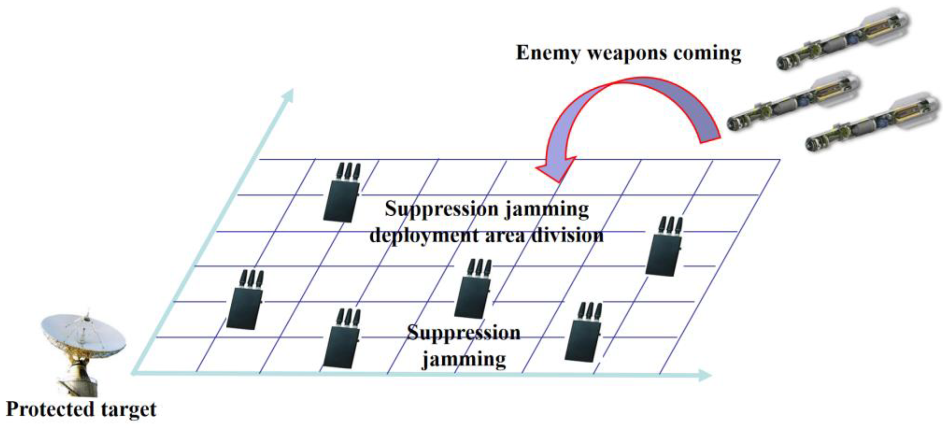
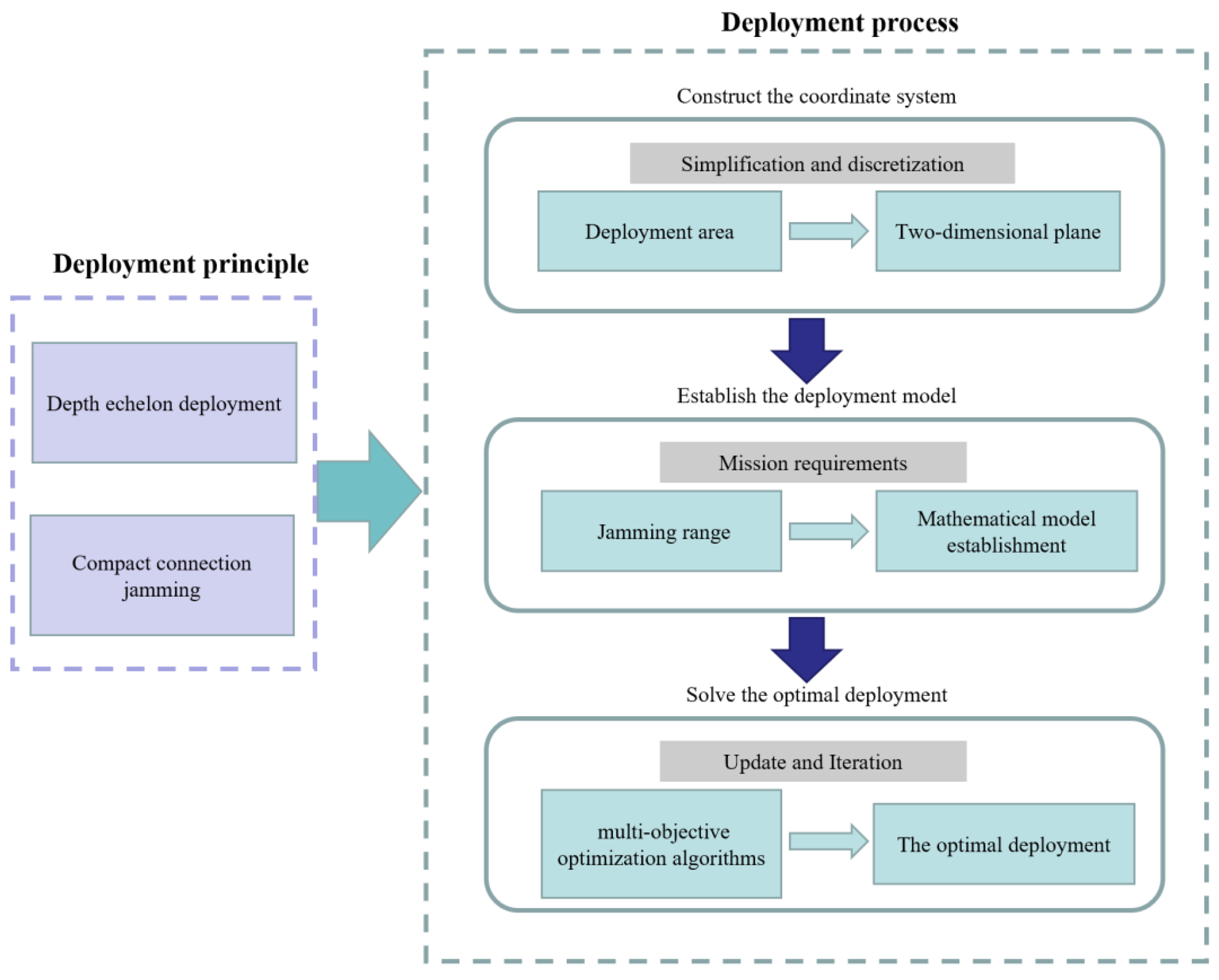
Cheng et al. [42] pointed out that the deployment of satellite navigation jamming sources should follow the two principles of depth echelon deployment and compact connection jamming. First of all, the chain configuration mode is adopted for jamming relay in the direction of jamming target movement. Secondly, efforts should be made to reduce the occurrence of jamming “gap” to avoid restarting the positioning function of the satellite navigation receiver to correct the inertial navigation error that has been introduced. The closer the jamming “gap” is to the target, the higher the threat to the target. The schematic diagram of suppression jamming deployment is shown in Figure 5.
In a designated area, optimizing the deployment of suppression jamming sources usually involves several steps:
  • Construct the coordinate system of suppression jamming deployment area: generally, the deployment area is simplified to a two-dimensional plane and discretized to facilitate labeling and calculating the location and area of the jamming sources;
  • Establish a multi-objective optimization deployment model (based on mission requirements, it is usually based on the jamming range);
  • Solve the optimal deployment of suppression jamming: iterative calculation using multi-objective optimization algorithms such as genetic algorithm and ant colony algorithm.
The flowchart of suppression jamming deployment is shown in Figure 6.
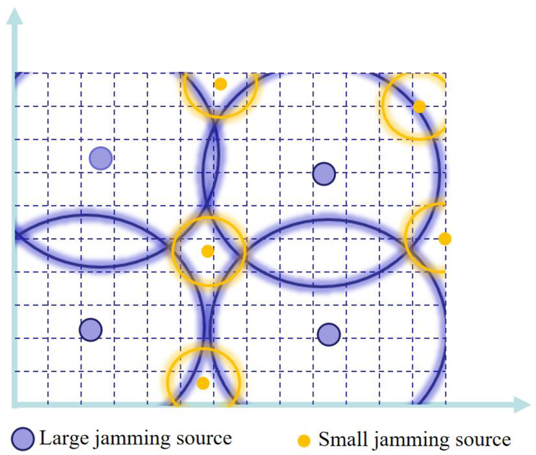
It is assumed that the jamming sources mainly include four large jamming sources with relatively large jamming ranges and five small jamming sources with relatively small jamming ranges, and all jamming sources can interfere omnidirectionally. In a two-dimensional planar scene, based on the set deployment optimization model, the optimal deployment plan can be calculated through multiple iterations of optimization algorithms such as genetic algorithms. The effect diagram of optimized deployment of suppression jamming is shown in Figure 7.
In the literature [43,44,45], the genetic algorithm is used to solve the problem of maximum coverage of the target area via the minimum number of suppression jamming sources. Yan et al. [46] pointed out that the jamming sources of the above methods did not achieve coordination, and the utilization rate was not high. Based on this, a networked air jamming source deployment model is established. The main beam direction of jamming signals is aligned with the moving target. The jamming source deployment is carried out by using the genetic algorithm to optimize the deployment of jamming sources based on the principle of maximizing the minimum jamming power in the target area. Fu et al. [47] believed that it is not comprehensive to only consider the size of jamming power. It should also include the threat degree of the enemy weapon platform to our important targets. When jamming the enemy’s weapon platform fails, the farther it is from our important target, the smaller the threat to our side. Then the jamming source deployment model is established and solved by the genetic algorithm. Cheng et al. [42] took regional coverage and average risk index as evaluation indicators and uses the genetic algorithm to solve the optimal deployment of multi-objective jamming sources. The area coverage rate is defined as the ratio of the effective suppression area of the jamming source to the total area, and the average danger index is used to describe the threat degree of the protected target.
In summary, the current research on optimal deployment of suppression jamming sources is still at the stage of theoretical derivation and simulation verification, mainly based on the distance of suppression jamming (suppressing jamming power), and based on multiple deployment principles such as coverage, a geometric deployment model of jamming sources is constructed, and finally solved using optimization algorithms such as genetic algorithms. However, the current research on optimal deployment of suppressed jamming sources is basically simplified to a geometric coverage problem, usually only changing the deployment criteria. In essence, it is to solve the physical geometric area and coverage multiplicity, but less consideration is given to the signal characteristics of suppression jamming itself.

3. Deception Jamming

Deception jamming is a satellite navigation jamming technology. The deception jamming source generates the deception signal similar to the real satellite navigation signal in the signal system and spectrum structure, but with a power slightly higher than the real signal, or else it repeats the real satellite navigation signal in space. Through the deception algorithm, the receiver mistakes the deception signal for the real satellite navigation signal for acquisition, tracking, and positioning solution, which ultimately results in the receiver outputting the wrong time and space information [48]. The main features of deception jamming include good anti-jamming performance, high concealment, and being difficult to be detected by the receiver. It can accurately control the preset wrong space–time information output by the receiver. However, the jamming technology involved in deception jamming is relatively complex, and the jamming range is relatively narrow, i.e., generally only for specific users.

3.1. Classification of Deception Jamming

There are many types of deception jamming, which can be classified according to the generation mode, implementation stage, and implementation difficulty of deception jamming.

3.1.1. Generation Mode of Deception Jamming

Deception jamming can be divided into generated deception jamming and repeater deception jamming according to the generation mode.
  • Generated deception jamming
The generated deception jamming mainly refers to the jamming method that generates and independently transmits the deception signal with the same structure as the real navigation signal according to the disclosed civil satellite navigation signal structure simulation. Gradually, it replaces the real signal into the tracking loop by virtue of the signal control strategy and power advantage; then, it controls the tracking loop to achieve the purpose of deception [49].
The generated deception jamming can control various parameters independently, with high flexibility and strong concealment. However, the generated deception jamming needs to obtain the structure of the navigation signal in advance, and the structure of the military navigation signal is unknown and difficult to crack. Therefore, it is impossible to implement generated deception jamming against military code signals, and the scope of use has certain limitations. The key to affecting the effect of generated deception jamming is the quality of deception signal generation. Only by keeping the same signal parameters and signal synchronization with the real satellite signal can the satellite navigation receivers receive the deception signal and determine it as the real satellite navigation signal, implementing the deception.
Signal synchronization mainly refers to the estimation of the signal power, code phase, doppler frequency shift, and other parameters of the real signal received by the target receiver to make the deception signal align with the parameters of the real signal when reaching the target receiver. Signal synchronization is the basis of generated deception jamming [50,51]. He et al. [52] discussed the ranging error and ionospheric delay and their impact on signal synchronization, the influence of ranging error and ionospheric delay on signal synchronization, and the ranging accuracy required to achieve signal synchronization. In the literature [53], the calculation methods of the important parameters required by the generated deception jamming, such as the signal transmission power, doppler frequency, and code phase, were given in the synchronous and asynchronous phase of the signal.
2
Repeater deception jamming
Repeater deception jamming mainly refers to the jamming method that adds a certain time delay on the basis of receiving the real satellite navigation signal and repeats the signal through power adjustment to make the satellite navigation receiver receive the repeater signal, thus implementing deception [54,55].
Repeater deception jamming is easy to operate and does not need to obtain the satellite navigation signal structure in order to jam the military code. However, repeater deception jamming is easily recognized by the receiver as multipath jamming and processed; hence, the success of deception is not high. If repeater deception jamming directly repeats the received satellite signal to the target receiver without considering the actual position and speed of the target receiver, it leads to a large deviation between the deception position and the target position and thus to deception failure [56]. Therefore, one of the key steps of repeater deception jamming is to separate and purify the received signal, combine the position and speed information of the target receiver, and calculate and control the repeater delay. By analyzing the working principle of repeater deception jamming, Zhen et al. [57] proposed a method by which to calculate the channel delay and determine the maximum range of forward delay. In addition, repeater delay control is generally achieved through the reasonable layout of single-station or multi-station repeater deception jamming sources.
The generated deception jamming and repeater deception jamming are summarized in Table 3.

3.1.2. Implementation Stage of Deception Jamming

Satellite navigation signal processing mainly includes signal down-conversion, signal acquisition, and signal tracking. Generally, the implementation phase of deception jamming is usually during the phase of signal acquisition and signal tracking.
  • Signal acquisition stage
In the actual deception scenario, the method of suppression jamming is usually used first to force the satellite navigation receiver to lose the lock state. In the process of reacquisition, the deception signal with higher power can generate a higher power correlation peak in the two-dimensional search space composed of doppler frequency and code phase and is locked into the acquisition and tracking state by the receiver [58,59,60].
However, due to the existence of high-power deception signals, the noise base of the receiver will rise, and the real satellite navigation signals will be interfered with or even submerged in the deception signals [61]. The obvious change of receiver environment caused by the high-power deception signal also has the possibility of being detected by the receiver [62].
The complex model of real signals and deception signals can be expressed as [62] follows:
r ( n T ) = P t M t ( n T τ t ) C t ( n T τ t ) e j ( φ t + 2 π f t n T ) + P d M d ( n T τ d ) C d ( n T τ d ) e j ( φ t + 2 π f d n T ) + η ( n T )
wherein, T is sampling interval, n is number of samples, t , d represent real signals and deceptive signals, respectively, r is the complex signal, P is signal power, M is satellite navigation message, C is spread spectrum code, φ is carrier phase, f is doppler frequency, τ is the code phase, and η is Gaussian white noise with a mean value of 0 and a variance of σ η 2 .
The next step it to perform correlation integration between the composite signal and the spread spectrum code that is not in the signal by which to estimate the noise base. The correlation integration expression can be expressed as [62] follows:
C I f l , τ l , k = 1 N n = ( k 1 ) N + 1 k N r ( n T ) C l ( n T τ l ) e 2 π f l n T
δ 2 = 1 2 N k = 0 N 1 C I f l , τ l , k 2 = 1 2 D ( C I f l , τ l , k ) = 1 2 D ( P t ψ t l f l , τ l , k ) + D ( P d ψ d l f l , τ l , k ) + η ( N [ k ] )
ψ t l f l , τ l , k ~ N 0 0 , σ ψ 2 0 0 σ ψ 2
ψ d l f l , τ l , k ~ N 0 0 , σ ψ 2 0 0 σ ψ 2
η [ k ] ~ N 0 0 , σ η 2 N 1 0 0 1
wherein, C I is coherent integration, D is variance, l is local signal, k is Integral interval, ψ t l f l , τ l , k , ψ d l f l , τ l , k represent the relevant parameter of real signal and local signal and the relevant parameter of deception signal and local signal, and the I-branch and Q-branch of ψ t l f l , τ l , k , ψ d l f l , τ l , k , η [ k ] obey a zero mean Gaussian normal distribution.
Therefore, the correlated interference generated by the deception signal will seriously affect the noise base estimation. The power control and deception strategy of the deception signal are crucial to the deception effect of the receiver in the acquisition stage.
Some scholars have conducted research on the power control problem when deception jamming sources deceive receivers at the acquisition stage. Pang et al. [63] pointed out that when the receiver is in the reacquisition stage, the power of the deception signal only needs to be greater than the power of the real satellite signal to be captured by the receiver and implement deception. When the receiver is in the acquisition phase, it is necessary to increase the power of the deception signal to force the receiver without anti-deception technology to capture and track it. Wang et al. [64] compared and analyzed the deception effects of direct intrusion and suppression jamming assistance on the receiver acquisition and tracking loop. The simulation results showed that the suppression jamming assistance method was superior to the direct intrusion method. The direct intrusion method can only make the receiver locate incorrectly, while the suppression jamming assistance method can deceive the receiver to the predetermined position. According to the acquisition principle of the satellite navigation receiver, Liu et al. [65] deduced the acquisition probability of repeater deception jamming. Through simulation analysis, it is pointed out that the transmitting gain of the deception jamming signal only needs to be 7–10 dB, and the receiver can achieve effective acquisition of the deception signal. Tippenhauer et al. [66] pointed out that when the power of the deception signal is more than 2 dB higher than the real signal, the receiver can always lock on the deception signal without any offset. Ma et al. [67] theoretically calculated the relationship curve between the probability of the receiver capturing the deception jamming signal and the jamming signal ratio. When the jamming-to-signal ratio is greater than 5 dB, it can basically ensure that the receiver captures the deception signal in the acquisition phase.
After successfully deceiving a receiver in the acquisition stage, subsequent deception strategies also affect the deception effect. Hu et al. [68] conducted the simulation experiment of deception jamming power control. The simulation results showed that in order to ensure the continuous traction of the deception signal on the receiver acquisition loop, the noise base and the maximum signal-to-noise ratio of the deception signal could be limited to 3 dB and 22 dB by adjusting the deception power in real-time. Sheng et al. [53] pointed out that when the deception signal is captured by the receiver through the power advantage, the code rate should be gradually increased so that the phase of the deception signal number is more than two chips from the phase of the real signal number to ensure that the receiver can track the deception signal stably.
At the same time, using high power deception signals to force the receiver in the tracking state to lose lock, and then implementing deception is also a deception method. Pang et al. [63,69] pointed out that when the delay time of the repeater deception jamming is greater than one chip of the real signal, there is almost no mutual jamming between the deception signal and the real signal, and the deception jamming effect is basically equivalent to the broadband jamming of the suppression jamming. Lv et al. [70] analyzed the influence of the repeater deception jamming ratio on the tracking status of the receiver. The results showed that when the jamming signal ratio reached 25 dB, the deception signal destroyed the tracking state of the receiver and forced the receiver to reacquire the tracking deception signal in the signal tracking stage.
In addition, Andrew et al. [71] pointed out that if the deception intention is not concealed, as long as the power of the deception interference source reaches and exceeds the receiver acquisition detection threshold, the deception jamming source can successfully control the receiver’s acquisition and tracking loop, but this method will inevitably trigger the receiver’s deception detection measures. Through theoretical derivation of the deception mechanism of the deception signal, Lv et al. [70] analyzed the impact of deception jamming on the receiver’s acquisition performance and pointed out that when the deception signal and the real satellite signal differ by 1.5 chips, there will be two correlation peaks that will be detected by the receiver. Therefore, the deception signal should also avoid being detected by the anti-deception algorithm when attacking the receiver in the acquisition state.
To sum up, it is a simple and effective deception method to implement suppression jamming or high-power deception jamming on the target receiver without considering deception detection processing, forcing the receiver to lose lock and enter the reacquisition state. However, currently, receivers are gradually deploying deception detection devices, and deception power control and deception strategies under deception detection conditions will be the focus of the receiver during the deception signal acquisition stage.
2
Signal tracking stage
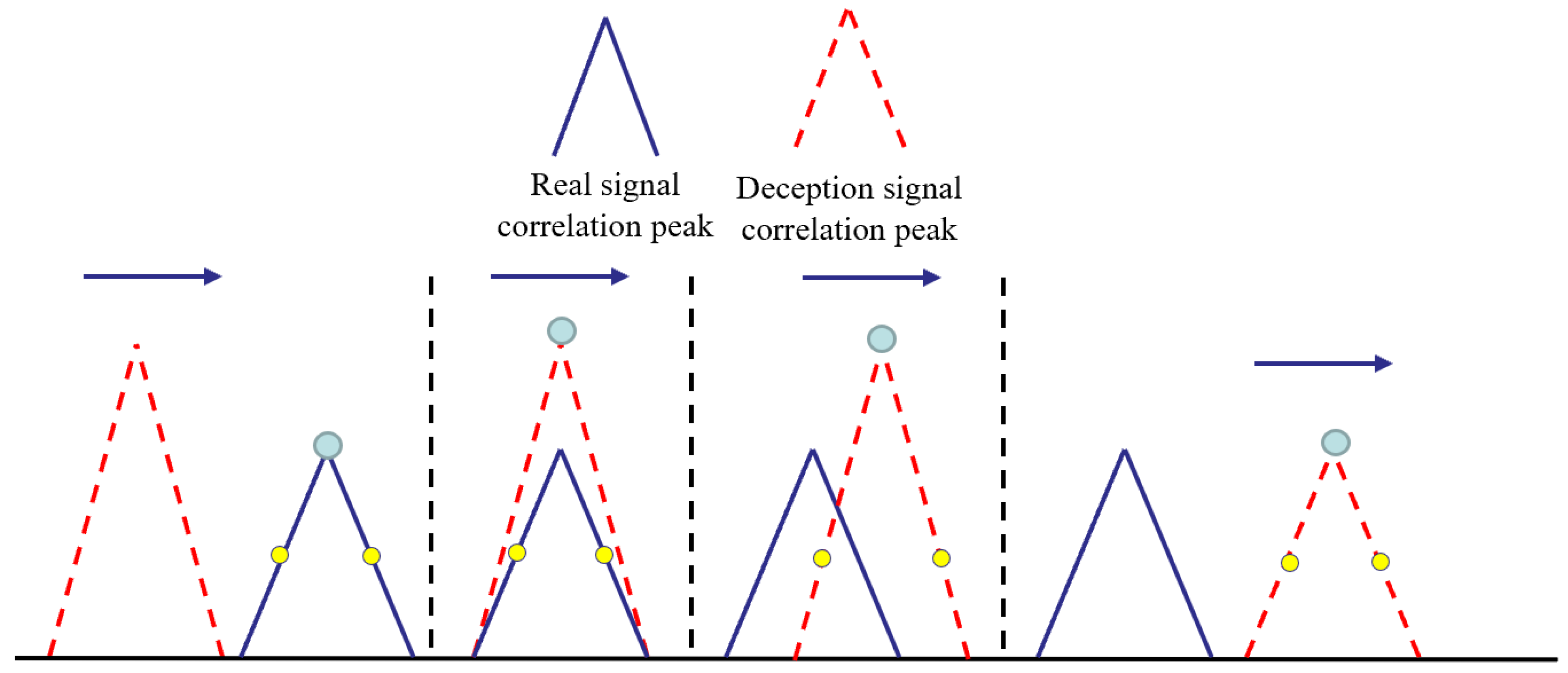
Using a high-power deception signal to force the receiver into the tracking state also has the problem that the detected signal is abnormal and leads to deception failure. Therefore, the deception jamming on the receiver in the tracking stage is more covert, but the technical requirements are also higher [72,73]. Usually, traction deception technology is used [74]. On the basis of the similar power of the deception signal and the real signal, researchers have adjusted the phase of the deception signal number and realized the traction of the tracking loop by sliding relative to the phase of the real satellite navigation signal number so as to avoid the lock loss of the receiver caused by the high-power signal, thus realizing their covert deception [75,76,77]. The schematic diagram of the traction jamming implementation process is shown in Figure 8.
Traction signal deception methods are mainly divided into two categories: the first method requires maintaining a proportional relationship between the doppler frequency of the deception signal and the doppler frequency of the spread spectrum code; the second method requires the deception signal to maintain the carrier frequency of the deception signal equal to the carrier frequency of the real signal while improving the code rate. The two methods each have advantages and disadvantages. The first method may be detected as abnormal due to changes in the carrier frequency difference between the real signal and the deception signal. As to the second method, although the carrier frequency of the deception signal in the second method is consistent with the carrier frequency of the real signal, the inconsistency between the doppler frequency of the deception signal and the doppler frequency of the spread spectrum code also poses a risk of being detected [78].
Todd et al. [49] developed the first truly GNSS progressive traction deception jamming source. Daniel et al. [58] pointed out that in order to achieve effective deception, the deception signal will split the true code phase of the receiver in the tracking stage by more than two chips. Huang et al. [79] established a receiver–tracking model and quantitatively analyzed the influence of deception signal power on the traction effect of the target receiver–tracking loop. The deception signal power only needs to be 4 dB higher than the real signal power, which can destroy the typical receiver’s tracking of the real signal in 50 min and make it track the deception signal instead.
Kerns et al. [71] pointed out that when implementing covert deception on receivers in tracking status, the deception signal should not be too high and should be strictly controlled, and the maximum Doppler frequency shift should also be controlled within 50 Hz to ensure that the deception signal frequency is consistent with the true signal frequency as much as possible. Ma et al. [67] pointed out that when the receiver is in a stable tracking state, the local code phase is precisely synchronized with the real signal phase. Only when the difference between the deception signal and the local signal is less than one code phase, can the deception signal use the power advantage to pull the receiver to bias and successfully implement deception. He et al. [52] analyzed and discussed the power conditions of deception jamming and pointed out that in order to avoid being detected by the detection algorithm, the increased rate of deception jamming power should not be too large. When the correlation peak of the deception signal is slightly greater than the correlation peak of the real signal, the real signal can be stripped of the receiver–tracking loop. In order to enable the deception signal to directly peel off the real signal and enter the receiver–tracking loop, Sheng et al. [53] proposed an asynchronous attack strategy: first, generate a high-power lag correlation peak; then, speed up the deception signal number rate, so that the deception signal number phase is aligned with the real signal code phase and ahead of the real signal number phase. The target receiver will gradually peel off the real signal and continue to track the deception signal. Li et al. [80] built a Beidou navigation receiver deception jamming test platform to test the influence of deception jamming under different power conditions on the Beidou navigation receiver in a stable tracking state. The test results showed that when the deception signal power reached 25 dB, a certain type of Beidou navigation receiver loss its lock and captured the deception signal again.
To sum up, whether in the signal acquisition stage or the signal tracking stage, the control strategy of the deception signal is one of the key factors affecting the deception efficiency. For receivers at different stages, different deception power control methods need to be used to implement deception. However, the current research on deception power control mostly stays in the stage of theoretical model establishment and actual measurement simulation for some typical receivers; deceptive signal power control methods have not yet formed a systematic experimental and theoretical control strategy. Secondly, the experimental environment and theoretical assumptions of deception jamming are too idealistic, and the detection methods for deception jamming are endless. Using the deception signal power control strategy obtained under the idealistic conditions and the deception signal power for some typical receivers to cheat, it is likely to lead to deception failure. Finally, although traction deception is currently a research hotspot in the field of satellite navigation deception and jamming, the limitations of knowing the accurate code information, frequency information, and location information of the target receiver still limit the scope of use of this traction jamming.
The comparison of deception methods with different implementation stages are summarized in Table 4.

3.1.3. Implementation Difficulty of Deception Jamming

Generated deception jamming can be divided into primary, intermediate, and advanced navigation deception jamming technologies according to the implementation difficulty [81,82].
  • Primary navigation deception jamming
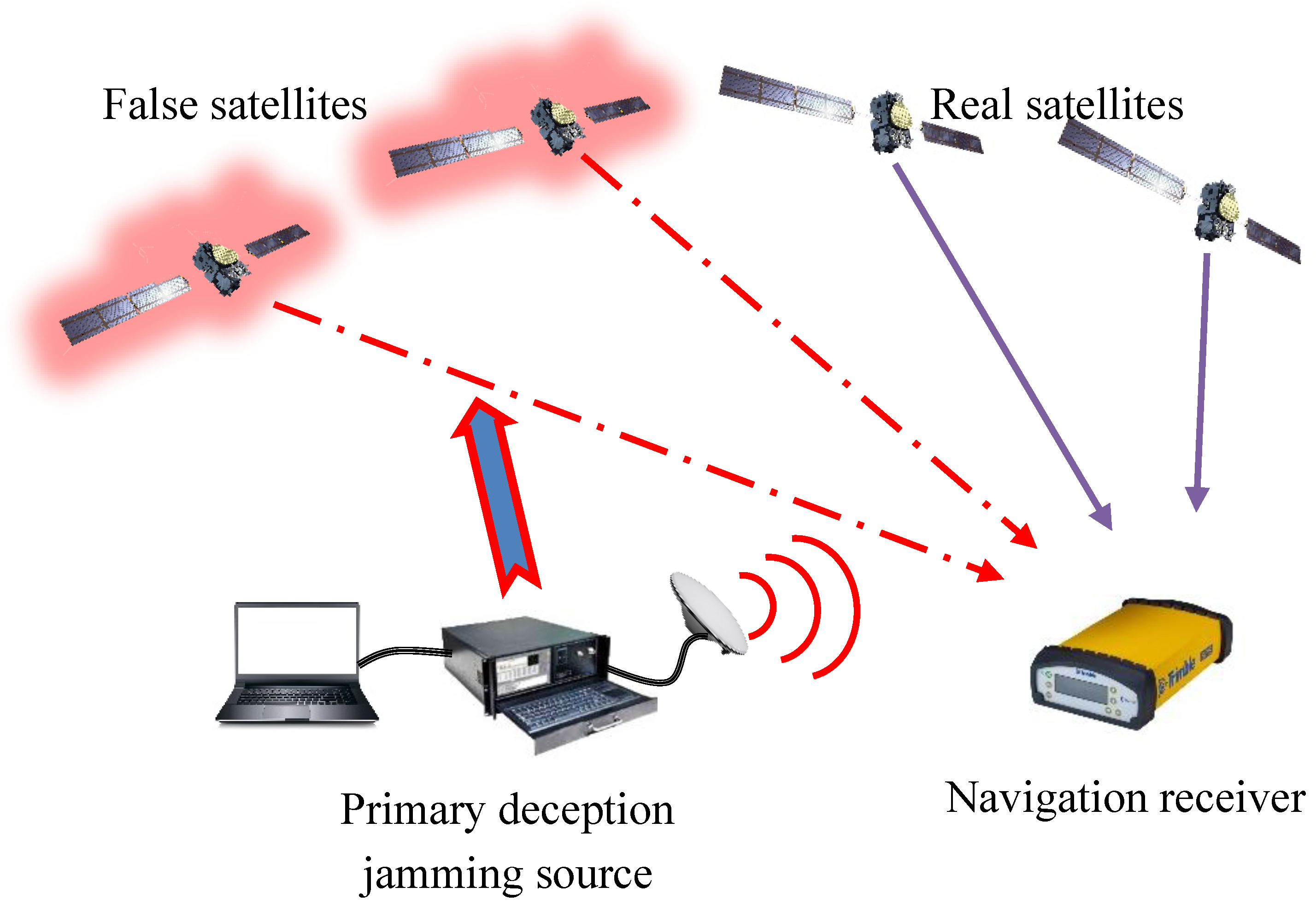
Primary navigation deception jamming, also known as satellite navigation simulator deception technology, is the simplest generation deception technology, mainly composed of the satellite navigation signal simulator, signal amplifier, and transmission antenna. The deception signal generated by the simulator is difficult to keep synchronized with the real satellite navigation signal, and the correlation peak cannot be aligned. The primary method is to force the receiver to recapture and track the deception signal by increasing the power of the deception signal so as to achieve deception jamming. The schematic diagram of primary navigation deception jamming is shown in Figure 9.
2
Intermediate navigation deception jamming
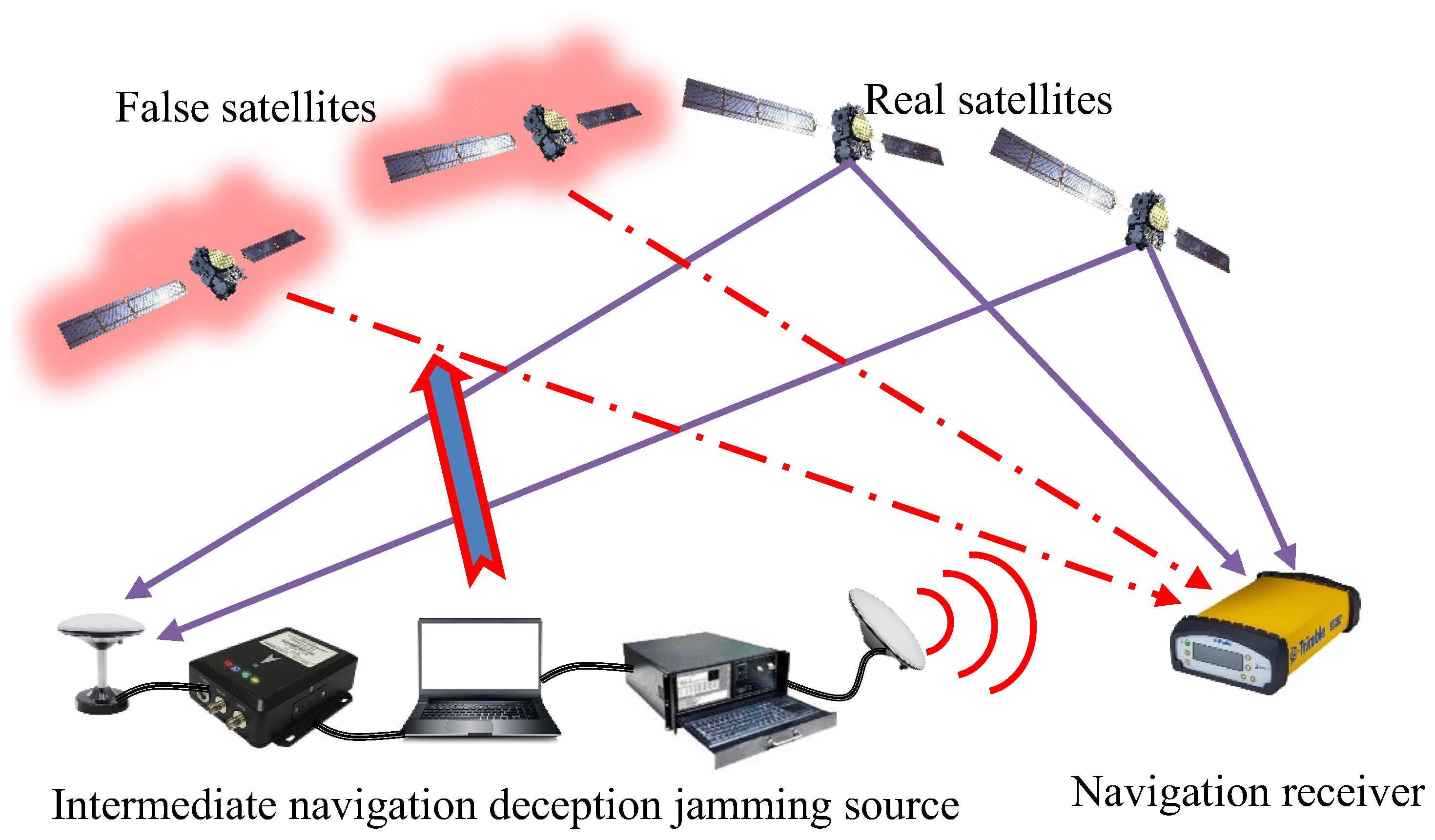
Intermediate navigation deception jamming technology is more complex than primary navigation deception technology; it not only needs to receive the real satellite navigation signal but also needs to keep the signal synchronized. Therefore, the mode of “receiving navigation signal–generating navigation signal–transmitting deception signal” is adopted to implement deception. First, the real satellite navigation signal is received for acquisition and tracking, and the position and speed status information of the target receiver is obtained through external auxiliary equipment, and the relative time delay is calculated. From this, a deception signal synchronized with the real navigation signal received by the target receiver is constructed. With the help of power advantage, the real signal is gradually replaced and entered into the tracking loop to implement deception. The intermediate navigation deception technology also does not need to obtain the real navigation signal structure and can cheat the military code signal. In addition, the deception signal is basically synchronized with the real navigation signal, which is difficult to detect via the receiver and has good concealment. However, it needs to involve more complex models in order to obtain the target receiver status information and maintain the correct signal delay and appropriate transmission power. At present, the intermediate navigation deception technology still struggles to achieve senseless deception, and the target receiver channel can be sensitive to the change of the received signal for deception detection. The schematic diagram of intermediate navigation deception jamming is shown in Figure 10.
3
Advanced navigation deception jamming
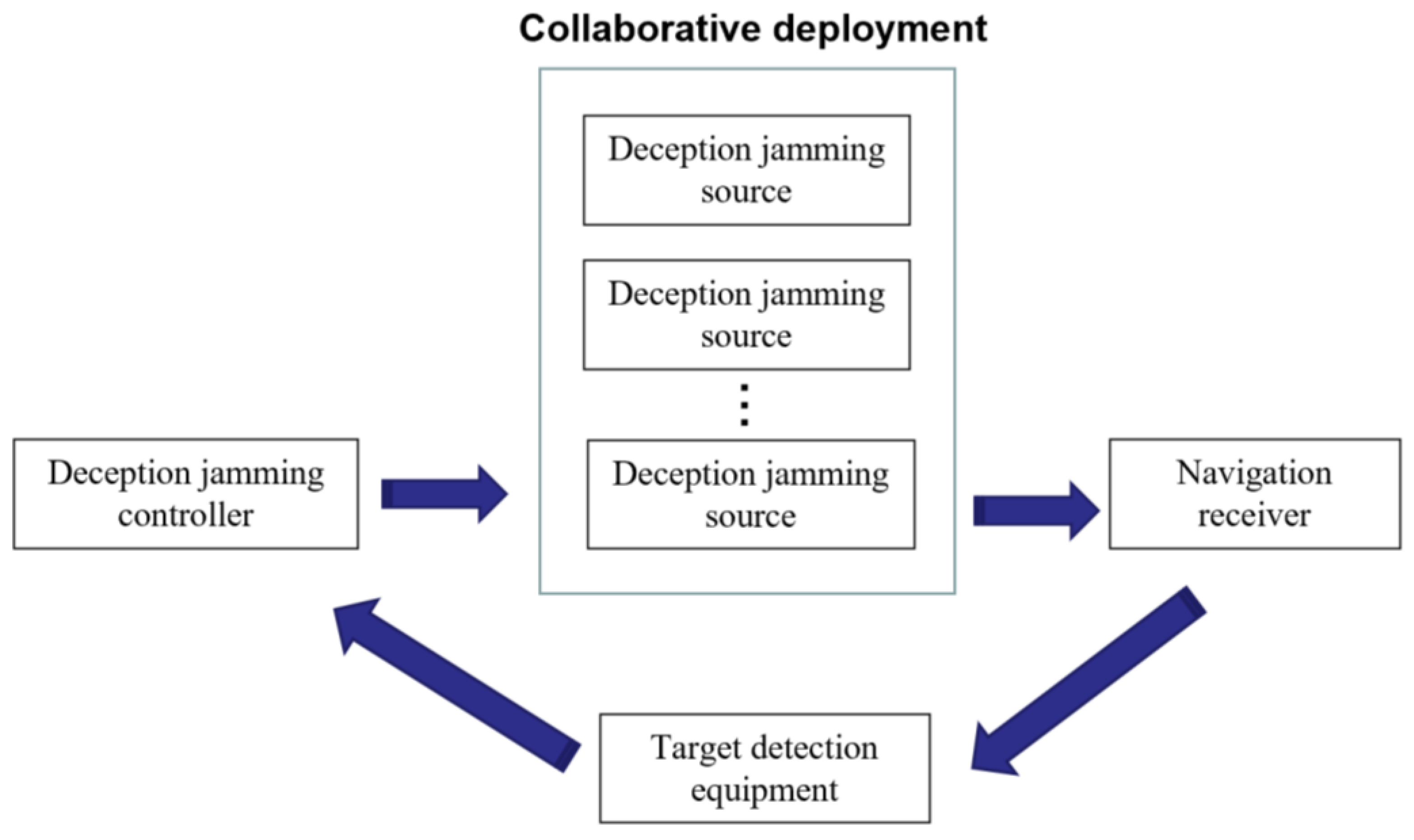
Advanced navigation deception technology is currently the most complex but effective deception method. It mainly uses multiple intermediate deception jamming systems to implement deception by simulating real reception scenarios through distributed cooperative work. The detection equipment is used to detect the target, and the control command is generated according to the detected target position and certain control strategy. Therefore, the deception signal not only keeps synchronization with the real navigation signal but also keeps synchronization between the deception signals to simulate the most real satellite distribution environment, which makes the anti-deception jamming technology based on detecting the direction of signal arrival ineffective. However, due to the limitations of array manifold synchronization and other technologies, this deception technology can only be implemented in a small range near the target receiver. Once the target receiver moves, it is difficult to implement deception. Therefore, the advanced navigation deception technology is still at the theoretical research level, but once the technical breakthrough is achieved, it will become the most effective deception jamming method. The schematic diagram of advanced navigation deception jamming is shown in Figure 11.
The comparison of different deception methods in terms of deception effect, scope and cost is shown in Table 5.
To sum up, although the primary navigation deception jamming technology is simple and the cost is relatively low, it easily detected by a variety of deception detection methods. As the mainstream generation jamming method, intermediate navigation deception jamming has a good jamming effect. However, it is also troubled by the difficulty in controlling the synchronization accuracy of the generated deception jamming signal, which limits the improvement of the deception jamming efficiency. Advanced navigation deception jamming theory is the best, but the cost is very high, and it requires many factors such as target location, jamming source deployment, etc. Therefore, it is still at the level of theoretical simulation.

3.2. Efficiency Evaluation of Deception Jamming

The efficiency analysis of deception jamming also involves signal acquisition, Pseudo-code tracking, position calculation, and other links in the positioning performance of the navigation receiver.
According to the GPS acquisition principle, Liu et al. [65] simulated and analyzed the carrier-to-noise ratio of the GPS receiver and the acquisition probability curve of the repeater deception jamming signal to evaluate the efficiency of the transmitted deception jamming, but only around the receiver acquisition level; the evaluation index is not comprehensive.
Ail et al. [62] analyzed the influence of the deception signal on the carrier-to-noise ratio estimation of the GPS receiver in the acquisition phase and pointed out that the deception signal can effectively interfere with the receiver correlation peak and increase the noise base. On the basis of deducing the relationship between the acquisition probability and the jamming-to-signal ratio of the repeater deception jamming, Zhang et al. [83] calculated the effective jamming distance of repeater deception jamming to evaluate the jamming efficiency. Liu [84] analyzed the changes in the code loop of the satellite navigation receiver in the process of tracking the deception signal. Kim et al. [54] simulated and analyzed the influence of the chip delay of the deception signal on the code tracking error, frequency tracking error and pseudo-range nonlinear change of the receiver.
Wang et al. [5] also pointed out that the evaluation index of the deception jamming effect should include deception probability, positioning accuracy, and jamming onset time while systematically constructing the evaluation system of the suppression jamming effect. Zhen [85] used the evaluation of deception probability, positioning accuracy deterioration factor, and anti-jamming quality factor to evaluate the efficiency of deception jamming.
Based on the principle of deception jamming technology, according to the different levels and links of satellite navigation signal processing, Wang et al. [86] built the effectiveness evaluation system of deceptive jamming with the navigation signal, positioning results, and software and hardware performance as the entry point. It is also pointed out that various indicators related to navigation signals are the most intuitive reflection of the effect of deception jamming, and the positioning result is an important level to reflect the effect of jamming.
In addition, on the basis of several GNSS deception jamming efficiency evaluation indicators, in order to improve the evaluation efficiency, Wang [87] optimized the deception jamming efficiency evaluation index system, proposed the deception jamming efficiency evaluation method based on grey relational analysis (GRA) and fuzzy comprehensive assessment(FCA) to enhance the impact of high correlation indicators on the deception jamming efficiency evaluation results, and proposed the deception jamming efficiency evaluation index based on cloud model to reduce the impact of ambiguity and randomness.

3.3. Jamming Source Deployment of Deception Jamming

There are few studies on the optimal deployment methods of deception jamming sources, but it is still a necessary and important part of deception jamming research.
The research on the deployment of repeater deception jamming sources mainly focuses on how to obtain a good mapping relationship between the target real location (real point) and the target deception location (virtual point) and a reasonable repeater delay by reasonably deploying the jamming source location so as to achieve a good deception effect and expand the deception range.
Starting from the principle of satellite navigation and positioning, Yang et al. [88] proved that there is a mapping relationship between the real point and the virtual point and that it is physically realizable.
According to the number of repeater jamming sources, it can be divided into single-station and multi-station repeater jamming source deployments.
Single-station repeater deception jamming has the advantages of simple equipment and a large effective jamming range, but the location of jamming sources is relatively harsh. Zhang et al. [89] established a single-station repeater area mapping model and pointed out that when transmitting four satellite signals, the jamming source can realize deception jamming if it is located at the intersection of the single curved surface formed by the four satellites being transmitted. Based on the single-station forwarding area mapping model, Zhen et al. [90] analyzed the impact of different initial delays on the height and range of jamming sources, and then proposed a single-station repeater jamming source deployment method based on the initial delay.
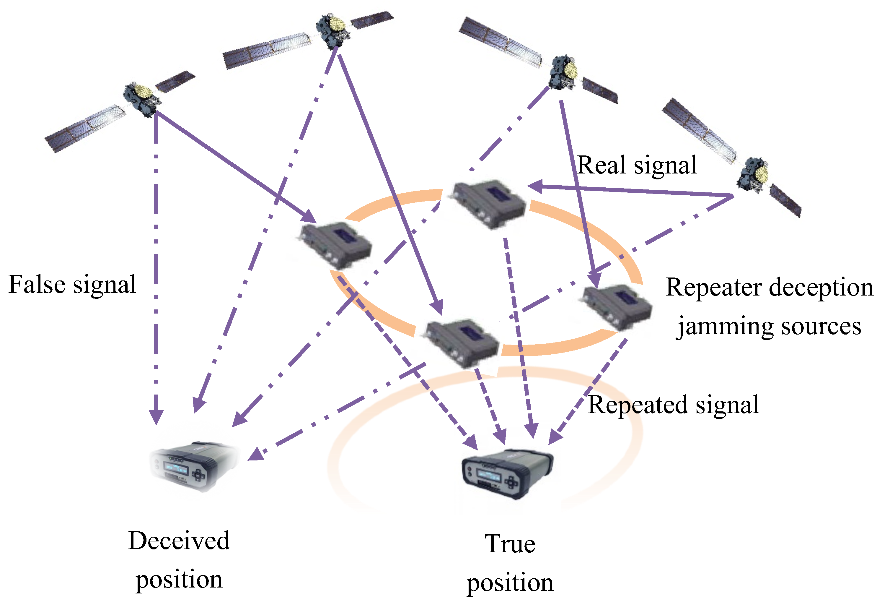
Zhang et al. [91] proved the advantages of multi-station repeater deception jamming and the necessity of optimizing the deployment of deception jamming sources. Compared with single-station forward deception jamming, multi-station repeater deception jamming can achieve area mapping and track mapping. Based on the principle of repeater jamming, four repeater jamming sources deployment is exemplified. The schematic diagram of four repeater jamming source deployments is shown in Figure 12.
The distance relationship of four repeater jamming sources deployment should be expressed as follows [91]:
S 1 D = S 1 R 1 + R 1 T + c t 1 S 2 D = S 2 R 2 + R 2 T + c t 2 S 3 D = S 3 R 3 + R 3 T + c t 3 S 4 D = S 4 R 4 + R 4 T + c t 4
wherein, S i is the i satellite in the positioning area, R i is the i repeater deception jamming source, t i is the signal delay of the i repeater deception jamming source, T is the true position of the receiver, D is the deceived position of the receiver, c is the speed of light, S i D is the distance from S i to D , S i R i is the distance from S i to R i , and R i T is distance from R i to T .
According to the principle of repeater deception jamming and the continuity of the mapping relationship, the area near the true position T is mapped to the area near the deceived position D . The mapping relationship can be expressed as follows [91]:
S 1 D + c t T = S 1 R 1 + R 1 T + c t 1 S 2 D + c t T = S 2 R 2 + R 2 T + c t 2 S 3 D + c t T = S 3 R 3 + R 3 T + c t 3 S 4 D + c t T = S 4 R 4 + R 4 T + c t 4
wherein, t T is the amount of change in receiver clock difference between T and T .
Using the Newton iterative method, the above formula is linearized as follows:
x D x S 1 S 1 D y D y S 1 S 1 D z D z S 1 S 1 D c x D x S 2 S 2 D y D y S 2 S 2 D z D z S 2 S 2 D c x D x S 3 S 3 D y D y S 1 S 3 D z D z S 1 S 3 D c x D x S 4 S 4 D y D y S 4 S 4 D z D z S 4 S 4 D c Δ x Δ y Δ z Δ t T = S 1 R 1 + R 1 T + c t 1 S 1 D S 2 R 2 + R 2 T + c t 2 S 2 D S 3 R 3 + R 3 T + c t 3 S 3 D S 4 R 4 + R 4 T + c t 4 S 4 D
wherein, x S i , y S i , z S i are three-dimensional coordinates of the i satellite, x D , y D , z D are three-dimensional coordinates of the deceived position, ( Δ x , Δ y , Δ z ) are iterative position variation of the deceived position, and Δ t T is iterative clock difference variation of t T .
In order to establish a good mapping relationship, according to [91], the position variation of the true position of the receiver and the position variation of the deceived position should be as similar as possible. The mapping relationship is expressed as follows:
x S 2 x S 1 S 1 D + S 2 D y S 2 y S 1 S 1 D + S 2 D z S 2 x S 1 S 1 D + S 2 D x S 3 x S 2 S 2 D + S 3 D y S 3 y S 2 S 2 D + S 3 D z S 3 x S 2 S 2 D + S 3 D x S 4 x S 3 S 3 D + S 4 D y S 4 y S 3 S 3 D + S 4 D z S 2 x S 1 S 3 D + S 4 D Δ x T Δ y T Δ z T = x R 2 x R 1 R 1 T + R 2 T y R 2 y R 1 R 1 T + R 2 T z R 2 x R 1 R 1 T + R 2 T x R 3 x R 2 R 2 T + R 3 T y R 3 y R 2 R 2 T + R 3 T z R 3 x R 2 R 2 T + R 3 T x R 4 x R 3 R 3 T + R 4 T y R 4 y R 3 R 3 T + R 4 T z R 2 x R 1 R 3 T + R 4 T Δ x D Δ y D Δ z D
wherein, x R i , y R i , z R i are three-dimensional coordinates of the i repeater deception jamming source, and ( Δ x T , Δ y T , Δ z T ) and ( Δ x D , Δ y D , Δ z D ) are iterative position variations of the true and deceived position.
To ensure that the area near the true position can be proportionally mapped to the area near the deceived position, the following equations should be guaranteed to hold:
Δ x T Δ y T Δ z T = Δ x D Δ y D Δ z D
x S 2 x S 1 S 1 D + S 2 D y S 2 y S 1 S 1 D + S 2 D z S 2 x S 1 S 1 D + S 2 D x S 3 x S 2 S 2 D + S 3 D y S 3 y S 2 S 2 D + S 3 D z S 3 x S 2 S 2 D + S 3 D x S 4 x S 3 S 3 D + S 4 D y S 4 y S 3 S 3 D + S 4 D z S 2 x S 1 S 3 D + S 4 D = x R 2 x R 1 R 1 T + R 2 T y R 2 y R 1 R 1 T + R 2 T z R 2 x R 1 R 1 T + R 2 T x R 3 x R 2 R 2 T + R 3 T y R 3 y R 2 R 2 T + R 3 T z R 3 x R 2 R 2 T + R 3 T x R 4 x R 3 R 3 T + R 4 T y R 4 y R 3 R 3 T + R 4 T z R 2 x R 1 R 3 T + R 4 T
Solving the above equation will obtain the deployment of repeater deception jamming sources. It can be seen that the deployment is closely related to the three-dimensional coordinates of the satellite and the true position of the receiver.
Wan et al. [92] proposed a method of multi-station repeater deception jamming source layout based on delay control, which can achieve accurate control of the forwarding delay by reasonably deploying the parameter information such as jamming source location and the forwarding height angle. Taking the four-station and single-station repeater jamming model as an example, from the perspective of the mapping of the real point neighborhood and the change of the clock difference of the receiver in neighborhood conditions, Yan et al. [61] obtained an easy-to-implement deception jamming source deployment method. It is also pointed out that in the four-station repeater deception jamming model, the deployment of deception jamming sources will affect the mapping relationship of the real point domain. When the deception jamming source is deployed on the link between the real point and the satellite and the corresponding line segment meets a certain proportion, the deception jamming source can better map the real point neighborhood to the virtual point neighborhood, thus achieving a better deception effect. However, this deployment method has a relative delay, and the receiver can realize deception detection through a detection algorithm.
In summary, the research on the deployment of deception jamming sources mainly focuses on repeater jamming sources. By controlling the location of repeater jamming sources, the signal delay and receiver clock difference are controlled, overcoming the shortcomings of repeater deception jamming, and thereby improving the effectiveness of deception jamming and expanding the effective range of jamming. While the research on the deployment of generation jamming sources is still at the stage of assumption and theoretical analysis, currently, anti-deception jamming techniques based on signal arrival direction or angle of arrival detection can already be used to detect deception jamming signals in a single direction. Implementing advanced distributed deception jamming by optimizing the deployment of multiple deception jamming sources to compensate for the shortcomings of a single generated deception jammer will be the focus of current deception jamming technology research.

4. Future Research Direction and Development Trend

To sum up, four future research directions of satellite navigation jamming technology are summarized.

4.1. Research on Evaluation System for Satellite Navigation Jamming

At present, there are few research results on the evaluation of suppression jamming and deception jamming effects, and the authority is insufficient. We still lack a reasonable and complete evaluation system of suppression jamming and deception jamming effects and evaluation methods that are consistent with the actual application scenarios. Most of the research only selects one or a few evaluation criteria for jamming methods or anti-jamming methods by which to analyze jamming or anti-jamming effects. The jamming efficiency evaluation system is not perfect. However, the navigation countermeasure scenario in the actual electromagnetic environment is relatively more complex. First of all, in the actual navigation countermeasure scenario, suppression jamming and deception jamming are usually combined to form composite jamming which acts on the target receiver. It is not realistic to only have suppression jamming or deception jamming. Secondly, the deployment strategy of composite jamming sources also affects the jamming effect to varying degrees. Therefore, the current evaluation method for the efficiency of suppression jamming and deception jamming is too simple and idealistic. Building an evaluation system for satellite navigation jamming based on the cooperative evaluation of suppression jamming and deception jamming is conducive to the optimization of navigation countermeasures-related technologies and equipment, as well as the evaluation of the cooperative deployment effect of composite jamming sources.

4.2. Research on Jamming Suppression Method for Antenna Array

Antenna array anti-jamming technology is the most effective anti-jamming method—at present—which can suppress multiple narrowband and broadband jamming. Therefore, the most important navigation equipment is equipped with the GNSS array receiver, and the jamming suppression effect is also weakened. It is necessary to study the suppression jamming for the antenna array.
From the angle of the jamming principle, the research of the suppression jamming method for antenna array can be considered from two perspectives: the number of suppression jamming sources and the type of suppression jamming.
First of all, according to the jamming principle, when the number of jamming sources exceeds the number of GNSS array receiver antennas—that is, the array degree-of-freedom—the anti-jamming performance of the receiver will decline sharply. At present, most anti-jamming algorithms only consider the anti-jamming performance when the number of jamming sources is less than or equal to the number of antenna elements. There are few research articles on the methods of suppressing jamming with super-degree-of-freedom, lacking theoretical derivation and analysis. From the perspective of suppression jamming source deployment, although the use of multiple jamming sources to implement jamming is considered, the current main focus is on achieving the coverage of jamming area through networked cooperative deployment, without considering the impact of antenna array super-degree-of-freedom jamming on the GNSS array receiver.
Secondly, the current suppression jamming technology mainly focuses on how to evaluate the jamming effect of a single jamming style. In fact, GNSS faces a very complex navigation countermeasure environment, and a single suppression jamming scenario only exists in the simulation analysis. New jamming styles such as super-degree-of-freedom composite jamming and non-stationary non-continuous jamming will be the mainstream of antenna array jamming research in the future.

4.3. Research on Deception Jamming Method for Integrated Navigation

At present, modern navigation countermeasures equipment such as unmanned aerial vehicles and unmanned ships are not only equipped with satellite navigation receivers but also loaded with other navigation systems. However, at present, the research on deception jamming still mainly focuses on satellite navigation, while the research on deception jamming methods under the integrated navigation mode combining GNSS and other systems is relatively small. If the navigation countermeasure equipment is equipped with integrated navigation, blind deception jamming without considering the actual operation track of the equipment will usually lead to deception failure. However, there is less research on track deception, and there is little research on controlling the target to move according to the predetermined position and achieving precise position deception. In addition, the existence of deception jamming detection algorithms on modern navigation countermeasure equipment makes it more difficult to implement covert deception jamming for integrated navigation compared with target equipment only equipped with GNSS. In addition, the control system and integrated navigation means used by different types of navigation countermeasure equipment are different, and the effect of the same deception jamming strategy is not consistent. Therefore, it is necessary to continuously optimize the deception jamming methods and strategies for integrated navigation through multiple deception jamming tests, and indirectly to improve the anti-deception performance of the equipment while improving the deception performance of deception-integrated navigation.

4.4. Research on Deception Jamming Method for Military Signals

Compared with generated deception jamming, the most obvious advantage of repeater deception jamming is that it can be used to deceive military signals. However, the current research on repeater deception jamming involves less experimental analysis of military signal deception. In addition, although there have been reports of successful deception of military equipment, the specific technical details of each event have not been explained and analyzed in detail. The effect of repeater deception on military signals is still in the exploration stage, and the research on other deception jamming methods for military signals is also in a blank state.

5. Conclusions

As an important branch of navigation countermeasure technology, satellite navigation jamming technology has attracted extensive attention. This paper introduces suppression jamming and deception jamming from three perspectives: jamming classification, jamming efficiency evaluation, and jamming source deployment. However, due to the signal system, the current development of satellite navigation anti-jamming technology is more rapid. Therefore, this paper points out the technical defects and the development direction of satellite navigation jamming technology. Our findings are as follows: first, we currently lack of a complete jamming evaluation system by which to evaluate the effectiveness of suppression jamming and deception jamming; second, for antenna array anti-jamming technology, super freedom jamming, and non-stationary jamming will become mainstream; and finally, there is limited research on deception jamming techniques for integrated navigation and military codes, which will become a hot research topic in the future.

Author Contributions

Conceptualization, X.L., L.C. and Z.L.; resources, W.L. and W.X.; writing—original draft preparation, X.L.; writing—review and editing, L.C. and Z.L.; project administration, F.W. and P.L. These authors contributed equally: X.L. and L.C. All authors have read and agreed to the published version of the manuscript.

Funding

This research was funded by the National Natural Science Foundation of China (62003354).

Data Availability Statement

Not applicable.

Acknowledgments

The research in this article is supported by the College of Electronic Sciences.

Conflicts of Interest

The authors declare no conflict of interest.

References

  1. Lu, J.; Guo, X.; Su, C. Global capabilities of BeiDou navigation satellite system. Satell. Navig. 2020, 1, 27. [Google Scholar] [CrossRef]
  2. Ma, C.; Yang, J.; Chen, J.; Qu, Z.; Zhou, C. Effects of a Navigation Spoofing Signal on a Receiver Loop and a UAV Spoofing Approach. GPS Solut. 2020, 24, 16. [Google Scholar]
  3. Psiaki, M.L.; Humphreys, T.E. GNSS Spoofing and Detection. Proc. IEEE 2016, 104, 1258–1270. [Google Scholar] [CrossRef]
  4. Lorraine, K.; Ramarakula, M.A. Comprehensive Survey on GNSS Interferences and the Application of Neural Networks for Anti-jamming. IETE J. Res. 2021, 0, 1–20. [Google Scholar] [CrossRef]
  5. Wang, Y.; Wang, Y.; Sun, X. Study on Index System of Satellite Navigation Jamming Effect Evaluation. Commun. Countermeas. 2013, 32, 33–37. [Google Scholar]
  6. Wang, Y.; Hao, J.; Liu, W. Evaluation Method for Effectiveness of GNSS Spoofer. Acta Armamentarii 2020, 41, 108–117. [Google Scholar]
  7. Zhang, X. GPSIII Satellite Navigation Interference Scheme and Interference Source Optimization Deployment Method Design; Research Institute of Electronic Science and Technology: Chengdu, China, 2017; pp. 5–76. [Google Scholar]
  8. Oshman, Y.; Koifman, M. Robust GPS navigation in the presence of jamming and spoofing. In Proceedings of the AIAA Guidance Navigation and Control Conference and Exhibit, Austin, TX, USA, 11–14 August 2003; pp. 1–11. [Google Scholar]
  9. Hu, H.; Wei, N. A study of GPS jamming and anti-jamming. In Proceedings of the 2nd International Conference on Power Electronics and Intelligent Transportation System, Shenzhen, China, 19–20 December 2009; pp. 388–391. [Google Scholar]
  10. Wang, H.; Chang, Q.; Xu, Y. An Integrated Beam Anti-Jamming Algorithm for Low-Orbit Navigation Augmentation. IEEE Commun. Lett. 2022, 26, 877–881. [Google Scholar] [CrossRef]
  11. Sun, Y.; Chen, F.; Lu, Z.; Wang, F. Anti-Jamming Method and Implementation for GNSS Receiver Based on Array Antenna Rotation. Remote Sens. 2022, 14, 4774. [Google Scholar] [CrossRef]
  12. Islam, S.; Bhuiyan, M.; Thombre, S.; Kaasalainen, S. Combating Single-Frequency Jamming through a Multi-Frequency Multi-Constellation Software Receiver A Case Study for Maritime Navigation in the Gulf of Finland. Sensors 2022, 22, 2294. [Google Scholar] [CrossRef]
  13. Karsi, M.; Lindsey, W. Effects of CW interference on phase-locked loop performance. Commun. IEEE Trans. 2000, 48, 886–896. [Google Scholar] [CrossRef]
  14. Mao, H.; Wu, D.; Lu, H.; Yan, Z. Analysis of a New Wideband Blanket Jamming Type to GPS Receiver. J. Electron. Inf. Technol. 2014, 36, 2930–2933. [Google Scholar]
  15. Qin, W.; Dovis, F. Situational Awareness of Chirp Jamming Threats to GNSS Based on Supervised Machine Learning. IEEE Trans. Aerosp. Electron. Syst. 2022, 58, 1707–1720. [Google Scholar] [CrossRef]
  16. Li, B.; Qiao, J.; Lu, Z.; Yu, X.; Song, J.; Lin, B.; Li, X. Influence of sweep jamming on satellite navigation time-domain anti-jamming. Front. Phys. 2023, 10, 1063474. [Google Scholar] [CrossRef]
  17. Mitch, R.H.; Dougherty, R.C.; Psiaki, M.L.; Powell, S.P.; O’Hanlon, B.W.; Bhatti, J.A.; Humphreys, T.E. Signal Characteristics of Civil GPS Jammers. In Proceedings of the International Technical Meeting of Satellite Division of the Institute of Navigation, Portland, OR, USA, 20–23 September 2011; pp. 364–371. [Google Scholar]
  18. Zhao, X.; Huang, X.; Tang, X.; Feng, X.; Sun, G. Chirp pseudo-noise signal and its receiving scheme for LEO enhanced GNSS. IET Radar Sonar Navig. 2022, 16, 1751–1758. [Google Scholar] [CrossRef]
  19. Baek, J.; Seungsoo, Y.; Sun, Y. Jamming Effect Analysis of Two Chinese GNSS BeiDou-II Civil Signals. Int. J. Electr. Comput. Eng. 2012, 2, 840–845. [Google Scholar] [CrossRef]
  20. Wang, J.; Sun, Z.; Zhang, Y. Study on Optimal Jamming Signal of GPS System. Comput. Meas. Control 2016, 24, 257–260. [Google Scholar]
  21. Konovaltsev, A.; Lorenzo, D.; Hornbostel, A.; Enge, P. Mitigation of continuous and pulsed radio jamming with GNSS antenna arrays. In Proceedings of the 21st International Technical Meeting of the Satellite Division of the Institute of Navigation (ION GNSS 2008), Savannah, GA, USA, 16–19 September 2008; pp. 2786–2795. [Google Scholar]
  22. Olivier, B. Analysis of the SNR Loss Distribution With Covariance Mismatched Training Samples. IEEE Trans. Signal Process. 2020, 68, 5759–5768. [Google Scholar]
  23. Wang, J.; Liu, W.; Ou, G.; Xiao, W.; Wang, H.; Dong, T. Channel scintillations of array global navigation satellite system receiver under distributed intermittent jammings. IET Radar Sonar Navig. 2022, 17, 227–235. [Google Scholar] [CrossRef]
  24. Li, Y. Research on Jamming and Anti-Jamming about Satellite Navigation Receiver with Array Antenna; Xidian University: Xi’an, China, 2017; pp. 19–27. [Google Scholar]
  25. Huang, L.; Lu, Z.; Ren, C.; Liu, Z.; Xiao, Z.; Song, J.; Li, B. Research on Detection Technology of Spoofing under the Mixed Narrowband and Spoofing Interference. Remote Sens. 2022, 14, 2506. [Google Scholar] [CrossRef]
  26. Moussa, M.; Osman, A.; Tamazin, M.; Korenberg, M.; Noureldin, A. Enhanced GPS narrowband jamming detection using high-resolution spectral estimation. GPS Solut. 2017, 21, 475–485. [Google Scholar] [CrossRef]
  27. Gong, Y.; Wang, L.; Yao, R.; Zhang, Z. A Robust Method to Suppress Jamming for GNSS Array Antenna Based on Reconstruction of Sample Covariance Matrix. Int. J. Antennas Propag. 2017, 2017, 9764283. [Google Scholar] [CrossRef] [Green Version]
  28. Wu, R.; Dong, J.; Wang, M. Wearable Polarization Conversion Metasurface MIMO Antenna for Biomedical Applications in 5 GHz WBAN. Biosensors 2023, 13, 73. [Google Scholar] [CrossRef] [PubMed]
  29. Fan, G.; Tang, X.; Nie, J.; Huang, Y.; Sun, G. A Zero Bias Frequency-Domain Jamming Suppressor for GNSS Receivers. IEICE Trans. Commun. 2016, 99, 2081–2086. [Google Scholar] [CrossRef]
  30. Pan, Y.; Dong, J. Design and optimization of an ultrathin and broadband polarization-insensitive fractal FSS using the improved bacteria foraging optimization algorithm and curve fitting. Nanomaterials 2023, 13, 191. [Google Scholar] [CrossRef]
  31. Huo, S.; Nie, J.; Tang, X.; Wang, F. Minimum Energy Block Technique Against Pulsed and Narrowband Mixed Interferers for Single Antenna GNSS Receivers. IEEE Commun. Lett. 2015, 19, 1933–1936. [Google Scholar] [CrossRef]
  32. Betz, J.W.; Kolodziejski, K.R. Generalized Theory of Code Tracking with an Early-late Discriminator Part 1 Lower Bound and Coherent Processing. IEEE Trans. Aerosp. Electron. Syst. 2009, 45, 1538–1550. [Google Scholar] [CrossRef]
  33. Betz, J.W.; Kolodziejski, K.R. Generalized Theory of Code Tracking with an Early-late Discriminator Part 2 Noncoherent Processing and Numerical Results. IEEE Trans. Aerosp. Electron. Syst. 2009, 45, 1551–1564. [Google Scholar] [CrossRef]
  34. Bek, M.K.; Shaheen, E.M.; Elgamel, S.A. Classification and Mathematical Expression of Different Jamming Signals on a GPS Receiver. Navigation 2015, 62, 23–37. [Google Scholar] [CrossRef]
  35. Balaei, A.T.; Dempster, A.G.; Presti, L.L. Characterization of the Effects of CW and Pulse CW Jamming on the GPS Signal Quality. IEEE Trans. Aerosp. Electron. Syst. 2009, 45, 1418–1431. [Google Scholar] [CrossRef]
  36. Jaegyu, J.; Matteo, P.; Bernd, E. CW Jamming Effects on Tracking Performance of GNSS Receivers. IEEE Trans. Aerosp. Electron. Syst. 2012, 48, 243–258. [Google Scholar] [CrossRef]
  37. Bek, M.K.; Shaheen, E.M.; Elgamel, S.A. Mathematical analyses of pulse jamming signal on post-correlation carrier-to-noise ratio for the global positioning system receivers. IET Radar Sonar Navig. 2015, 9, 266–275. [Google Scholar] [CrossRef]
  38. Hu, X.; Liu, Y.; Ran, Y.; Ke, T. Tracking performance evaluation of GNSS signals in CW jamming. J. Huazhong Univ. Sci. Technol. 2010, 38, 5–8. [Google Scholar]
  39. Zhang, J.; Lohan, E.S. Effect of Narrowband Jamming on Galileo E1 Signal Receiver Performance. Int. J. Navig. Obs. 2011, 2011, 959871. [Google Scholar] [CrossRef] [Green Version]
  40. Zhang, K.; Zeng, F.; Ou, X.; Zhao, Y. Analysis of GPS Blanket Jamming Effects. Commun. Technol. 2018, 51, 2544–2548. [Google Scholar]
  41. Mojtaba, H.; Hamid, R.; Mahmood, S. Robust adaptive beamforming in impulsive noise environments. IET Radar Sonar Navig. 2019, 13, 2145–2150. [Google Scholar]
  42. Cheng, L.; Zhang, S.; Zeng, F. A Study on Optimized Deployment of Satellite Navigation Jammers. Fire Control Command Control 2015, 40, 43–46. [Google Scholar]
  43. Huang, Y.; Huang, L. Design and Simulation of the Algorithm on the Distribution and Coverage of GPS Jamming Shells. In Proceedings of the International Conference on Intelligent Networks & Intelligent Systems, Shenyang, China, 1–3 November 2010; pp. 634–637. [Google Scholar]
  44. Yang, E.; Erdogan, A.; Arslan, T.; Barton, N. Multi-objective evolutionary optimizations of a space-based reconfigurable sensor network under hard constraints. Soft Comput. A Fusion Found. Methodol. Appl. 2011, 15, 25–36. [Google Scholar] [CrossRef]
  45. Quintao, F.; Nakamura, F.; Mateus, G. Evolutionary algorithm for the dynamic coverage problem applied to wireless sensor networks design. In Proceedings of the 2005 IEEE Congress on Evolutionary Computation, Edinburgh, UK, 2–5 September 2005; pp. 21–25. [Google Scholar]
  46. Yan, Z.; Wu, D.; Jiang, W.; Liu, H.; Mao, H. Deployment of Aerial Jammers in Network-Type GPS Jamming System. Electron. Opt. Control 2013, 20, 37–39. [Google Scholar]
  47. Fu, Y.; Zhu, K.; Han, Q.; Xu, Y. A deployment method of navigation signal jammers. J. Navig. Position. 2020, 8, 110–114. [Google Scholar]
  48. Ni, S.; Cui, J.; Cheng, N.; Liao, Y. Detection and elimination method for deception jamming based on an antenna array. Int. J. Distrib. Sens. Netw. 2018, 14, 1550147718774466. [Google Scholar] [CrossRef]
  49. Todd, E.; Brent, M.; Mark, L.; Brady, W.; Paul, M. Assessing the Spoofing Threat Development of a Portable GPS Civilian Spoofer. In Proceedings of the 21st International Technical Meeting of the Satellite Division of the Institute of Navigation (ION GNSS 2008), Savannah, GA, USA, 16–19 September 2008; pp. 1–6. [Google Scholar]
  50. Todd, H.; Jahshan, B.; Daniel, S.; Kyle, W. The Texas Spoofing Test Battery Toward a Standard for Evaluating GPS Signal Authentication Techniques. In Proceedings of the International Technical Meeting of Satellite Division of the Institute of Navigation, Nashville, TN, USA, 17–21 September 2012; pp. 1–7. [Google Scholar]
  51. Hanlon, B.; Psiaki, M.; Humphreys, T.; Bahatti, J.A. Real-Time Spoofing Detection Using Correlation Between Two Civil GPS Receivers. In Proceedings of the International Technical Meeting of Satellite Division of the Institute of Navigation, Nashville, TN, USA, 17–21 September 2012; pp. 2–4. [Google Scholar]
  52. He, L.; Li, W.; Guo, G. Study on GPS generated spoofing attacks. Appl. Res. Comput. 2016, 33, 2405–2408. [Google Scholar]
  53. Sheng, Y.; Li, H.; Zhou, S.; Zhang, B. Research of GPS Generated Spoofing Method. Foreign Electron. Meas. Technol. 2018, 37, 39–43. [Google Scholar]
  54. He, X.; Liao, K.; Peng, S.; Tian, Z.; Huang, J. Interrupted-Sampling Repeater Jamming-Suppression Method Based on a Multi-Stages Multi-Domains Joint Anti-Jamming Depth Network. Remote Sens. 2022, 14, 3445. [Google Scholar] [CrossRef]
  55. Wang, H.; Yao, Z.; Fan, Z.; Zheng, T. A Negative Time-delay Correction Method for Repeater Deception Jamming Signal. Telecommun. Eng. 2015, 55, 1255–1259. [Google Scholar]
  56. Guo, Y.; Wu, M.; Tang, K.; Tie, J.; Li, X. Covert Spoofing Algorithm of UAV Based on GPS/INS-Integrated Navigation. IEEE Trans. Veh. Technol. 2019, 68, 6557–6564. [Google Scholar] [CrossRef]
  57. Zhen, C.; Wang, Q.; Jiang, Y.; Wang, X. Time Delay Control Method for GNSS Repeater Deception Jamming. Mod. Navig. 2022, 13, 79–84. [Google Scholar]
  58. Daniel, P.S.; Jahshan, A.B.; Todd, E.H.; Aaron, A.F. Evaluation of smart grid and civilian UAV vulnerability to GPS spoofing attacks. In Proceedings of the International Technical Meeting of Satellite Division of the Institute of Navigation, Nashville, TN, USA, 17–21 September 2012; pp. 1–15. [Google Scholar]
  59. Costa, F.; Glauberto, L.; Silveira, L.F.; Valderrama, C.; Xavier-de-Souza, S. Variance-Triggered Two-Step GPS Acquisition. Sensors 2019, 19, 3177. [Google Scholar] [CrossRef] [Green Version]
  60. Kim, T.; Sin, C.S.; Lee, S. Analysis of Effect of Spoofing Signal in GPS Receiver. In Proceedings of the 12th International Conference on Control Automation and Systems, Jeju, Republic of Korea, 17–21 October 2012; pp. 2083–2087. [Google Scholar]
  61. Yan, Z.; Wu, D.; He, J.; Liu, H.; Mao, H. Deployment Method of Jammer in GPS Repeater Deception Jamming. Mod. Radar 2015, 37, 375–379. [Google Scholar]
  62. Ali, J.J.; Ali, B.; John, N.; Gérard, L. GPS Spoofer Countermeasure Effectiveness Based on Signal Strength Noise Power and C/N0 Measurements. Int. J. Satell. Commun. Netw. 2012, 30, 181–191. [Google Scholar]
  63. Pang, J.; Nie, S.; Nie, J.; Ou, G. An Overview to GNSS Spoofing Technologies. Fire Control Command Control 2016, 41, 1–4. [Google Scholar]
  64. Wang, H.; Yao, Z.; Fan, Z.; Zhen, T. Experiment Study of Spoofing Jamming on GPS Receiver. Fire Control Command Control 2016, 41, 184–187. [Google Scholar]
  65. Liu, Y.; Sun, W.; Yan, S. Efficiency Analysis of Repeater Deception Jamming GPS Repeater. J. Air Force Radar Acad. 2004, 4, 44–46. [Google Scholar]
  66. Tippenhauer, N.O.; Pöpper, C.; Rasmussen, K.B.; Čapkun, S. On the Requirements for Successful GPS Spoofing Attacks. In Proceedings of the 18th ACM Conference on Computer and Communications Security, Chicago, IL, USA, 17–21 October 2011; pp. 1–11. [Google Scholar]
  67. Ma, K.; Sun, X.; Nie, Y. Research on Key Technologies of GPS Generated Spoofing. Aerosp. Electron. Warf. 2014, 30, 624–626. [Google Scholar]
  68. Hu, Y.; Bian, S.; Cao, K.; Feng, G. Spoofing power control strategy for GNSS receiver. J. Chin. Inert. Technol. 2015, 23, 207–210. [Google Scholar]
  69. Humphreys, T.E.; Ledvina, B.M.; Psiaki, M.L.; O’Hanlon, B.W.; Kintner, J.P. Assessing the Spoofing Threat. GPS World 2009, 20, 28–38. [Google Scholar]
  70. Lv, H.; Zhai, J.; Wang, W. The Spoofing Threat and Anti-Spoofing Measurements Analysis for Satellite Navigation Receiver. In Proceedings of the Fourth China Satellite Navigation Academic Annual Conference, Wuhan, China, 15–17 May 2013; pp. 1–5. [Google Scholar]
  71. Kerns, A.; Shepard, D.; Bhatti, J.; Humphreys, T. Unmanned aircraft capture and control via GPS spoofing. J. Field Robot. 2014, 31, 617–636. [Google Scholar] [CrossRef]
  72. Ali, B.; Ali, J.; Vahid, D.; John, N.; Gerard, L. GNSS spoofing detection in handheld receivers based on signal spatial correlation. In Proceedings of the 2012 IEEE/ION Position, Myrtle Beach, SC, USA, 23–26 April 2012; pp. 1–4. [Google Scholar]
  73. Psiaki, M.; Hanlon, B.; Bhatti, J.; Shepard, D.; Humphreys, T. GPS Spoofing Detection via Dual-Receiver Correlation of Military Signals. IEEE Trans. Aerosp. Electron. Syst. 2013, 49, 2250–2267. [Google Scholar] [CrossRef] [Green Version]
  74. Humphreys, T. Detection Strategy for Cryptographic GNSS Anti-Spoofing. Aerosp. Electron. Syst. IEEE Trans. 2013, 49, 1073–1090. [Google Scholar] [CrossRef]
  75. Kyle, W.; Daniel, S.; Todd, H. Straight Talk on Anti-Spoofing Securing the Future of PNT. GPS World 2012, 23, 32–43. [Google Scholar]
  76. Todd, E.; Jahshan, A.; Brent, M. The GPS Assimilator a Method for Upgrading Existing GPS User Equipment to Improve Accuracy Robustness and Resistance to Spoofing. In Proceedings of the International Technical Meeting of Satellite Division of the Institute of Navigation, Portland, OR, USA, 21–24 September 2010; p. 13. [Google Scholar]
  77. Kyle, D.; Daniel, P.; Jahshan, A.; Todd, E. An Evaluation of the Vestigial Signal Defense for Civil GPS Anti-Spoofing. In Proceedings of the International Technical Meeting of Satellite Division of the Institute of Navigation, Portland, OR, USA, 20–23 September 2011; Volume 4, pp. 2–6. [Google Scholar]
  78. Gao, Y.; Li, H.; Lu, M.; Feng, Z. Intermediate Spoofing Strategies and Countermeasures. Tsinghua Sci. Technol. 2013, 18, 599–605. [Google Scholar]
  79. Huang, L.; Lv, Z.; Wang, F. Spoofing Pattern Research on GNSS Receivers. J. Astronaut. 2012, 33, 884–890. [Google Scholar]
  80. Li, B.; Zhu, Y.; Cao, K.; Li, S.; Li, J. Modeling and Test on Spoof Jamming for Beidou Navigation Signal. J. Nav. Univ. Eng. 2019, 31, 23–27. [Google Scholar]
  81. Zhang, L.; Zhang, C.; Gao, Y. GNSS Spoofing and Detection(I): Typical Events and Development of Spoofing Technology. J. Navig. Position. 2021, 9, 1–7. [Google Scholar]
  82. Liu, Q.; Cheng, Y.; Wang, G.; Ma, Y.; Chen, S. Discussion on Deception and Anti-deception Technology of Beidou Satellite Navigation. Navig. Control 2021, 20, 24–32. [Google Scholar]
  83. Zhang, S.; Cheng, L.; Wang, B. Efficiency Analysis of Jamming on Cruise Missile Guided by GPS. Fire Control Command Control 2015, 40, 66–69. [Google Scholar]
  84. Liu, Y. INS/GNSS Integrated Navigation System Spoofing Detection Techniques; Northwestern Polytechnical University: Xian, China, 2019; pp. 17–40. [Google Scholar]
  85. Zhen, Y. Research on Deceptive Jamming Strategy of Satellite Navigation Receiver and Its Performance Evaluation; Hebei University of Science & Technology: Shijiazhuang, China, 2019; pp. 53–57. [Google Scholar]
  86. Wang, Y.; Hao, J.; Liu, W.; Wang, X.; Gao, Y. Indicator Detection Method of Spoofing Effectiveness of GNSS. Geomat. Spat. Inf. Technol. 2019, 42, 51–56. [Google Scholar]
  87. Wang, Y. Evaluation Indexes and Evaluation Methods of GNSS Spoofing Efficacy; Information Engineering University: Zhengzhou, China, 2020; pp. 23–74. [Google Scholar]
  88. Yang, J.; Zeng, F.; Sheng, H.; Zhu, L. A Jamming System Through Section Mapping for GPS Navigation. Chin. J. Electron. 2005, 33, 1036–1038. [Google Scholar]
  89. Zhang, S.; Yang, J.; Pan, G.; Zeng, F. GPS Inducing Jamming System through a Single Transmitter. Mod. Radar 2010, 32, 19–22. [Google Scholar]
  90. Zhen, S.; Zhen, Z.; Cao, Y. Single-station Forwarding Spoofing Scheme Based on Time Delay. Mod. Radar 2010, 9, 963–968. [Google Scholar]
  91. Zhang, S.; Miao, M.; Hou, S.; Han, Z.; Peng, D. A Study on the Performance Between Multi-transmitters and Single Transmitter GPS Inducing System. Mod. Radar 2013, 35, 11–15. [Google Scholar]
  92. Wan, Y.; Ma, P.; Nie, J.; Sun, G. Study of Multi-Station Retransmission Spoofing Methods Based on Protection of Fixed Target. GNSS World China 2016, 41, 60–65. [Google Scholar]
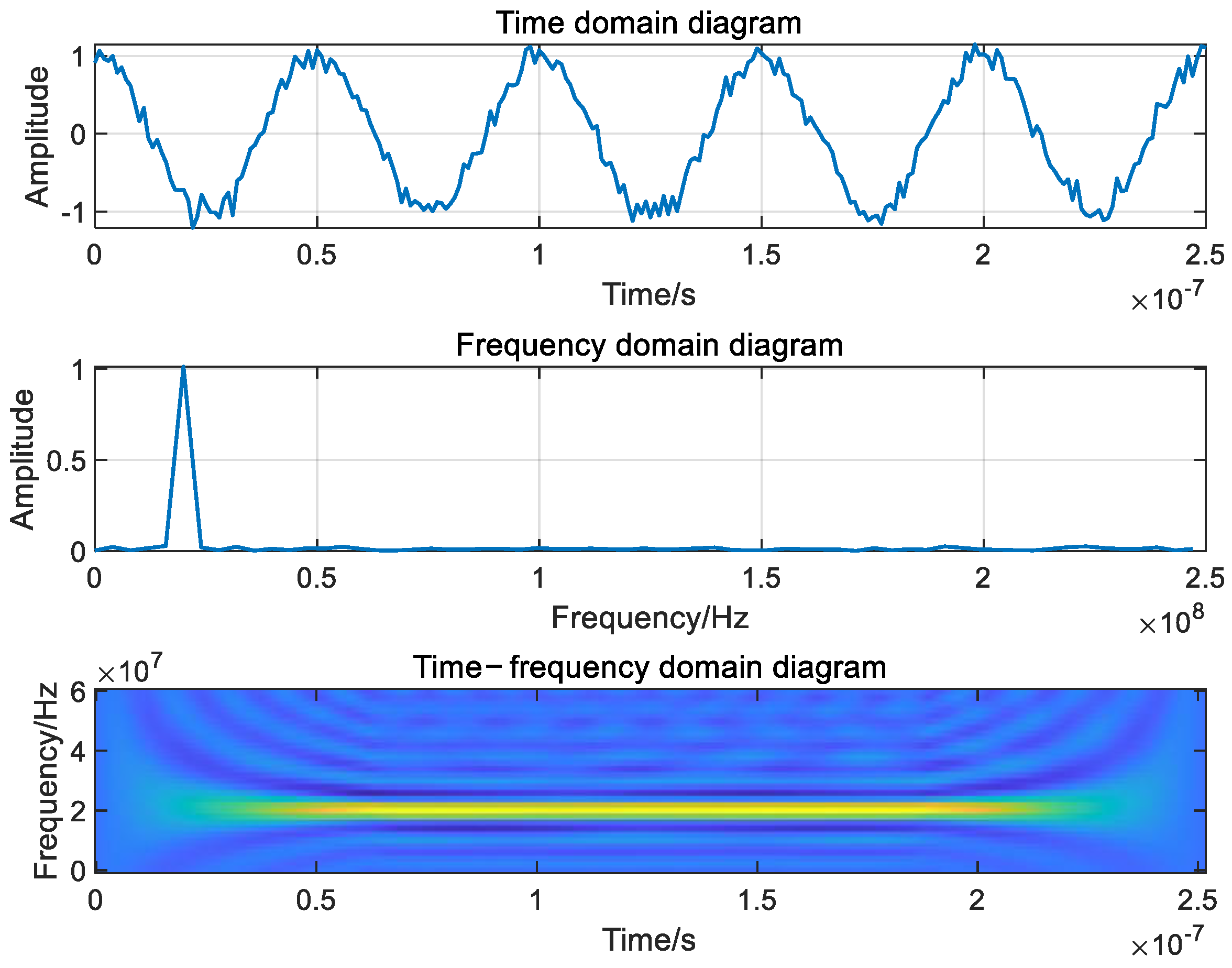
Figure 1. The signal characteristic diagram of Single-frequency jamming.
Machines 11 00768 g001
Figure 2. The signal characteristic diagram of pulse jamming.
Machines 11 00768 g002
Figure 3. The signal characteristic diagram of sweep jamming.
Machines 11 00768 g003
Figure 4. The signal characteristic diagram of BPSK modulated matched spectrum jamming.
Machines 11 00768 g004
Figure 5. The schematic diagram of suppression jamming deployment.
Machines 11 00768 g005
Figure 6. The flowchart of suppression jamming deployment.
Machines 11 00768 g006
Figure 7. The effect diagram of optimized deployment of suppression jamming.
Machines 11 00768 g007
Figure 8. The schematic diagram of traction jamming implementation process.
Machines 11 00768 g008
Figure 9. The schematic diagram of primary navigation deception jamming.
Machines 11 00768 g009
Figure 10. The schematic diagram of intermediate navigation deception jamming.
Machines 11 00768 g010
Figure 11. The schematic diagram of advanced navigation deception jamming.
Machines 11 00768 g011
Figure 12. The schematic diagram of four repeater jamming sources deployment.
Machines 11 00768 g012
Table 1. Navigation signal basic indicators.
Signal ProcessingBasic Indicator
Signal acquisitionSignal acquisition time
Signal acquisition sensitivity
Signal acquisition probability
Signal trackingNumber of channels
Pseudo-range precision
Tracking sensitivity
Signal demodulationError rate
Signal positioningPositioning accuracy
Table 2. Jamming efficiency evaluation indicators.
Influence FactorEfficiency Evaluation Index
Influence of jamming on signal acquisitionRelationship between jamming-to-signal ratio and acquisition probability
Relationship between jamming-to-signal ratio and the first acquisition time of the signal
Influence of jamming on signal trackingRelationship between jamming-to-signal ratio and pseudo-range accuracy
Influence of jamming on signal demodulationRelationship between jamming-to-signal ratio and error rate
Influence of jamming on signal positioningRelationship between jamming-to-signal ratio and positioning accuracy
Table 3. Comparison of deception methods with different signal generation modes.
Deception TypeAdvantageDisadvantageScope of Applications
Generated deception
Jamming [50,51,52,53]
High flexibility and controllable parametersUnable to deceive military code signalCivilian signal deception
Repeater deception
Jamming [56,57]
Can deceive military code signalsLow success rate of deceptionMilitary signal deception
Table 4. The comparison of deception methods with different implementation stages.
Implementation StageAdvantageDisadvantageResearch Focus
Signal acquisition stageImplementation is relatively simpleRelatively poor concealmentThe power control
[63,64,65,66,67]
The deception strategy
[53,63,68,69,70,71]
Signal tracking stageRelatively better concealmentImplementation is relatively difficultyThe traction deception technology [49,52,67,71,79]
Table 5. The comparison of deception methods with different implementation difficulty.
Implementation DifficultyDeceptive EffectDeception ScopeDeception Cost
Primary deceptionPoorWideHigh
Intermediate deceptionMediumNarrowHigher
Advanced deceptionHighNarrowerHighest
Disclaimer/Publisher’s Note: The statements, opinions and data contained in all publications are solely those of the individual author(s) and contributor(s) and not of MDPI and/or the editor(s). MDPI and/or the editor(s) disclaim responsibility for any injury to people or property resulting from any ideas, methods, instructions or products referred to in the content.