2. Description of Gas Cylinder Geometry and Composite String Winding Path
- A.
Definition of coordinate axes
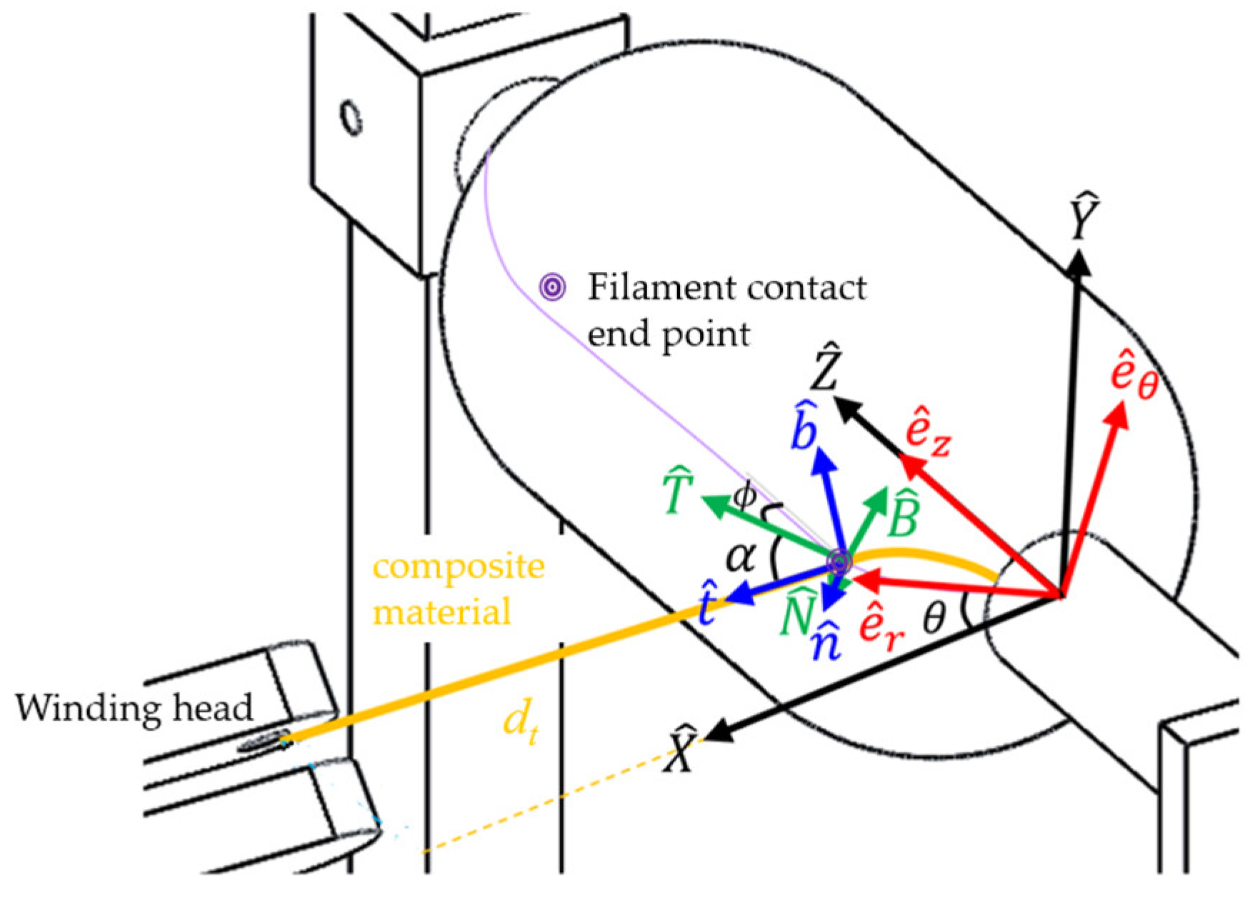
In this study, geodesics are used for the winding approach, which provides the shortest paths between two arbitrary points on a surface. Four coordinate systems are introduced as follows based on the longitude and latitude coordinates required by the geodesic system and the relationship between the standard local coordinate system.
- (a)
Standard local coordinate system.
The standard local coordinate system (
is fixed on the machine. In general, one vertex of the gas cylinder is selected as the coordinate origin. Then, the
-axis is defined as the axial direction of the gas cylinder directing toward the other vertex. The
-axis is kept perpendicular to the ground and pointing upward. Consequently, the
-axis is parallel to the ground, and the direction is toward the side where the filament winding head is located, as shown in
Figure 1.
- (b)
Cylindrical coordinate system.
The origin of the cylindrical coordinate system
moves according to the
coordinate value of the instantaneous contact point of the winding filament on the cylinder. The
-axis and the
-axis are in the same direction, and the
-axis is perpendicular to the
-axis and faces toward the instantaneous contact point. The
-axis is the cross product of the
-axis and the
-axis, and the angle between the
-axis and the
-axis is θ. The corresponding coordinate value in the cylindrical coordinate system of a point P at the standard local system can be obtained by:
- (c)
Latitude and longitude coordinate system.
The origin of the latitude–longitude coordinate system moves with the instantaneous contact point of the filament on the cylinder. The -axis is the normal vector of the cylinder surface, which directs outward the cylinder. The -axis is tangent to the meridian direction of the cylinder, and its component along the -axis is the same as the direction of movement of the winding head. The angle is the angle between the -axis and the direction of movement of the winding head, and its sign is the same as the -axis component in the -axis direction. The -axis is the cross-product of the -axis and the -axis.
For the winding head moving along with the positive and the negative
-axis direction, the relationship between the cylindrical coordinate system and the latitude-longitude coordinate system are shown in Equations (2) and (3), respectively.
- (d)
Winding coordinate system.
The winding coordinate system
and the latitude–longitude coordinate system
share the same origin, as shown in
Figure 1. The direction of the
-axis and the
-axis are the same, and the
-axis is tangent to the winding path. The
-axis is the direction of the cross product of the
-axis and the
-axis, where
is the angle between the
-axis and the
-axis, and its sign is the same as the
-axis component in the
-axis direction. For a point P
in the longitude-latitude coordinate system, the corresponding coordinate value
in the winding coordinate system can be obtained by:
Based on the definition of coordinates, the winding coordinate and the standard local coordinate of the forward and return winding paths can be obtained by Equations (5) and (6), respectively.
where
C and
S represent cosine and sine functions, respectively.
- B.
Winding path design
The winding mode mainly determines the complete path of the filament on the gas cylinder. However, the path is determined by winding process parameters and the composite material’s parameters, including the geometric shape of the gas cylinder, the winding filament properties, and the winding angle, etc. The winding angle is defined as the intersection angle between the winding filament’s primary axis and the cylinder’s meridian.
- (1)
Geometry of cylinder end.
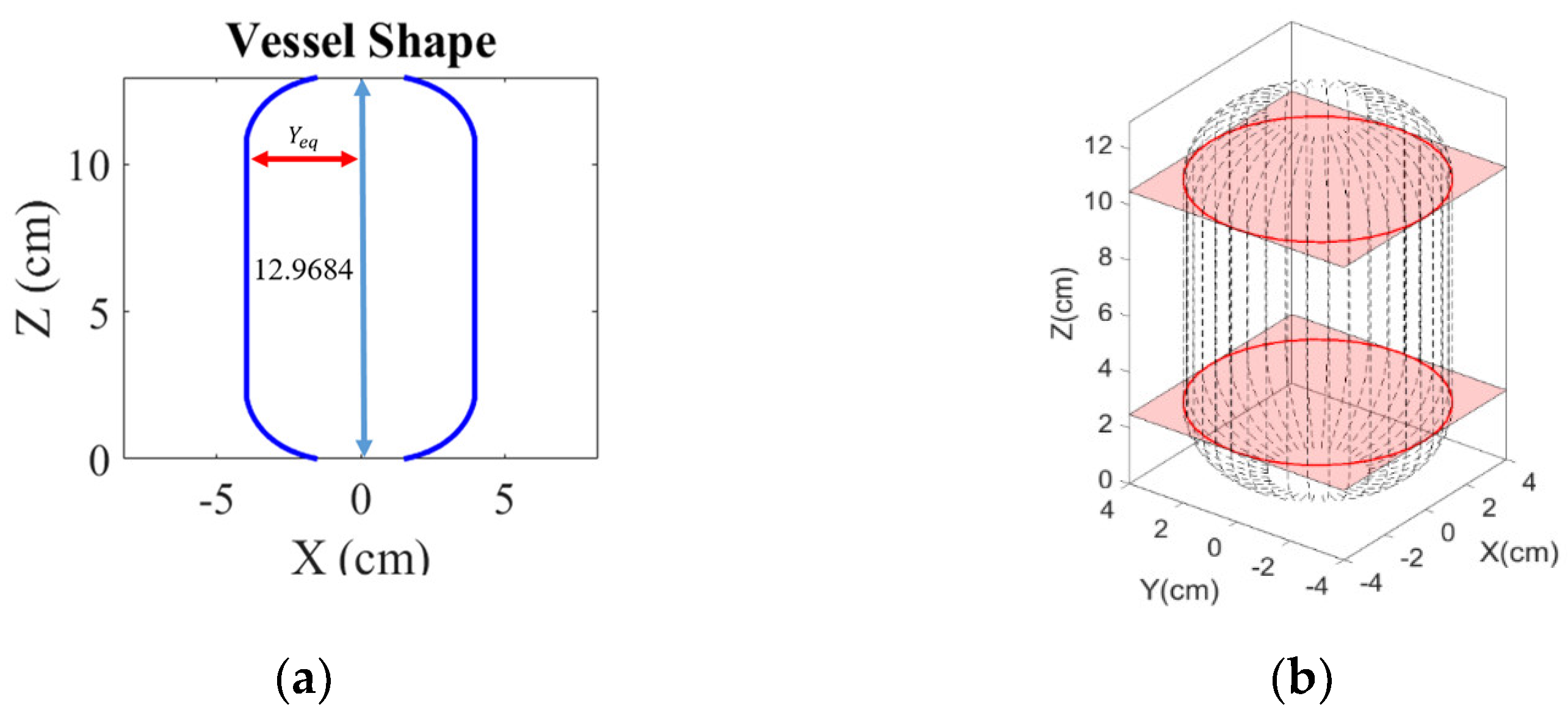
The key feature of the gas cylinder geometry is the shape of the end cap surface, in which the radius of the cylinder body is the radius of the joint ends of the end cap, also known as the equatorial radius (
). Based on the static equilibrium and the material properties of the winding strings, an optimal geometry [
18] of the gas cylinder end surface can be described by:
where
r is the ratio of the total external force on the end cap to the combined force of the storage pressure exerted on the end cap,
Yeq is the equatorial radius,
Y and
Z are the coordinate value of the end face on the
-axis and the
-axis, respectively. The fiber matrix combination ke is defined as follows.
where
and
are Young’s modulus, and
and
are the shear modulus of the composite. The composite material coefficients of carbon fiber strings T700/3234 (carbon fiber/epoxy resin) are referred to [
19], where
= 132 GPa,
= 10.3 GPa, and
= 0.25, it results
= 0.07803. In order to facilitate follow-up practical research, a small gas cylinder is used, where the minimum radius of the end surface is
, the equatorial radius is Yeq = R = 4 cm and the length of the cylinder is L = 8 cm, According to (7), the gas cylinder geometry is shown in
Figure 2.
- (2)
Winding path analysis.
Since the winding angle (
) of the gas cylinder side−surface is equal to the winding angle at the equatorial radius, determining the cylinder winding angle also determines the winding pattern of the end surface and the cylinder body. However, the friction between the filament and the cylinder must be considered in the end surface winding process to avoid slippage. Therefore, the winding angle (
) and the process parameters, such as the cylinder speed (
), the instantaneous contact point speed (
), are both closely related to the velocity (
vz) on the
-axis. Based on the no-slip consideration for the winding process, the angular velocity ratio can express the static friction coefficient required for the winding process without slippage [
20]. For a given static friction coefficient, the following is the no-slip constraint represented by the winding angle and the rotating speed of the gas cylinder.
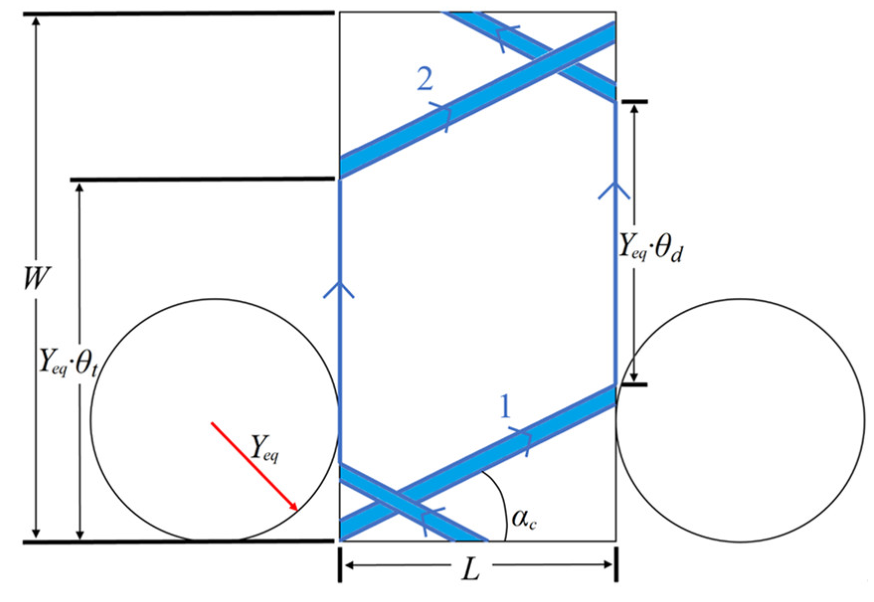
In
Figure 3, the velocity
at the instantaneous winding point is divided into two directions
and
, as presented in Equation (10) and its differentiation can be obtained by Equation (11).
For constant winding rate along the
direction, the following conditions are applied.
By Equations (10)–(13), the dynamics of the instantaneous winding point can be described by the nonlinear ordinary differential equation as follows.
Based on the winding boundary conditions
vz(0) = 0,
Y(0) =
Y0 at
Z = 0, and the initial angular velocity
of the cylinder, the integration of Equation (14) with respect to
Z gives.
Subsequently, the rotating speed
of the gas cylinder can be represented as:
Since
. keeps zero during the winding process, angle
between the winding filament and the latitude and longitude coordinate system can be obtained by converting
to the standard local coordinate system and substituted in Equation (15), where
is the component the winding speed
on the
-axis direction.
According to the friction and wear properties of composite [
21] and the tribological of carbon fiber composite materials [
22], the maximum static friction coefficient between the steel cylinder and the carbon fiber composite is about 0.3. Therefore, the constraint that no winding slippage occurs is rewritten as Equation (18).
Since
and
are real numbers and both Equations (16) and (17) are functions of
, the upper limit of the reasonable value of
can be obtained with a prescribed geometry of the gas cylinder. For winding motion ppurposes
can be described as a function of Z, which meets the limit constraints.
Figure 4 shows the limit and candidate functions for
, where
is described by the proposed function
with
Z0 = 0. For
= 0.9 and the initial value of the processing
Z is considered to be 0, then
Z can be a quadratic function of time, as shown in Equation (19), for
Z = [0, 2.4842], which covers the path located at the cylinder end cap.
Consequently, the dynamic response of
can be expressed as (20). In this way,
= 0 for
Z = 0.
Based on Equation (18) and the geometry of the gas cylinder in
Figure 4, the upper limit of the winding angle
at each time instant can be determined. For a smooth winding path from the cylinder end to the cylindrical surface, it is reasonable to set the upper limit of the winding angle for both ends the same as the cylindrical winding angle
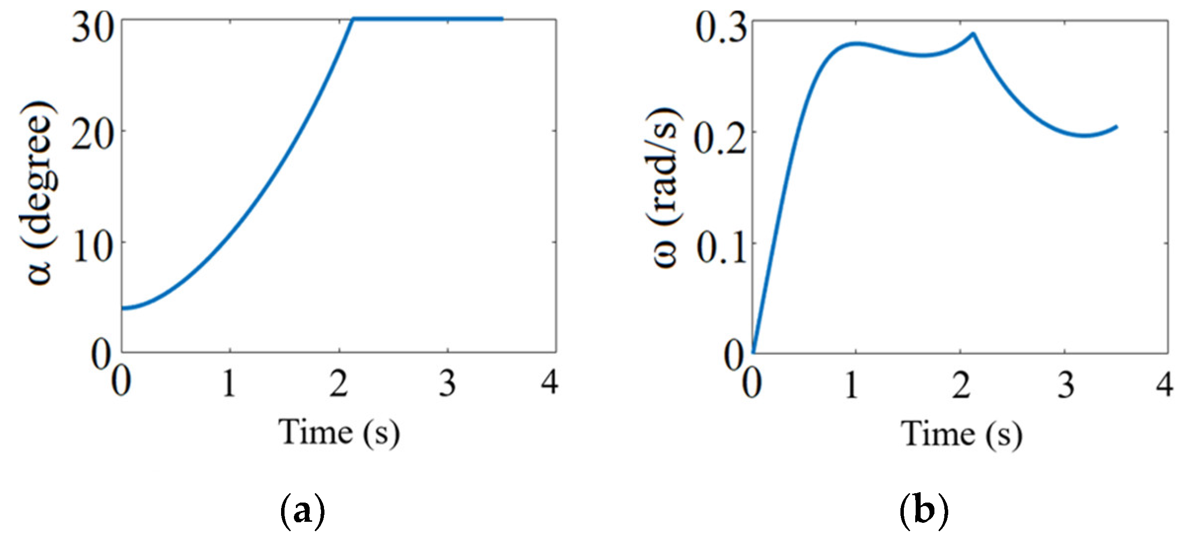
. Assuming that the tape width of the composite filament is 0.5 cm and
, the time response of the winding angle
and the cylinder rotating speed
on the one cylinder end are shown in
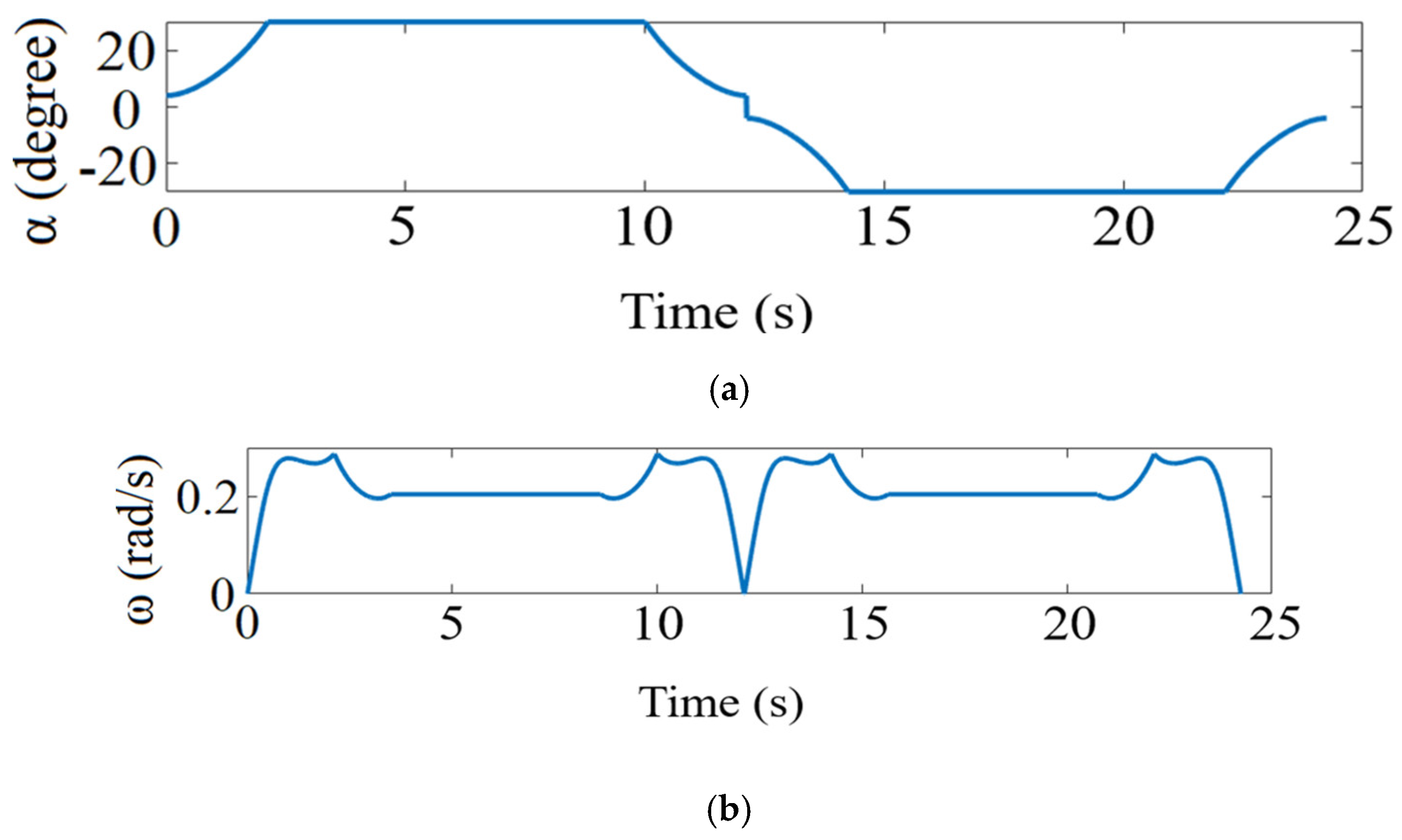
Figure 5. Owing to the symmetrical property, the response of
and
for a round-trip winding are as illustrated in
Figure 6.
- C.
Winding path analysis
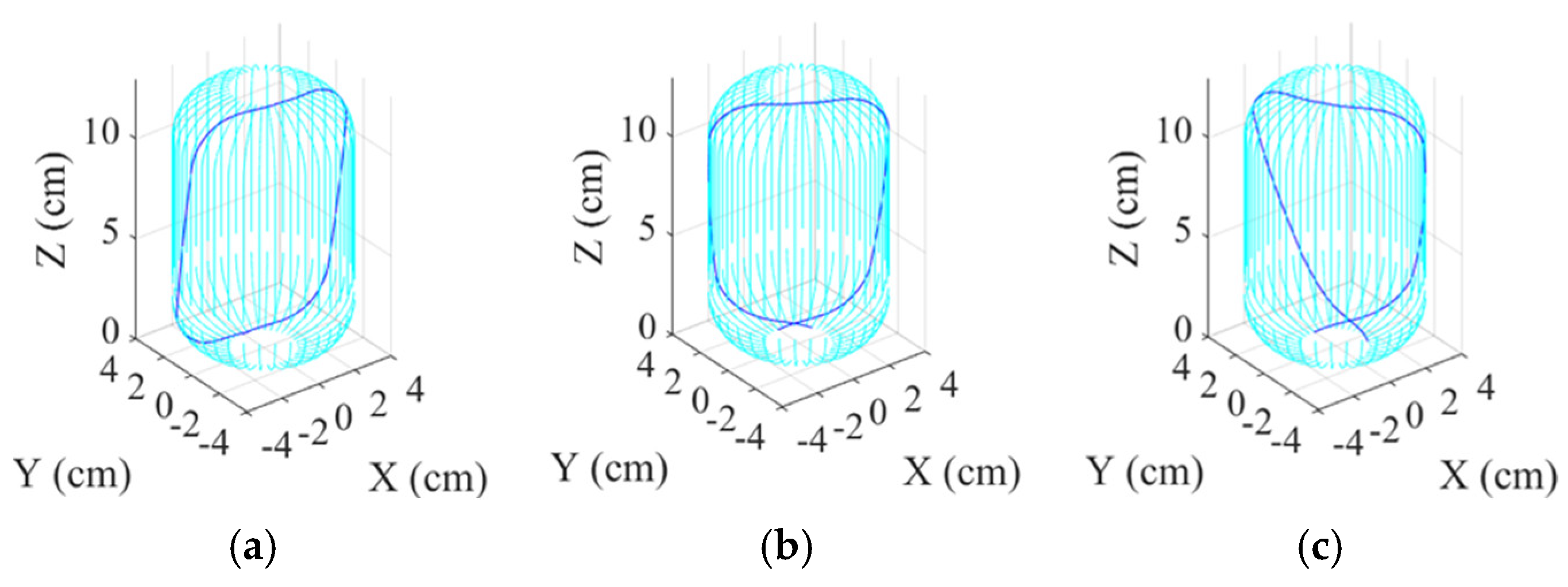
In practical applications, the cylindrical winding angles are between 10° and 40°. For illustrative purposes, the resulting thickness after one complete coverage will be evaluated for each interval of 5°. Based on the cylinder shown in
Figure 2, the round-trip winding path of different cylindrical winding angles are shown in
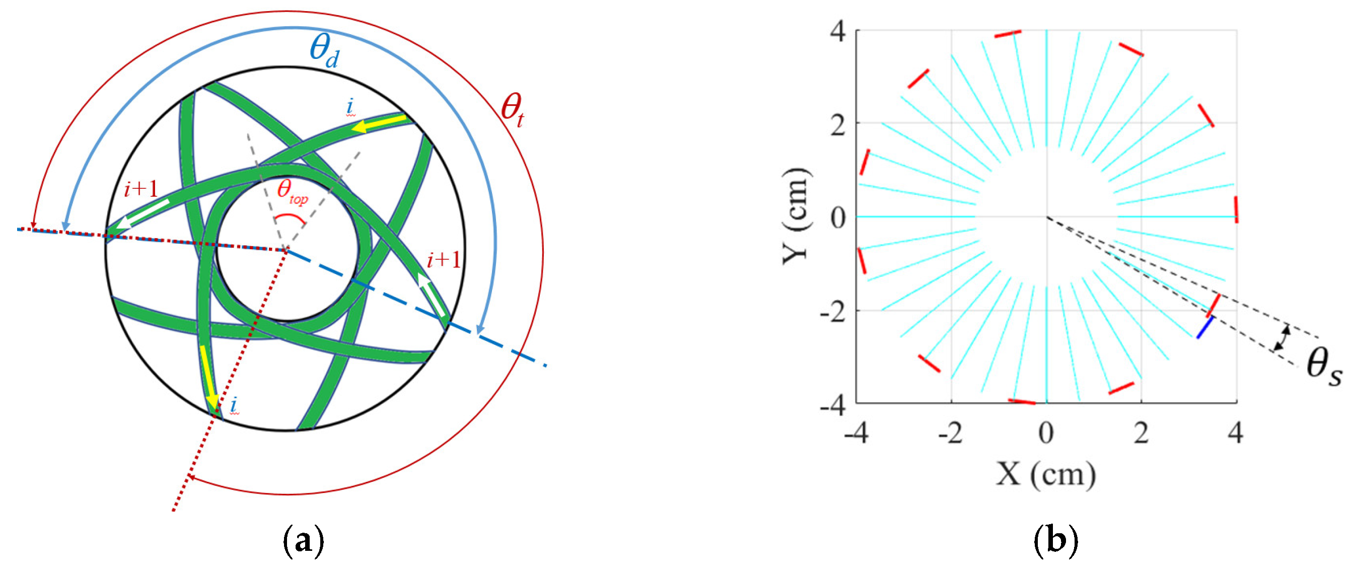
Figure 7. Let
denote the angular position difference between the entering and leaving of filament on cylinder end, and
denote the angular position difference after a round trip winding as shown in
Figure 8 and
Figure 9 It can be obtained that:
Suppose one complete coverage winding comprises m full-cycle windings and one full-cycle winding consists of
i round-trip windings, where
i is determined as the maximum number of round-trip windings without parallel overlapping between filaments. Define
as the angular position difference between the
i + 1 round-trip winding and the first round-trip winding as shown in
Figure 8b, then
can be determined by:
where mod (.) is the remainder calculation. Under relational Equations (21) and (22), the path of one full-cycle winding can be obtained for a given
. The simulation results of the case study are shown in
Figure 10. After completion of a full-cycle winding, the maximum angular position difference can be denoted as
and the overlapping angle of the
i + 1 and the first round-trip winding is
as shown in
Figure 11. Then, the requires number of full-cycle winding to have one full-coverage can be obtained by:
where ceil (.) is the unconditional carry quotient. Subsequently, the total number of round-trip winding (
tw) for one full coverage is:
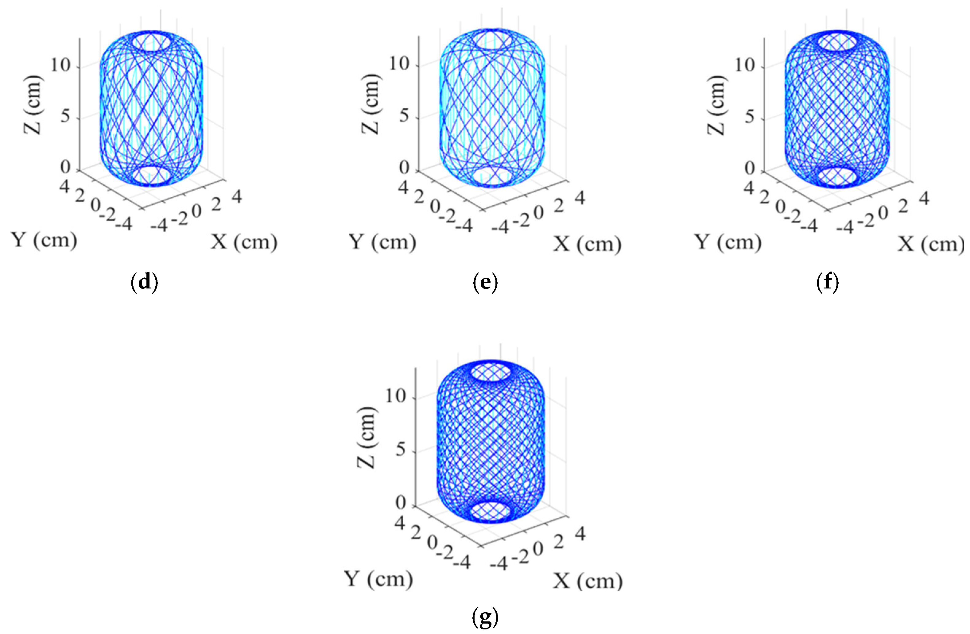
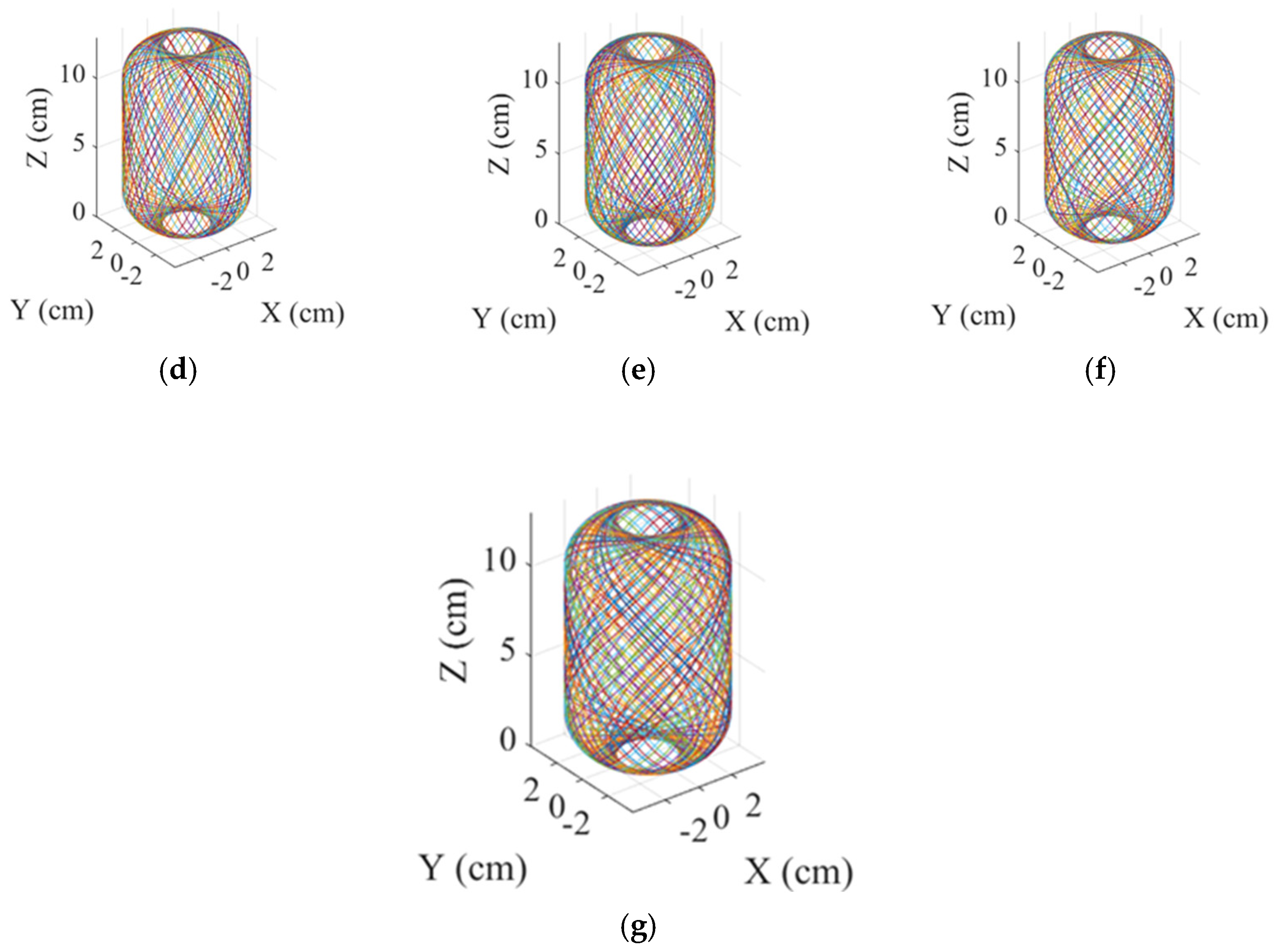
Figure 12 shows paths of one complete winding for different cylindrical winding angles. In
Table 1, it shows the Number of round-trip windings to complete one full coverage with different cylindrical winding angles.
Based on the complete winding path obtained, the distribution of filament thickness can then be analyzed to ensure the required strength of the gas cylinder. The average number of filament layers
on the cylinder surface with cross-section radius
can be determined by:
for the case that the gas cylinder has been wound back and forth
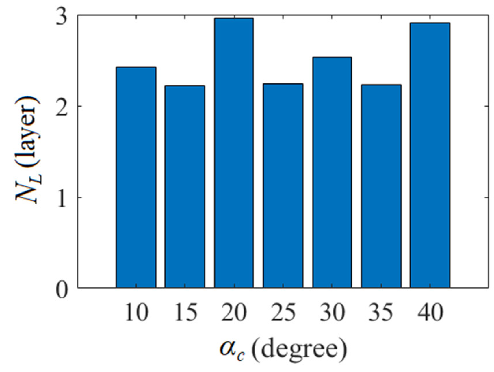
tw times. By Equation (25), the average layers of coverage at the joint ends
=
Yeq with different
are shown in
Figure 13.
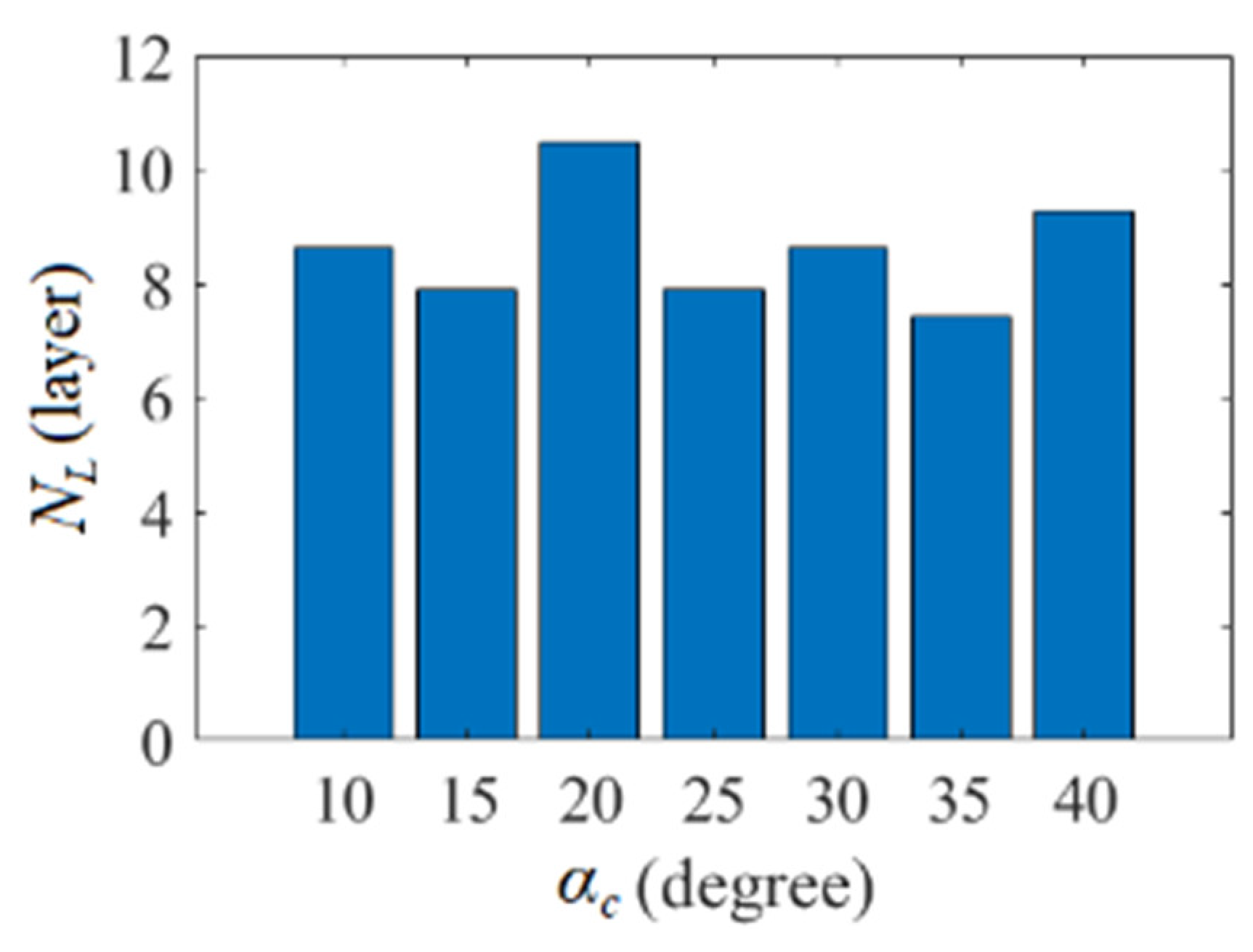
For alignment purposes for subsequent cycles, the last round-trip winding of the prior cycle may require winding extra
at the end circumference with smallest radius; therefore,
NL will be described by
For the study case, the average number of layers at the end of the gas cylinder can be estimated and shown as in
Figure 14.
3. Stress and Strength Analysis of Reinforced Gas Cylinders Wound with Composite
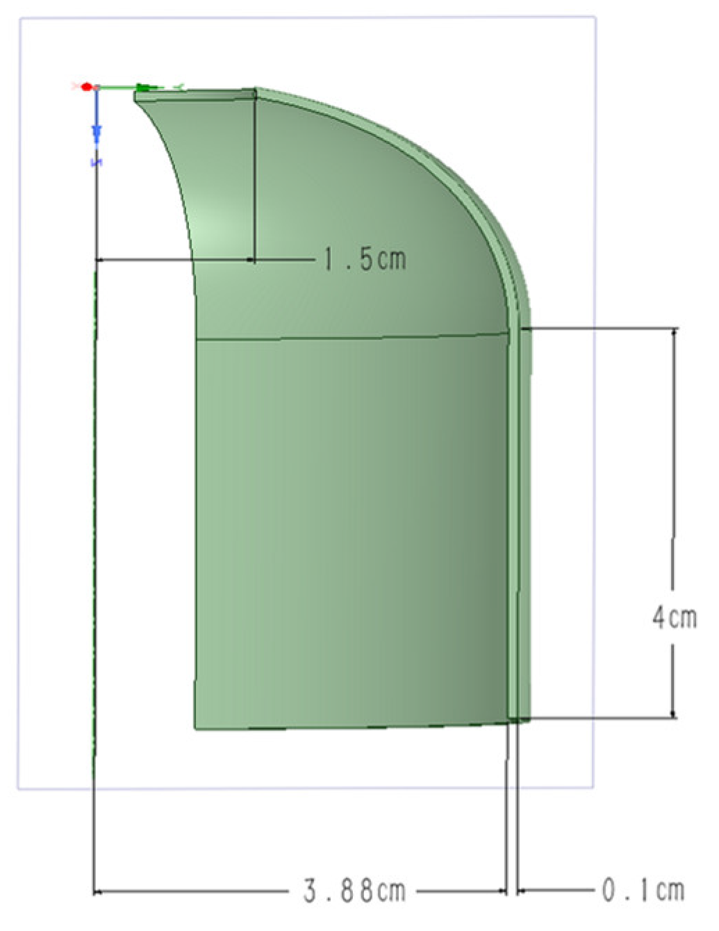
After completion of a full coverage winding, the stress and strength analysis can be carried out to ensure the specifications of the resulting gas cylinder. This study uses the ANSYS software to analyze the stress distribution of gas cylinders. Regarding the structural system, gas cylinders use the structural steel listed in the ANSYS database as the inner material. Take the gas cylinder in
Figure 2 with a thickness of 0.1 cm as an example. A 1/8 model can be used for computational analysis owing to the geometric symmetry of the gas cylinder, as shown in
Figure 15.
For the ANSYS Composite PrepPost (ACP) system analysis, T700 carbon fiber produced by Toray of Japan and EPIKURE 3234 resin is used. The materials data is shown in
Table 2, and the second column of 12 K specifications were used for this study.
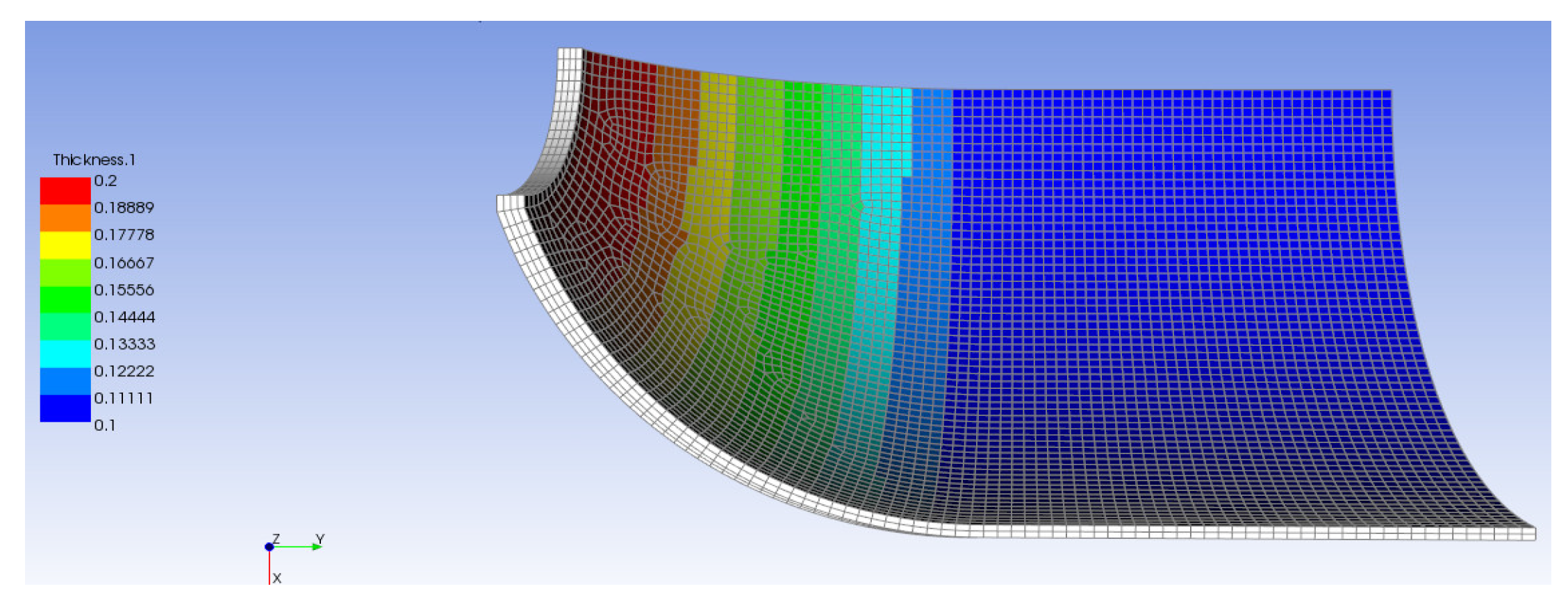
Take the cylindrical winding angle of 30° as an example. For one full coverage winding, the filament will cover the central cylinder surface twice, contributed by one layer with an angle of +30° and the other layer with an angle of −30°. The end cap is also wound at two different angles round-trip, but the winding angles and the number of layers of coverage are determined by Equations (25) and (26). Take the thickness of 0.05 cm for a single layer of composite filament as an example; the thickness distribution of the outer lining by composite materials can be constructed as shown in
Figure 16.
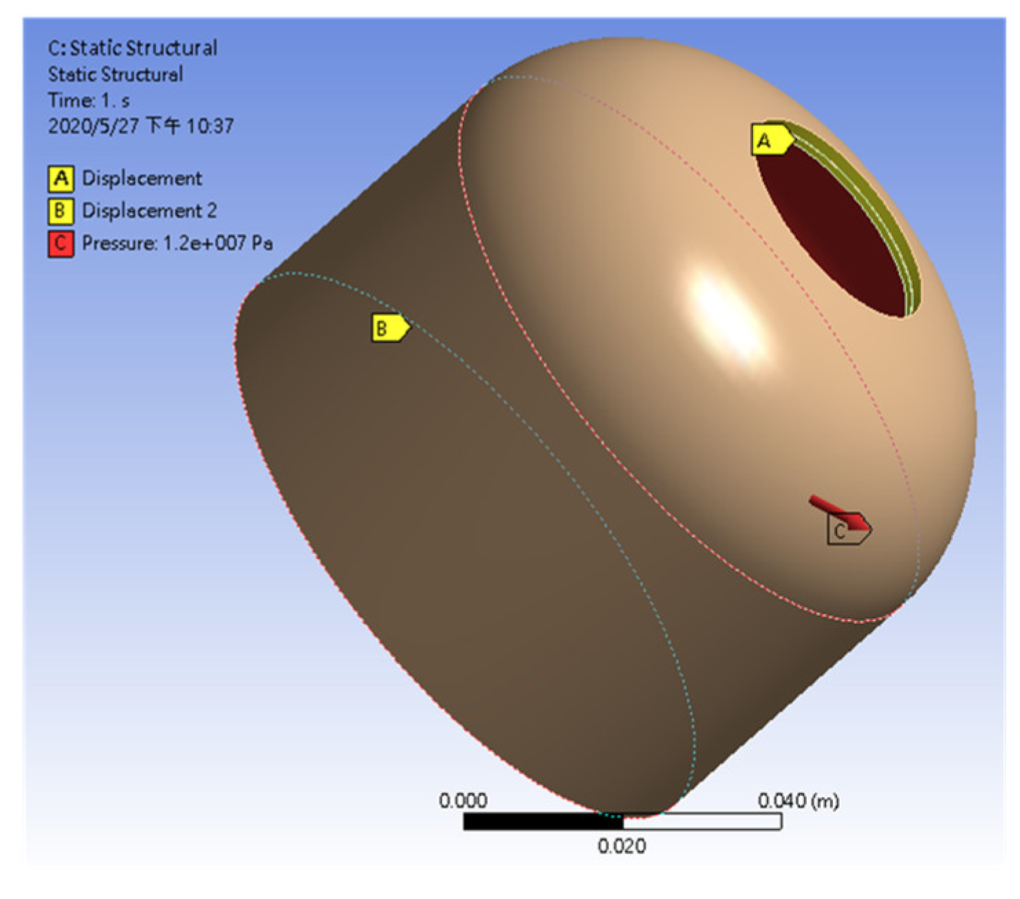
Based on geometric symmetry, the boundary conditions for cross-sections A, B and C, shown in
Figure 17, are described as follows. Cross-section A only arrows a displacement along the Z direction, i.e., it is constrained by ΔX = 0 and ΔY = 0. The fact that the membrane thickness of the cylinder end is much larger than that of the cylinder body and the corresponding strength in X and Y direction is very high should be noted. Cross-section B is the symmetry plane of the cylinder, which only arrows displacement in X and Y directions, i.e., it is constrained by ΔZ = 0. For the gas cylinder to withstand a pressure difference of 120 bar, the face C has the pressure boundary condition of 12 MPa outwards.
By adopting the Tsai-Wu failure criterion [
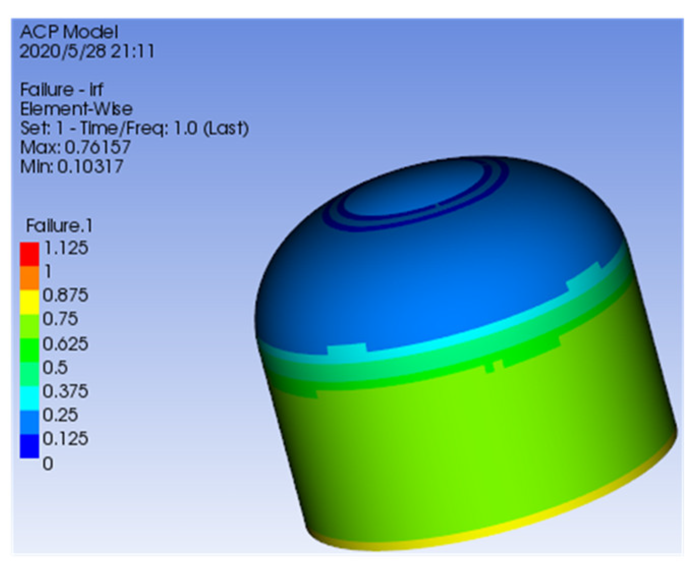
23] for failure analysis, it reveals that after completing one full coverage by carbon fiber, the maximum damage value is 0.76157, as shown in
Figure 18. As the damage values are all less than 1, the filament reinforcement gas cylinder in this example is capable of withstanding pressure up to 120 bar.
A failure analysis of one complete coverage was conducted for cylindrical winding angles of
and the results are shown in
Table 3. It illustrated that all seven winding patterns could withstand the pressure of 120 bar. However, due to the fact that the lateral (secondary axis direction) tensile strength of the carbon fiber composite is much lower than the tensile strength of the primary axis direction, the failure index of the cylindrical winding angle of 10° is closer to 1 than the other.
The winding path of the end cap surface is used to calculate the length of the composite materials by piecewise segmented accumulation. Suppose the length of the composite materials used for round-trip winding is
, the total length
of composite materials required to complete one full coverage winding can be determined by
As shown in
Table 3, the winding path with cylindrical winding angle
= 15° can be implemented with the least composite materials with a maximum failure criterion index of 0.8264 for one full coverage among the seven cases. It should be noticed that failure index is useful for the vessels used just once. However, for a rocket launching mission, high-pressure gas cylinders are considered disposable, and for this, the analysis can be used to reduce the costs associated with trial and error.
Based on the study in
Section 2 and
Section 3, the filament winding reinforcement design procedure for gas cylinders is summarized as follows.
Determine the geometric parameters of the gas cylinder, including the diameter, the length of the cylinder, and the required withstanding pressure;
Design the end cap surface geometry based on the withstanding pressure of the cylinder, the geodesic description system, and the composite stress matrix combination;
According to the maximum static friction conditions, select the cylindrical winding angle and determine the number of coverage layers required for the cylinder by stress and strength analysis;
Realization of path and motion planning based on the winding pattern obtained in step 3. Subsequently, the motion commands for each machine axis can be determined, which will be described in the next section;
Carry out motion control for each motion axis to complete filament winding.
4. Planning and Realization of Motion Paths of Four-Axis Filament Winding Machine
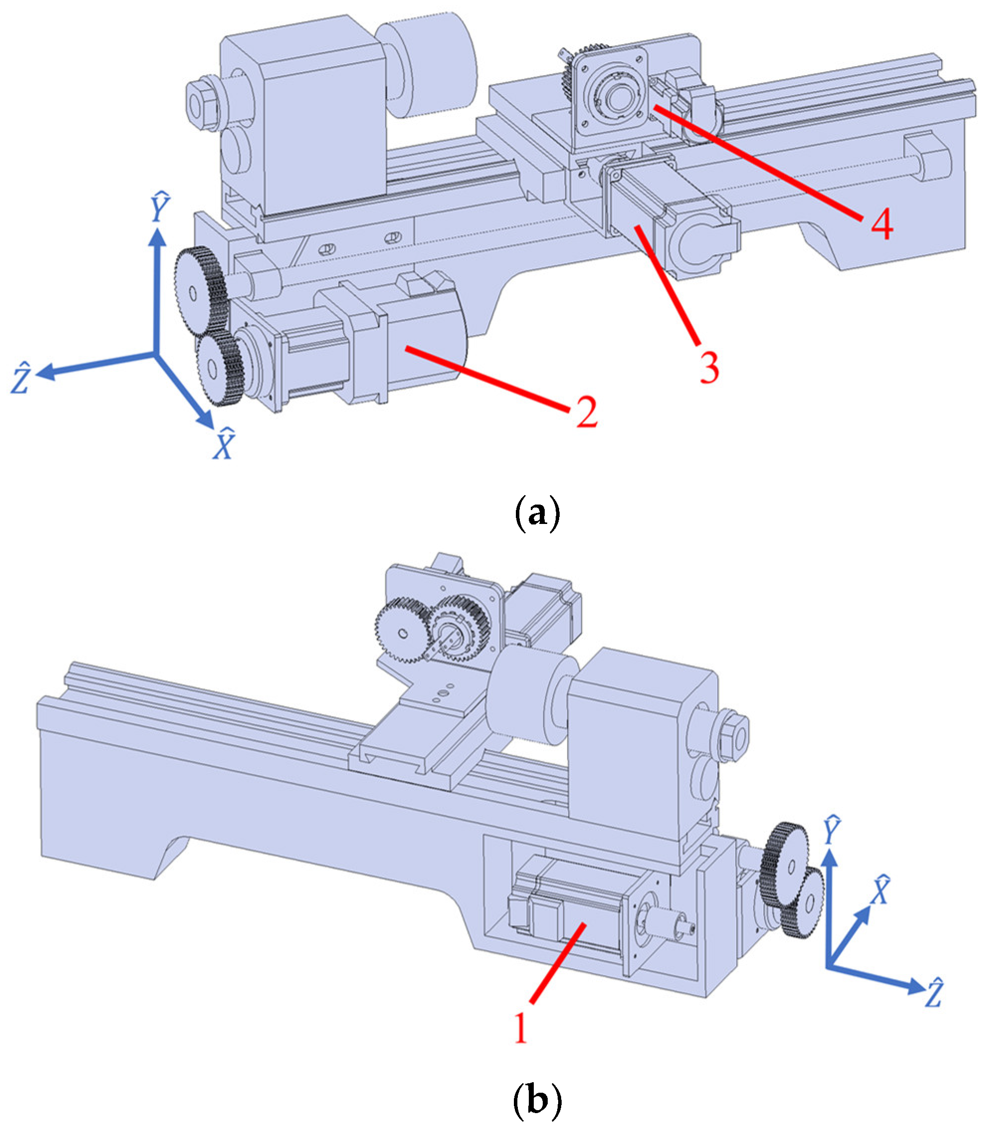
In this section, a four-axis winding machine, as shown in
Figure 19, will be applied to perform the winding process. The motion axes geometry and their physical arrangement will be described in association with the winding motion. Implementation of real-time motion control will also be demonstrated to conduct the winding procedure.
The machine is organized to carry out filament winding for gas cylinders by adding an extra motion axis to a three-axis lathe. Translational motions along the axis (short) and axis (long) are performed by motor 3 and 2, respectively. The rotational motions of the axis are driven by motor 4, and gas cylinder will be mounted along axis and driven by motor 1 for the required cylinder rotating speed .
- A.
Motion control design
Since the
-axis is the primary axis of the gas cylinder, its angle of rotation during the winding is the angle of rotation of the winding coordinate system
. It can be obtained by the integral of the rotational speed
of the gas cylinder. During a round-trip winding, the forward and return paths require the same amount of angular motions of
. Based on the proposed approach in
Section 2 (b) and
= 15°, the time response of
relative to one round-trip winding can be illustrated as in
Figure 20.
The rotation axis of the
-axis (
) controls the rotation of the winding head. During the winding of the end cap, the angular displacement is obtained through the geodesic principle
, where
and
is the instantaneous radius and geometric constant of the end cap, respectively. For the cylindrical winding angle of 15° and
Yeq =
R = 4 cm,
cd = 1.0353 can be obtained, and
for one round-trip winding can be obtained, as shown in
Figure 21.
To avoid direct contact with the cylinder surface, the winding head moving in
plane will keep 0.5 cm from the cylinder in this illustration. Under a fixed winding radius, the position of the winding head on the
axis during one complete winding is constant. Since
R = 4 cm and thickness incensement is insignificant during one round-trip winding, the time response of the position along
-axis will be kept constant as shown in
Figure 22.
The relative position from the contact end point to the winding head roller can be represented by
, its vector components to the
,
, and
can be obtained by the angle
between the
-axis and the
-axis, the angle
between the
-axis and the
-axis, and the angle
between the
-axis and the
-axis, as shown in
Figure 1. Based on the coordinate transformation described Equations (5) and (6), and assuming that the distance between the instantaneous contact end point on the cylinder and the winding head is of magnitude
dt, and its component in the
direction is
dz, then the position of the winding head roller in the winding coordinate system
can be described in coordinate
as:
By the constraint relations, it can be obtained that:
Therefore, the position of the winding head roller that moves along the
-axis direction can be obtained by adding
dz to the
-direction component of the contact endpoint. The time response of the winding head roller can then be obtained, as shown in
Figure 23 for the demonstrated case.
- B.
Realization of four-axis motion control
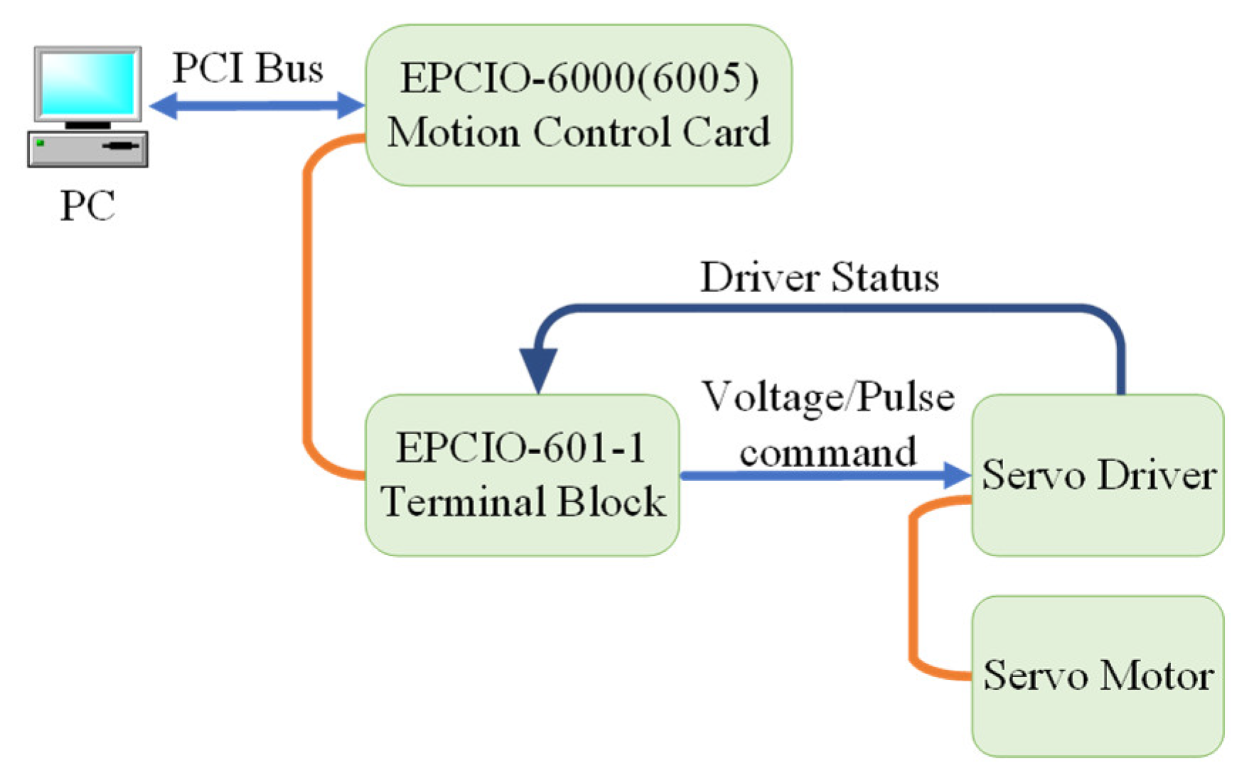
The four-axis motor of the filament winding machine is driven by the motion control interface card through the PCI port of the computer, as shown in
Figure 24, such that the motor follows the generated command shown in
Section 4 (A).
The Visual Studio C++ was applied as the development environment of the axis motion control interface card and control software. Because the EPCIO driver card can only execute integer pulse commands, continuing to use unconditional carry or round down of the position commands will cause significant cumulative errors. Therefore, in addition to adopting the rounding method, the error caused by rounding up or down must be temporarily stored. When the accumulated value reaches a prescribed threshold, the accumulated integer will be added to the following pulse command of DDA_Time as motion compensation.
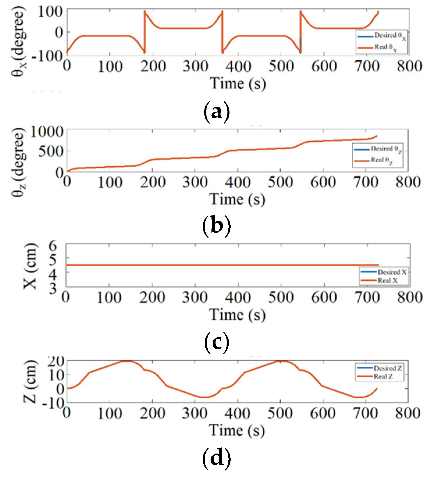
Figure 25 shows the desired and resulting motion response, and
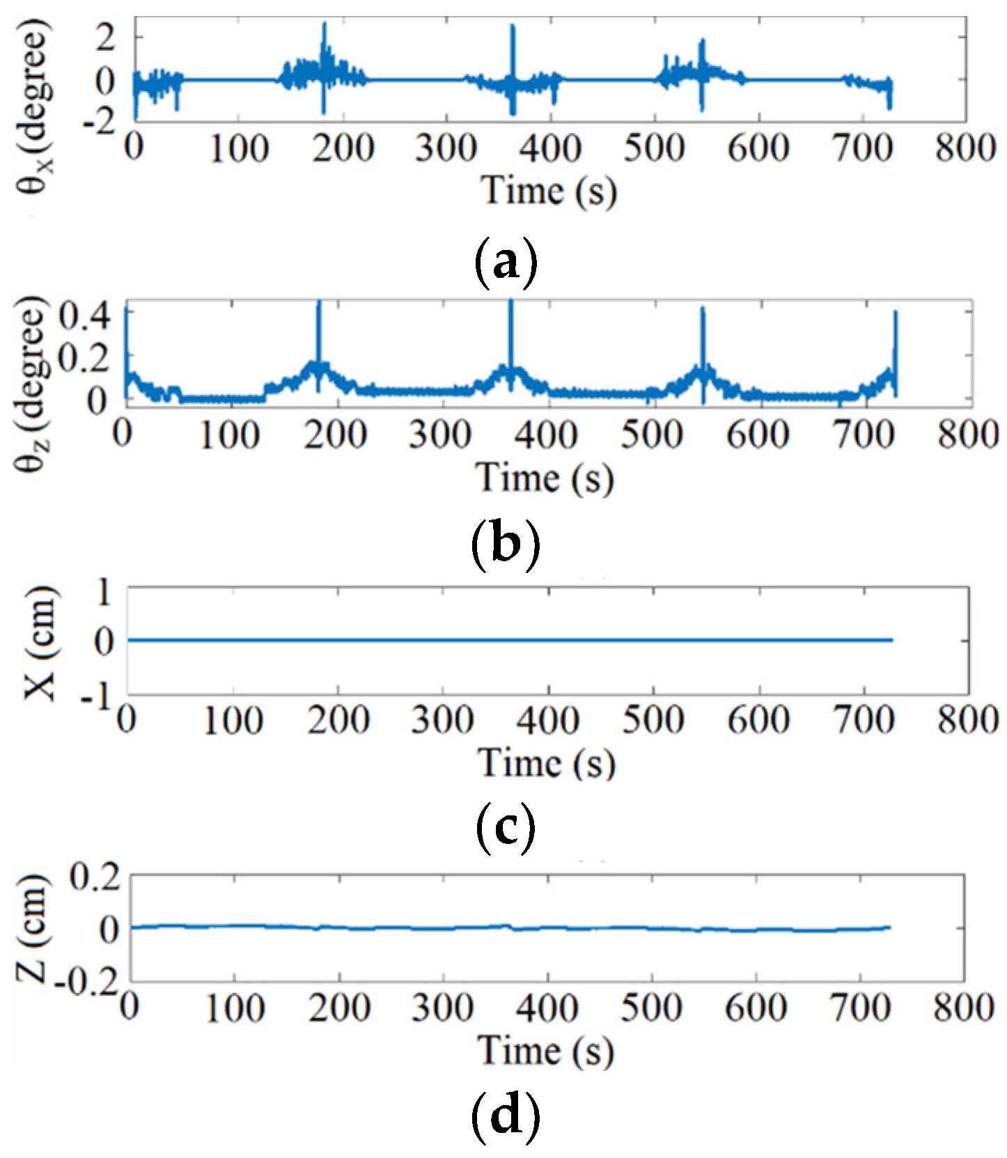
Figure 26 shows the error response of the four-axis motion for two round-trip winding. The error can be adjusted by the prescribed threshold and its influence on winding will be limited due to the usage of absolute position reference command instead of incremental type.
Figure 27 demonstrates the winding result during two round-trip windings in practice.
