Article

Analysis and Optimization of Milling Deformations of TC4 Alloy Thin-Walled Parts Based on Finite Element Simulations

School of Advanced Manufacturing Engineering, Chongqing University of Posts and Telecommunications, Chongqing 400065, China
*
Author to whom correspondence should be addressed.
Machines 2023, 11(6), 628; https://doi.org/10.3390/machines11060628
Submission received: 7 May 2023 / Revised: 31 May 2023 / Accepted: 2 June 2023 / Published: 6 June 2023
(This article belongs to the Special Issue Recent Progress of Thin Wall Machining)

Abstract

:
TC4 (DIN3.7164/5) alloy thin-walled parts are widely used in aviation and aerospace industries. However, due to their special structure, shape and poor machinability, large milling forces and milling deformation often occur in the milling process, which cannot guarantee the machining quality and accuracy. The milling processing parameters and milling geometric parameters have a significant impact on the milling force and the deformation, and optimization of the influence factors of milling deformations is important for milling quality. Considering that performing milling experiments under multiple conditions is often costly and time-consuming, this paper provides a finite-element-simulation-based method to study effects of the factors on the forces and deformations during milling thin-walled parts. Firstly, using ABAQUS, a finite element simulation model of the milling process of thin-walled parts is established. Additionally, an orthogonal experimental scheme is designed for optimization of the milling parameters, so as to determine the optimized experimental scheme, and then the optimized experimental scheme is verified to reduce the milling force and deformation by finite element simulations. The optimal parameters for a minimal milling force are a spindle speed of 2000 r/min, a feed rate per tooth of 0.04 mm/z, a milling depth of 1.6 mm, a milling width of 1 mm, a diameter of 6 mm, a rake angle of 20°, a tilt angle of 45°, and two teeth. Similarly, the optimal parameters for minimal node deformations are a spindle speed of 4800 r/min, a feed rate per tooth of 0.18 mm/z, a milling depth of 1 mm, a milling width of 1 mm, a diameter of 16 mm, a rake angle of 20°, a tilt angle of 40°, and four teeth. In addition, this paper uses an optimization algorithm to fit the empirical function with a certain practical value, which can provide a reference for the machining of TC4 titanium alloy. By doing so, we can optimize the milling parameters to obtain the desired machining quality and accuracy, while also saving on time and resources.

1. Introduction

Titanium alloy materials are highly desirable in aerospace and marine applications due to their high specific strength, light weight, and good corrosion resistance. However, their poor thermal conductivity and the high milling processing temperatures can lead to serious tool wear, which in turn affects the stability of milling processing and compromises the quality of processing. Additionally, the thin walls, low strength, and poor rigidity of titanium alloy thin-walled parts make the milling process susceptible to multiple factors, including the milling processing parameters and the mill geometry parameters, making it difficult to ensure machining accuracy. In this paper, we employ the method of orthogonal analysis and the technology of finite element simulations to investigate the influence of different milling processing parameters and mill geometry parameters on the milling deformation of titanium alloy thin-walled parts. By summarizing the influence law, we establish an empirical function of the milling processing parameters and mill geometry parameters, which allows us to reasonably select milling parameters and improve the milling accuracy of titanium alloy thin-walled parts. This work has important theoretical significance for the field of milling and provides practical guidance for the optimization of milling parameters in the processing of titanium alloy thin-walled parts.
The milling force is one of the main factors to evaluate the quality of the milling process. At present, many scholars at home and abroad have devoted themselves to research on the establishment of a prediction model of the milling force of titanium alloy thin-walled parts. For example, Ge et al. [1] used a five-factor and five-level orthogonal experimental method to conduct milling tests on titanium alloy thin-walled parts, studying the influence of milling processing parameters on the milling force through the range analysis of the milling force, establishing the model of the milling force of titanium alloy thin-walled parts, and verifying the accuracy of the model. Hu et al. [2] obtained a prediction model of the milling force of titanium alloy under a specific machining environment after analyzing and processing a large amount of milling test data based on the response surface method and orthogonal tests. The regression effect of the prediction model was highly significant through an ANOVA, indicating that the prediction model is effective in predicting the milling force in the range of common milling parameters. Tang [3] established a neural network model for milling force prediction by using a regularized fuzzy neural network learning algorithm, and the results show that the TC4 milling force prediction model established by the regularized fuzzy neural network method is reliable. The change in the milling force, which is intuitively reflected on the thin-walled parts of titanium alloy, resulted in the deformation of the thin-walled parts during the milling process, which is also the actual physical quantity that needs to be considered in real applications. At present, research on the establishment of a deformation prediction model of titanium alloy thin-walled part milling, such as work by Qian [4] on titanium alloy thin-walled linkage rings as the object, has launched research on machining process, milling force modeling, deformation prediction, etc., and established the prediction model of titanium alloy thin-walled parts milling deformation of the inner hole and cutting process machining deformation prediction models. By means of theoretical analyses and finite element simulations, Pan [5] studied the deformation of T-shaped and L-shaped titanium alloy thin-wall parts after machining and studied the influence of the milling speed on the deformation of a T-shaped workpiece. Gao et al. [6] studied the deformation, burr height, and size errors in the milling process of thin walls with T-shaped micro-curved surfaces through a finite element analysis in order to meet the machining quality requirements of thin-wall structures with micro-curved surfaces, proving that the interaction between key milling parameters cannot be ignored and establishing a mathematical model of burr height and size errors. The above-mentioned researchers focused on the influence of milling processing parameters or mill geometry parameters unilaterally on the milling force or deformation when studying the influencing factors or empirical formulas related to milling, and there is still a lack of research on the comprehensive influence brought by the overall parameters of milling.
In order to improve the machining quality of titanium alloy thin-walled parts, the optimization of milling process parameters is crucial, since these parameters have a significant impact on milling deformation and machining quality through their effect on the milling force. Thus, numerous domestic and foreign scholars have conducted research on the optimization of milling process parameters for thin-walled titanium alloy parts. For instance, Yan et al. [7] optimized key processing parameters such as the spindle speed, milling depth, and feed rate, with the material removal rate, tool life, and thickness of the residual stress layer as the optimization objects. Li et al. [8] proposed a multi-objective optimization method based on the combination of a response surface method and a weighted gray correlation analysis for the optimization of milling parameters in the process of milling. Doriana et al. [9] optimized the milling parameters in the turning process based on a genetic algorithm and obtained the best combination of milling parameters. Shen [10] established a milling parameter optimization model with the spindle speed and feed rate as the design variables and the maximum milling deformation as the minimum objective function, calculating machining deformation by using a finite element method and optimizing the milling parameters of a thin-walled shell of a titanium alloy helmet scanner by using a particle swarm optimization algorithm. Yue et al. [11] established a finite element simulation model for the milling process of thin-walled circular titanium alloy parts using the finite element simulation software ABAQUS, obtained the changes in the stress field and temperature field under different milling parameters through simulations, and optimized the milling parameters by combining orthogonal tests with a multi-objective genetic algorithm, which proved that the optimized milling parameters improved the milling. Ilesanmi et al. [12] used computer-aided modeling and simulation tools to determine the geometric effects of indexable double-sided round carbide milling cutters on the surface roughness of titanium alloys during milling; modeled; iteratively simulated the tool geometry tilt angle, number of slots, and wedge angle; and generated the most feasible combination of cutting tool geometry and cutting parameters based on the obtained results to obtain the minimum surface roughness. Hu et al. [13] considered the application of variable helical end mills to the study of titanium alloy milling, established the kinetic equations of variable helical end mill milling, derived a prediction model of milling force for variable helical end mills, and obtained the instantaneous milling force and its variation law by solving the above-mentioned equations. Most of the above research on milling parameters just focused on the optimization of the milling parameters without fitting specific equations to them, so there are many inconveniences in practical applications. An empirical function prediction model is an excellent vehicle to help apply research in practice.
This paper utilizes finite element simulation technology and orthogonal testing to predict the milling force and machining deformation corresponding to different machining and tool parameters. Through an extreme difference analysis, the optimal combination of machining parameters that minimize the milling force and deformation of thin-walled titanium alloy parts is determined from the multiple parameter combinations. Additionally, empirical functions for the milling force and machining deformation based on the milling and tool parameters are established through an optimization algorithm. The research results are transformed into convenient application formulas, which can provide important guidance for the selection of milling parameters.

2. Milling Analysis of TC4 Alloy Thin-Walled Parts

2.1. Analysis of Factors Influencing the Milling Deformation of Thin-Walled Parts

TC4 (DIN3.7164/5) alloy thin-walled parts often exhibit characteristics such as complex structures, large sizes, low stiffness, etc. [14]. Consequently, machining deformations are likely to occur during the machining process. Figure 1 summarizes the factors that influence the processing deformation of thin-walled parts.
In the actual milling process, factors such as the machine tool and clamping system have little influence on the milling force and deformation of thin-walled parts in the milling process. Considering the complex number of factors involved, this paper selects eight parameters that have a great influence on the milling of thin-wall parts for combined research. The selected parameters are the spindle speed n, the feed per tooth f, the milling depth ap, the milling width ae, the diameter of the milling cutter d, the rake angle of the milling cutter γ, the tilt angle of the milling cutter λ, and the number of teeth z. The reasons for choosing the parameters are given below.
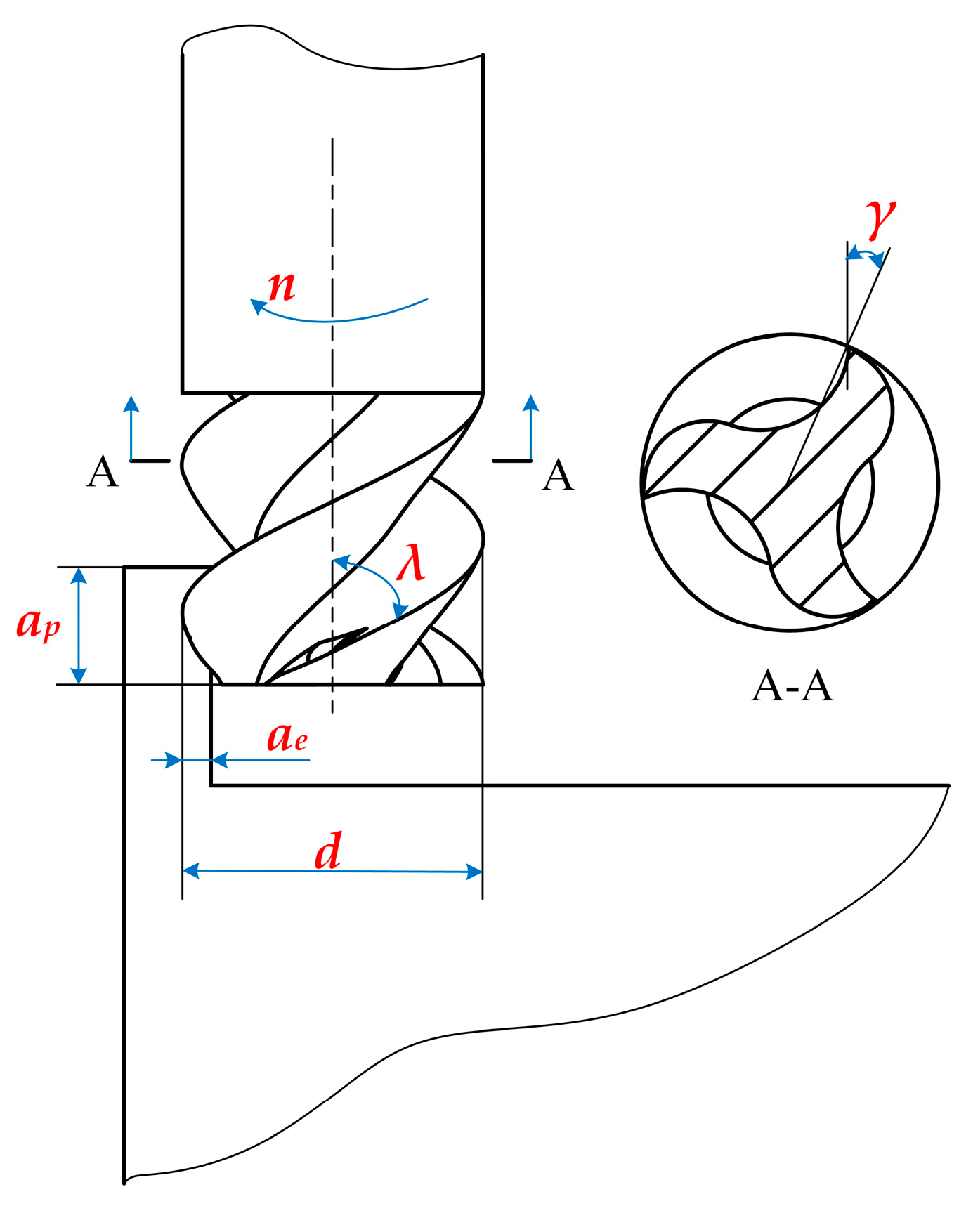
  • The influence of the milling cutter
The tool material, wear conditions, and geometry parameters all have an impact on part deformation during the machining process. The higher the stiffness of the tool material, the better the milling performance. A good wear resistance can improve the machining surface quality, reduce tool wear, and prolong tool life. The geometric parameters of the tool mainly include the diameter, the number of cutting edges, the front and rear angles of the milling cutter, the tilt angle, the radius of the cutting edge, etc. The influence of these parameters can be summarized as follows: Increasing the front angle reduces the milling force, while a large rear angle improves the durability of the tool. However, excessively large front and rear angles can weaken the milling edge and reduce the tool’s life, while also worsening the heat dissipation conditions. A larger tilt angle results in a longer contact length between the workpiece and the milling edge, increasing the load per unit length of the milling edge. The higher the number of milling cutter edges, the better the rigidity of the cutter, but chip accumulation may occur, which can affect the processing quality. The radius of the cutting edge directly affects the cutting pressure, which is one of the most important factors affecting the amplitude of the milling force. Therefore, a reasonable choice of the tool’s front angle, back angle, tilt angle, diameter, and number of teeth can effectively reduce the milling force and milling temperature, reduce milling deformation, reduce the impact during milling, improve the smoothness of machining, prolong the tool’s life, and improve the surface finish quality [15].
2.
The influence of processing conditions
In an actual machining process, milling forces and milling deformations are closely related to different machining conditions. The basic milling parameters include the feed speed vf, milling depth ap, milling width ae, and feed rate per tooth f. The feed speed vf refers to the relative displacement of the workpiece and tool in the feed direction per unit time. The relationship between feed speed vf (mm/min), spindle speed n (r/min), feed rate per tooth f (mm/z), and the number of teeth z is as follows:
v f = n × f × z
From Equation (1), it is clear that the feed speed is positively related to the spindle speed when the feed per tooth and the number of milling cutter edges are kept constant. Therefore, different combinations of machining parameters such as the spindle speed n, feed rate per tooth f, milling depth ap, and milling width ae will have different effects on the milling force and deformation. The optimal combination of parameters can reduce the load of the milling force, reduce the deformation of thin-walled parts, meet the accuracy requirements, and improve the machining efficiency.
3.
The influence of milling force
Due to the low stiffness of thin-walled parts, they are prone to elastic deformation under the influence of milling forces. As a result, their actual milling width differs from the theoretical milling width, causing some materials to not be removed compared to the ideal situation. Moreover, after the tool has passed through, the balance of forces is disrupted, resulting in the redistribution of residual stresses in the thin-walled part and causing elastic partial rebound, ultimately leading to processing deformations [16].
In addition to the influence of the milling force on machining deformations, there are many factors that affect the deformation of thin-walled parts. For example, the machine tool’s own error will cause large deformations, and an insufficient positioning accuracy of the clamping system leads to large deformations. The absence of cooling and lubrication conditions can lead to enhanced collisions, leading to large deformations. The processing sequence and the temperature generated during processing can reduce deformations. In summary, machining deformations are influenced by complex factors, among which the main machining parameters, such as spindle speed n, feed per tooth f, milling depth ap, and milling width ae, and the primary geometry parameters of the milling cutter, such as the diameter, number of teeth, rake angle, and tilt angle, have the most significant impact.

2.2. Proposed Empirical Model for Milling

Due to the numerous and diverse factors that affect thin-walled TC4 alloy parts, studying all the action laws and influence degrees would be an enormous task. Therefore, Ge et al. designed and conducted physical orthogonal tests on TC4 alloy thin-walled parts to determine more realistic milling force models and milling coefficient parameters. Subsequently, they derived empirical equations for milling forces using an average rigid force model [17]. The milling force given in Equation (2) is the sum of the milling forces borne by the milling cutter during the milling process.
F = C F a p x F f y F v c n F K F ,
where CF is the coefficient to be determined, which is related to the workpiece material and milling tool type; ap is the milling depth; f is the feed; vc is the milling speed; KF is the correction factor; and x F , y F , n F are the coefficients to be determined.
In the various subsequent experiments on thin-walled parts of TC4 alloy, it is observed that the factor magnitudes of the milling factors differ under different machining conditions, but they yield the same form of the empirical value of the milling force equation.
In this paper, we investigate the maximum node deformation resulting from different milling conditions, while taking into account the interactions between milling parameters. Referring to the prediction model used by Gao et al. [6] to fit dimensional deformations, an empirical equation for the maximum nodal deformation is derived, as shown in Equation (3):
S = c 0 + c 1 n + c 2 f + c 3 a p + c 4 a e + c 5 d + c 6 γ + c 7 λ + c 8 z + c 9 n f + c 10 f a p + c 11 a p a e + c 12 a e n + c 13 f a e + c 14 n a p + c 15 d γ + c 16 d λ + c 17 d z + c 18 γ λ + c 19 γ z + c 20 λ z

2.3. Principle of Finite Element Model for Milling Thin-Walled Parts

With the development of finite element simulation technology, the simulation results of finite element simulation have shown high agreement with the actual experimental results. Therefore, its application in the field of metal milling processing has increased. By using the finite element simulation results instead of the traditional test cutting experiments, not only can the milling process be visually demonstrated, but simulation data such as milling processing deformation, milling force, and stress–strain distribution can also be obtained, which is important for further theoretical research. Defining the correct parameters for the key techniques of finite element simulation is essential to ensure the accuracy of the simulated results. These key techniques include the constitutive model for material, chip separation guidelines, failure guidelines, etc. [18]. In this paper, we use the finite element simulation software ABAQUS v6.16 to simulate the milling process of TC4 alloy thin-walled parts in three dimensions. We establish a finite element model of milling force and milling deformations and input different combinations of milling parameters to provide a basis for optimization parameter selection. The finite element simulation process of the TC4 alloy thin-walled parts milling process is shown in Figure 2.

2.3.1. Constitutive Model for Material

The TC4 alloy material is characterized by a high specific strength, a low stiffness, a high strain, and a high strain rate and is susceptible to deformation during the actual milling process due to high temperatures, high milling forces, etc. Therefore, in this paper, the Johnson–Cook constitutive model is adopted to define material properties. The expression for this model is given by [19]:
σ = [ A + B ε n ] [ 1 + c I n ( ε ˙ ε ˙ 0 ) ] [ 1 ( T T r T m T r ) m ] ,
where A, B, c, n, and m are material constants; Tm is the material melting point; Tr is room temperature; and ε is the strain.
According to ref. [20], the Johnson–Cook parameters of the TC4 alloy material are shown in Table 1. To integrate this Johnson–Cook constitutive model into the finite element stimulation model built in the finite element simulation software ABAQUS v6.16, we filled the parameters of Table 1 in the corresponding positions when editing the material.

2.3.2. Failure Guidelines

Milling is a continuous material removal process, which is represented in the finite element simulation as unit deletion. The Johnson–Cook damage model can accurately reflect the failure mechanism of TC4 alloy material. Thus, this paper adopts the Johnson–Cook damage model to describe the failure criterion of TC4 alloy and its damage parameter expression [21]:
ω = j = 1 n Δ ε p l ¯ ε D p l ¯ ,
where Δ ε p l ¯ is the equivalent plastic strain increment and ε D p l ¯ is the failure strain. When ω > 1, the material reaches the failure limit and fails to fracture and the mesh fails and is removed. The expression of the failure strain ε D p l ¯ is:
ε D p l ¯ = [ d 1 + d 2 exp ( d 3 σ p σ min ) ] [ 1 + d 4 I n ( ε ¯ ˙ ε ¯ ˙ 0 ) ] [ 1 + d 5 ( T T r T m T r ) ] ,
where ε ¯ ˙ 0 is the reference strain rate; ε ¯ ˙ is the plastic strain rate; σ p is the compressive stress; σ min is the von Mises stress; and d1, d2, d3, d4, and d5 are the dimensionless parameters for the failure of TC4 alloy material as shown in Table 2. Additionally, we chose the Johnson–Cook damage for ductile metals in the the finite element simulation software ABAQUS v6.16 directly when editing the material of the finite element simulation model, and then we filled the Johnson–Cook failure parameters of Table 2 in the corresponding positions, which integrates the Johnson–Cook damage model into the finite element simulation software ABAQUS v6.16.

2.3.3. Chip Separation Guidelines

During the milling process, material undergoes deformation and separation and the chip separation criterion is needed to simulate chip formation and separation [23]. In this study, a combination of energy and displacement is chosen as the chip separation criterion. The displacement method is based on whether the relative positions of the tool tip and the unit node in front of the tool tip have changed to reflect whether the chips are separated. The unit fails when D > 1, and the criterion is given by:
D = υ p l ¯ υ f p l ¯ = υ p l ¯ L ε f p l ¯ .
Using energy as the chip separation criterion, the failure of a unit occurs when D > 1, which can be expressed as:
D = 0 u σ ¯ d u p l ¯ G f G f = 1 υ 2 E K 2 ,

3. Finite Element Simulation Tests

3.1. Orthogonal Experimental Design for the Milling of Thin-Walled Parts

Through representative experiments, the orthogonal experimental method can evaluate the impact of each orthogonal factor on the results, determine the order of influence, and obtain the factor combination for the relatively best results [24]. There are many influence parameters in the process of optimizing the milling deformation. When using conventional experimental methods, there will be an enormous amount of experimental work. Therefore, this paper employs the orthogonal experimental method to study the impact of each influence parameter of milling deformation with less experiment work.
To reduce the milling deformation and milling force, a finite element simulation model of the milling process of TC4 alloy thin-walled parts is established in the finite element simulation software ABAQUS v6.16, and the orthogonal experimental scheme is designed in this paper. By a range analysis of the orthogonal experimental results, the influence law of each parameter on the milling force and milling deformation have been summarized, and the best parameter combination for the minimum milling deformation and milling force has been obtained in this paper.
To achieve high-quality experimental results, it is essential to make a reasonable approximation of the experimental parameters. Considering the real-world situation, the factors and levels for the orthogonal experiments are determined and are presented in Table 3. Accordingly, the orthogonal table is designed as shown in Table 4 (L64 3 × 4 × 6 × 85). These factors are shown in Figure 3.

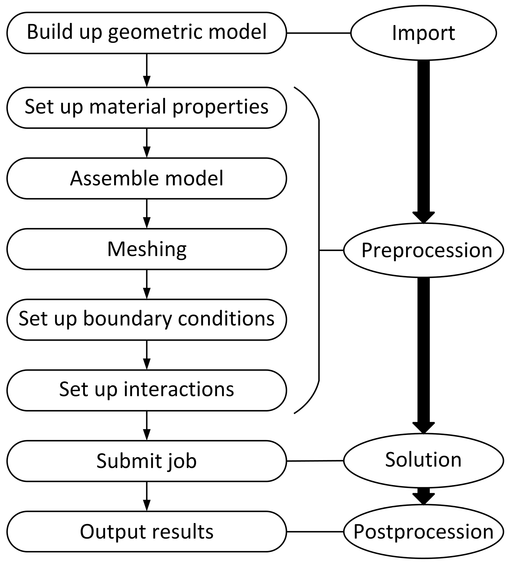
3.2. Establishment of the Finite Element Simulation Model

In the finite element simulation model established in this paper, the tool is a solid carbide end mill, and the milling geometric parameters are shown in Table 5.
According to ref. [14], thin-walled parts usually refer to parts with a ratio of the wall thickness to the axial or radial dimension greater than 1/10. The purpose of this paper is to explore the value of the milling force and the maximum node deformation caused by the thin-walled parts in one single milling process, without paying attention to the final thickness of the milled thin-walled parts. When conducting simulation experiments, different parameter values are selected based on the orthogonal experimental design scheme. A geometry model of the solid carbide end mills is shown in Figure 4. The overall geometry dimensions of the thin-walled part are a length of 170 mm, a width of 100 mm, and a height of 50 mm, while the thin-walled part itself has a length of 170 mm, a width of 4 mm, and a height of 15 mm.
When establishing the finite element model, the milling cutter is set up with a rigid body and the influence of temperature on the thin-walled part in the milling process is not considered. The element shape is quad-dominated and the algorithm used when meshing the milling cutter is advancing front. The element shape is Hex and the technique used is structured when meshing the thin-walled part. In addition, the global size is set as 0.0016 mm when controlling the mesh size of the milling cutter, and the element size is set as 0.002 mm when controlling the mesh size of the thin-walled part. To reduce the computational complexity of the model, the other section’s element size is bigger than the thin-walled section. All element types are set as linear explicit elements and all meshes were appropriately chosen by verifying the mesh in the finite element simulation software ABAQUS v6.16. The final geometry assembly and meshed models of the milling cutter and thin-walled part are shown in Figure 5.

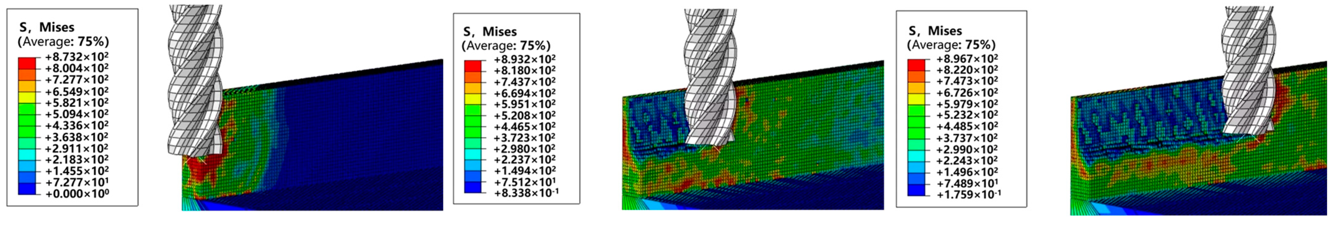
3.3. The Results of the Finite Element Simulation

After conducting finite element simulations with different milling processing parameters and geometric parameters of the solid carbide end mills, the results of total milling force and the maximum node deformation for each set of experiments (a total of 64 sets) are obtained. We monitor the milling force at the reference point of the milling cutter and extracted the milling force data. By extracting the deformation of the nodes along the length of the thin wall after the milling process, the deformations of each node in the whole direction of the thin wall are obtained and the maximum node deformation is selected as the object of this research. The element with the maximum node deformation selected in this paper is located in the outermost area of the thin-walled part, which can most intuitively reflect the deformation of the thin-walled part in the milling process.
To describe the process better, parts of the milling process are shown in Figure 6. It can be seen that when the cutter just makes an incision into the thin-walled part, the stress generated is concentrated around the cutter, resulting in a large range of high stress concentrations. At this time, the milling force and node deformation are large, which is not conducive to processing. However, when the milling cutter gradually enters the thin-walled parts, the stress concentration only appears at the front end of the contact between the milling cutter and the workpiece, and there is no high stress concentration phenomenon. At this time, the milling force and node deformation are relatively flat. Since the spindle speed of the milling cutter is too high, the cutting unit will be eliminated directly in the milling process and we will not observe the phenomenon of cutting debris splash.
A range analysis [25] is then performed to analyze the orthogonal experiments’ results, which are presented in Table 6 and Table 7 for the total milling force and maximum node deformation, respectively. For each orthogonal factor, ki represents the average values of the total milling force (in Table 6) or maximum nodal deformation (in Table 7), and the subscript k represents the orthogonal level of each orthogonal factor, while R denotes the range value of k.
After a preliminary analysis of Table 6 and Table 7, the following conclusions can be drawn:
  • The degree of influence of the eight parameters on the total milling force is as follows: diameter of milling cutter > milling depth > milling width > spindle speed > feed rate per tooth > tilt angle of milling cutter > number of teeth > rake angle of milling cutter;
  • The degree of influence of the eight parameters on the maximum nodal deformation is as follows: milling width > milling depth > feed rate per tooth > spindle speed > diameter of milling cutter > tilt angle of milling cutter > rake angle of milling cutter > number of teeth.

3.4. The Influence of Processing Parameters on the Milling Force and Maximum Node Deformation

Milling processing parameters are significant influencing factors on the milling force. Improper selection of the milling processing parameters can result in higher milling forces, leading to increased milling deformations, a reduced surface accuracy, and adverse effects on the milling cutter and overall milling process. Through 64 sets of finite element simulation experiments, the machining parameters’ effects on total milling force and maximum node deformation are obtained and are described in Figure 7. After comparing out results with ref. [20], we find that the ranges for each processing parameter are not very different and the trend of the influence on the milling force is basically the same. The influence trends of four processing parameters on the total milling force are similar, namely the lower the value of each parameter, the smaller the total milling force. The minimum or maximum node deformation often occurs when the spindle speed is out of the range of 2800~4000 r/min with a lower milling depth and milling width. After the range analysis, the optimal combination of milling process parameters achieving the smallest total milling force is spindle speed: 2000 r/min, feed rate per tooth: 0.04 mm/z, milling depth: 1.6 mm, and milling width: 1 mm. Similarly, the best combination of milling process parameters leading to the smallest maximum node deformation is spindle speed: 4800 r/min, feed rate per tooth: 0.18 mm/z, milling depth: 1 mm, and milling width: 1 mm.
It can be seen from Figure 7 that with the increase of spindle speed and feed rate per tooth, the maximum node deformation tends to decrease. However, with the increase of milling depth and milling width, it can be observed that the maximum node deformation tends to increase. It may be that the milling depth and milling width of the milling cutter into the workpiece are too large in the one-step process, resulting in an increase in the milling force, which causes the deformation of the node to be more prominent. Considering the large deformation caused by this situation, avoiding excessive milling cutter entry in the one-step milling process should be considered in actual milling.

3.5. The Influence of Tool Geometry Parameters on the Milling Force and Maximum Node Deformation

The geometric parameters of a tool have a direct effect on the milling force and milling deformation, which in turn affect the milling accuracy of thin-walled parts. Studying the influence of the tool geometric parameters on the milling force and maximum node deformation of thin-walled parts is important for selecting or designing milling cutters. Through 64 sets of orthogonal experiments, simulation data on the milling force and maximum node deformation are obtained and are described in Figure 8. The influence trends of the diameter and the teeth number of the milling cutter on the total milling force and maximum node deformation are similar; the smaller the diameter and teeth number, the smaller the total milling force and the larger the maximum node deformation. After a range of analysis, the optimal combination of tool geometry parameters leading to the smallest total milling force is a diameter of 6 mm, a rake angle of 20°, a tilt angle of 45°, and two teeth. The optimal combination of tool geometry parameters which have the smallest maximum node deformation of thin-walled parts is a diameter of 16 mm, a rake angle of 20°, a tilt angle of 40°, and four teeth.
As shown in Figure 8, with increases in the diameter of the milling cutter and the number of teeth, the milling force on the whole increases, while with increases in the rake angle and the tilt angle of the milling cutter, the milling force decreases. As for the maximum node deformation, with an increase in the parameters of each part of the milling cutter, an overall decreasing trend is observed, especially in the milling cutter diameter. In the actual application process, the cutting tool parameters can be adjusted to reduce the milling force and the maximum node deformation.
The finite element simulations for 64 sets of orthogonal experiments provide a rough understanding of the influence of each milling parameter on thin-walled parts during milling. However, in order to accurately determine the changes in the milling force and maximum node deformation under different milling parameters and cutter parameters, more experiments are needed as a reference and comparison.

4. Milling Empirical Modeling

4.1. Milling Empirical Formula Fitting

Considering that the rules summarized in this paper have some difficulties in practical application, we decide to perform regression fitting on the obtained data through statistical analysis methods and establish the relevant empirical formulas for a more accurate and convenient application.
In this paper, under the assumptions of the obtained empirical formula for milling force (2), the ideal environment, and the rigid tool, the empirical formula model of milling force is obtained after comprehensive consideration, as shown in Equation (9):
F = C f r n b 1 f b 2 a p b 3 a e b 4 d b 5 γ b 6 λ b 7 z b 8 ,
where C f r represents the milling processing condition factor for the material being milled, n is the spindle speed, f is the feed rate per tooth, ap is the milling depth, ae is the milling width, d is the diameter of milling cutter, q is the rake angle of milling cutter, l is the tilt angle of milling cutter, and k is the number of teeth.
Taking the natural logarithm of both sides of Equation (9) simultaneously results in Equation (10):
ln ( F ) = ln ( C f r ) + b 1 ln ( n ) + b 2 ln ( f ) + b 3 ln ( a p ) + b 4 ln ( a e ) + b 5 ln ( d ) + b 6 ln ( γ ) + b 7 ln ( λ ) + b 8 ln ( z ) .
Replacing some of the expressions in Equation (10) with the following parameters:
ln ( C f r ) = b 0 ln ( n ) = x 1 ln ( f ) = x 2 ln ( a p ) = x 3 ln ( a e ) = x 4 ln ( d ) = x 5 ln ( γ ) = x 6 ln ( λ ) = x 7 ln ( z ) = x 8 ,
then the linear regression equation can be obtained, as shown in Equation (11):
y = b 0 + b 1 x 1 + b 2 x 2 + b 3 x 3 + b 4 x 4 + b 5 x 5 + b 6 x 6 + b 7 x 7 + b 8 x 8 ,
The function fitting calculation is carried out in the data-processing software MATLAB R2019a v9.6.0, and the optimal values of the function parameters are obtained by fitting with the L m optimization algorithm. The obtained model correlation coefficient R is 0.81, indicating a strong linear correlation and the feasibility of the obtained regression model. The empirical formula resulting from the fitting is shown in Equation (13):
F = 0.38 n 0.62 f 0.30 a p 0.91 a e 0.36 d 0.32 γ 0.02 λ 0.08 z 0.14 .
According to the form of the maximum node deformation empirical formula described in Equation (3), the empirical model of the maximum node deformation is also obtained by fitting the function in the data-processing software MATLAB R2019a v9.6.0. The chi-square coefficient of the model is 0.93, which indicates that the model can describe the complex relationship between the maximum nodal deformation and the milling parameters better. The empirical formula resulting from the fitting is shown in Equation (14):
S = 0.03 1.69 × 10 5 n 0.97 f + 0.02 a p + 0.16 a e 4.29 × 10 4 d 2 × 10 3 γ 7.05 × 10 4 λ 0.03 z + 2.84 × 10 4 n f 0.03 f a p 5.77 × 10 3 a p a e 2.03 × 10 5 a e n 0.08 f a e 3.01 × 10 8 n a p + 4.15 × 10 4 d γ 5.93 × 10 5 d λ 1.17 × 10 3 d z 5.9 × 10 5 γ λ 5.9 × 10 5 γ z + 8.06 × 10 4 λ z ,

4.2. Milling Empirical Formula Validation

It has been proven in ref. [11] that the relative errors between experimental results and finite element stimulated results are in an allowed range. Thus, to validate the reliability of empirical Equations (13) and (14), five sets of finite element stimulation results in the orthogonal experiment are randomly selected to compare the theoretical values calculated by empirical Equations (13) and (14) to the finite element simulated results, as shown in Table 8 and Table 9.
It can be seen from Table 8 and Table 9 that the results calculated from the empirical formula are almost consistent with those obtained from the finite element simulations. Moreover, although the empirical formulas obtained in this paper are only for TC4 titanium alloy materials, it can still be applied to other materials after making the corresponding modifications. However, the simulation data used in the formula did not consider the effects of the temperature and tool material, which will require further adjustments to the simulation model.

5. Conclusions

This paper presents a finite element simulation model for three-dimensional milling of titanium alloy thin-walled parts. The model addresses the issues of easy deformation of thin-walled parts, the high milling force, and the poor processing stability during the milling process of titanium alloy thin-walled parts. We conducted a comprehensive analysis of the relevant milling parameters and milling cutter parameters during the milling process. An empirical function for the milling force and maximum node deformation is obtained through a fitting technique, which can assist in the actual prediction of the milling force and maximum node deformation to some extent. By referring to the other relevant literature, the feasibility of ABAQUS simulation experiments is verified. The conclusions of this study are as follows:
  • The finite element simulation software ABAQUS v6.16 is used to realize the finite element simulation of milling of thin-walled titanium alloy parts with milling cutters, and the orthogonal experimental design method is used to obtain the milling force and maximum node deformation under various combinations of machining parameters. Given that the data obtained from the finite element simulation software ABAQUS v6.16 are valid, these obtained simulated results can serve as the fundamental data for further optimization of milling parameters;
  • In this paper, the optimal parameters obtained from the orthogonal experiment are used in the finite element simulation software ABAQUS v6.16 for finite element simulations. The results indicate that there is a small error between the minimum value of the milling force and the maximum node deformation obtained by the orthogonal experiment and the finite element stimulated results with the optimal parameter combination, proving the reliability of the orthogonal experiment. Based on the finite element simulation results, the empirical functions of milling force and maximum node deformation are obtained by fitting the data in the data-processing software MATLAB R2019a v9.6.0. Some different combinations of process parameters are randomly selected to conduct a validation; the calculated empirical milling forces and maximum node deformations are consistent with the finite element simulated results, showing the feasibility of the established empirical model.
This research takes the combined influence of various processing parameters during the milling process into account, including the machining parameters and the milling cutter parameters. Based on finite element simulations, empirical functions are obtained using a fitting technique, which can assist users to judge the superiority or inferiority of machining.
However, there are still shortcomings in this paper, such as not considering the temperature and the material stiffness of the tool itself in the simulation study. In order to obtain more accurate simulation results, the finite element simulation model needs to be further improved in subsequent experimental research and more accurate empirical functions need to be established.

Author Contributions

Conceptualization, C.D.; data curation, J.T., X.C. and H.Z.; formal analysis, J.T., X.C. and H.Z.; funding acquisition, C.D.; investigation, J.T., X.C. and H.Z.; methodology, C.D. and X.C.; project administration, C.D. and X.C.; resources, C.D.; software, J.T., C.D., X.C. and H.Z.; supervision, C.D.; validation, C.D., X.C. and H.Z.; visualization, J.T.; writing—original draft, J.T., X.C. and H.Z.; writing—review and editing, J.T., C.D., X.C. and H.Z. All authors have read and agreed to the published version of the manuscript.

Funding

This research is funded by National Natural Science Foundation of China, grant number 51705058; the Sichuan Science and Technology Program, grant number 2022YFG0225; the Chongqing Natural Science Foundation, grant number CSTB2022NSCQ-MSX1029; and the Science and Technology Research Project of Chongqing Municipal Education Commission, grant number KJQN202203204.

Institutional Review Board Statement

Not applicable.

Informed Consent Statement

Not applicable.

Data Availability Statement

Not applicable.

Conflicts of Interest

The authors declare no conflict of interest. The funders had no role in the design of the study; in the collection, analyses, or interpretation of data; in the writing of the manuscript, or in the decision to publish the results.

References

  1. Ge, M.J.; Shan, G.F.; Yu, J.; Sun, Y.S.; Qin, X.T. Experimental Research on Milling Force Model of Titanium Alloy Thin Wall Workpiece. Tool Eng. 2015, 49, 44–47. (In Chinese) [Google Scholar]
  2. Hu, M.M.; Zhang, Y.; Li, Z.S.; Yuan, S.W. Modeling and experimental study on the milling force of Titanium Alloy TC4. Mach. Manuf. 2016, 54, 58–61. (In Chinese) [Google Scholar]
  3. Tang, M. Modeling and simulation analysis of TC4 titanium alloy milling force based on fuzzy neural network. China Met. Equip. Manuf. Technol. 2021, 56, 96–99. (In Chinese) [Google Scholar]
  4. Qian, L.L. Deformation Prediction and Process Analysis for Titanium Alloy Thin-Walled Workpiece. Master’s Thesis, Nanjing University of Aeronautics and Astronautics, Nanjing, China, 2013. (In Chinese). [Google Scholar]
  5. Pan, H.L. Deflection Prediction and Control in Milling of Thin-Wall Titanium Alloy Components. Master’s Thesis, Shandong University, Jinan, China, 2016. (In Chinese). [Google Scholar]
  6. Gao, X.; Cheng, X.; Ling, S.; Zheng, G.; Li, Y.; Liu, H. Research on optimization of micro-milling process for curved thin wall structure. Precis. Eng 2022, 73, 296–312. [Google Scholar] [CrossRef]
  7. Yan, J.H.; Li, L. Multi-objective optimization of milling parameters the trade-offs between energy, production rate and cutting quality. J. Clean. Prod. 2013, 52, 462–471. [Google Scholar] [CrossRef]
  8. Li, Z.S.; Shi, Y.Y.; Xin, H.M.; Zhao, T.; Yang, C. Technological Parameter Optimization of Disc-Milling Grooving of Titanium Alloy Based on Grey Correlation Degree. J. Northwestern Polytech. Univ. 2018, 36, 139–148. [Google Scholar] [CrossRef] [Green Version]
  9. Doriana, M.; Addona, D.; Roberto, T. Genetic algorithm-based optimization of cutting parameters in turning processes. Procedia CIRP 2013, 7, 323–328. [Google Scholar]
  10. Shen, Z.H. Finite Element Simulation and Cutting Parameters Optimization of Milling Deformation for Titanium Alloy Thin-Walled Workpiece. Master’s Thesis, Nanjing University of Aeronautics and Astronautics, Nanjing, China, 2009. (In Chinese). [Google Scholar]
  11. Yue, C.X.; Hu, D.S.; Liu, X.L.; Liu, X.; Chen, Z.T.; Lin, Z. Milling Parameters Optimization of Titanium Alloy Thin-walled Parts Based on Finite Element Simulation. Tool Eng. 2021, 55, 53–60. [Google Scholar]
  12. Daniyan, I.; Tlhabadira, K.; Mpofu, K.; Adeodu, A. Investigating the geometrical effects of cutting tool on the surface roughness of Titanium Alloy (Ti6Al4V) during milling operation. Procedia CIRP 2021, 99, 157–164. [Google Scholar] [CrossRef]
  13. Hu, X.; Qiao, H.; Yang, M.; Zhang, Y. Research on Milling Characteristics of Titanium Alloy TC4 with Variable Helical End Milling Cutter. Machines 2022, 10, 537. [Google Scholar] [CrossRef]
  14. Yue, C.X.; Zhang, J.T.; Liu, X.L.; Chen, Z.T.; Steven, Y.; Wang, L. Research progress on machining deformation of thin-walled parts in milling process. Acta Aeronaut. Astronaut. Sin. 2022, 43, 106–131. (In Chinese) [Google Scholar]
  15. Sun, Y.J. Parametric Modeling of Milling Titanium Alloy and Prediction of Tool Wear State. Master’s Thesis, Shandong University, Jinan, China, 2014. (In Chinese). [Google Scholar]
  16. Wang, L.T. Study on Residual Stresses and Distortion Theory of Aeronautica Frame Structure in the Milling. Master’s Thesis, Zhejiang University, Hangzhou, China, 2003. (In Chinese). [Google Scholar]
  17. Ge, M.J.; Du, Y.B.; Li, B.; Wang, M.; Ma, Y.Y. Milling lest of Titanium Alloy Thin-Walled Parts and Related Milling Force Model. Mech. Eng. Autom. 2018, 5, 136–138. (In Chinese) [Google Scholar]
  18. Li, T.; Gu, L.Z. Key Techniques of Finite Element Simulation in Metal Cutting Process and Some Considerations. Tool Eng. 2008, 42, 14–18. [Google Scholar]
  19. Zhang, Y.; Outeiro, J.C.; Mabrouki, T. On the selection of Johnson-Cook constitutive model parameters for Ti-6Al-4 V using three types of numerical models of orthogonal cutting. Procedia CIRP 2015, 31, 112–117. [Google Scholar] [CrossRef]
  20. Ma, T. Finite Element Simulation Analysis and Machining Process Optimization of TC4 Alloy Thin-Walled Parts Milling. Master’s Thesis, Tiangong University, Tianjin, China, 2018. (In Chinese). [Google Scholar]
  21. Johnson, G.R.; Cook, W.H. Fracture characteristics of three metals subjected to various strains, strain rates, temperatures and pressures. Eng. Fract. Mech. 2016, 21, 31–48. [Google Scholar] [CrossRef]
  22. Han, T.X.; Zeng, X.G.; Sheng, Y.; Chen, J.; Chen, H.Y. Study and Application of Dynamic Constitutive Relation for Titanium Alloy. Adv. Titan. Ind. 2016, 33, 17–21. (In Chinese) [Google Scholar]
  23. Yue, C.X.; Liu, X.; He, G.H.; Li, L.X. Finite Element Simulation Analysis of Thin-Walled Parts Milling Process of Titanium Alloy. Aerosp. Manuf. Technol. 2019, 62, 60–66. (In Chinese) [Google Scholar]
  24. Hu, Q.W.; Qiao, L.H.; Zhang, H.W. Optimization of Thin-walled Part Milling Parameters Based on Finite Element and Orthogonal Dominance Analysis. J. Mech. Eng. 2013, 49, 176–184. (In Chinese) [Google Scholar] [CrossRef]
  25. Liu, R.J.; Zhang, Y.W.; Wen, C.W.; Tang, J. Study on the design and analysis methods of orthogonal experiment. Exp. Technol. Manag. 2010, 27, 52–55. (In Chinese) [Google Scholar]
Figure 1. Influencing factors of the milling deformation of thin-walled parts.
Machines 11 00628 g001
Figure 2. Finite element simulation flow of the TC4 alloy thin-walled part milling process.
Machines 11 00628 g002
Figure 3. Schematic diagram of the orthogonal factors.
Machines 11 00628 g003
Figure 4. Geometry model of a solid carbide end mill (four teeth).
Machines 11 00628 g004
Figure 5. Geometry assembly and meshed models of the milling cutter and thin-walled part in the finite element simulation software ABAQUS v6.16.
Machines 11 00628 g005
Figure 6. Machining process figures at a spindle speed of 3200 r/min and a feed rate per tooth of 0.04 mm/z.
Machines 11 00628 g006
Figure 7. Variation in the total milling force and maximum node deformation for different milling processing parameters.
Machines 11 00628 g007aMachines 11 00628 g007b
Figure 8. Variation in the milling force and maximum node deformation for different mill geometry parameters.
Machines 11 00628 g008
Table 1. Johnson–Cook constitutive parameters of TC4 alloy materials.
MaterialA (MPa)B (MPa)ncm
TC48613310.340.030.8
Table 2. Johnson–Cook failure parameters for TC4 alloy materials [22].
Materialsd1d2d3d4d5
TC4−0.090.27−0.480.0143.87
Table 3. Table of orthogonal factors and levels of milling parameters.
Orthogonal FactorsOrthogonal Levels
12345678
Spindle speed n (r/min)20002400280032003600400044004800
Feed rate per tooth f (mm/z)0.040.060.080.100.120.140.160.18
Milling depth ap (mm)12345678
Milling width ae (mm)11.31.61.92.22.52.83
Diameter of milling cutter d (mm)4681012141620
Rake angle of milling cutter γ (°)5101520
Tilt angle of milling cutter λ (°)304045556065
Number of teeth z432
Table 4. Orthogonal table L64 3 × 4 × 6 × 85.
Experiment Serial NumberOrthogonal Factors
Spindle Speed n (r/min)Feed Rate Per Tooth f (mm/z)Milling Depth ap (mm)Milling Width ae (mm)Diameter of Milling Cutter d (mm)Rake Angle of Milling Cutter γ (°)Tilt Angle of Milling Cutter λ (°)Number of Teeth z
111111111
212345212
313576421
414762313
515628431
616834352
717283142
818457263
921436121
1022222222
1123851423
1224685313
1325743461
1426517342
1527368152
1628174231
1731758242
1832584161
1933333333
2034127451
2135461322
2236275431
2337846212
2438612133
2541673252
2642867131
2743218363
2844444441
2945186342
3046352411
3147521243
3248735122
3351264453
3452478313
3553647152
3654813221
3755555151
3856781232
3957132462
4058326341
4161387422
4262153363
4363724112
4464538261
4565872143
4666666261
4767415432
4868241351
4971825361
5072631443
5173482251
5274256132
5375314232
5476148123
5577777311
5678563412
5781542333
5882716453
5983165241
6084371162
6185237212
6286423121
6387654321
6488888442
Table 5. Mill geometry parameters.
Total LengthBlade LengthRelief
Angle
Rake AngleTilt AngleDiameterNumber of Teeth
60 mm20 mm12°5~20°30~65°4~20 mm2/3/4
Table 6. The orthogonal experiments’ results of total milling force.
Orthogonal FactorsSpindle Speed n (r/min)Feed Rate per Tooth f (mm/z)Milling Depth ap (mm)Milling Width ae (mm)Diameter of Milling Cutter d (mm)Rake Angle of Milling Cutter γ (°)Tilt Angle of Milling Cutter λ (°)Number of Teeth z
k1230.856268.704257.297236.255287.797321.219372.065332.252
k2302.557270.698301.482271.599228.708311.754325.272341.314
k3302.997296.751250.593314.861275.924345.877249.115274.982
k4290.700301.589280.414327.837305.396306.481347.522
k5350.721304.172302.316323.865292.368 313.923
k6309.389345.217279.587339.793324.056 319.238
k7385.118375.316448.158352.332393.986
k8398.326408.215450.817404.121462.427
R167.471139.511200.224167.867233.71939.396122.95066.332
Table 7. The orthogonal experiments’ results of maximum node deformation.
Orthogonal FactorsSpindle Speed n (r/min)Feed Rate per Tooth f (mm/z)Milling Depth ap (mm)Milling Width ae (mm)Diameter of Milling Cutter d (mm)Rake Angle of Milling Cutter γ (°)Tilt Angle of Milling Cutter λ (°)Number of Teeth z
k10.1000.6330.03230.0210.4840.4210.3480.150
k20.3820.1950.0430.0260.5990.5550.1940.458
k30.5420.1040.0680.0920.5990.1760.2760.409
k40.4990.1920.2050.3850.1680.1340.557
k50.3660.8710.1750.1110.232 0.391
k60.6480.3690.5750.1660.415 0.219
k70.0540.2940.5341.1440.043
k80.0400.0540.8690.6050.044
R0.6090.8170.8371.1220.5560.4210.3630.308
Table 8. Comparison between the theoretical values of milling force calculated by empirical Equation (13) and the finite element simulated results.
NumberSpindle Speed n (r/min)Feed Rate per Tooth f (mm/z)Milling Depth ap (mm)Milling Width ae (mm)Diameter of
Milling Cutter d (mm)
Rake Angle of Milling Cutter γ (°)Tilt
Angle of Milling Cutter λ (°)
Number of Teeth zSimulated Value (N)Calculated Value (N)Difference Value (N)
132000.1871.6125403422.01470.19−48.18
240000.0871.3105303367.23381.04−13.81
344000.0481.31215654357.81391.62−33.81
444000.0843610604260.91278.49−17.58
548000.1032.845653239.06195.6743.39
Table 9. Comparison between the theoretical values of maximum node deformation calculated by empirical Equation (14) and the finite element simulated results.
NumberSpindle Speed n (r/min)Feed Rate per Tooth f (mm/z)Milling Depth ap (mm)Milling Width ae (mm)Diameter of
Milling Cutter d (mm)
Rake
Angle of Milling Cutter γ (°)
Tilt
Angle of Milling Cutter λ (°)
Number of Teeth zSimulated Value (mm)Calculated Value (mm)Difference Value (mm)
132000.1871.61254030.0690.0600.009
240000.0871.31053030.0550.0420.013
344000.0481.312156540.0610.0470.014
444000.08436106040.1990.215−0.016
548000.1032.8456530.1080.132−0.024
Disclaimer/Publisher’s Note: The statements, opinions and data contained in all publications are solely those of the individual author(s) and contributor(s) and not of MDPI and/or the editor(s). MDPI and/or the editor(s) disclaim responsibility for any injury to people or property resulting from any ideas, methods, instructions or products referred to in the content.

