Article

Active Training Control Method for Rehabilitation Robot Based on Fuzzy Adaptive Impedance Adjustment

1
Institute of Rehabilitation Engineering and Technology, University of Shanghai for Science and Technology, Shanghai 200093, China
2
Shanghai Engineering Research Center of Assistive Devices, Shanghai 200093, China
3
Key Laboratory of Neural-Functional Information and Rehabilitation Engineering of the Ministry of Civil Affairs, Shanghai 200093, China
*
Author to whom correspondence should be addressed.
Machines 2023, 11(5), 565; https://doi.org/10.3390/machines11050565
Submission received: 18 April 2023 / Revised: 15 May 2023 / Accepted: 17 May 2023 / Published: 18 May 2023
(This article belongs to the Section Automation and Control Systems)

Abstract

:
For lower limb rehabilitation robots, different patients or patients in different rehabilitation stages have different motion abilities, and the parameters of the traditional impedance control model are fixed and cannot achieve the best active suppleness training effect. In this paper, an active training control method based on the spring damping model (SDM) and the fuzzy adaptive adjustment of its parameters is proposed. The SDM offsets the target trajectory according to the patient interaction force to obtain a new desired trajectory, creating a controllable impedance environment for the patient. Fuzzy rules are established using coefficients reflecting the patient’s motion ability to adaptively adjust the stiffness and damping coefficients of the SDM. The virtual human–machine force interaction environment is changed to achieve the adaptive adjustment of the resistance training difficulty on the motion ability. The adaptive impedance control method proposed in this paper has achieved the expected goal through experimental verification, which can greatly mobilize the active participation of patients and help improve the rehabilitation effect of patients.

1. Introduction

Within the realm of robotics for rehabilitation, adaptive human–machine interaction (HMI) refers to dynamically adjusting and optimizing the control process of rehabilitation robots based on the perception and understanding of the patient’s movement status, rehabilitation needs, and environmental changes in order to provide more personalized, efficient, and safe rehabilitation training. Adaptive HMI control in rehabilitation robotics involves interdisciplinary knowledge such as rehabilitation medicine, HMI [1,2], machine learning, sensor technology, etc. [3,4].
Traditional robotic rehabilitation devices typically have fixed training modes and control model parameters, making it difficult to adaptively adjust according to the patient’s abilities, condition, and engagement level, which limits their application in personalized rehabilitation treatment. Adaptive impedance control can make the behavior of rehabilitation robots more flexible [5,6,7,8]. By collecting the patient’s biosignals and motion information, it is possible to evaluate and monitor the patient’s rehabilitation status in real time. Based on the actual performance of the patient, the assistance or resistance provided by the robot can be adjusted accordingly, thus providing a more personalized training mode during the rehabilitation process. The advantages of adaptive impedance control lie in increasing the robustness and adaptability of the rehabilitation robot system. Traditional fixed parameter control methods are difficult to adapt to changes in the patient’s rehabilitation movement state. However, adaptive impedance control can dynamically adjust the behavior of the robot based on the actual performance of the patient, allowing the robot to better adapt to the patient’s rehabilitation progress and changing ability levels, enhancing patient engagement and mechanical interaction.
The study of adaptive HMI control strategies for rehabilitation robots is important to improve the therapeutic effect and patient experience of rehabilitation robots. Firstly, adaptive HMI control strategies can be personalized and adjusted based on the individual differences and rehabilitation needs of patients in order to better meet their rehabilitation requirements. For example, for patients of different ages, genders, rehabilitation stages, disease severity, and physical abilities, adaptive HMI control strategies can be tailored to their specific rehabilitation goals and ability levels, enabling rehabilitation robots to better adapt to the needs of different patients and provide more personalized and precise rehabilitation training. Secondly, adaptive HMI control strategies can be dynamically adjusted based on the real-time movement status of patients, providing a more flexible and natural HMI experience [9]. For example, when a patient is fatigued, rehabilitation robots can adjust through adaptive HMI control strategies to avoid excessive fatigue or emotional burden, thereby improving patient engagement and cooperation, enhancing rehabilitation effects. When a patient’s movement status is good and the interaction force fits well with the demands of the target task, the difficulty of the task can be increased by adjusting the parameters of the controller, stimulating the patient’s initiative and motivation for movement. In addition, adaptive HMI control strategies can also be adjusted based on changes in the environment to ensure that rehabilitation robots can maintain stable and safe operation under different environmental conditions. For example, in different clinical settings, rehabilitation facilities, or home environments, rehabilitation robots need to be adaptive and flexible, perceiving and responding to environmental changes through adaptive HMI control strategies to ensure the security and efficiency of the rehabilitation training [8,10,11].
The impedance parameters set by the active training mode of most rehabilitation robots are fixed, for example, Huo et al. [12] used an impedance control method to provide assisted force for hip and knee joints to achieve up-and-sit movement training; Jamwal et al. [13] used an impedance control method to achieve the supple control of an ankle rehabilitation robot; and Koopman et al. [14] achieved active training through impedance control to stimulate patients’ enthusiasm for training. Although fixed impedance parameters have certain active flexibility, it is difficult to adapt to the dynamic changes of patients’ motor abilities. In order to better adapt to the individual needs of patients’ motor abilities, changing impedance parameters should be provided. Liang Xu et al., from North China University of Technology, designed a fuzzy variable stiffness adaptive regulator to ensure patient safety during active training by using active flexibility control to avoid confrontation between the patient’s lower limbs and the robot. Similarly, Yongfei Feng [7,15] from Yanshan University, China, developed a lower limb rehabilitation robot and proposed an adaptive control system that reflects the patient’s rehabilitation status in order to meet the patient’s optimal training state.
This paper proposes an active rehabilitation training control method based on SDM and its parameter fuzzy adaptive adjustment for the existing active rehabilitation training model. The SDM creates a controlled impedance environment for the patient by modifying the target trajectory according to HMI force to obtain a new desired trajectory, and establishes fuzzy rules using coefficients reflecting the patient’s motor ability to adaptively adjust the stiffness coefficient and damping coefficient of the SDM to change the virtual human–machine force interaction environment in order to achieve an adaptive adjustment of the active training difficulty on motor ability.

2. Materials and Methods

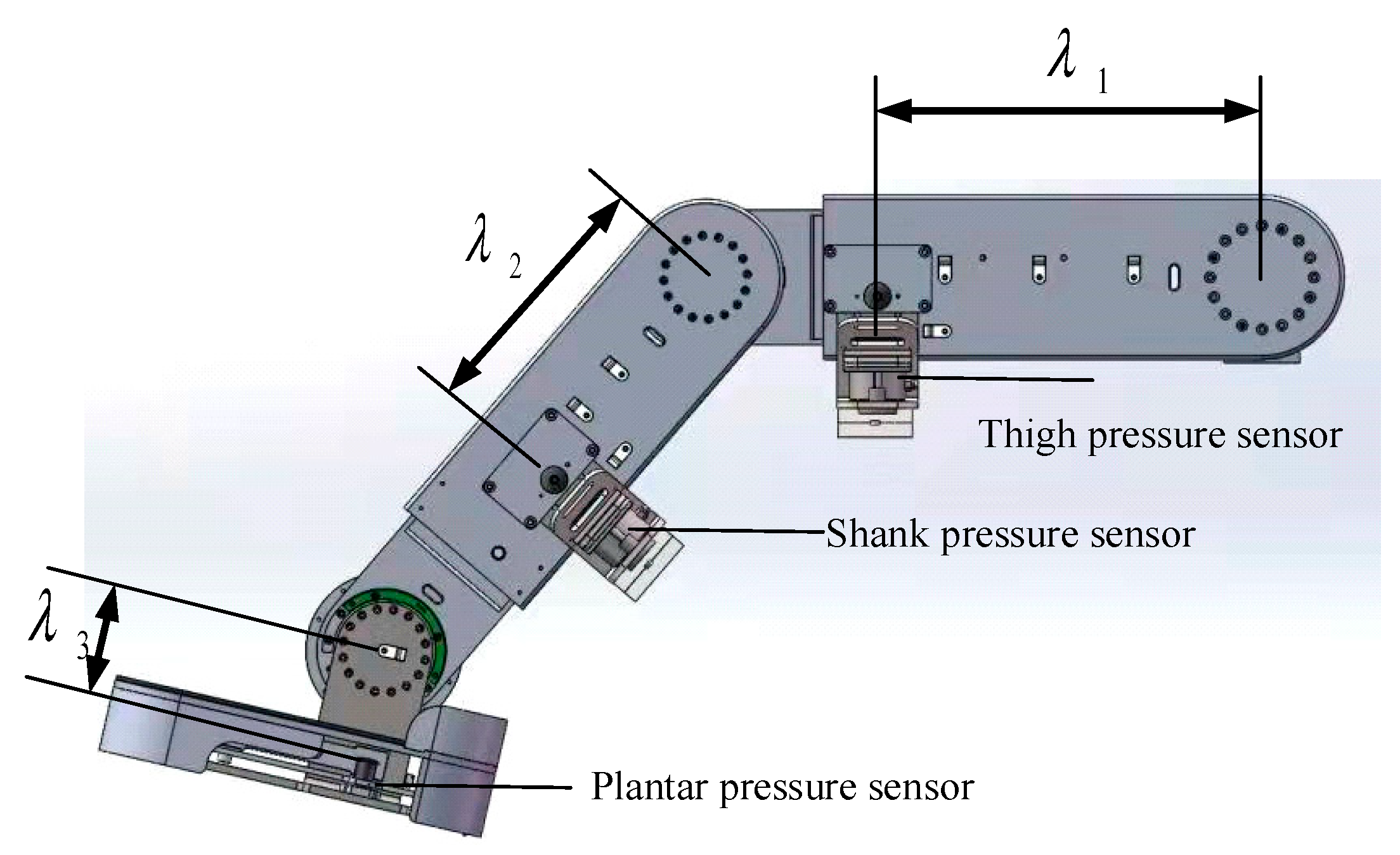
2.1. Mechanical Design and Sensor Systems for of Lebot

The human body inertia parameters can be referred to the National Standard of China (GB/T17245-2004). Table 1 shows the average values of the parameters of each part, and the data refer to the parameters related to adult males aged from 18 to 60 years old and adult females aged from 18 to 55 years old, where H is the body height and M is the body mass.
The mechanical structure of the Lebot is designed according to the principle of modularity. The mechanical structure of the robot consists of three main modules: the movable chassis module, the weight-reducing support seat module, and the exoskeleton mechanical leg module. The overall model of Lebot is shown in Figure 1. The robot can be adjusted to different sizes and support positions according to individual patient differences. During use, the patient is placed in a sitting or lying position with both feet on the pedals of the mechanical leg, the centers of the joints of the lower limbs are aligned with the centers of rotation of the robot joints, and the body is fixed to the robot through safety straps and aids to prevent secondary injuries caused by overturning during the training process [16].
In this study, tension pressure sensors were used to identify HMI forces [17], as shown in Figure 2, with pressure sensors on the thigh, shank, and plantar. The distance between the thigh pressure sensor and center of rotation of hip joint is λ 1 , the distance between the shank pressure sensor and the center of rotation of the knee joint is λ 2 , and the distance between the plantar pressure sensor and the center of rotation of the ankle joint is λ 3 .

2.2. Active Training Based on Fixed Parameters of SDM

In this paper, an active training control strategy based on the SDM is proposed for the middle and late stages of patient rehabilitation [17], and the block diagram of the traditional active training control strategy is shown in Figure 3. The control method includes internal and external closed-loop control. The internal loop uses a sliding mode controller (SMC) to realize the tracking of the actual trajectory of the robotic arm against the set trajectory reflecting the patient’s movement intention. The outer loop uses a SDM to realize the set trajectory to follow the HMI force to achieve the purpose of soft control, in which each motion joint of the rehabilitation robot is regarded as a virtual SDM. The input of the model is the active HMI force, which is identified by the tensile force sensor and sEMG signal; the output of the model is the adjustment amount e of the motion trajectory according to the HMI force, so as to realize the active and soft motor function rehabilitation training and ensure the patient can complete the active training efficiently. The adjustment quantity e is obtained from Equation (1), where x 1 , x 2 , x 3 are the output of the hip, knee, ankle SDM, respectively:
e = x 1 x 2 x 3 T

2.2.1. Virtual Spring-Damping Model

The SDM is shown in Figure 4, where m is the virtual model mass, k is the elasticity coefficient, b is the damping coefficient, x is the displacement, and F is the HMI force.
The SDM can establish the relationship between the HMI force and the joint angle. A dynamic analysis by Newton’s second law of motion shows that:
m x ¨ + b x ˙ + k x = F
The Laplace transform is applied to transform Equation (2) to the frequency domain for analysis as follows:
m s 2 X s + b s X s + k X s = F s
The transfer function of the SDM is obtained by collating:
G s = F s X s = m s 2 + b s + k
The characteristic equation of the spring-damped model system is obtained as follows:
m s 2 + b s + k = 0
Introduction of damping ratio ξ = b 2 k m and intrinsic frequency w n = k m facilitate the analysis of the model. Then, by substituting into the characteristic equation, we can obtain:
s 2 + 2 ξ w n s + w n 2 = 0
The characteristic roots of the characteristic equation are as follows:
s = ξ w n ± w n ξ 2 1
(1)
0 < ξ < 1 . The solution of the characteristic equation is a pair of imaginary conjugate roots. The system is underdamped.
(2)
ξ = 1 . The roots of the characteristic equation are a pair of real weight roots and the damping of the system is in the form of critical damping.
(3)
ξ > 1 . The roots of the characteristic equation are mutually exclusive real roots and the damping of the system is in an overdamped state.
(4)
ξ < 0 . The number of roots of the characteristic equation is greater than 0. The system is unstable.
In addition, the SDM allows not only to derive the relationship between force and position, but also to optimize the stability of the system by adjusting ξ , w n .
The rehabilitation robot controller uses a microprocessor and requires discretization of the kinematic equations of the SDM. The following is an example for a single joint. Assume that the acceleration of the model at moment k is x ¨ i k , the velocity is x ˙ i k , the position is x i k , the interaction force is F i k , and the control period is Δ t . Then, in the spring-damped model, the motion of the mass block at moment k + 1 can be obtained from the equation:
x ¨ i ( k + 1 ) = ( F i k b x ˙ i k k x k ) i / m x ˙ i k + 1 = x ¨ i k Δ t + x ˙ i k x i k + 1 = x i k + x ˙ i k + 1 + x ˙ i k Δ t 2

2.2.2. Research on Trajectory Tracking Disturbance Suppression Method Based on SMC

In practical applications, the linkages of multi-joint lower limb rehabilitation robots have irregular shapes and uneven mass distribution. Considering the influence of the wiring of the electrical control system, the installation of sensors for different purposes, the placement of motors and actuators, etc., and because the components in the robot arm are affected by various factors, including friction, elasticity, inertia, etc., it is difficult for the mathematical model to completely and accurately describe the behavior of the robot arm, and the lower limb rehabilitation robot is a strongly coupled complex nonlinear time-varying system [18]. Disturbances in the external environment can also have an impact on the accuracy of trajectory tracking. For example, muscle spasms or uncoordinated movements of the patient may cause the trajectory of the robotic arm to deviate from the expected trajectory, thus affecting the treatment outcome. To address these challenges, the robotic arms of rehabilitation robots often employ advanced control algorithms to improve accuracy and robustness [19]. In this study, a terminal SMC is used to implement the target trajectory tracking.
The general model of the human–machine coupled system of mechanical legs is:
M q q ¨ + C q , q ˙ q ˙ + G q + τ d = τ + F q , q ˙ , q ¨
where F q , q ˙ , q ¨ = M q q ¨ C q , q ˙ q ˙ G q represents the modeling error of the system, M q denotes the symmetric positive definite inertia matrix of the system, C q , q ˙ denotes the centrifugal and Gauche force matrices of the system, G q denotes the gravity matrix of the system, and τ denotes the control input matrix.
Transforming Equation (9) by extraction yields:
q ¨ = M 1 τ C q , q ˙ q ˙ G q + d t
Among them, d t = M q q ¨ C q , q ˙ q ˙ G q τ d .
For the subsequent application of the control law, Equation (9) can be written in the following form:
z ˙ = h x u + f x , z + d t
Among them, x = q 1 q 2 , z = q 1 ˙ q 2 ˙ T , h x = M 1 , u = τ .
f x , z = M 1 C q , q ˙ q ˙ + G q , d t represents system modeling errors and external perturbations.
The position and velocity signal errors of the system are defined as:
e = q q d e ˙ = q ˙ q ˙ d
where, q d and q ˙ d represent the desired position and velocity signals, respectively. That is, the design objective of this paper is to satisfy:
lim t e = lim t q q d 0
Assume that d(t) is bounded, i.e.:
d K
Design the sliding surface as:
σ = e + J e ˙ p q
where J is a determinant matrix and p/q (p, q are positive odd numbers) to satisfy the condition 1 < p/q < 2.
Derivation of Equation (12) shows that:
σ ˙ = e ˙ + p q J e ˙ p q e ¨
Theorem 1. 
Considering the system (9) with unknown external disturbances are present, using the designed terminal SMC (14), the system trajectory tracking error will converge to a small range near zero.
τ = h x 1 q d ¨ q p J 1 e ˙ 2 p q f x , z k σ K ^ s g n σ
where  k > 0, K ^ represents the estimate of the unknown constant K to compensate for the external perturbations, and  K ~ = K ^ K is set, the designed adaptive law takes the following form:
K ^ = p q J e ˙ p q 1 σ
Proof of Theorem 1. 
The Lyapunov function is set to the following form:
V m = σ T σ + 1 2 K ~ 2
The derivation of Equation (16):
V m ˙ = σ T σ ˙ + K ~ K ^ ˙
Bringing Equation (14) into (17) and collapsing it to obtain:
V m ˙ = σ T e ˙ + p q J e ˙ p q 1 e ¨ + K ^ K K ^ ˙ = p q σ T J e ˙ p q 1 e ¨ + q p J 1 e ˙ 2 p q + K ^ K K ^ ˙ = p q σ T J e ˙ p q 1 q ¨ q d ¨ + q p J 1 e ˙ 2 p q + K ^ K K ^ ˙ = p q σ T J e ˙ p q 1 h · x u + f x , z + d t q d ¨ + q p J 1 e ˙ 2 p q + K ^ K K ^ ˙ = p q σ T J e ˙ p q 1 d + k     σ K ^ s g n σ + K ^ K K ^ ˙ p q σ T J e ˙ p q 1 d k p q σ T J e ˙ p q 1 σ p q σ T J e ˙ p q 1 K ^ + K ^ K K ^ ˙ p q σ T J e ˙ p q 1 K k p q σ T J e ˙ p q 1 σ p q σ T J e ˙ p q 1 K ^ + K ^ K K ^ ˙ = p q σ T J e ˙ p q 1 K ^ ˙ K ^ K k p q σ T J e ˙ p q 1 σ k p q σ T J e ˙ p q 1 σ 0
According to Equation (19), the designed sliding-mode based controller can ensure that the tracking error of the system tends to 0 and the system can be made stable. □

2.3. Active Training by Adding a Fuzzy Adaptive Impedance Parameter Regulator

The spring-damped model control method with fixed parameters described in Section 2.2 of this paper has some active suppleness, although it can adjust the reference motion trajectory according to the active force applied by the human lower limbs. However, the disadvantage of this method is that it is difficult to determine the optimal model parameters to achieve the best active suppleness. This is mainly due to the fact that different patients and the same patient apply different forces to the rehabilitation robot at different times, and the human body impedance characteristics vary, leading to changes in the characteristics of the interaction environment. Therefore, if the impedance parameters are expected to be fixed, it will be difficult to regulate the dynamic relationship between the robot and the patient and will have poor adaptability for training tasks with individual differences. The fixed-parameter SDM control method is less robust and cannot adapt to changes in external environmental parameters, and its active flexibility still needs further improvement.
In order to achieve an active and adaptive rehabilitation training environment, this paper proposes a fuzzy adaptive impedance parameter active control scheme based on the SDM as shown in Figure 5. For the dynamic change of impedance parameters during rehabilitation training, the SDM of the outer ring incorporates a fuzzy adaptive impedance parameter regulator to adjust the damping coefficient and the stiffness coefficient in real time with the HMI force, the state fluctuation rate (SFR) of the affected limb [20], the position deviation and the velocity deviation as inputs, so as to achieve the human impedance. The damping and stiffness coefficients are adjusted in real time as inputs to achieve the self-adaptation of human impedance.
SFR, calculated using Equation (20):
S F R = τ h ˙
where τ h is the interaction force between the affected limb and a single joint of the robot. The smaller the fluctuation of the actual interaction force between the affected limb and the end of the robot, the more stable the state of the affected limb and the smaller the SFR, which is normalized to be in the range of (0, 1).
The HMI force actively exerted by the patient is an intuitive representation of the patient’s motor intention. In the process of active rehabilitation training, the motor impedance can be adjusted according to the interaction force actively applied by the patient, and a motor impedance adaptive regulator based on the patient’s active motor intention can be constructed: when the affected limb deviates from the reference trajectory, the motor impedance will increase accordingly, and the patient will feel the strain; on the contrary, the motor impedance will decrease accordingly. When the SFR value calculated by the patient’s motion state assessment module is smaller, it means that the HMI force is more stable and the patient’s motion state is better, and the motion impedance will increase appropriately; on the contrary, the motion impedance will decrease. Therefore, in this section, the range of the deviation of the affected limb from the set trajectory, the interaction force reflecting the patient’s movement intention, and the SFR value calculated by the patient’s movement state assessment module are used as the basis to design the adaptive regulator of impedance parameters to dynamically adjust the movement impedance in real time, so as to build an active and soft rehabilitation training environment for the patient and avoid the secondary injury of the affected limb while stimulating the patient’s enthusiasm to participate in training.
The fuzzy adaptive impedance parameter regulator introduced in this paper consists of two parts: a fuzzy variable stiffness adaptive regulator and a fuzzy variable damping adaptive regulator. The fuzzy variable stiffness adaptive regulator adjusts the optimal stiffness coefficient matrix dynamically in real time to achieve the adaptive adjustment of the stiffness according to the amount of angular change of the motion trajectory and the interaction force exerted by the human lower limbs on the lower limb mechanism of the rehabilitation robot. The fuzzy variable damping adaptive regulator, on the other hand, dynamically adjusts the optimal damping coefficient matrix in real time according to the amount of angular velocity variation of the motion trajectory and the interaction force exerted by the human lower limb on the lower limb mechanism of the rehabilitation robot in order to achieve the adaptive adjustment of damping. In addition, this paper also uses SFR as the coefficient of the variation amount of stiffness coefficient and the variation amount of damping coefficient.
(1)
Design of fuzzy variable stiffness adaptive regulator
In the design of the fuzzy variable stiffness adaptive regulator, the angular deviation from the reference trajectory q and the active interaction force τ exerted by the patient’s limb on the robot’s lower limb mechanism are used as inputs to the regulator and are divided into 5 levels for fuzzy adjustment, namely positive large, positive small, zero, negative small, and negative large, which are represented by LP, P, Z, N, and LN, respectively. The adjustment quantity K of the stiffness coefficient matrix is used as the output of the regulator, which is also divided into 5 levels. The fuzzy rules of variable stiffness coefficients designed according to the magnitude of the patient’s deviation from the range of motion of the reference trajectory and the active interaction force exerted by the patient’s affected limb on the robot’s lower limb mechanism are shown in Table 1. The fuzzy inference method is applied to obtain the adjustment of the stiffness coefficient K . The optimal stiffness coefficient is then K * ,
K * = K + 1 S F R K
(2)
Design of fuzzy variable damping adaptive regulator
Similarly, the inputs to the fuzzy variable damping coefficient regulator, i.e., the change in the angular velocity of the motion trajectory q ˙ and the active interaction force τ applied by the patient to the robot, are also fuzzy-adjusted in 5 levels. The adjustment quantity ∆B of the damping coefficient matrix is used as the output of the regulator, which is also divided into 5 levels. The fuzzy rules of the variable damping coefficient based on the error of the joint angular velocity and the active interaction force exerted by the patient on the robot are shown in Table 2. The optimal damping coefficient is B * , which is obtained by applying the fuzzy inference method (Table 3).
B * = B + 1 S F R B

3. Results

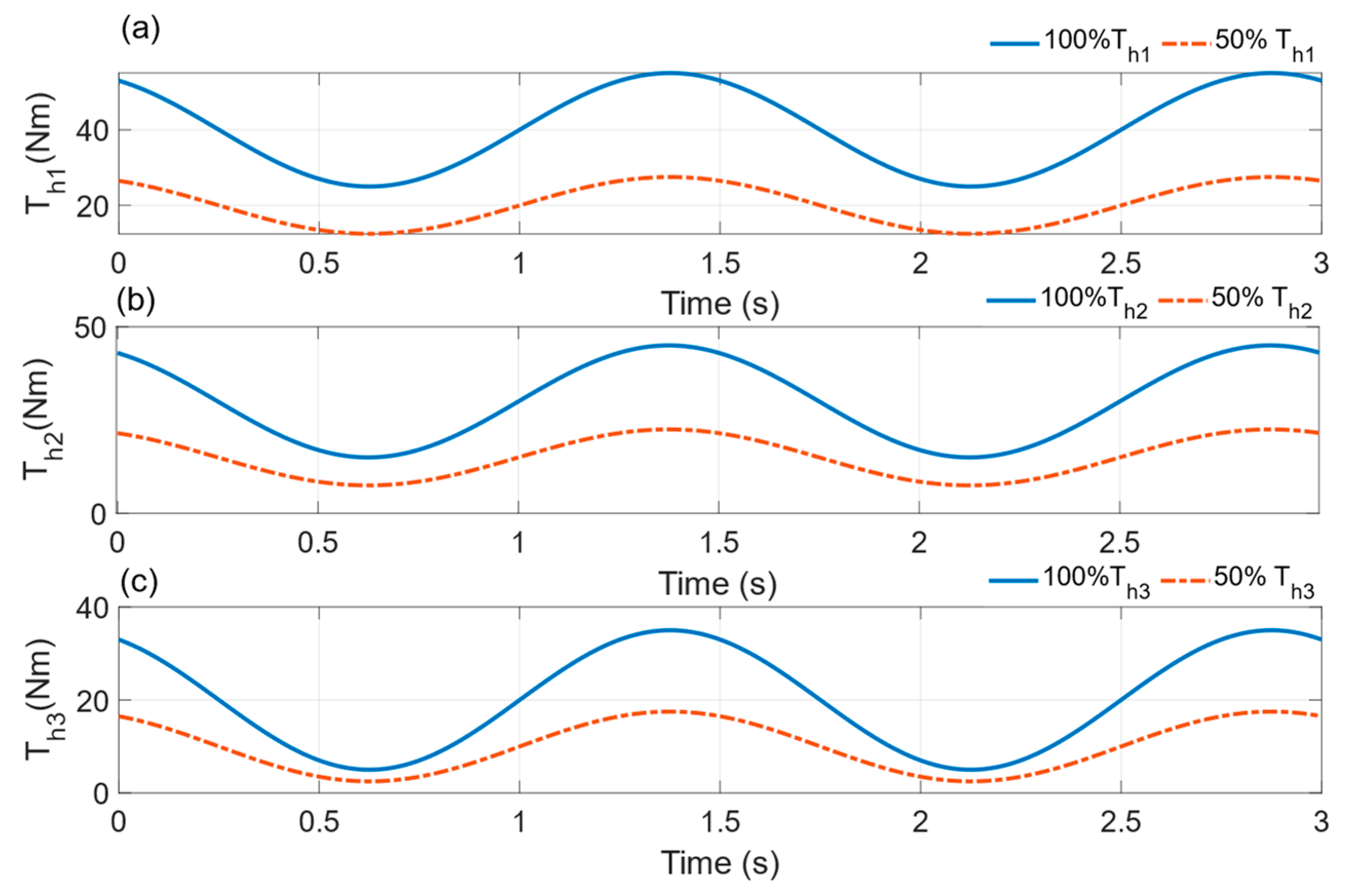
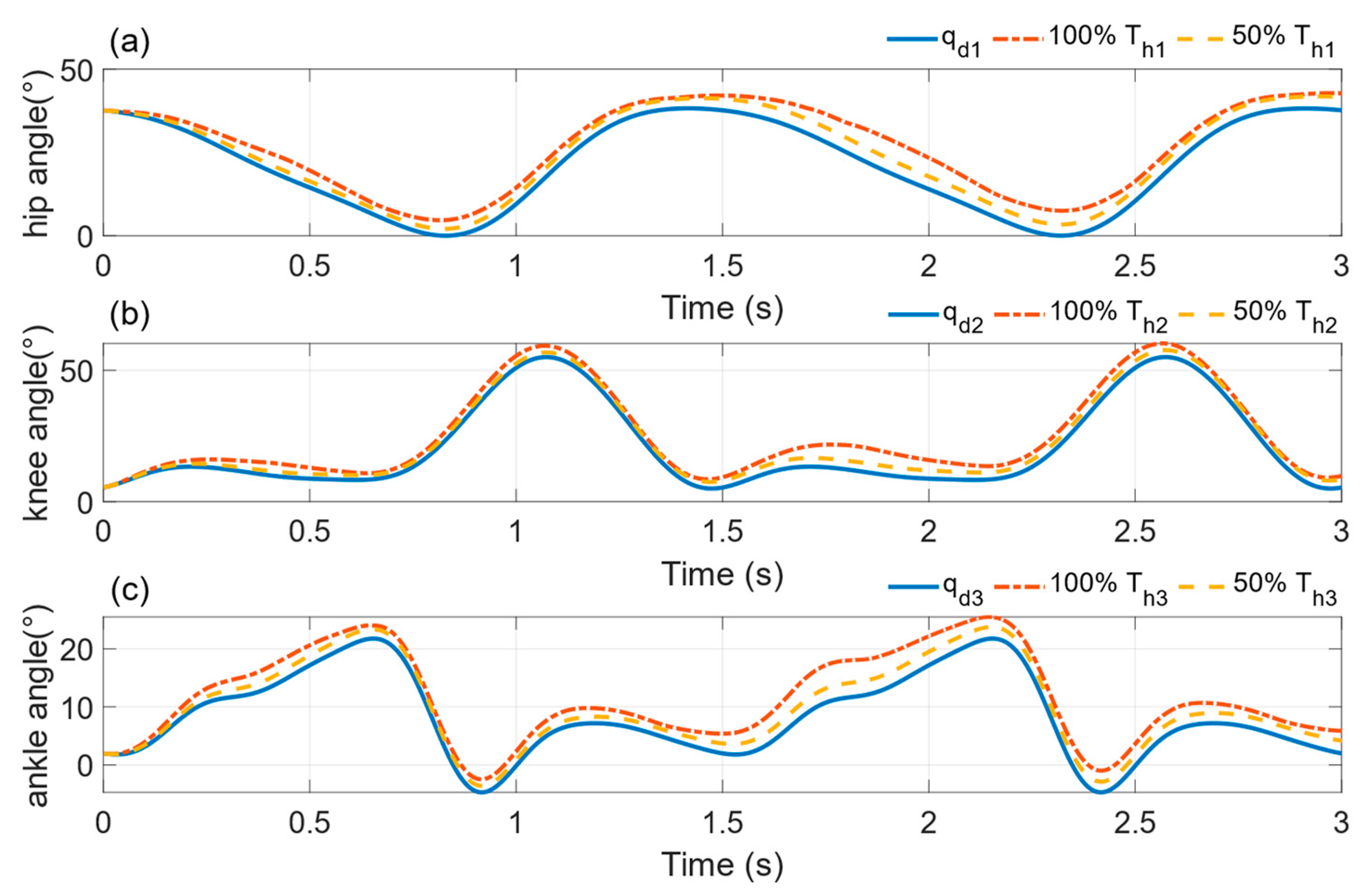
3.1. Simulation Verification Experiments

In this section, the proposed fuzzy adaptive impedance parameter regulator is verified by simulation experiments. The hip, knee, and ankle joint models of the right leg of the Lebot system are imported into MATLAB and Simulink. The control objective is to make the angular outputs q 1 , q 2 , and q 3 of the right hip, knee, and ankle joints of the human–robot system follow the desired trajectories q d 1 , q d 2 , and q d 3 . The desired trajectory is a gait planning curve, and the initial parameters of the SDM are set as follows: m = 1, b = 5, k = 2, and the simulation time is set as 3 s. The desired trajectory of each joint is shown in Figure 6.
In order to simulate the change of patients’ interaction force, this paper artificially designed the patients’ interaction force in the simulation, as shown in Figure 7. In order to simulate two patients with different motor abilitis, two groups of interaction force were designed, which are 100% interaction force ( 100 % τ h i ) and 50% interaction force ( 50 % τ h i ); 100 % τ h i indicates the patient with strong motor ability, as shown by the blue dashed line in Figure 7, and 50 % τ h i indicates the patient with weak motor ability, as shown in Figure 7 by the red solid line.
The design in this paper includes a fixed parameter impedance controller and an adaptive variable impedance controller based on fuzzy rules, and they are simulated, and the results are shown in Figure 8 and Figure 9. In Figure 8, the impedance parameter is a fixed value, the red solid line indicates the reference trajectory, and the yellow dotted dashed line and the blue dashed line indicate the actual trajectory of the joint under 100 % τ h i and 50 % τ h i , respectively. These trajectories show the adjustment of the joint trajectory by the fixed parameter impedance controller under different magnitudes of interaction forces. With the results in Figure 8, we can see that the actual trajectory of the joint deviates from the reference trajectory, which indicates that when the simulated subject generates interaction forces with the exoskeletal leg, the impedance controller outputs the trajectory deviation to adapt the movement to the moment applied by the subject to the joint in order to prevent excessive confrontation between the exoskeletal leg and the patient’s lower limb and to avoid damage to the patient by moving according to the fixed trajectory in unexpected situations. The flexibility and safety of the patient are ensured.
However, it can be seen from Figure 8 that when the deviation of the output of the impedance controller with fixed impedance parameters is larger, the patient interaction force is larger, which indicates that the patient is recovering better in this rehabilitation stage or is less fatigued in this training, and the active training difficulty needs to be increased to avoid inertia of the patient, which affects the training effect. Therefore, this paper proposes an adaptive variable impedance controller based on fuzzy rules, which can adjust the training intensity according to the changes of the patient’s current state. As shown in Figure 9b, this adaptive variable impedance controller can change the stiffness coefficient and damping coefficient to reduce the maximum deviation of the knee joint angle to 10.54° and 5.61°, respectively. This indicates that the action of the adaptive variable impedance controller can increase the training intensity and thus contribute to a better recovery of the patient.

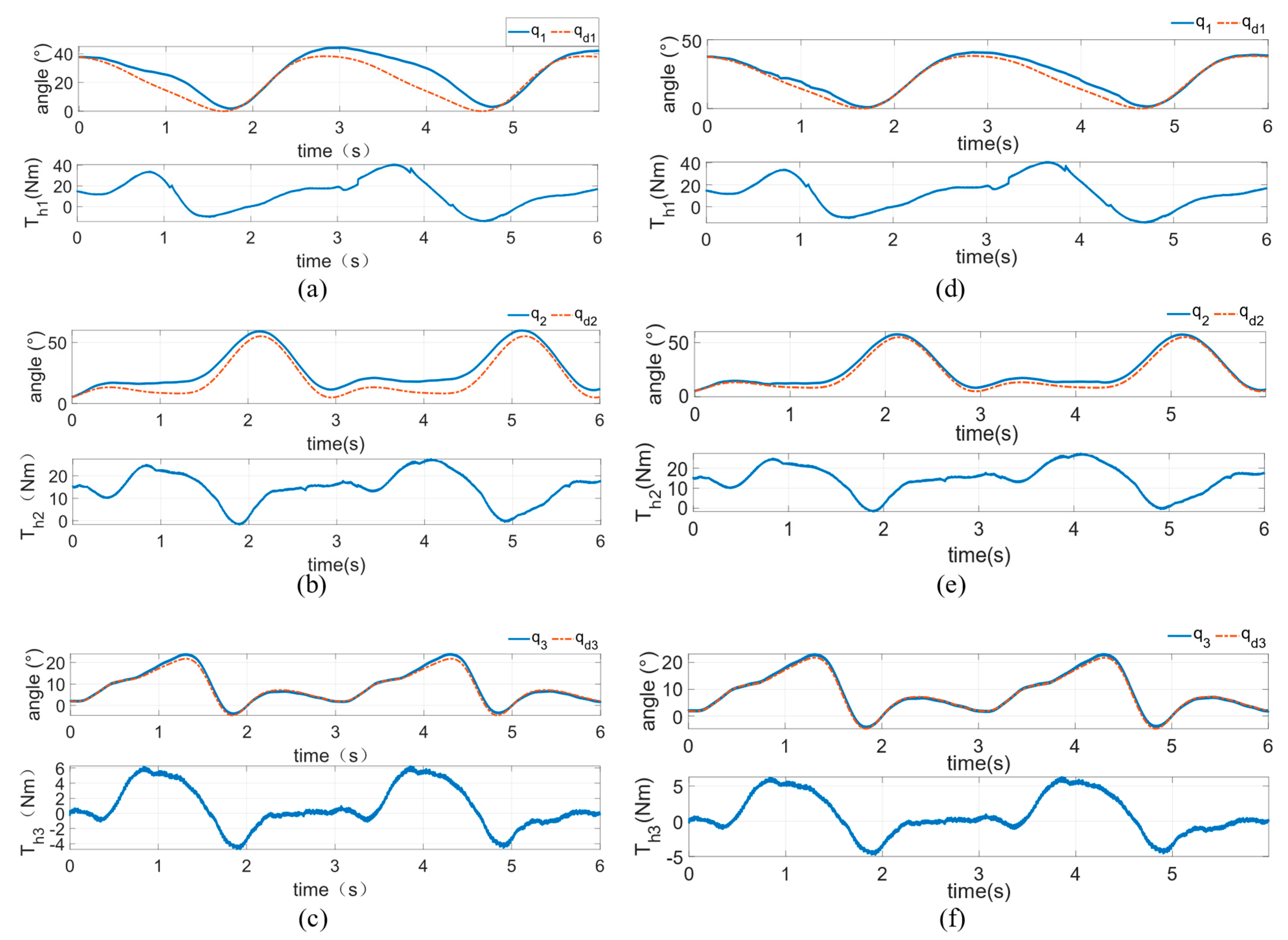
3.2. Actual Verification Experiments

To evaluate the effectiveness of the active training strategy proposed in the paper during rehabilitation training, we conducted a test experiment with normal subjects. The Lebot system was selected as the experimental platform. The subject was a 32 years old male, 178 cm in height and 69 kg weight, recorded as S1. The equipment posture was adjusted to supine position before training. During the experiment, hip, knee, and ankle joint angle data and subject interaction force data were collected. The experiments were divided into two groups, one experiment fixed the impedance parameters of the SDM, and the other experiment used the active training control strategy of fuzzy adaptive impedance proposed in this paper. Subject S1 was required to deliver approximately the same force for each gait cycle as possible during the experiment. After completing the training, to avoid the disturbance of anomalies, the data from each gait cycle were averaged to analyze the relationship between the actual joint angles during active training and the target trajectory and subject interaction forces to compare the differences between the two groups of active training. The object of this experiment is the hip, knee, and ankle joints of the right leg of the subject. The control objective is that the actual angles q 1 , q 2 , q 3 of the right leg hip, knee, and ankle joints of the man–machine system follow the desired trajectories q d 1 , q d 2 , q d 3 .
The active training results of the subjects under the action of the spring-damped model controller with fixed impedance parameters are shown in Figure 10a–c. The actual trajectories q 1 , q 2 , q 3 will softly deviate from the desired trajectories q d 1 , q d 2 , q d 3 under the action of the actual HMI torques τ h 1 , τ h 2 , τ h 3 . It can be seen from Figure 10 that there is a certain shake in the HMI force, but the output actual trajectories do not produce corresponding shake, indicating that the spring-damped model output trajectory offset has a certain anti-disturbance ability, and the model has well stability. It is worth mentioning that the maximum offset angles of the hip, knee, and ankle joints are 16.3°, 10.6°, and 2.5°, respectively. Under the action of the fuzzy adaptive impedance controller, the active training results of the subjects are shown in Figure 10d–f, in which the actual trajectories q 1 , q 2 , q 3 deviate softly from the desired trajectories q d 1 , q d 2 , q d 3 under the action of the actual HMI torques τ h 1 , τ h 2 , τ h 3 . The maximum offset angles of the hip, knee, and ankle joints are 7.74°, 5.9°, and 1.5°, respectively. The significant decrease compared with the active training with fixed impedance parameters indicates that the parameters of the SDM changed during the training process, automatically increasing the elasticity and damping coefficients of the model and increasing the difficult factor of the active training when the subject increased the interaction force, and automatically decreasing the elasticity and damping coefficients of the model and decreasing the difficult factor of the active training when the subject decreased the interaction force.

4. Discussion

Through experiments, it is shown that an adaptive variable impedance control method based on fuzzy rules is proposed in this paper, which provides an active, flexible, and efficient rehabilitation training environment for patients. The control scheme consists of an inner loop and an outer loop; for the problem of dynamic changes of optimal impedance parameters during rehabilitation training, the outer loop adopts an adaptive control method based on the fuzzy adjustment of impedance parameters, taking the HMI force, position, and speed deviation as the input of the adaptive regulator of impedance parameters, and using fuzzy reasoning to adjust the damping coefficient and stiffness coefficient in real time to adjust the active training for the current motion state of the human body. The intensity of the human lower limb and the exoskeleton leg can be avoided to avoid excessive confrontation and ensure the safety of patients in training. Through the experimental study, it was found that the SDM proposed in this study has well stability and can realize the actual trajectory to follow the patient’s active interaction moment with certain flexibility; more importantly, the fuzzy adaptive impedance controller proposed in this study performs well in regulating the active training difficulty factor, can fully stimulate the patient’s active training participation, can reduce the training difficulty factor when the patient’s interaction force decreases, can increase the patient’s confidence in active training, and increase the training difficulty factor when the patient’s active ability is enhanced. Thus, the system can achieve the purpose of the adaptive adjustment of impedance according to the patient’s motor ability during the patient’s active training. The system performs well in stimulating the patient’s active movement, which proves that the active training control method of the rehabilitation robot based on fuzzy adaptive impedance adjustment is reasonable and effective.

5. Conclusions

In this paper, an adaptive impedance active training control method is proposed. Firstly, the SDM is used to achieve the joint angle following of to the patient’s interaction force, so as to achieve the purpose of soft interaction; then, the sliding mode control is used to achieve the tracking of the desired trajectory and improve the robustness. Finally, the idea of fuzzy control is used to change the impedance parameters of the SDM according to the change of the patient’s interaction force, so as to change the difficulty of active training and fully mobilize the patient’s active participation. Further research can include virtual reality game scenarios to improve patient motivation.

Author Contributions

Conceptualization, J.H.; data curation, J.H.; methodology, J.H.; software, J.H. and Y.Z.; supervision, Q.M. and H.Y.; writing—original draft, J.H.; writing—review and editing, J.H. All authors have read and agreed to the published version of the manuscript.

Funding

This work was supported in part by the National Natural Science Foundation of China under Grant 62073224.

Data Availability Statement

The data are made available through the corresponding authors’ emails.

Acknowledgments

The authors would like to thank the National Natural Science Foundation of China under Grant 62073224.

Conflicts of Interest

The authors declare no conflict of interest exist in the submission of this manuscript, and the manuscript has been approved by all authors for publication.

References

  1. Soltani Sharif Abadi, A.; Alinaghi Hosseinabadi, P.; Hameed, A.; Ordys, A.; Pierscionek, B. Fixed-Time Observer-Based Controller for the Human–Robot Collaboration with Interaction Force Estimation. Int. J. Robust Nonlinear Control. 2023. [Google Scholar] [CrossRef]
  2. Liu, A.; Chen, T.; Zhu, H.; Fu, M.; Xu, J. Fuzzy Variable Impedance-Based Adaptive Neural Network Control in Physical Human–Robot Interaction. Proc. Inst. Mech. Eng. Part I J. Syst. Control. Eng. 2023, 237, 220–230. [Google Scholar] [CrossRef]
  3. Miao, Q.; Zhang, M.; Cao, J.; Xie, S. Reviewing High-Level Control Techniques on Robot-Assisted Upper-Limb Rehabilitation. Adv. Robot. 2018, 32, 1253–1268. [Google Scholar] [CrossRef]
  4. Shi, D.; Zhang, W.; Zhang, W.; Ding, X. A Review on Lower Limb Rehabilitation Exoskeleton Robots. Chin. J. Mech. Eng. 2019, 32, 74. [Google Scholar] [CrossRef]
  5. Shi, D.; Zhang, W.; Zhang, W.; Ju, L.; Ding, X. Human-Centred Adaptive Control of Lower Limb Rehabilitation Robot Based on Human–Robot Interaction Dynamic Model. Mech. Mach. Theory 2021, 162, 104340. [Google Scholar] [CrossRef]
  6. Farhadiyadkuri, F.; Popal, A.M.; Paiwand, S.S.; Zhang, X. Interaction Dynamics Modeling and Adaptive Impedance Control of Robotic Exoskeleton for Adolescent Idiopathic Scoliosis. Comput. Biol. Med. 2022, 145, 105495. [Google Scholar] [CrossRef] [PubMed]
  7. Feng, H.; Song, Q.; Yin, C.; Cao, D. Adaptive Impedance Control Method for Dynamic Contact Force Tracking of Robotic Excavators. J. Constr. Eng. Manag. 2022, 148, 04022124. [Google Scholar] [CrossRef]
  8. Omrani, J.; Moghaddam, M.M. Nonlinear Time Delay Estimation Based Model Reference Adaptive Impedance Control for an Upper-Limb Human-Robot Interaction. Proc. Inst. Mech. Eng. Part H J. Eng. Med. 2022, 236, 385–398. [Google Scholar] [CrossRef] [PubMed]
  9. Mohebbi, A. Human-Robot Interaction in Rehabilitation and Assistance: A Review. Curr. Robot. Rep. 2020, 1, 131–144. [Google Scholar] [CrossRef]
  10. Harandi, M.R.J. Comments on “Novel Adaptive Impedance Control for Exoskeleton Robot for Rehabilitation Using a Nonlinear Time-Delay Disturbance Observer”. ISA Trans. 2022, 136, 755–757. [Google Scholar] [CrossRef] [PubMed]
  11. Huang, Z.; Liu, J.; Li, Z.; Su, C.-Y. Adaptive Impedance Control of Robotic Exoskeletons Using Reinforcement Learning. In Proceedings of the 2016 International Conference on Advanced Robotics and Mechatronics (ICARM), Macau, China, 18–20 August 2016; pp. 243–248. [Google Scholar]
  12. Huo, W.; Mohammed, S.; Amirat, Y.; Kong, K. Active Impedance Control of a Lower Limb Exoskeleton to Assist Sit-to-Stand Movement. In Proceedings of the 2016 IEEE international conference on robotics and automation (ICRA), Stockholm, Sweden, 16–21 May 2016; pp. 3530–3536. [Google Scholar]
  13. Jamwal, P.K.; Hussain, S.; Ghayesh, M.H.; Rogozina, S.V. Impedance Control of an Intrinsically Compliant Parallel Ankle Rehabilitation Robot. IEEE Trans. Ind. Electron. 2016, 63, 3638–3647. [Google Scholar] [CrossRef]
  14. Koopman, B.; van Asseldonk, E.H.; van der Kooij, H. Selective Control of Gait Subtasks in Robotic Gait Training: Foot Clearance Support in Stroke Survivors with a Powered Exoskeleton. J. Neuroeng. Rehabil. 2013, 10, 3. [Google Scholar] [CrossRef] [PubMed]
  15. YFeng, Y.; Wang, H.; Yan, H.; Wang, X.; Jin, Z.; Vladareanu, L. Research on Safety and Compliance of a New Lower Limb Rehabilitation Robot. J. Healthc. Eng. 2017, 2017, 1523068. [Google Scholar]
  16. Hu, J.; Zhuang, Y.; Zhu, Y.; Meng, Q.; Yu, H. Intelligent Parametric Adaptive Hybrid Active–Passive Training Control Method for Rehabilitation Robot. Machines 2022, 10, 545. [Google Scholar] [CrossRef]
  17. Hu, J.; Meng, Q.; Zhu, Y.; Zhang, X.; Wu, W.; Yu, H. Spring Damping Based Control for a Novel Lower Limb Rehabilitation Robot with Active Flexible Training Planning. Technol. Healthc. Care 2022, 31, 565–578. [Google Scholar] [CrossRef] [PubMed]
  18. Meng, W.; Liu, Q.; Zhou, Z.; Ai, Q.; Sheng, B.; Xie, S. Recent Development of Mechanisms and Control Strategies for Robot-Assisted Lower Limb Rehabilitation. Mechatronics 2015, 31, 132–145. [Google Scholar] [CrossRef]
  19. Yang, J.; Su, H.; Li, Z.; Ao, D.; Song, R. Adaptive Control with a Fuzzy Tuner for Cable-Based Rehabilitation Robot. Int. J. Control. Autom. Syst. 2016, 14, 865–875. [Google Scholar] [CrossRef]
  20. Pehlivan, A.U.; Losey, D.P.; O’Malley, M.K. Minimal Assist-as-Needed Controller for Upper Limb Robotic Rehabilitation. IEEE Trans. Robot. 2015, 32, 113–124. [Google Scholar] [CrossRef]
Figure 1. The general structure of the Lebot.
Machines 11 00565 g001
Figure 2. Description of pressure sensor locations.
Machines 11 00565 g002
Figure 3. Block diagram of active training control based on fixed parameters of spring-damping model.
Machines 11 00565 g003
Figure 4. Spring-damping model.
Machines 11 00565 g004
Figure 5. Block diagram of HMI control based on fuzzy adaptive impedance parameter regulator.
Machines 11 00565 g005
Figure 6. Expected trajectory of hip, knee, and ankle joints.
Machines 11 00565 g006
Figure 7. Subjects’ interaction force simulation curve (a) Hip joint interaction torque simulation, (b) Knee joint interaction torque simulation, (c) Ankle joint interaction torque simulation.
Machines 11 00565 g007
Figure 8. Trajectory curve under the action of fixed parameter impedance controller (a) Hip joint trajectory curve, (b) Knee joint trajectory curve, (c) Ankle joint trajectory curve.
Machines 11 00565 g008
Figure 9. Trajectory curve under the action of adaptive variable impedance controller based on fuzzy rules (a) Hip joint trajectory curve, (b) Knee joint trajectory curve, (c) Ankle joint trajectory curve.
Machines 11 00565 g009
Figure 10. Subjects’ joint trajectory−interaction torque curves Fixed−parameter impedance controller results: (a) hip; (b) knee; (c) ankle. Fuzzy adaptive impedance regulator results: (d) hip; (e) knee; (f) ankle.
Machines 11 00565 g010
Table 1. Inertial parameters of human lower limb segments.
Lower Limb SegmentsLengthCenter of Mass PositionMass
Upper trunkL0 = 0.470HR0 = 0.264HM0 = 0.607M
ThighsL1 = 0.245HR1 = 0.106HM1 = 0.107M
CalfL2 = 0.246HR2 = 0.107HM2 = 0.046M
FootL3 = 0.074HR3 = 0.018HM3 = 0.016M
Table 2. Table of fuzzy rules for variable stiffness coefficient K.
q τ
NBNSZOPSPB
NBNBNSNSZOZO
NSNSNSZOZOPS
ZONSZOZOZOPS
PSZOZOZOPSPB
PBZOZOZOPBPB
Table 3. Table of fuzzy rules for variable damping factor B.
B τ
NBNSZOPSPB
NBNBNSNSZOZO
NSNSNSZOZOPS
ZONSZOZOZOPS
PSZOZOZOPSPB
PBZOZOZOPBPB
Disclaimer/Publisher’s Note: The statements, opinions and data contained in all publications are solely those of the individual author(s) and contributor(s) and not of MDPI and/or the editor(s). MDPI and/or the editor(s) disclaim responsibility for any injury to people or property resulting from any ideas, methods, instructions or products referred to in the content.

