
Horizontal Tensile Machine for Mechanical Tests Applicable to Suspension Clamps, Transmission Line Accessories, and Overhead Conductors

 and
and
Abstract
1. Introduction
2. Materials and Methods
2.1. Fundamentals
Slenderness Limits
2.2. Machine analysis
- (a)
- Traction system: spindle, packed guides, pulleys, and servo-reducer;
- (b)
- Clamping system: forks and plates;
- (c)
- Test stroke length;
- (d)
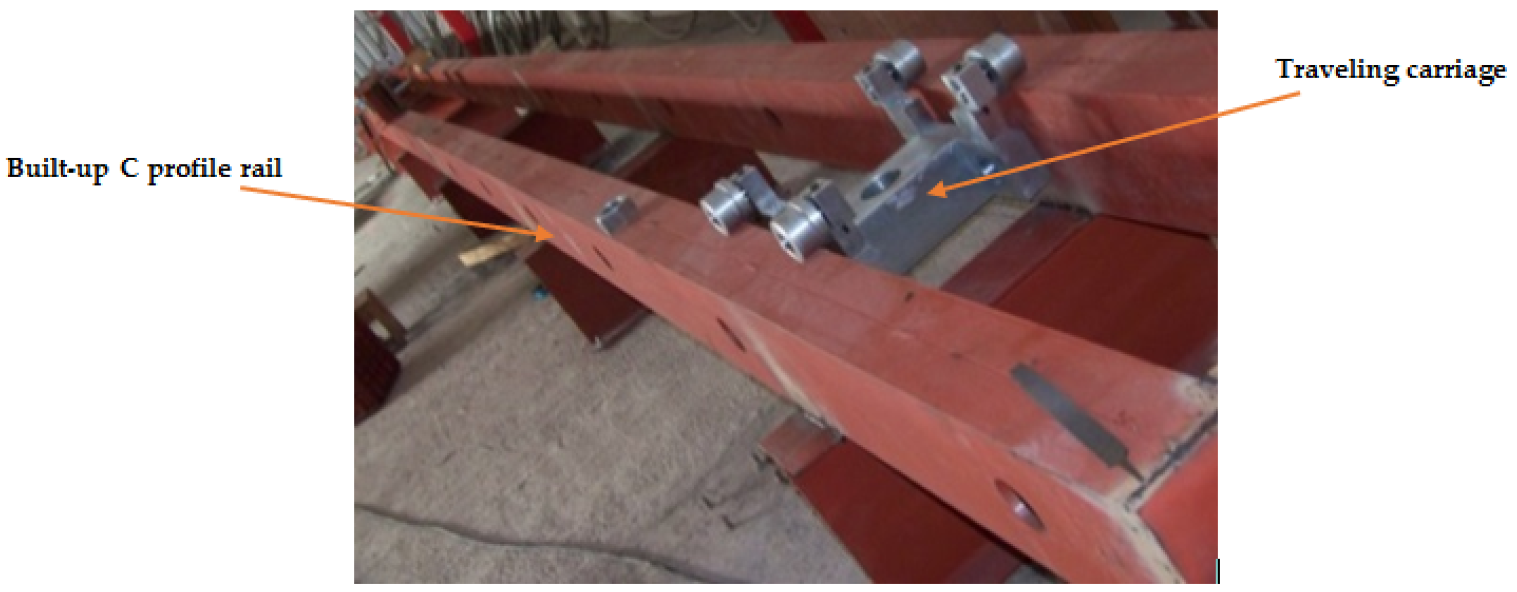
- Tailstock or movable carriage;
- (e)
- Welded mechanical structure;
- (f)
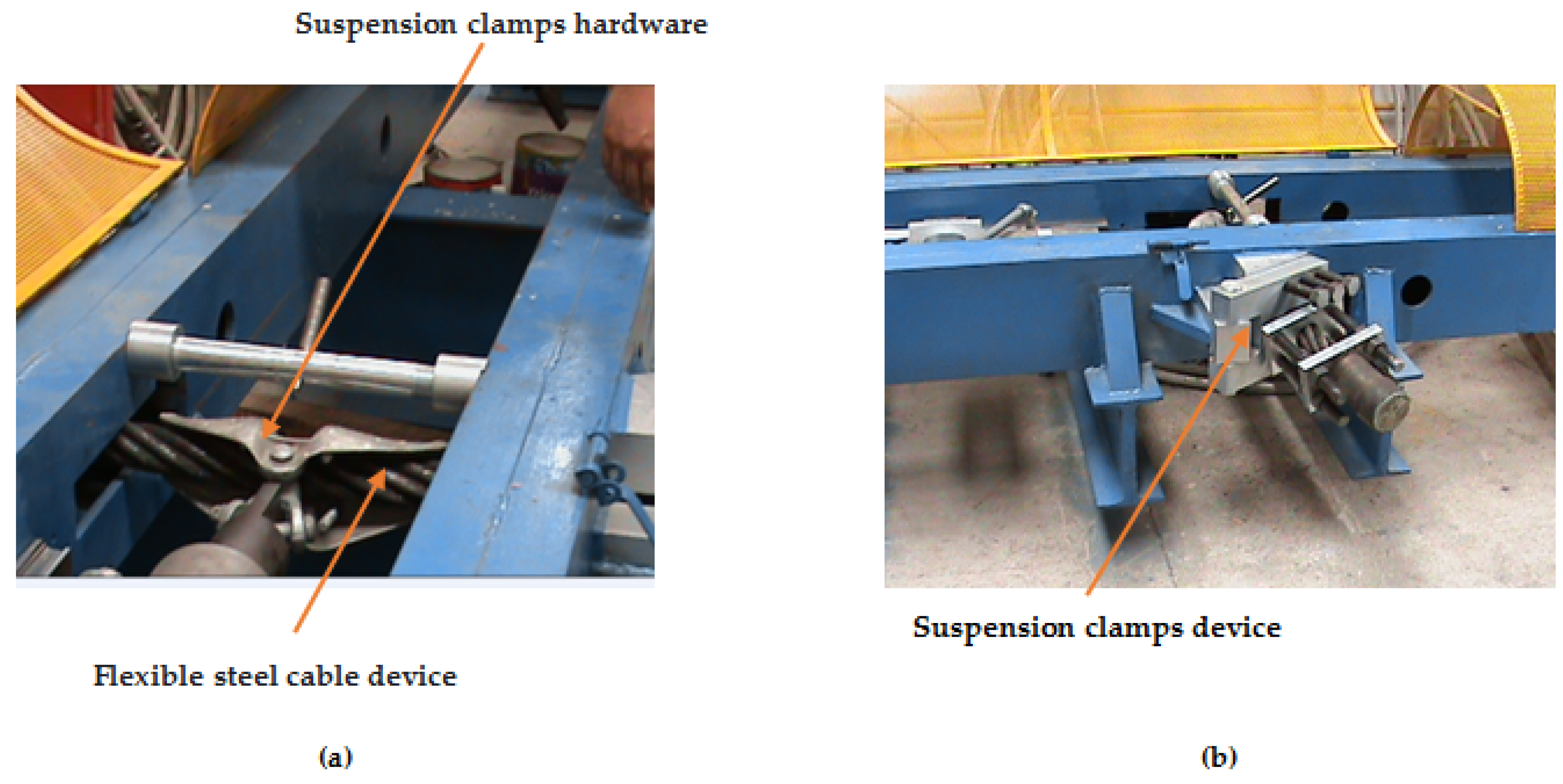
- Suspension clamp device.
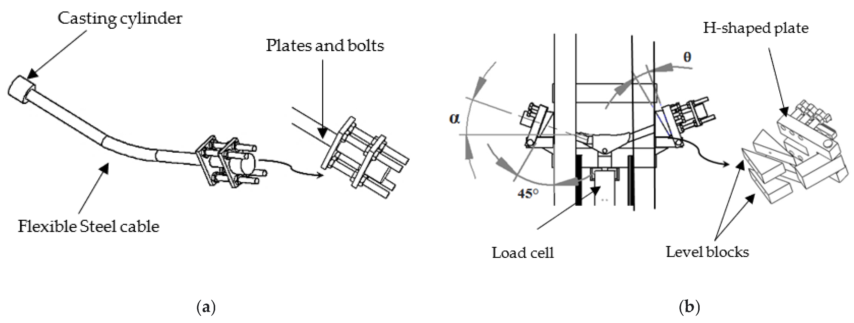
2.2.1. Suspension Clamp Device
2.2.2. Movable Carriage
2.2.3. Structure
- Tensile load capacity up to 300 kN;
- Having suspension clamps integrated into the structure, which requires minimal set-up;
- Ability to include tests in which the clamping for the specimens can use a fork-plate.
3. Results
3.1. Analytical Method
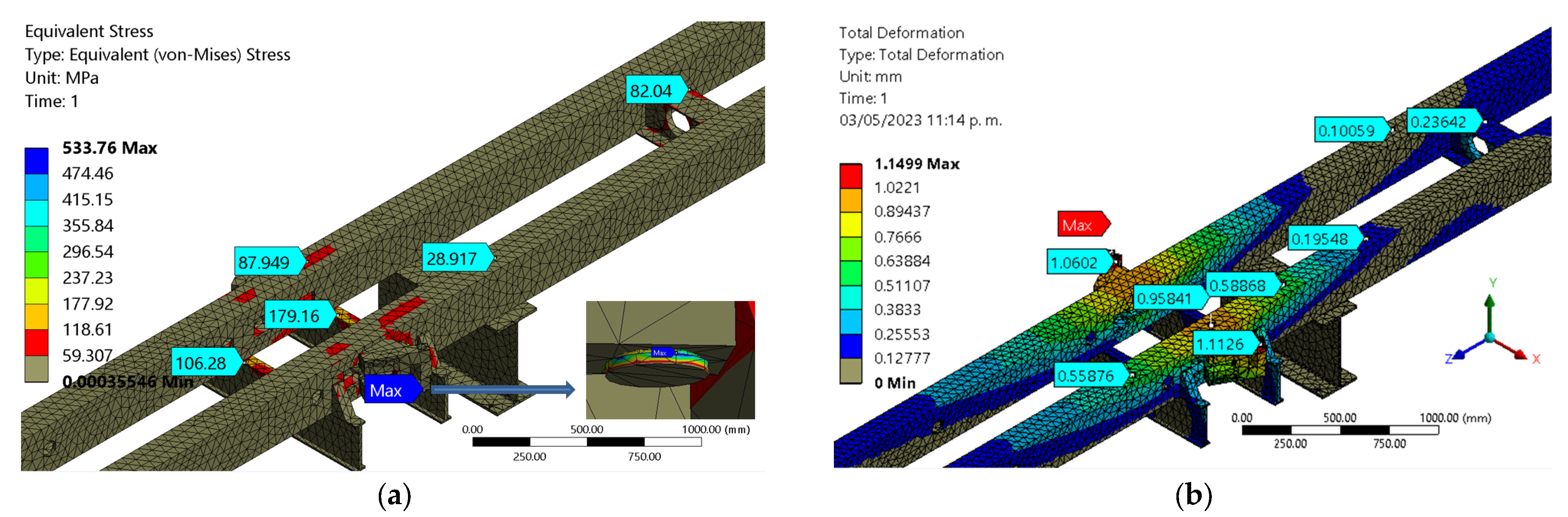
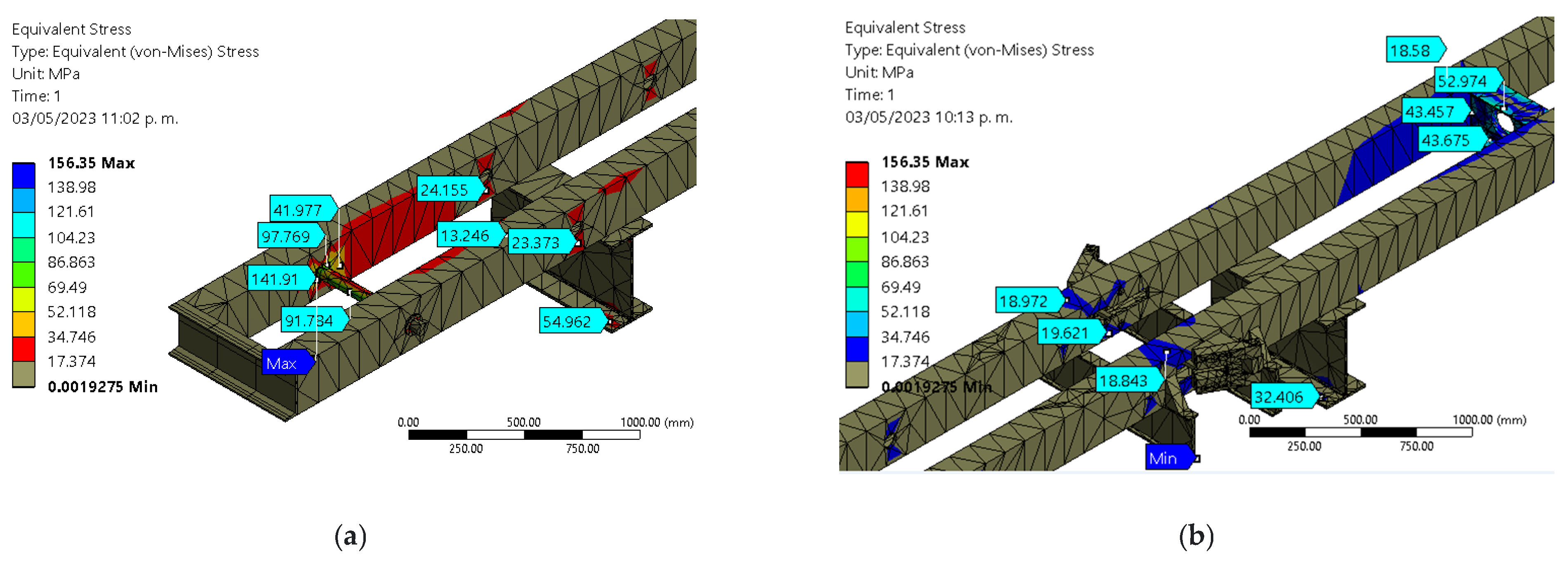
3.2. Numerical Method
3.2.1. Suspension Clamps Device Test
3.2.2. Overhead Conductors
3.3. Manufacture
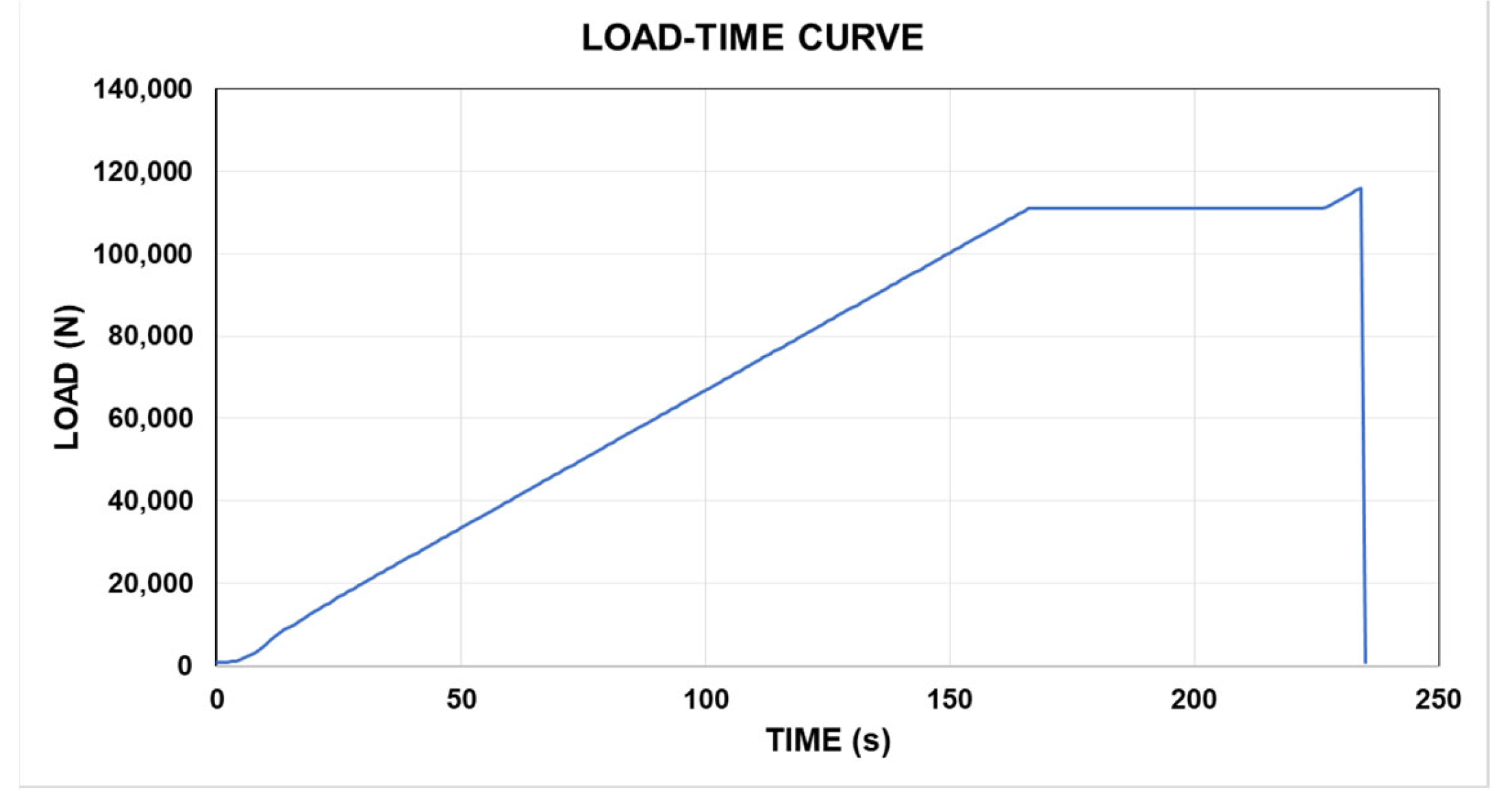
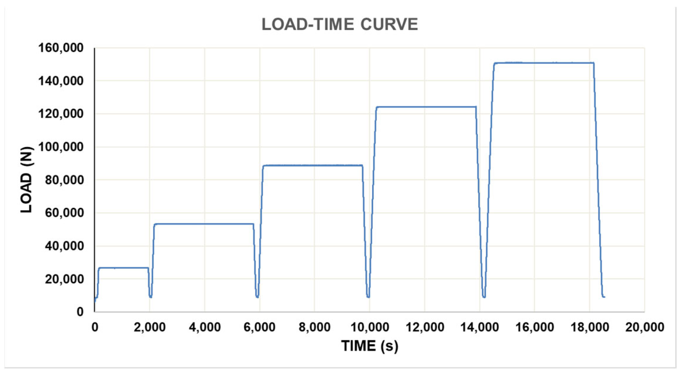
3.4. Laboratory Test
4. Discussion
5. Patents
Author Contributions
Funding
Conflicts of Interest
Nomenclature
| = Holes cross sectional area | r = Radius of gyration |
| α = Suspension clamp dangle angle | K = Effective length factor |
| LRFD = Load and resistance factor design | b= Flange dimension |
| = Net cross-sectional area of member | E = Modulus of elasticity |
| = Gross cross-sectional area of member | h= Web dimension |
| = Width-to- Thickness Ratio | = Elastic buckling stress |
| = Nominal compressive strength | tf = Flange thickness |
| = Limiting Width-to-Thickness Ratio | tw = Web thickness |
| = Transverse center-to-center spacing (gage) between fastener gage lines | = Yield strength |
| = KL = Effective length of member | = Critical stress |
| L = Laterally unbraced length of the member | = Longitudinal center-to-center spacing (pitch) of any two consecutive holes |
| = Load and Resistance Factor Design (LRFD) |
References
- International Standard IEC 61284-1997; Overhead Lines-Requirements and Test for Fittings, International Electro Technical Commission. British Standards Institution: London, UK, 1997.
- Xiong, Y.; Hu, Q.; Song, R. Zhejiang University of Technology, Slow Strain Rate Tension Test Clamp. China Patent CN106153452, 23 November 2016. [Google Scholar]
- You, W.; Lyu, X.; Kong, D.; Wang, L.; Yao, W.; Zhu, X.; Zhu, D. Jiangdong FIttings Equipment. China Patent CN205192743, 27 April 2016. [Google Scholar]
- Lin, Z.; Zhao, H.; Guo, Z.; Zhou, F. Hongguang Electrical. China Patent CN202676538, 16 January 2013. [Google Scholar]
- Ramirez-Martinez, A.; Barriga-Rodriguez, L.; Garcia-Valdovinos, L.G.; Rodríguez-Olivares, N.A.; Sanchez-Rodriguez, A. Creep Test for Overhead Conductors Using Deadweight Actuated Lever. DYNA 2022, 97, 120–125. [Google Scholar] [CrossRef] [PubMed]
- ESPECIFICACIÓN CFE E0000-18; Cable de Aluminio con Cableado Concéntrico y Núcleo de Alambres de Acero Recubierto de Aluminio Soldado (ACSR/AS). Comisión Federal de Electricidad: Tijuana, Mexico, 2013; p. 43.
- The Aluminum Association. Standard Method of Stress-Strain Testing of Aluminum Conductor and ACSR; The Aluminum Association: Arlington, VA, USA, 1999. [Google Scholar]
- International Standard IEC 61089; Round Wire Concentric Lay Overhead Electrical Stranded Conductors. British Standards Institution: London, UK, 1998.
- UNE-EN IEC 60794-1-21; Optical Fiber Cables. Basis Optical Cable Tst Procedures-Mechanical Test Methods. 1st ed.; International Electrotechnical Commission: Geneva, Switzerland, 2015.
- ASMT D 3039/D; Standard Test Method for Tensile Properties of Polymer Matrix Composite Materials. ASTM International: West Conshohocken, PA, USA, 2002.
- Babushkin, A.V.; Lobanov, D.S.; Kozlova, A.V.; Morev, I.D. Research of the Effectiveness of Mechanical Testing Methods with Analysis of Features of Destructions and Temperature Effects; Russian Fracture Mechanics School: Perm, Russia, 2013. [Google Scholar] [CrossRef]
- An American National Standard ANSI/AISC 360-16; Specification for Structural Steel Buildings. American Institute of Steel Construction: Chicago, IL, USA, 7 July.
- Mitsui, K.; Sato, A. Flexural Elastic Buckling Stress of Batten Type Light Gauge Built-up Member. Civ. Environ. Eng. Rep. 2017, 25, 161–172. [Google Scholar] [CrossRef]
- Sato, A.; Ono, T. Deformation Capacity of Steel Column Under Combined Loading: Compressive Axial Force with Double Curvature Bending Moment. In Proceedings of the Eurosteel 2017, Copenhagen, Denmark, 13–15 September 2017. [Google Scholar]
- Available online: https://likinormas.micodensa.com/Especificacion/otros/etat305_herrajes_lineas_aereas_alta_tension (accessed on 23 February 2023).
- Available online: https://www.cecohesa.com.mx (accessed on 23 February 2023).
- Zhao, G.; Rui, X. A preliminary analysis on mechanical characteristics of transmission conductors in the vicinity of suspension clamps. In Proceedings of the 3rd International Conference on Air Pollution and Environmental Engineering, Xi’an, China, 28–29 September 2020. [Google Scholar] [CrossRef]
- Zhao, X.; Zhao, M.; Peng, W.; Yang, Z.; Yang, Z. Analysis of Contact Characteristic of Overhead Line and Suspension Clamp. TELKOMNIKA Indones. J. Electr. Eng. 2013, 11, 1456–1464. [Google Scholar]


| Description of Element | Width-to-Thickness Ratio | (Compact/Non-Compact) | (Slender/Non-Slender) | Examples |
|---|---|---|---|---|
| Flanges of rectangular HSS | b/t |  | ||
| Webs or rectangular HSS and box sections | h/t |  |
| Classification of Profiles by Compression | Classification of Profiles by Buckling |
|---|---|
| non slender element slender element | compact section non compact section slender section |
| (a) ≤ | (b) if |
|
Where: | |
| TABLE C-E3.1 | ||
|---|---|---|
Ksi (MPa) | Limiting | Ksi (MPa) |
| 36 (250) | 134 | 16.0 (110) |
| 50 (345) | 113 | 22.2 (150) |
| 65 (450) | 99.5 | 28.9 (200) |
| 70 (485) | 95.9 | 31.1 (210) |
| TABLE USER NOTE E1.1 Selection Table for the Application of Chapter E Sections | ||||
|---|---|---|---|---|
| Without Slender Elements | With Slender Elements | |||
| Cross Section | Sections in Chapter E | Limit Sates | Sections in Chapter E | Limit Sates |
 | E3 E4 | FB TB | E7 | LB FB TB |
 | E3 E4 | FB FTB | E7 | LB FB FTB |
 | E3 | FB | E7 | LB FB |
 |  | |||||||||||
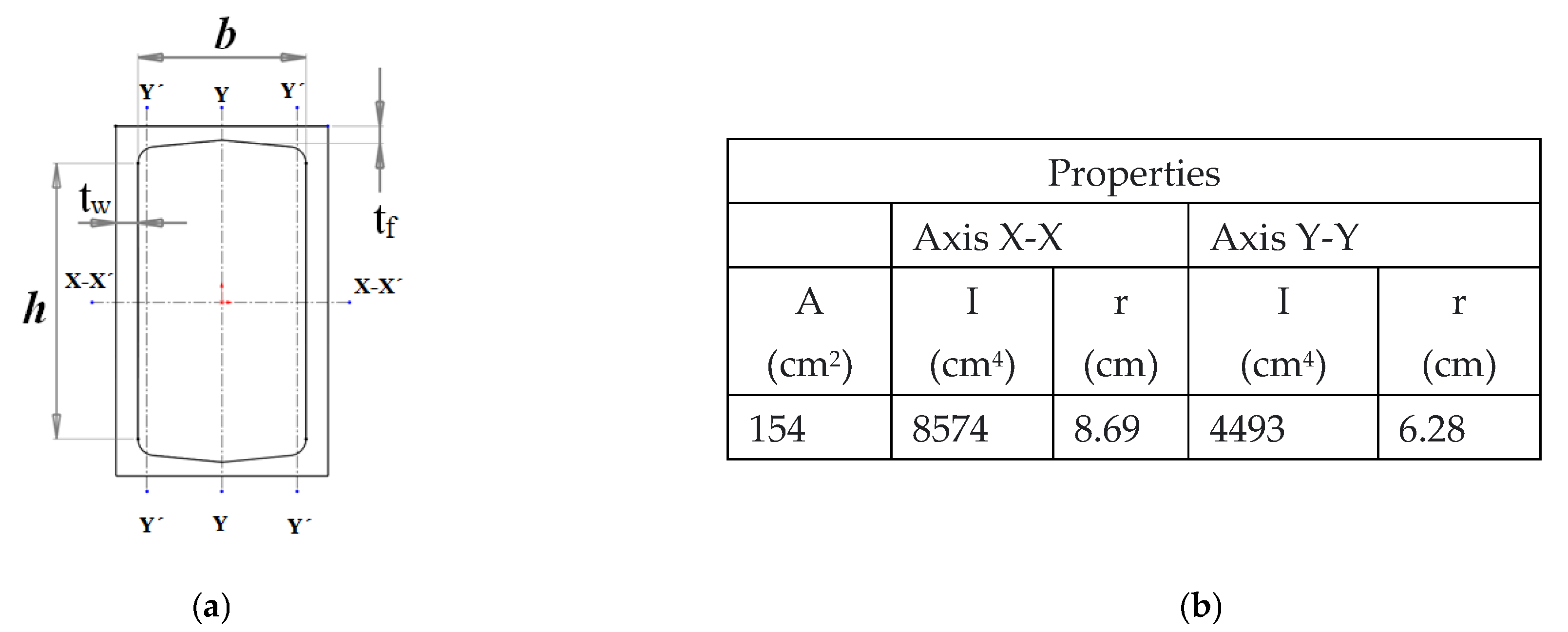
| Properties | Dimensions | |||||||||||
| Height × Weight | Dimensions | Properties | ||||||||||
| d (mm) | tw (mm) | Flange | m (mm) | T (mm) | Axis X-X | Axis Y-Y | ||||||
| Width
bf (mm) | Thickness
tf (mm) | A (cm2) | I (cm4) | r (cm) | I (cm4) | r (cm) | x (cm) | |||||
| C10×30 | 254 | 17.1 | 77.0 | 11.1 | 25.4 | 203 | 56.9 | 4287 | 8.69 | 164 | 1.70 | 1.65 |
| Description Element | Description Element | ) | |||||
|---|---|---|---|---|---|---|---|
| Flanges of rectangular HSS | b/tf = 10.87 | Webs of rectangular HSS | h/tw = 11.94 |
| Slenderness Calculation with Respect to X-X Axis | Slenderness Calculation with Respect to Y-Y Axis | ||||||||
|---|---|---|---|---|---|---|---|---|---|
| K | L (cm) | (cm) | rx (cm) | K | L (cm) | (cm) | ry (cm) | ||
| 1 | 1200 | 1200 | 15.38 | 78 | 0.7 | 300 | 210 | 6.8 | 33.43 |
Disclaimer/Publisher’s Note: The statements, opinions and data contained in all publications are solely those of the individual author(s) and contributor(s) and not of MDPI and/or the editor(s). MDPI and/or the editor(s) disclaim responsibility for any injury to people or property resulting from any ideas, methods, instructions or products referred to in the content. |
© 2023 by the authors. Licensee MDPI, Basel, Switzerland. This article is an open access article distributed under the terms and conditions of the Creative Commons Attribution (CC BY) license (https://creativecommons.org/licenses/by/4.0/).
Share and Cite
Ramirez-Martinez, A.; Barriga-Rodriguez, L.; Rodríguez-Olivares, N.A.; Soto-Cajiga, J.A. Horizontal Tensile Machine for Mechanical Tests Applicable to Suspension Clamps, Transmission Line Accessories, and Overhead Conductors. Machines 2023, 11, 554. https://doi.org/10.3390/machines11050554
Ramirez-Martinez A, Barriga-Rodriguez L, Rodríguez-Olivares NA, Soto-Cajiga JA. Horizontal Tensile Machine for Mechanical Tests Applicable to Suspension Clamps, Transmission Line Accessories, and Overhead Conductors. Machines. 2023; 11(5):554. https://doi.org/10.3390/machines11050554
Chicago/Turabian StyleRamirez-Martinez, Antonio, Leonardo Barriga-Rodriguez, Noe Amir Rodríguez-Olivares, and Jorge Alberto Soto-Cajiga. 2023. "Horizontal Tensile Machine for Mechanical Tests Applicable to Suspension Clamps, Transmission Line Accessories, and Overhead Conductors" Machines 11, no. 5: 554. https://doi.org/10.3390/machines11050554
APA StyleRamirez-Martinez, A., Barriga-Rodriguez, L., Rodríguez-Olivares, N. A., & Soto-Cajiga, J. A. (2023). Horizontal Tensile Machine for Mechanical Tests Applicable to Suspension Clamps, Transmission Line Accessories, and Overhead Conductors. Machines, 11(5), 554. https://doi.org/10.3390/machines11050554