1. Introduction
Cycloidal reducers ensure very high reduction ratios, in some cases exceeding values of 200:1. Among their advantages are the lack of gaps between the active elements, the fact that between these elements there is rolling and not sliding friction, high resistance to shocks and silent operation. All of these advantages have made them used in the automotive industry, in machine tools, robotics etc. [
1,
2,
3,
4].
One of the main parts of this type of reducer is the cycloidal disk, which has lobes that are in contact with the cylindrical surfaces of some bolts [
5].
The cycloidal disk has radial symmetry, its shape recommending it for machining with tools that generate by enwrapping, for example hob mills [
6,
7].
This type of tool has the advantage of high productivity, as well as an increased processing precision, due to the fact that the profile errors of the tool are transposed much less on the profile of the generated part.
K.S. Lin et al. [
8] approached kinematic errors and tolerance for cycloidal gear reducers. Geometry, accuracy and manufacturing parameters were studied using the gearing theory. The distribution of kinematic errors of cycloidal reducers was investigated using the Monte Carlo method. Based on the equation of the tooth surface of the cycloidal gear, G. Liu et al. [
9] performed a simulation of cycloidal tooth profiles using MATLAB software to establish the precision and accuracy of cycloidal gear transmission.
Modifications regarding the active form of the cycloidal disk, as well as studies related to kinematic errors, efficiency of reducers and gear damage were also made by other authors, such as I. Komorska [
10], R. Król [
11], H. Tariq [
12] and K. Olejarczyk [
13].
Other authors have studied the technology of generating helical surfaces end mill tools, P. Borla [
14], or with side mill tools, L. Zhou [
15].
Last but not least, a number of authors, among them, T.S. Lai [
16], Y. Peng et al. [
17] and C. Liu et al. [
18], focused on the calculation of the geometry of the active elements of this type of reducers.
There are three ways of obtaining machined surfaces frequently used in the technique. These surfaces can be obtained as trajectories of a point, as envelopes of successive positions of a body, or finally as envelopes of successive positions of a curve.
The first of the cases can be exemplified by turning, the second by milling, with front cylindrical tools or disk cutters, and the last case, by generation with rack-type tools, gear- shaped cutters or hob mills.
The generation of surfaces by milling is characterized by high productivity and by the fact that surfaces of a complicated shape can be obtained. The disadvantage of this processing method is that the precision and quality of the obtained surfaces depends, to a great extent, on the machine tool used and very expensive machine tools are needed for mass production.
Generation by enwrapping is characterized by high productivity and surface precision, comparable to those obtained by the previously presented method.
Another feature of this method is that the generated surface profile is obtained by a large number of cuts, which makes the shape errors of the cutting edge have a lower influence on the accuracy compared to the other generation modes.
Last but not least, used machine tools are much cheaper compared to the CNC machines required for milling operations.
However, enwrapping generation requires determination of the cutting tool profile, which profile will be a reciprocally enveloping curve with the generated profile of the part. This profiling step can be very laborious and is prone to introducing errors into the tool design process.
In order to improve tool profiling methods, alternatives to classical analytical methods have been developed.
These alternatives allow either a calculation that is easier to perform, but applicable only to a limited range of profiles, or a calculation with more general applicability but with a higher degree of approximation. In this paper, the advantages of the two alternatives are combined, an algorithm for the generation of surfaces known in analytical form being imagined and presented. The algorithm implies the determination of the active surface of the generating rack gear, which is reciprocally enwrapping to the active surface of the cycloidal disk [
19,
20,
21,
22,
23,
24].
The novelty of the algorithm, based on the determination of the intermediate surface, consists in the fact that it uses an innovative method for determining this surface, called the “virtual pole method” [
25,
26].
The “virtual pole” method is based on the Willis theorem and starts from the premise that: “a normal to the profile to be generated, taken through any point of it, will intersect the centrode associated with this profile” [
25,
26,
27,
28].
The method allows determining the enwrapping curve of an ordered curl of surfaces, generated in the rolling movement of two conjugated centrodes.
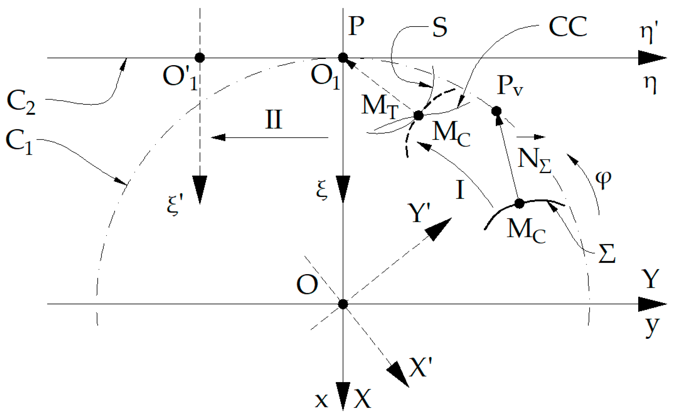
Figure 1 shows the reference systems used:
xy represents the fixed reference system, having the origin at point
O;
XY—mobile reference system, joined with the part;
ξη—mobile reference system, joined with the tool, with the origin at point
O1, as well as the centrodes
C1, associated with the part and
C2, associated with the tool.
The initial positions of the mobile systems associated with the part and the tool were denoted by XY and ξη and by X′Y′ and ξ′η′, the positions of the same systems after they were moved, so that the “virtual pole” Pv occupies the position of the gearing pole, P.
The position represented by a continuous line for Σ profile corresponds to the initial moment, while the position represented by a dashed line corresponds to the moment when the “virtual pole” overlaps the gearing pole.
The absolute movements by which the mobile reference systems move are: I represents the rotational movement of the XY system around point O and II—the translational movement of the ξη system along the η axis.
The intersection point between normal, taken to the profile to be generated Σ, and the centrode associated with the part is the “virtual pole”, Pv. Subsequently, by applying to the part the absolute movement that it performs during processing, the “virtual pole” is brought to the gearing pole, point P.
In this position, the current point MC, through which the normal to the profile was taken, is in contact with a point from the tool profile, point MT.
In addition, the tangency point between the tool profile S and the part profile Σ, the point MC≡MT, is, at this moment, on the contact curve CC.
Once the intermediate surface of the generating rack gear is known, its envelope is determined with a cylindrical and constant pitch helical surface, representing the primary peripheral surface of the worm tool.
This paper has a structure that consists of six main sections.
This section, Introduction, presents the state of art of the analyzed problem.
In
Section 2, Methodology for profiling the hob mill, the methodology used to develop the proposed algorithm for profiling the hob mill is presented, by using the intermediate surface method and the virtual pole method.
Section 3, Hob mill for processing the disk of a cycloidal reducer, develops the mathematical equations used to apply the algorithm in the case of the study of the enwrapping between a helical surface and a surface with radial symmetry. The stages of determining the equations of the theoretical cycloidal profile, establishing the position of the virtual pole, finding the enwrapping condition, identifying the intermediate surface and the primary peripheral surface of the hob mill tool are presented.
In
Section 4, Numerical application for profiling the hob mill for processing the disk of a cycloidal reducer, an example of a practical application of the proposed algorithm is presented. In the last column of ” the table were we present the coordinates of the points belonging to the profile to be generated and to the profile of the generating tool, in this section, the value of the equation of the winding condition is given for the numerical solution performed with the help of the
Octave program.
Since theoretically the value of the equation is zero, we can consider that the non-zero values represent errors in the identification of points on the intermediate surface. Considering the very low values obtained, we can state that the errors are negligible.
In
Section 5, an analysis and interpretation of the obtained results is made.
Section 6 is reserved for the presentation of established conclusions.
2. Methodology for Profiling the Hob Mill
The implementation of the proposed algorithm involves going through some predefined calculation stages.
First, the analytical equations of the profile to be generated are established, equations dependent on the parameter u.
Afterwards, the profile of the generating rack of this profile is determined. To achieve this stage, the equations of the virtual pole coordinates are determined based on the analytical equations of the previously determined profile.
Since the position of the virtual pole depends on the considered point on the profile to be generated and on the relative movement between the blank and the tool, its equations will depend on two independent parameters. One of them is the parameter u, which sets the position of the current point on the profile to be generated, and the other is the parameter φ, which sets the relative position between the tool and the workpiece.
Once the position equations of the virtual pole are determined, the enwrapping condition can be determined, which is actually a link between the two independent parameters, a link that only appears when the current point on the profile comes into contact with the cutting tool edge.
Thus, is determined the profile of the tool which will generate the desired profile of the piece. Due to the existence of the enwrapping condition, this profile again depends on a single parameter, respectively u.
The profile thus obtained will represent the generating curve of the intermediate surface, respectively the primary peripheral surface of the rack tool.
The analytical solution of the winding condition may be impossible to find, if it represents a transcendental equation, and therefore, in the paper, a method of numerical solution of this condition is proposed.
The proposed solution involves the use of the “fzero” function provided by the Octave program.
This command allows finding the value of the variable for which a given objective function has a value close to zero. Basically, the command performs an iterative calculation of the values of the objective function, between two given values of the variable and returns both the value of the variable and the value of the function corresponding to this variable.
The continuation of the algorithm involves the determination of the characteristic curve on the intermediate surface. As is known, according to the Nikolaev theorem, “the characteristic curve of a cylindrical surface, reciprocally enwrapping with a cylindrical helical surface of constant pitch, is the geometric locus of the points where the normal to the cylindrical surface intersects the axis of the helical surface” [
25,
29].
The analytical solution of the characteristic curve equations is much more complicated, often requiring a numerical solution.
According to the proposed algorithm, the intermediate surface is approximated by a cloud of points whose coordinates are known in discrete form.
According to the Nikolaev theorem, among the points belonging to this cloud, will also belong to the characteristic curve, only those points where the normal to the surface intersects the axis of the tool.
The identification of these points is done by fixing two of the coordinates of the points and solving the enwrapping condition for the third coordinate.
After finding the characteristic curve, a helical motion is given on it, generating the primary peripheral surface of the hob mill tool.
The axial section of the tool is determined by intersecting the primary peripheral surface with an axial plane.
In the following, these stages are detailed from a mathematical point of view.
3. Hob Mill for Processing the Disk of a Cycloidal Reducer
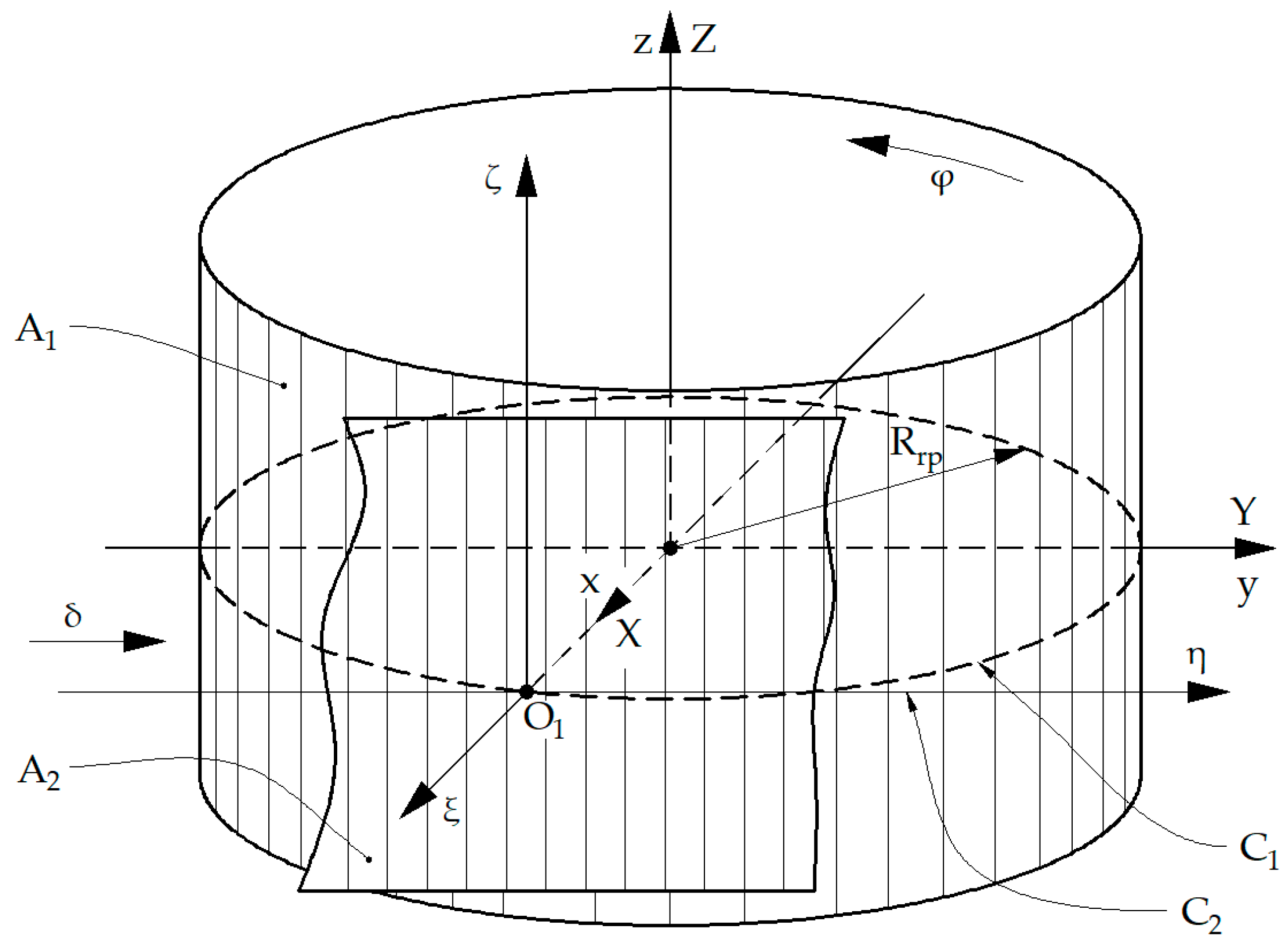
Figure 2 shows the generation with the rack gear tool, the reference systems, as well as the conjugated axodes.
The following are defined: A1—axode of the part; A2—axode of the rack gear tool; xyz—the fixed reference system, having the z axis superimposed on the axis of the A1 axode; XYZ—the mobile reference system, joined with the part, the Z axis being superimposed on the z axis of the fixed system; ξηζ mobile reference system, joined with the tool. The A2 axode belongs to the plane determined by the η and ζ axes.
The observation is made that the projection in the XY plane of the A1 axode is the C1 centrode, a circle of radius Rrp, and the projection in the ξη plane of the A2 axode determines the C2 centrode, which is a line.
The kinematics of the rolling process of the two axodes respects the rolling condition:
where
Rrp represents the rolling radius of the blank and
φ the rotation angle of the reference system associated with the profile to be generated.
The absolute movements that occur during rolling are:
- -
the rotation of the C1 centrode around z axis, rotation having the angular parameter φ:
where
is the rotation matrix.
- -
the translation of the C2 centrode in a parallel direction to the y axis:
where
A represents the translation matrix and
δ—the translation of the reference system, joined with the rack gear tool.
3.1. Equations of the Theoretical Cycloidal Profile
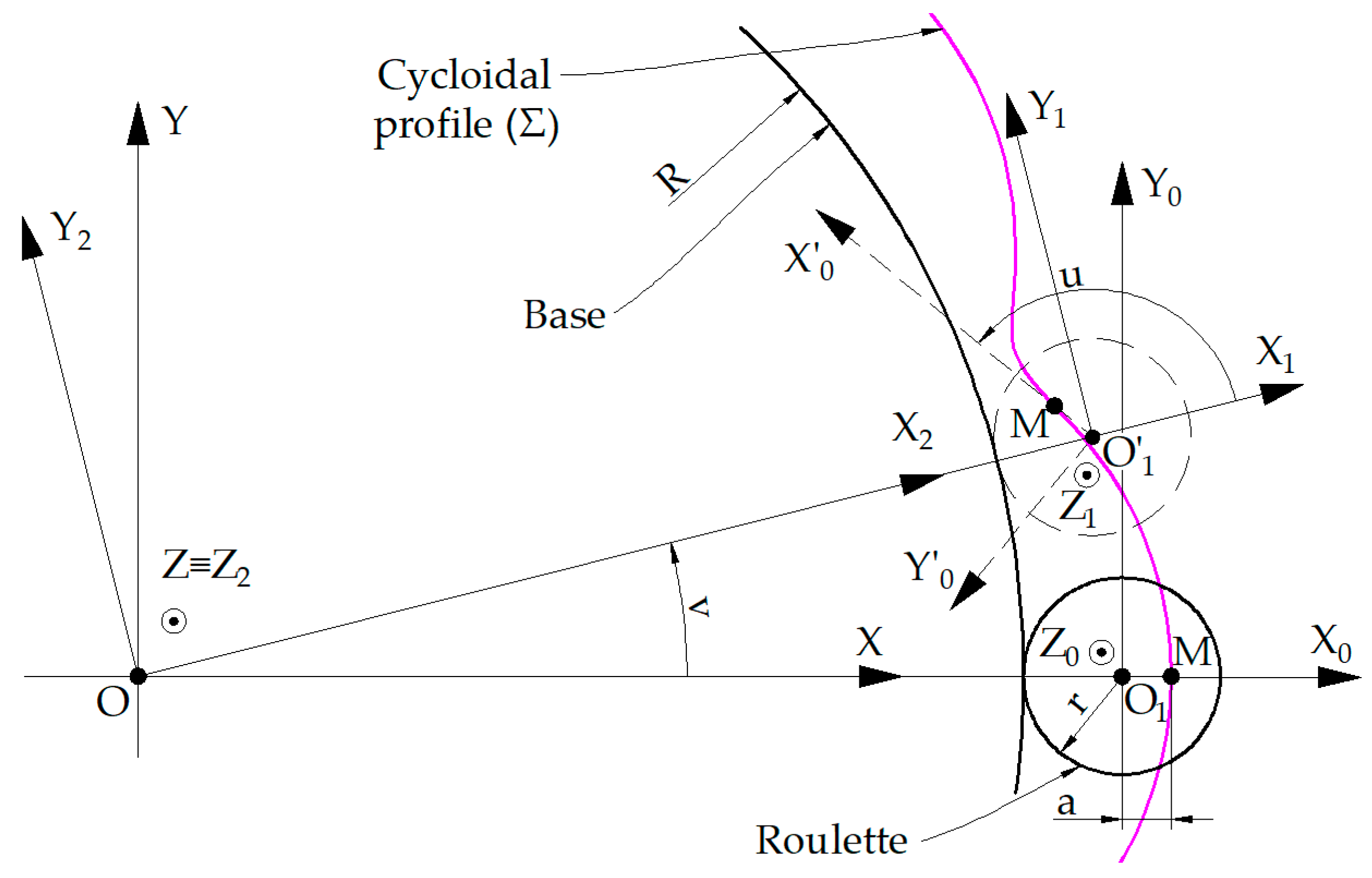
The cycloidal profile is described by a point
M, joined with a circle of radius
r (roulette radius), which rolls outside the base, with a circle of radius
R (base radius),
Figure 3 [
21].
Four reference systems will be used to identify the cycloidal profile:
- -
X0Y0Z0 is the reference system in which the coordinates of M point are defined; the roulette is defined in this reference system;
- -
X1Y1Z1—the reference system with the same origin as the X0Y0Z0 system, which rotates around the Z0 axis with the angular parameter u (variable parameter which describes the profile of the part); in this way, the M point describes a circle of radius a (the distance between the generating point of the cycloidal profile and the center of the roulette);
- -
X2Y2Z2—mobile reference system having the axes X2||X1; Y2||Y1; Z2||Z1 and the origin O offset from the O1 with the value (R + r);
- -
XYZ—the mobile reference system, joined with the profile to be generated Σ; the Z axis coincides with the Z2 axis and the X2Y2Z2 system rotates towards to the XYZ system, around the Z≡Z2 axis, with the angle v (the rotation parameter of the X2Y2 reference system).
In
Figure 3, the position indicated by the continuous line for the roulette corresponds to the initial moment, while the position indicated by the dashed line corresponds to a rotation with an angle of v ≠ 0. The same observation applies to the axes of the reference system, the axes being the notation for the new axes position
X0Y0Z0.
The cycloidal profile is a plane curve, therefore, generating this profile and determining the profile of the rack gear tool, which generates the ΣT profile, can be treated as a plane enwrapping problem and can be studied in the XY plane.
Point
M has the following coordinates:
In the relative movement of system
X0Y0 to system
X1Y1,
which, developed, can be written:
the
M point describes the circle of equations:
The coordinate transformation between the reference systems
X2Y2 and
X1Y1 is:
or, developed:
Therefore, in the
X2Y2 system, the trajectory of point
M will be a plane curve:
The movement of the
X2Y2 system with towards to the
XY system is given by the equation:
which can be developed by the form:
The transmission ratio is defined as
and, taking into account the rolling condition of the roulette with towards to the base, it results:
from Equation (12), the cycloidal profile equations are obtained:
Note: For the cycloidal profile to be a closed curve, the condition must be respected, i = n, n being an integer number.
3.2. Determining the Position of the ”Virtual Pole”
The direction of the normal to the
ΣT profile is given by the equation:
In Equation (15)
and
represents the partial derivatives of the equations
X(
u) and
Y(
u) (Equation (14)) in relation to the
u variable:
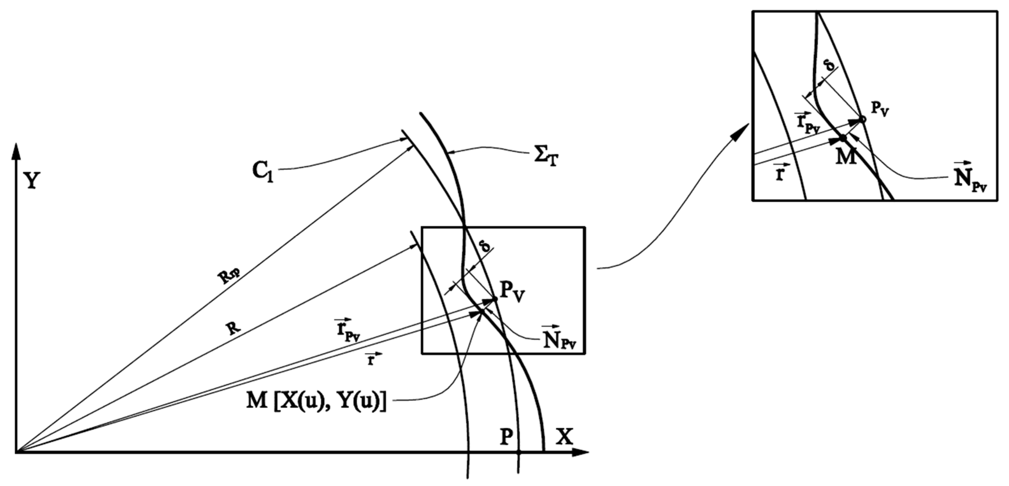
The normal to the
ΣT profile intersects the
C1 circle, of
Rrp radius, at the distance
λ from the current point
M, of coordinates
X(
u),
Y(
u),
Figure 4 [
22].
Therefore, the
vector, the normal vector, with the origin at the current point on the
ΣT profile and with the top in the “virtual pole” (belonging to the circle of radius
Rrp), has the equation:
At the same time, the position vector of the current point
M is:
Thus, the position vector of the
Pv point is obtained by summing the vectors
and
In principle, the
vector can be written as follows:
Taking into account the fact that the point
Pv also belongs to the circle of radius
Rrp, with the equations:
the coordinates of the “virtual pole” point can be obtained from the Equations (19) and (21), in the form:
3.3. Determination of the Enwrapping Condition
The enwrapping condition must be determined as a relation between the independent parameters u and φ, so that the profile of the generating rack gear is the enveloping curve for the family of curves obtained during the relative movement of the XY system towards to the ξη system.
If the parameter
λ is removed from the system of Equation (22),
the specific form of the enwrapping condition is obtained:
Basically, the equation (24) represents a dependency of type:
3.4. Determination of the Intermediate Surface
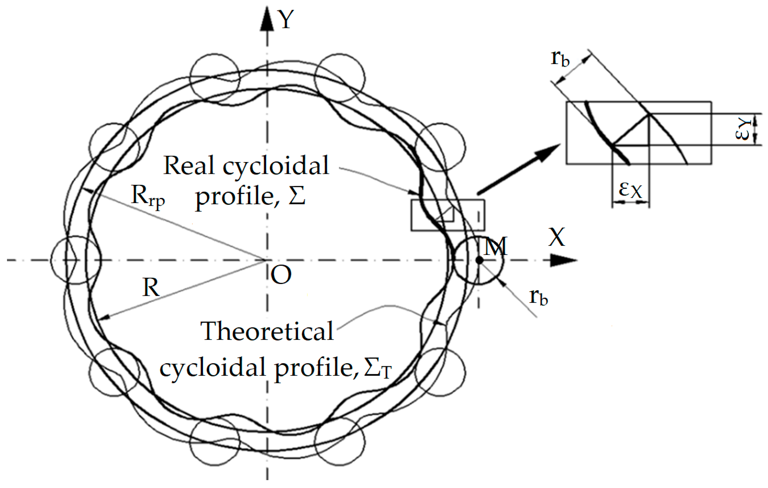
It should be taken into account that the active profile of the disk from the cycloidal reducer is an equidistant curve to the theoretical cycloid given by Equation (14) [
26,
27].
The distance at which the real profile is compared to the theoretical profile is equal to the radius of the bolts, rb, which materializes the inner gearing surface.
Figure 5 shows the theoretical cycloidal profile and the real profile.
The equations of the real profile are:
where
εX and
εY represent the distances between the real and theoretical profiles measured along the
X and
Y directions:
For a certain value of the parameter
u,
Figure 6 and
Figure 7, the coordinates of the current point
M can be determined in the form:
If the enwrapping condition (24) is taken into account, the coordinates of the same point M can be determined at the moment when the “virtual pole” coincides with the gearing pole, therefore, when P belongs simultaneously to the three curves: the profile to be generated, the contact curve (CC) and the profile of the generating tool (S).
The coordinates of the
M point on the contact curve, in the fixed reference system, are obtained from the absolute movement of the part (2), where
φ is given by the Equation (25):
When the parameter
u takes values between the limits
umin and
umax, so that the current point
M describes the entire profile
Σ, the contact curve,
CC, is obtained in the form:
Taking into account the absolute movement of the tool (3), and the coordinates of the current point
M in the fixed reference system, the coordinates of the same point are obtained in the reference system associated with the rack gear tool:
As in the case of determining the contact curve (30), the parameter
u is assigned a variation between the limits
umin and
umax, obtaining the equations of the generating tool profile:
Note: It is worth emphasizing that the profile was determined without the need to write the relative movements between the tool and the blank. Of course, the influence of these movements is not canceled, but the “virtual pole” method allows avoiding the need to write the respective movements.
The intermediate surface will be the surface generated by the rack gear profile during the main movement performed by the tool.
Considering that the main movement, when generating with the rack gear tool, is an alternative rectilinear movement, having the direction parallel to the direction of the surface to be generated, in the case of processing the cycloidal disk, the intermediate surface will have as a generator the planar curve
S, represented by the profile of the tool, and as directories, the
ζ axis,
Figure 6.
Therefore, the equations of the intermediate surface are:
where
t represents an independent variable parameter.
3.5. Determination of the Hob Mill Primary Peripheral Surface
The primary peripheral surface of the generator worm is a cylindrical helical surface of constant pitch and is reciprocally enwrapping with the intermediate surface, SI.
To determine the primary peripheral surface of the screw, it is necessary to determine the characteristic curve, the contact curve between the intermediate surface and the helical surface of the worm.
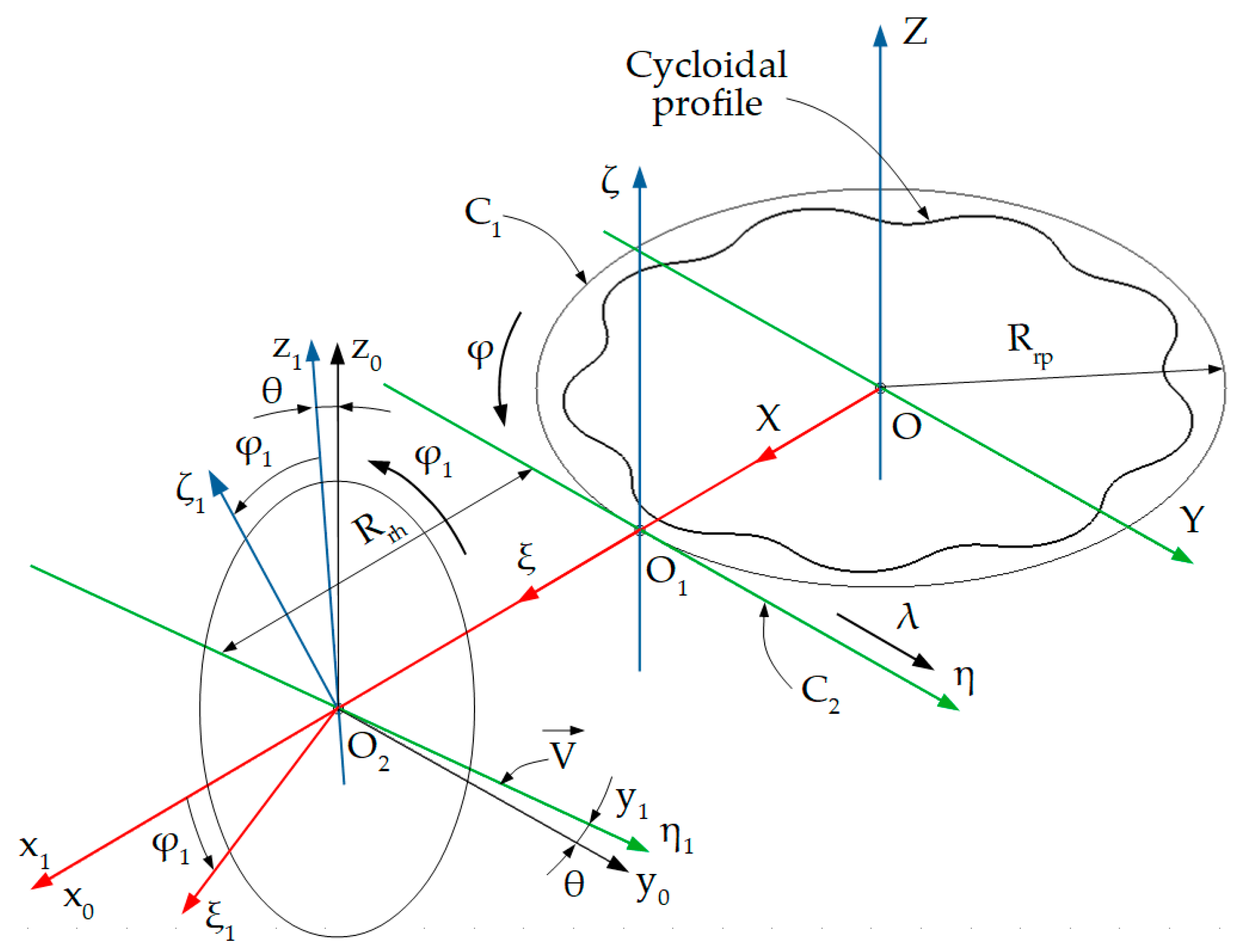
For this purpose, four reference systems will be used,
Figure 6:
- -
ξηζ is the reference system joined with the rack gear, with the origin in O1, system in which the intermediate surface is defined;
- -
x0y0z0—the mobile reference system, having the axes parallel to those of the ξηζ system and the origin O2 displaced towards to it by the value Rrh, along the x0 axis; where Rrh represents the rolling radius of the hob tool, constructive size;
- -
x1y1z1—the mobile reference system, having the y1 axis parallel to the axis of the helical surface of the hob and the x1 axis superimposed on the x0 axis;
- -
ξ1η1ζ1—the reference system joined with the hob tool, having the η1 axis superimposed on the axis of the hob,
In
Figure 6,
θ angle represents the angle by which the axis of the worm is rotated towards to the
η1 axis, the
η1 axis being parallel to the
η axis. This angle represents the rotation angle around the
x1 axis.
The coordinate transformation is defined between the
ξηζ and
x0y0z0 coordinate systems:
or, developed:
In Equation (34), B represents the position vector of the origin of the system ξηζ in the reference system x0y0z0.
The distance between the origins of the
XYZ and
x0y0z0 reference systems is given by the relation:
According to the intermediate surface method, resulting from the Nikolaev theorem: “The characteristic curve of a cylindrical surface, reciprocally enwrapping with a cylindrical helical surface of constant pitch, is the geometric locus of the points where the normal to the cylindrical surface intersects the axis of the helical surface.” [
22,
29].
The generator
S of the intermediate surface
SI is discretely known in the form:
The intermediate surface
SI will be approximated with a surface family of the plane stripe type, determined by displacing the segments
ξiηi along a direction parallel with the
ζ axis,
Figure 7.
In this way, the intermediate surface can be approximated by a cloud of points known in discrete form:
where
SIa represents the intermediate surface approximated by the point cloud known in discrete form, and
u1 and
hi are independent variable parameters.
In Equation (38),
αi represents the inclination angle of the segment that approximates the profile of the rack gear tool and is determined with the relation:
The normal to the approximate surface, taken to any of its known points, will have the form:
At the same time, the
axis of the helical surface, in the
ξηζ system, has the form:
with
t independent parameter and
θ the inclination angle of the hob curl.
The value of the
θ angle results from the relation:
where
pm represents the axial pitch of the helical surface.
The pitch of the helical surface can be calculated using the Equation:
n being the number of the cam lobes.
From Equations (40) and (41), the coordinates of the intersection point between the normal to the approximate intermediate surface,
and the axis of the helical surface,
can be determined:
From Equation (44) results:
Equation (45) allows determining the coordinates of a characteristic point, meaning a contact point between the approximate cylindrical surface and the helical surface
PC, in the form:
When
i = 1 ÷
n, the characteristic curve in discrete form,
CCm, is determined:
In order to determine the primary peripheral surface of the worm tool, it is necessary that this characteristic curve to be expressed in the x1y1z1 reference system and given a helical movement of axis and helical parameter pe, in the ξ1η1ζ1 system.
The coordinate transformation from the
ξηζ reference system to the
x1y1z1 reference system is obtained by passing through the transformation (34), then:
where
The helical movement of
axis the helical parameter
pe is:
where
φ1 represents the rotation angle of the reference system
x1y1z1, towards to the reference system
ξ1η1ζ1, see
Figure 6,
and
.
Therefore, the equation of the primary peripheral surface of the hob tool can be written:
or, developed,
By equalizing
the value of the
φ1 parameter is obtained, for which the points on the
SM surface also belong to the axial section:
so:
Therefore, the axial section of the primary peripheral surface of the hob mill tool is obtained, in the form:
4. Numerical Application for Profiling the Hob Mill for Processing the Disk of a Cycloidal Reducer
A numerical application was made for the profiled disk of a cycloidal reducer. The disk has the dimensions shown in
Table 1, with the following notations:
R—radius of the base;
r—radius of the roulette;
a—the distance between the generating point of the cycloid and the center of the roulette;
rb—radius of the bolts;
Rrp—rolling radius of the blank;
Rhr—rotation radius of the worm (value chosen constructively).
The calculation application was made in the Octave program, a software product designed to realize numerical calculations, in general for solving systems of equations with linear algebra operations on vectors and matrices.
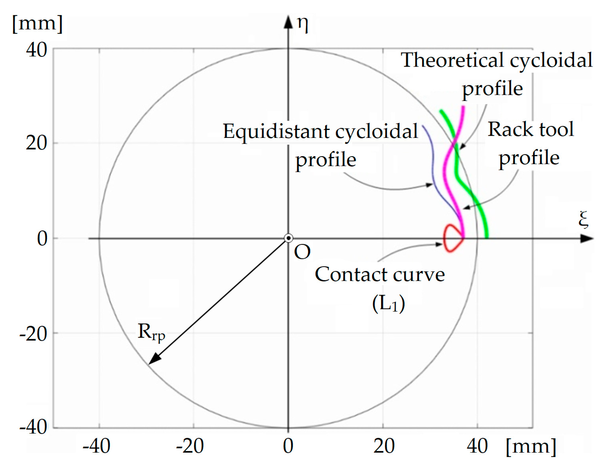
By running the calculation program, the theoretical profile of the cycloid, the curve equidistant to this profile and the profile of the generating rack gear tool were obtained,
Figure 8.
The enwrapping condition will have the specific form given by the Equation (24). To solve this equation, the “fzero” function from the Octave program is used [
30]. This function allows finding the solution of an equation of
f(
u) = 0 type.
Table 2 shows the coordinates of the points belonging to the profile to be generated and the coordinates of the points belonging to the profile of the generator rack gear tool.
To demonstrate the accuracy of identifying the solution for the enwrapping condition, in the same table, for each value of the variable u, the value of this condition is given, found using the ”fzero” function.
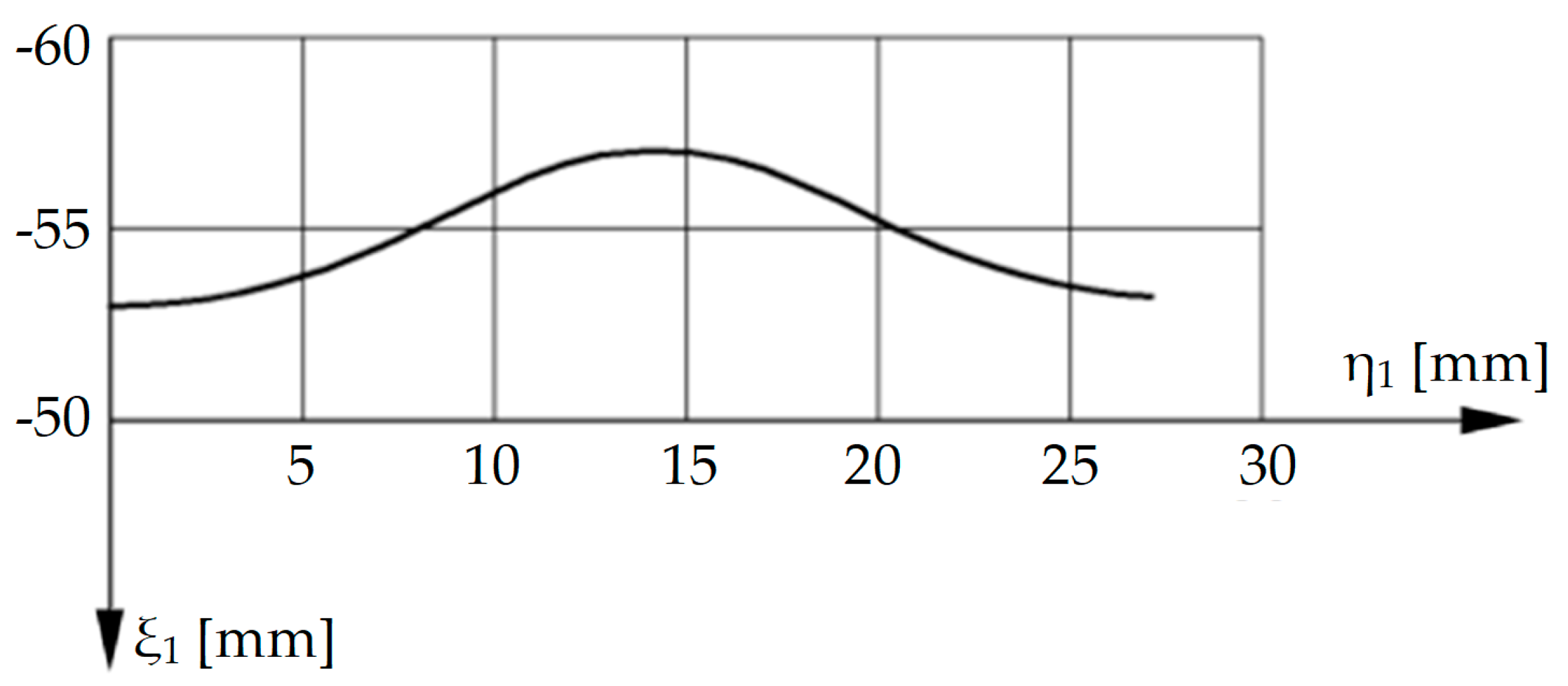
Applying the algorithm described in
Section 3.5, the primary peripheral surface of the hob mill tool is identified.
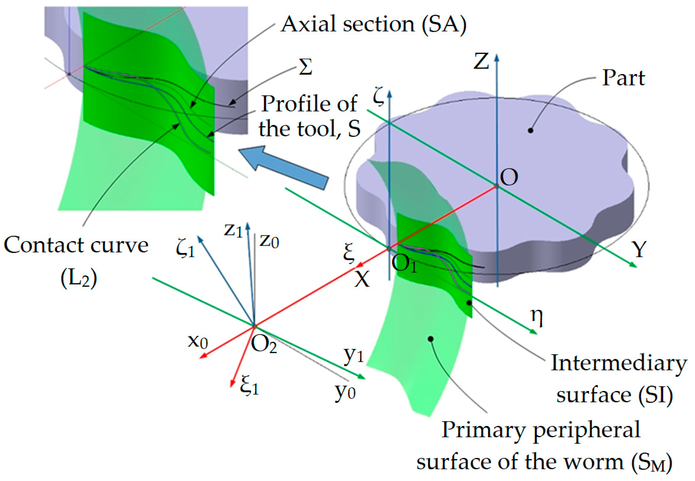
In
Figure 9, the intermediate surface of the generating rack gear tool, the primary peripheral surface of the hob and the characteristic curve are represented, and in
Table 3 the coordinates of some of the points belonging to the characteristic curve and the axial section of the hob are presented.
If the contact curve between the active surface of the cycloidal disk and the intermediate surface is denoted by
L1 (
Figure 8) and the contact curve between the intermediate surface and the primary peripheral surface of the hob tool is denoted by
L2 (
Figure 9), the intersection point of the two curves represents the characteristic point, meaning the contact point between the cylindrical surface of the cycloidal disk and the primary peripheral surface of the worm tool.
The axial section of the generating hob, obtained by applying the Equation (54), is shown in
Figure 10.
5. Analysis of the Results
The profile of the cycloidal disc was determined by assigning the variable u values in the range 0 ÷ 2·π. For each value, the X, Y coordinates were calculated, using equations (28).
To determine the enwrapping condition, the values of the variable φ were determined which, together with the corresponding u value, determines a value close to 0 of the function (28). Thus, the pairs of independent variables (u, φ) that determine points on the contact curve were determined.
As mentioned in
Section 2, the determination of the values of the variable
φ was done using the function “fzero”, which returns the point where the objective function has a value close to zero, as well as the value of the objective function at that point.
Given that for a point located exactly on the contact curve, the value of the objective function (of the wrapping condition) is zero, non-zero values of this function can be regarded as contact curve determination errors.
As can be noted in
Table 2, where the values of the winding condition are presented, these errors are sufficiently small, having values below 2 × 10
−13 mm. We consider that these errors are small enough to be negligible in practice.
Another approximation used within this algorithm is the one using the intermediate surface in discrete form, presented in the form (37).
Through this approximation, the plane curve that represents the generator of the intermediate surface is replaced by a set of segments whose extremities are located on that curve.
The greater the number of segments by which the intermediate surface generator is replaced, the better its approximation will be.
6. Conclusions
In the paper, the profiling of the hob mill tool designed to generate the active surface of the cam of a cycloidal reducer was presented. The algorithm was based on the determination of an intermediate surface, belonging to the generating rack gear, which is reciprocally enwrapping to the surface of the cycloidal disk, the profiling algorithm using the advantages of the “virtual pole” method.
The proposed algorithm uses the intermediate surface method which involves determining the characteristic curve on a helical surface, mutually wrapping with a surface with radial symmetry.
In the analysed case, the helical surface is the primary peripheral surface of the hob mill, and the radially symmetrical surface is the active surface of the cycloidal disk.
The contact is studied on an intermediate surface that can be viewed, from a generation point of view, as the primary peripheral surface of a virtual rack tool, profiled to generate the target surface (the active surface of the cycloidal disc).
By the “virtual pole” method, the analytical form of the enwrapping condition is determined. Since the analytical form of the system of Equation (30) leads to transcendental equations, it is necessary to solve it numerically, using the mathematical facilities of the Octave program.
The numerical solution inevitably introduces an inaccuracy, but this is small enough to be negligible. The level of errors, for each of the points where the winding condition is calculated, is presented in the last column of
Table 2, it can be noted that the maximum error is 1.95 × 10
−13 mm.
After determining the intermediate surface, it is used to establish the characteristic curve, known as the contact curve between a cylindrical surface and a helical surface.
Normally, the determination of this curve is also particularly difficult, however, making the observation that for each point of the curve two of the coordinates are known, the coordinates ξ and η on the intermediate surface, all that remains is to determine the coordinate ζ that satisfies the system of Equation (44).
In this way, the characteristic curve is determined in the form of a cloud of points, a practically usable form for making the desired tool.
By using the virtual pole method in the step of determining the intermediate surface, the need to find analytical equations describing the relative motion between this surface and the surface to be generated was eliminated.
Since relative motion leads to complicated equations specific to each shape of the surface to be generated, avoiding writing them greatly simplifies the computational effort and eliminates a possible source of error introduced during the tool design stage.
The aim of the work was to demonstrate the possibility of practical application of the virtual pole method to the design of hob mill tools and the numerical applications made in Octave and CATIA demonstrate this.
Thus, the analytical equations of the cycloidal profile were known and the profiling of the hob mill tool was realized. The intermediate surface was approximated with a family of surfaces of plane stripe types, which were determined by approximating the generating curve with a cloud of points known in discrete form.
At the same time, numerical applications were made, in the Octave and CATIA programs, for profiling of the worm tool designed for processing the active surface of the cam of a cycloidal reducer, reaching the conclusion that the calculation time for tools profiling is thus significantly reduced. The given disadvantage of the resulting error is small enough to be technically acceptable and is fully compensated by this reduction in calculation time, the resulting error coming from replacing the intermediate surface with an approximate surface by strips (the normal being a curve, and it was approximated by a line segment).
