Abstract
The compliant mechanism (CM)-based fast-tool servo (FTS) is used in ultraprecision machining contexts to produce high value products for technically advanced applications. Far too often, the FTS’ machined products are expected to be geometrically complex with minimal form tolerance and surface roughness. Since the FTS’ enclosing CM is responsible for guiding the cutting motion, its design is of utmost importance in determining the quality of the machined product. The objective of this paper is therefore to review specifically the design and structural related aspects of CM-based FTS that affects its ultraprecision machining performance. After a brief introduction, the fundamentals for designing ultraprecision capable CMs such as flexure hinge modelling, actuator selection and isolation and CM designing are comprehensively explained. In the subsequent section, the various configurations of CM-based FTSs that exist so far and their functionalities are listed. The critical factors which impact the CM-based FTS’ ultraprecision machining performance are identified and mitigating measures are provided wherever possible. Before concluding, the research questions that should be investigated for raising the state of the art of CM-based FTSs are presented as food for thought. With this review article, not only can practitioners have a clearer picture of how better to design their CMs for their FTSs, but they can also improve upon existing FTS designs from leading researchers so that products of higher quality than before can be made for the future.
1. Introduction
A spring contracts under an impact loading for achieving a dampening effect, and a recurve bow converts elastic energy into kinetic energy for its projectiles the moment it is drawn [1]. Both revert to their equilibrium positions right after those flexing deformation. These are in fact, examples of the most intuitive forms of compliant mechanisms (CM) that one can think of where structural flexing is performed for achieving a user defined functionality [2]. The CM’s technical definition is a structure whose strain arising from an elastic deformation is used for force transmission purposes. Since this strain has excellent repeatability, zero backlashes, friction and wear [3], CMs are often preferred over conventional rigid mechanisms [4], especially for precision applications.
Fields ranging from biomedical to microelectromechanical systems have extensively used CMs with varying designs and features [5]. Figure 1 shows selected instances where CMs have proven to be useful over their rigid body counterparts. Using a compliant u-shaped spring instead of the usual cantilevered beams, Olesnavage et al. were able to devise a prosthetic foot of higher stiffness and range of motion for the ankle [6]. Pick-and-place devices for organic objects such as fruits with conventional rigid mechanisms tend to cause bruised surfaces. Miao and Zheng addressed this issue by developing a constant force CM apple picking actuator that provides a much softer grip [7]. CM morphing wings have also been experimentally verified to be able to deflect and modify the chord of an airfoil at a much larger range compared to regular types [8]. U-shaped CMs have also been explored as alternatives to bimetallic strips in miniaturized circuit breakers since they are more resilient against cyclically loaded magnetic forces arising from alternating current flows [9]. Bistable CMs have been developed as shock sensors that need no power supply for use in crash logging, material handling and shipment monitoring [10]. Beam steering often required for solar tracking purposes has also benefitted from the use of CMs as suitable alternatives to bulky mechanical polygonal mirror scanners [11]. Compliant serial-parallel mechanisms that can provide highly fluidic motions have also been used in fish-like robots [12]. With compliant mechanisms, the robot fish can produce vectoring and thrust forces more fluidly to mimic a real fish. While these examples adequately highlight the versatility of CMs for everyday general usage, precision design considerations are required before they are deemed suitable for ultraprecision use, where output is expected to be at a micro or nanometric scale.
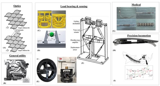
Figure 1.
Examples of CMs in the clockwise direction. (A)Optical beam reflecting [11]; (B) Miniature circuit breakers [9]; (C) Load bearing deployable structure [13]; (D) Constant-force fruit picker [7]; (E) Anti-buckling universal joint [14]; (F) Electromagnetic force balance sensor [15]; (G) A self-expanding stent [16]; (H) Morphing flight wing [8]; (I) Robotic fish [12].
As society becomes more reliant on microstructures with the advancement of technology, high quality throughput of precision components become more desired. This well positions ultraprecision machining (UPM) technology to directly produce components and molds of optical quality, with excellent surface finishing and mirror surface finishing [17,18]. In infrared or short wavelength applications, these optical structures require form accuracies less than 100 nanometers from their designed surface [19], while larger optical components greater than 1 m require surface accuracies of below 8 microns and subsurface damage of fewer than 3 microns [20]. With the increasing complexity of optical structures and requirements, many efforts have been focused on manipulating the tool to create these structures. Brinksmeier et al. developed the Diamond Micro Chiseling (DMC) technique to reposition the tool accurately to create facets in various orientations to develop large arrays of retroreflectors [21]. Huang et al. demonstrated the ability for high fidelity generation of images by creating greyscale images using inverted pyramids with relative cell aperture sizes [22]. Zhang et al. included an additional rotational axis to enable the Rotating tool Diamond Turning (RDT) to fabricate circular Fresnel lenses on the curved surfaces of roller molds [23]. Many researchers have also employed various techniques to fabricate freeform polygonal Fresnel lenses, including Neo at al. with the Automated Guilloche Machining Technique (AGMT) for hexagonal Fresnel lenses [24] and Tan et al. using Direct Diamond Shaping (DDS) of composite polygonal Fresnel lenses [25]. While much work has been carried out to improve the efficiency when machining such complex features, the response from these Slow Slide Servo (SSS) techniques is usually low, limiting the operational frequencies when machining structures with much topological variation [26,27,28].
For producing high density microstructures within a small area on the workpiece [29], conventional CNC machines have difficulty synchronizing a fast rotating spindle with the required high frequency reciprocating motions of the turning tool. This is due to such machining processes requiring a large force, stiffness, response adequate stroke, zero backlash and repeatability which are beyond the CNC’s servo capability [30]. For surmounting those concerns, CM-based fast tool servos (FTS) that remove surface material on a workpiece in rapid and consistently traceable back-and-forth motions are used in single point diamond turning (SPDT). The two common manners in which the FTS is used for machining are shown in Figure 2. On the left, the FTS is used for diamond facing where it is machining in a back-and-forth motion parallel to the workpiece’s central axis whereas, on the right, the FTS is machining perpendicular to the axis in a roll machining process.
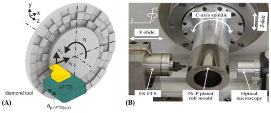
Figure 2.
Fast tool servo examples. (A) Process schematic of FTS machining during SPDT [31]; (B) A FTS machine setup for machining on a roll mold [32]. For Figure 2B, readers should take note that the spindle rotation should ideally not be referred to as the C-axis if the cutting motion is provided by its rotation. Spindle rotation can be termed as C-axis if it performs indexing motion such as those in mill turn machining centers.
By using the FTS, products with tessellated micro/nanostructures on their surfaces as shown in Figure 3 can be produced more effectively as compared to lithographic processes. Microstructure morphologies that are possible with the FTS include sinusoidal microlenses [33,34] and square pits [35] shown in Figure 3A,B. Complex surfaces that are non-rotationally symmetric freeform or of toric forms [36] are also usually machined using the FTS. The spherical and aspherical surfaces which find use in advanced photonics and imaging purposes [37] are also manufactured using the FTS. The FTS has also proved its versatility by machining a complex freeform surfaced femoral head prosthesis [38] and microstructured molds with square microstructures [31].

Figure 3.
FTS machined workpiece examples. (A) FTS machined microstructured mold with a PMMA (polymethacrylate) surface embossed by the mold shown at right [31]; (B) Microlens array [39].
The FTS machining tool consists of both CM and non-CM components such as the computer, servo control panel, power amplifier, actuators and sensors [40]. Past reviews on FTSs focus either on their non-CM aspects or on the surfaces they fabricate. Gong et al. had made comparisons between two control algorithms commonly used for FTSs, namely the PID and hybrid control algorithms, and discussed how accurately each performed microstructure machining [41]. A review article by Zhu et al. examines non-CM aspects of the FTS such as its machining processes, closed loop controls, toolpath programming and surface metrology for the manufacturing of optical freeform surfaces [40]. Brinksmeier et al. also review FTSs but more on the surface structures they are capable of machining [42]. A separate review on surface structures also touched on the nano FTS but again, had very minimal mention of how CM design contributes to its functionality [43]. Finally, the FTS was reviewed by Zhang et al. from a machining point of view which had marginal consideration of how CM design might affect machining performance [44]. Despite the CM being a key component of the FTS, there is not much literature on how its design can aid in ultraprecision machining. This gap may contribute to limited functionalities in CM-based FTSs as only through design variations novel functionalities such as long stroke, motion decoupling, actuator isolation and real time machining measurements be made possible. In fact, Zhu et al. promoted in their review article the use of multi DOF or rotary FTSs, which are of greater design complexity, for overcoming the machining limitations of the linear FTS [40].
This review is geared towards the design and structural aspects of the FTS’ CM that is crucial for attaining ultraprecision accuracy and flexibility. In Section 2, the design related prerequisites for CM-based FTSs are comprehensively reviewed. Matters related to flexure hinge fundamentals, motion decoupling, displacement amplification structures, actuators and actuator isolation, design methodologies, CM-based FTSs prototyping concerns and the various configurations that researchers have developed and experimentally verified are included in Section 2. The accompanying Section 3 will explain how factors such as machining parameters and CM structure related factors such as stiffness, dynamic behavior, hysteresis, fatigue and thermal conductance will affect the FTS’ machining performance. Before concluding, the possible future research direction for the design and application of CM-based FTSs will be considered.
2. Designing Ultraprecision Capable CMs
Unlike a conventional machining tool which consists of interconnected rigid body mechanisms such as gears, pins and hinges moving against each other [45] for providing the cutting action, the CM-based FTS is monolithically designed to consist of flexure hinges, sensors and at least one actuator. The flexure hinges used for FTSs are mostly based on the basic notch and bladed types (shown in Figure 4) [46]. The notch hinge only rotates about an axis at its thinnest section whereas the bladed hinge can rotate and twist about itself.

Figure 4.
(A) Notch hinge; (B) Blade hinge; (C) Elliptical hinge.
For reliable ultraprecision machining, the output stiffness, natural frequencies, and output displacement accuracy of the CMs are ideally designed to be as high as possible. On the other hand, mounting options should also be accounted for when developing FTSs for retrofitting onto existing machines.
CMs can be designed either in serial or parallel configurations with key differences lying in mass, ease of mathematical modelling, range of motion [47] and first mode frequency. Figure 5A shows a typical serial configuration with a chain of flexure hinges [48] and Figure 5B shows a parallelogram flexure module which is a parallel CM type [49]. It should be noted that serial configurations generally have lower working bandwidth between cutting displacement and frequency than parallel configuration CMs.
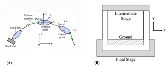
Figure 5.
(A) Serial CM [48]; (B) Parallel CM-based parallelogram flexure unit [49].
2.1. Fundamental Flexure Hinge Modelling
The overall compliance of the CM is dependent on each of its flexure hinge’s stiffness. Each flexure hinge is geometrically defined by its web thickness, in-plane thickness and its hinge radius, as shown in Figure 6, and together with the hinge’s material properties, they determine the stiffness of the hinge. Aravind et al. have identified that increasing the hinge’s in-plane thickness and web thickness raises its bending stiffness while increasing its curvature brings about the opposite effect [50]. Formulaically, the stiffness of the circular and elliptical hinge can also be approximated using Equations (1) and (2) [51].
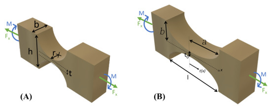
Figure 6.
Generalized model of the (A) circular hinge and (B) elliptical hinge(right) [50]. Key geometrical parameters for circular hinges are denoted as b, t and r for the thickness of circular hinges, web thickness and hinge radius respectively [50].
For CM-based FTS design, circular hinges are generally used more often than elliptical or bladed hinges as the former has the least parasitic motions due to its relatively thicker web. Parasitic errors can be characterized as undesirable movements made by the flexure components against their intended directions. The elliptical and bladed types tend to rotate out-of-plane when set in either parallel or serial layouts within the CM. A reduced parasitic error, without any out-of-plane rotation, is needed for ultraprecision machining. It is best parasitic errors are minimized as they tend to accumulate for example when flexure hinges are serially chained. Coupled motions in parallel CMs may contribute to parasitic errors as well.
2.2. Motion Decoupling
CMs suffer from coupled motions where actuator inputs specified for a particular direction structurally influence the CM to undesirably move in other directions. This is due to the cross-axis coupled deformation between flexure hinges and rigid components within the CM. Due to such movements, the CM’s output will experience parasitic errors that adversely affect the CM’s output positioning accuracy [52].
Parallel configured CMs have reportedly greater cross-axis coupling behavior. Not only that, single-input-single-output (SISO) control methodologies and sensor tracking during ultraprecision machining will be challenging with parallel configurations because of such issue [53]. Despite so, researchers have developed some workaround for motion decoupling parallel configured CMs. These are applicable for CM-based FTSs meant for any multiple DOF cutting actions. A basic but incomplete workaround for reducing cross-axis coupling includes aligning the stiffness center of the CM with its output center and introducing symmetry into the design. Alignment of CM’s stiffness center with output center is identical to having a collinear layout between the actuator, flexure hinges and diamond insert. Shang et al. designed a parallel flexure-based positioning stage that not only has a large output range of a millimeter and increased out-of-plane stiffness but also decoupled x and y motion [54]. Decoupling was achieved by Shang et al. with both a symmetrical design and 4 output support legs where each of them was a serially connected flexure hook joint. The flexure hook joint was able to successfully limit the cross-axis motions to within 0.65% and 0.82% in the x and y axes. X direction movements were simply decoupled from the y and θ directional by Bhagat et al. with flexure cantilevers [55]. Bhagat’s flexure cantilevered solution was able to have an x direction-coupled movement of only 1 µm with a y direction input of approximately 25 µm, and 0.2 µm y direction-coupled movement with an x direction input of 40 µm. Another workaround by Wang et al. use is to use a parallelogram flexure hinge parallel joined to a prismatic joint (shown in Figure 7), which was able to have lesser than 0.6% coupling ratio in both x and y directions [56]. However, a PID controller was used to enforce linearity and stability. Similar to actuator isolation using wire flexures, Chen et al. also combined parallelogram flexure modules with wire flexures for achieving motion decoupling for a 1DOF rotating stage [57]. With that workaround, the rotating stage had maximum coupling output angles less than 0.1 mrad and 0.16 mrad about the x and y axes.
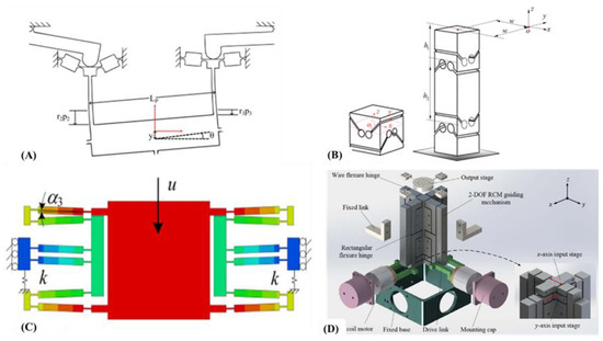
Figure 7.
(A) Coupled motion example where two topside hinges are actuated in an upwards direction and the center stage exhibits coupled rotation [55]; (B) Motion decoupling method with a hook joint flexure hinge and its linear-stacked leg version [54]; (C) A parallelogram hinge (blue) parallel connected with prismatic joint (green and orange) [56]; (D) A wire flexure hinge (at top) [57].
Motion decoupling can also be achieved by having CMs with serial designs. Though such designs are simpler to conceptualize in terms of kinematics modelling and control, they have increased mass which inevitably reduces first mode frequency. Therefore, serial CMs might not be suitable for high frequency machining as compared to parallel counterparts.
2.3. Amplification Structures
Due to the piezo actuator limitation, most CMs often suffer from limited output displacement [58]. Long stroke for FTSs is typically achieved by integrating displacement amplifying compliant structures into them. Figure 8 shows the 4 CM fundamental displacement amplifying structures, lever, Scott-Russell, buckling and bridge type. Another displacement amplifying structure includes the pantograph type [59].
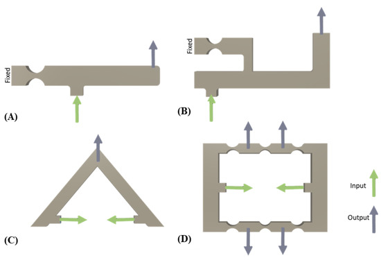
Figure 8.
Various types of displacement amplifying structures [40]. (A) Lever type; (B) Scott-Russell type; (C) Buckling type; (D) Bridge type.
The lever type is the most intuitive but with its asymmetrical layout, it is challenging to align its axis of actuation to the line of cutting action which leads to probably the greatest parasitic error [60]. A long lever length might provide greater mechanical leverage, but the structure will have poor stiffness. The Scott-Russell type overcomes the stiffness issue by simply adding an intermediate pivot point [61]. The misalignment between the actuation and the cutting axis is not solved though. Both amplifying structures output a curvilinear motion that must be taken into consideration when used for microfeature machining.
The buckling mechanism is a non-lever type structure with intrinsic symmetry and greater stiffness [62]. Its range of motion is somewhat limited compared to the lever types since its actuator is placed orthogonal to the line of cutting action. Due to its symmetrical flexing, the buckling mechanism has greater precision during machining. The bridge type is an enhancement of the buckling type where it now can drive two outputs with a single actuator [63]. Since each arm is subdivided into sections where each consists of a rigid structure and a bladed hinge, the bridge type structure may have greater parasitic error than the buckling type.
2.4. Actuators for CM-Based FTSs
Piezoelectric [64] and Lorentz force voice coil [65] actuators are mainly used to flex the CMs towards the workpiece during machining. Magnetism-based actuators include electromagnetic [66], magnetostrictive [67] and flux steered [68] types.
There are three fundamental configurations in which the actuator can be placed in the FTS w.r.t the cutting motion as shown in Figure 9 [69]. Cross-axis motions within the CMs can be expected to be greater for non-collinear layouts which could result in parasitic motions of the cutting tool during machining. Actuator heating up from prolonged or high frequency cutting can also cause the CM to deviate from its intended motion [70]. While commercially sold actuators can have very high 1st mode frequency above 10 kHz, machining at ultrasonic frequencies could still bring about a resonance-like effect that can pose challenges for closed loop positioning control. However, the resonance type machining can be highly useful for machining ferrous materials. Therefore, when designing CM-based FTSs for ultrahigh speed machining, structural stiffness needs to be modified as well for mitigating such effects.

Figure 9.
Common actuator, sensor (optional) and tool layouts for CM-based FTSs [69]. (A) Collinear layout; (B) Parallel-offset layout; (C) Non-parallel-offset layout.
2.4.1. Piezoelectric Actuator
Transducers which convert electrical energy into controlled mechanical motion via the piezoelectric effect are used as piezoelectric actuators in precision applications. Piezoelectric driven systems have better peak acceleration, bandwidth and minimized form factor compared to other types of actuators used in ultraprecision applications. However, they can only travel up to several hundred microns [71] and their cost is directly proportional to the stroke’s extent.
Common problems faced by piezoelectrically actuated FTSs include nonlinearity between input and output displacements, creep, thermal effects during high frequency operation, hysteresis and extension under load [72]. The proper selection of piezoelectric actuators is dependent on criteria such as required stroke, resistive loadings against actuation, static preloading on the actuator and actuator fall and rise time. The voltage applied to the actuator determines its actuation length and the time it requires to fully reach that actuation length is known as the slew rate. Equation (3) shows that the slew rate is primarily affected by the controller’s output current and the actuator’s capacitance. Smaller displacement actuators tend to have a lesser capacitance which allows them to extend a distance much faster than larger displacement counterparts.
The bandwidth of the actuator refers to the maximum operable frequency under the controller’s output current, applied voltage, actuator capacitance and driving signal. The bandwidth for the sine, triangle and square waves that are often used for driving FTSs are provided below and can also be retrieved from manufacturers such as Thorlabs, Inc.
There are a variety of piezoelectric actuators such as direct push, ultrasonic, inchworm and stick-slip types [73] and their strengths and weaknesses are summarized in Table 1. The direct push is the most frequently used for CM-based FTSs since its simple controls, high speed and large enough actuation force plunging the diamond insert into a workpiece is adequate for ultraprecision machining.

Table 1.
Comparisons of various piezoelectric actuator types.
Piezoelectric actuators manufactured by Physik Instrumente are very commonly used in research. Alternatives from COREMORROW Inc [56], NEC TOKIN Inc. [59] and Thorlabs have been used as well.
2.4.2. Electromagnetic Types
The electromagnetic actuators can be categorized under normal or shear stress. For the normal stress types, the tool behaves similarly to a maglev train, gliding along rapidly alternating electromagnetic poles. However, unlike the maglev train which operationally only moves forward, the normal stress EM type FTS is designed such that the tool goes back and forth with magnetic material flexural hinges being attracted and repelled periodically [66]. On the other hand, shear stress types such as the voice coil motor (VCM) [72], use permanent magnets and alternating current flow to get the tool reciprocally moving. A VCM driven FTS is shown in Figure 10 [78].
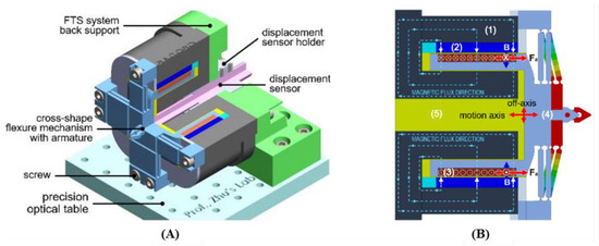
Figure 10.
Electromagnetically actuated CM-based FTS [78]. (A) CM components of FTSs are displayed; (B) Electromagnetic actuator components are shown where (1) stator, (2) permanent magnet, (3) coil, (4) moving stage and (5) air gap.
In terms of operating frequency, the normal stress EM type has the largest operating frequency band compared to the piezoelectric type [72], while the shear type VCM has a lower 1st mode frequency than the piezoelectric type. The normal stress type has greater accelerated output motion as compared to the shear type which makes it more suitable for machining difficult-to-machine metals.
The range of motion for the VCM is the highest compared to the normal stress EM and piezoelectric type. There is minimal need for displacement amplification structure for the VCM due to its inherent large stroke output capability [79]. Despite having a shorter range of motion compared to the VCM, the normal stress EM actuator can be used for very high frequency machining at 23 kHz [80]. One critical issue regarding VCM is that since its motion is from the weaker shear component of the magnetic flux, the FTS tends to have reduced bandwidth during high frequency machining that leads to inaccuracies in trajectory tracking [78].
Thermal performance wise, both the normal and shear stress EM and the piezoelectric actuators produce heat under prolonged operations. They all require advanced cooling systems not just for their electronics, but also for the CMs themselves to minimize machining inaccuracies attributed to thermal expansion. Even when a magnetic fluid which had five times greater thermal conductivity than air was used to dissipate heat away from a VCM’s air gap, the VCM was still able to reach temperatures higher than 80 °C after being used for more than an hour at a 2A current rating [81].
In terms of hysteresis, VCMs have zero to low hysteresis which implies a minimal need for linearity enforcing controllers such as the ones needed for the piezoelectric actuator.
Complex dynamic modelling involving electromagnetics is also needed if electromagnetic types are to be used.
2.4.3. VCM or Piezoelectric Actuator for Ultraprecision Machining?
Even though piezoelectric actuators are quite often used in CM-based FTSs, VCMs may also be utilized within a range of machining parameters that are less demanding on them. VCMs may have challenges in sustaining machining accuracy with an increase in either spindle rotation, feed or cutting depths. A higher spindle rotation will not only subject the CM to bending deformations but also require the actuator to work against higher torque loadings Increases in feed and depth of cuts will result in greater cutting resistance that may push back against the CM and the enclosed actuator if it has a reduced blocking force. With the VCM, it may also be challenging to process difficult-to-machine materials such as titanium and nickel composites in an environmentally sustainable manner since cutting them not only require a greater pushing force, a lot of heat gets generated [82] that will further complicate the VCM’s performance.
Despite the weakness of VCMs relative to piezoelectric actuators, precedents of them being successfully used for precision machining exists. An example by Tao et al. was able to accurately perform groove cutting and indent microstructures along a line [83]. Similarly, Chen et al. also used a VCM-FTS for machining a sinusoidal surface on a stationary workpiece [84]. It should be noted that Tao’s artificial intelligence-assisted VCM-FTS had a lower first mode frequency at 90 Hz compared to piezoelectric actuator types that are often preferred. Since their VCM-FTS performance evaluations were conducted on stationary workpieces with constant feed and depth of cuts, the question of whether VCM-FTS may be used for more challenging freeform surface machining may require further exploration. It should be noted that freeform surface machining involves varying workpiece rotations, feed, depth of cuts and difficult-to-machine materials.
The weaknesses of VCMs are offset by their budget friendliness and range of motion which far surpasses that of the piezoelectric actuator. Contemporary VCM models exist with submicrometer resolution and a range of motion at tens of millimeters.
The bottom line criteria for determining if a piezoelectric or VCM actuator is required for a FTS job include required surface roughness, workpiece material, the spatial frequency of surface features, machining duration and machining cost. For optical grade components, where surface roughness is to be no more than 100 nm, a high speed workpiece rotation, that inherently exert increased stresses on the FTS, is required. Using a piezoelectric actuator would be more practical due to its higher blocking force which is a few orders greater than what the VCM has. A higher blocking, push and pull force may also be useful for making deeper depths of cuts that are required for high aspect ratioed surface features. Cutting difficult-to-machine materials will also require the use of piezoelectric actuated FTSs since their exceptionally fast back-and-forth motion can easily shear away materials. If features are required to be sparsely machined on a large surface area, the VCM might be useful but if the opposite is required, then a piezoelectric actuator will be a better choice since it has better repeatability under high frequency operations. Prolonged machining, especially for large workpieces, leads to heat buildup which penalizes the VCM’s performance. If machining deeper depths of cuts at reduced feed and spindle rotation, the VCM may be more suitable for the job.
2.5. Manufacturing of CM-Based FTSs
While in general applications, high strength polymer material CMs are acceptable, metal material CMs are preferred for FTSs to be used for ultraprecision machining due to their toughness and prolonged fatigue life. Polymer CMs may not provide adequate stiffness against adverse machining forces arising from spindle rotation and hard metal workpieces, unlike their metal counterparts. While polymer structures are light and offer ease of handling, they might not last long when exposed to machining lubricants and surfactants.
The majority of FTSs with very thin flexural elements are manufactured with wire electrical discharge machining (WEDM). With WEDM, it is possible to fabricate CMs with hinges that are at micron scale at their thinnest section. Li et al.’s design had 1.1 mm radius circular hinges that were 800 µm thick at the thinnest portion [85]. Yang et al. fabricated a 500 µm thin blade hinge FTS [86]. Manufacturing the CM section of the FTS monolithically is a good practice, otherwise, the non-rigid fastening with screws of both components will lead to reduced positioning output [87]. It must be mentioned that manufacturing FTSs with WEDM, restricts design freedom to mostly planar form factors that ultimately limit the FTSs’ functionalities.
For overcoming restricted design freedom from using WEDM, additive manufacturing (AM) technology can be used. Though many variants of that technology exist ranging from fused deposition modelling to stereolithography, only a few can be said to be suitable for fabricating FTSs. AM using selective laser sintering, direct metal laser sintering and electron beam melting are those that can produce metal-based FTSs tough enough for ultraprecision machining.
FTSs are generally made of tough metal materials such as steel-based or high durability aluminum alloys, since they possess high fatigue strength and stress resistive materials which are needed for ensuring consistent machining performance. Metals with a low coefficient of thermal expansion should be preferred. Otherwise, even micrometer-scaled thermal expansion of the CM structure, which is unavoidable and arises from the actuator during prolonged cutting, can affect the surface finishing.
2.6. General Design Methodologies
CMs can be formally designed using the following general methodologies such as the building blocks technique [88], freedom and constraint topology (FACT) methodology [89], pseudo-rigid body modelling (PRBM) [90], kinematics-based methodologies [91] and topology optimization approaches [92]. In this section, each of these models will be further explored to provide a complete picture of the various design methodologies for CM.
2.6.1. Building Blocks Approach
The building blocks approach first identifies the directions along which the outputs of the CM are required to displace along. Following this, for each directional displacement, a flexure module is assigned. For example, in Figure 11A, a single DOF precision translational stage, a blade hinge is used as a fundamental block since it is known to be capable of 1DOF displacement. A right circular notch hinge could have been used for greater accuracy albeit with a reduced range of motion. Another bladed hinge is parallelly connected to the block’s stage for achieving symmetry-based parasitic error. In Figure 11B, for the same 1DOF moving stage, the previous block is now used in a different orientation. This time round, input displacements can be prescribed at two different locations compared to the block configuration used in Figure 11A. If the CM is required to move with greater DOFs, additional blocks are likewise assigned for those directions as in the case for a 2DOF stage by Awtar et al. [93].

Figure 11.
Example of a parallelogram flexure module used as a block for generating movement for each DOF [94]. (A) Single input-single output layout for a CM stage. (B) A multi-input-single output layout variant.
Alternatives to the parallelogram flexure block have been developed over recent years. One block has been designed as a double slider four bar mechanism which can convert a low frequency input to a higher frequency output [95]. Shell structures have also been studied and categorized based on their gaussian curvature and flexibility as blocks for CMs [96]. Lastly, an origami-based geometry which possesses bistability, helical output displacement and tunable structural stiffness has also been experimented with as a novel block [97]. CM-based FTSs generally use simple parallelogram flexure blocks nowadays, but with the use of these novel block designs, new design possibilities and functionalities could be realized.
2.6.2. Freedom and Constraint Topology
With the freedom and constraint topology (FACT) methodology, the designer is initially required to know the DOFs the CM is expected to have, and the planes along which it is required to be constrained. Just with these two considerations, multiple design variations for the CM can be visualized by referring to a highly systematic library developed by Hopkins and Culpepper [89]. In Figure 12, three different designs recommended by that library (1DOF Type 1) for a rotational 1DOF CM are shown. The planes, in blue, are known as constraint planes and they are where flexure hinges, or members, are usually placed to achieve the target output movement shown in red.
For Figure 12, bladed hinges were oriented along the recommended plane directions. Alternatively, circular, or elliptical hinges may be used for greater rotational precision though larger space might be needed to accommodate them. Hopkins and Culpepper have used wire-like struts as flexible members in many of their FACT-based designs [98]. Novel types of flexure hinges, not just CMs, can be designed conveniently with this methodology.
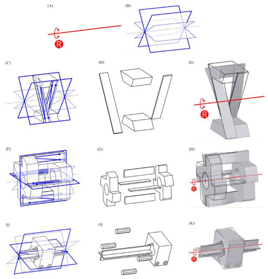
Figure 12.
FACT methodology was used to conceptualize several designs for a rotational 1DOF CM [98]. (A) The red arrow indicates the desired rotational movement for the CM, or its freedom. (B) The blue components indicates the planes, or constrains, along which flexure elements are to be oriented to achieve rotational motion. (C–E) Rotational CM with two blade hinges aligned perpendicular to rotational axis. (F–H) Another CM with four blade hinges aligned differently to produce the same rotational movement in (I). (I–K) The third design variation for the same rotational CM.
A CM-based 3DOF cutting tool has been developed by Lin et al. using this methodology [99]. The surface machined by their cutter had a surface roughness of 3.446 µm while another that was conventionally was higher at 9.912 µm. With the FACT methodology, Lin was able to identify the plane along which additional constraints are to be placed for raising positioning stability and thermal resistivity without much loss in machining accuracy. While Lin’s design’s lack of servo control discounts it from being a FTS, it can be considered a clear cut example of how the FACT can be useful for designing CM-based ultraprecision machining tools.
This methodology eschews mathematical formulations unlike the other methodologies listed in this section. Once the initial design of the CM is agreed upon with FACT, the mathematics-based approaches listed in this section can be used for optimization purposes.
2.6.3. Pseudo-Rigid Beam Modelling
Conventional modelling of beam deformations is only applicable where small deformations are assumed. When the flexure member is thin, it inevitably undergoes large deformations under loading which renders the conventional beam theory inapplicable for CMs. The PRBM method overcomes this problem by modelling identified flexible sections as torsional springs. For each flexible member, instead of using its original length, an approximate characteristic length is used instead as shown in Figure 13. The prefix, γ, of the characteristic length is known as the characteristic radius factor and it varies depending on the ratio between the horizontal and vertical component of applied force, n. While the characteristic length is useful for determining output positioning, the substitute torsional spring is prescribed a characteristic stiffness, K, for determining the output force of a flexible member. The characteristic stiffness is also dependent on n. The applicable γ and K values for different n are provided by Lusk [100]. Once the appropriate γ and K values are determined, and depending on how the loading is applied, algebraic equations relating the torque, x and y reaction forces, and angular and linear displacements are solved [90].
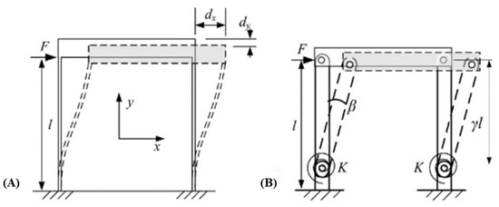
Figure 13.
(A)A parallel CM. (B) Its PRBM equivalent [101] with its l converted to its characteristic equivalent, γl and its flexing elements reinterpreted as torsional spring of characteristic stiffness K. Both γ and K are dependent on the loading subjected on them.
This method allows rapid and simple calculation of a flexure beam bending. Unlike the building blocks and FACT methodology, with the PRBM method, a quantitative mathematical model linking design parametric variations with output positioning and force can be established. Such models can be used for design optimizations towards accurate output positioning and force transmission.
The PRBM’s weaknesses include neglect of non-linear effects such as center shifting and load stiffening, applicability to only straight flexure beams, loss of accuracy for longer span beams and inability to model the beam’s tip angle when under loading. The modified PRBM (M-PRB) has been developed to address the various non-linear effects commonly attributed to CMs [102]. While the standard PRBM assigns pinned torsional spring to each flexible member, the M-PRBM assigns an additional axial spring. Compared with the original PRBM, its outputs were much closer to control finite element analysis (FEA) studies. To extend the PRBM to circular flexure beams, a generalized model had also been developed and found to have better accuracy than its predecessor [103]. While the PRBM uses only one torsional spring to model flexible bending, the generalized model uses at least two torsional springs for higher DOF bending.
For designing of FTSs, the PRBM method can be right after the flexure elements’ layouts are established with the building blocks or FACT methodology. Each block’s deformation can be rapidly calculated before subsequent finite element analysis studies.
2.6.4. Kinematics Approach
The kinematics approach assumes that the CM is a rigid body mechanism that undergoes small displacements, and then develops forward kinematics equations that relate the actuator’s input and orientation to the flexure hinges’ outputs [104]. An initial layout of the CM is still needed before using this method though. Therefore, FTS designers still need to rely on the building blocks or the FACT approach during the initial design stage.
Two kinematics approach includes the compliance matrix model (CMM) and the pseudo-static model (PSM). The compliance matrix model (CMM) involves developing stiffness matrices for each flexure element. Bernoulli’s theory can be used for developing stiffness matrices of simple beam flexures and Mohr’s integral method may be used for bent flexure members [105]. With the applied wrench, , consisting of forces and moments, together with the flexure member’s compliance matrix, C, the output twist, , consisting of the rotation and translation can be calculated [106]. The 6 × 6 C matrix’s coefficients depend on the flexure members’ shape and material and can be referred from [107].
Since a CM can have flexure elements serially or parallel arranged, the equivalent compliance matrix determination for both cases is computed differently. For the serial CM, the equivalent compliance for a complete serial CM is a summation of each flexure element’s compliance matrix transformed from its local coordinate frame as shown in Equation (7). Whereas for the parallel CM, the equivalent compliance matrix has more complexity as shown in Equation (8).
Wang et al. have noted that since each compliance matrix for a flexure element is intrinsically ill conditioned, inverting it for parallel CMs might lead to numerical instability. This translates to a significant disparity between estimated and calculated stiffness [108]. Despite remarking that the CMM might not produce ideal results for parallel CMs, Wang proved that if the CM has a relatively high rotational or radial translational compliance, the CMM can yield acceptable results. Most FTS designs mentioned in succeeding sections have used the CMM method to a great degree of accuracy.
Similar to the CMM method, the pseudo-static model (PSM) involves compliance matrices but one major difference is that dynamic properties are now included. Apart from being able to predict the output force and positioning, the PSM is also capable of computing the natural frequency of the CM design. Ling et al. have used the PSM method for their 2DOF CM design to accurately predict its natural frequency if one of its internal structure’s orientations varies [109].
2.6.5. Topology Optimization
Synthesis of CMs via topology optimization involves iteratively seeking the best structural layout in an approximate design domain by minimizing a target cost function without violating any prescribed constraints [110]. The most common constraints can be structural volume, and input and output displacements. Regions that are required to flex for achieving the desired output will be located as flexure points in the converged geometry [111]. These flexure points which are very small in form, pose manufacturing challenges and undoubtedly have heightened local stresses under loading [112]. Furthermore, using the numerically converged design as FTS will not be feasible during machining as high cutting forces could arise from the highly accelerated back-and-forth cutting motion into tough metal workpieces. Post processing steps such as flexure point enlargements are required to modify them into flexure hinges [113] before setting them up for use in SPDT. Identical to the aforementioned design methodologies, thermal effects are also not considered by solvers.
2.6.6. Data Driven Design Approach
As the designs of a CM become more complex, optimizing it with multi objectives becomes a very challenging matter, especially in terms of computational time. To address that, a new approach to CM design based on data has surfaced over recent years.
The toolset of this approach includes finite element analysis (FEA) software, statistics methods such as variance analysis (ANOVA), Taguchi methods, nature inspired optimization algorithms such as genetic algorithm, lightning attachment procedure optimization (LAPO), moth-flame optimization algorithm (MFO), cuckoo search algorithm and heuristics-based inference systems based on fuzzy logic, and adaptive neurofuzzy inference systems (ANFIS).
The workflow for the data driven design approach by Ngoc et al., which consists of five successive stages is shown in Figure 14 [114]. Sensitivity analysis during the design and simulation phase of Figure 14 is conducted using ANOVA to exclude the design parameters that have trivial influence over the design objective functions. Ngoc et al.’s approach then redefines the design with those parameters before pipelining them further into fuzzy inferences system followed by an ANFIS and MFO post processor. Ngoc et al. were able to successfully design a CM-based FTS with frequency and displacement greater than specified by the design objective by an agreeable margin. Dao et al. also designed a CM focus positioning platform with multiobjective optimization using a relatively simple workflow that has only two stages [115]. The first stage is similar to Ngoc’s while in the second stage, a different nature inspired optimization algorithm is used. Dao’s physics-based parameterized design objective functions are much more complex than Ngoc’s ones though.
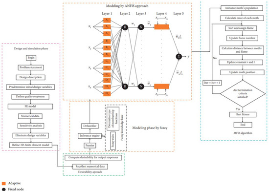
Figure 14.
Data driven design approach flowchart using ANFIS [114].
2.7. Actuator Isolation
During machining, the actuator will be subjected to potentially damaging shear loadings that could have come from the deflection of adjacent flexure members, especially when used for driving multiple axes FTSs or when connected in a non-collinear layout (see Figure 9B and 9C). The piezoelectric material is strong enough to handle axial compressive loadings but it is too brittle for lateral shear loadings [116].
Actuator isolation measures that borrow from decoupled CM designs can be integrated into the FTS. Zhou et al. developed a motion decoupled 2DOF tool using parallelogram flexure modules that were able to shunt lateral shear stress away from the actuator [117]. The FACT design methodology can be utilized to preliminarily identify where constraining flexures are to be set and oriented to direct shear loadings away from the actuator. The FACT methodology has allowed McCalib Jr and Hopkins to develop a variety of decoupling mechanisms for different types of loadings that could affect the actuator [118]. One such example is shown in Figure 15A. Alternatively, a simple wire beam can serve reasonably as a transverse loading decoupling mechanism at the cost of increased stiffness and cross-axis motions as shown in Figure 15B [119]. Though complete actuator isolation is impossible due to the CM’s inherent elasticity, Zhou et al. were able to isolate the actuator away from shear loadings by approximately 99% [117].
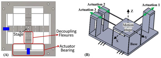
Figure 15.
Actuator isolation. (A)Isolation direction is firstly identified with FACT, and actuator decoupling flexures designed accordingly [118]; (B) Isolation with wire beams [119].
2.8. Types of CM-Based FTSs
The CM can be designed such that the FTS machines in either single or multiple DOF. The simplest single DOF FTS can have either a linear or rotational output whereas multiple DOF types can have a toolpath that is curvilinear [40]. Another way of grouping FTSs is with their stroke length where short stroke FTSs, intermediate stroke FTSs, and long stroke FTSs have displacement less than 100 microns, between 100 microns and 1 mm, and greater than 1 mm respectively [64].
In this section, selected examples of FTSs with notable CM designs are presented.
2.8.1. 1DOF FTS
The 1DOF FTS is a straightforward single actuator system with CM designs closely following those shown in Figure 16 [120]. Symmetrical designs can be easily thought of for the 1DOF FTS. Motion decoupling features are generally not considered for this configuration but it should be noted that any preloading of the piezoelectric actuator will result in minimized stroke output [121].
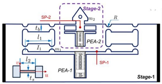
Figure 16.
One degree of freedom (1 DOF) dual staged, dual actuator type FTS [120].
The dual staged FTS is the solution developed by Zhao et al. to address low bandwidth issues encountered by 1DOF FTSs [120]. In this FTS, the lower stage’s actuator provides a longer stroke and lower frequency drive while the upper stage’s actuator provides otherwise. It has seen use in high-end applications such as scanning probe microscopy and feed drives of machine tools [122]. With operating frequencies of 100 Hz, 200 Hz and 300 Hz, the dual staged FTS was able to achieve errors of no more than . The disadvantage of this design is that it requires an additional actuator along with a sophisticated control algorithm to synchronize both of them.
2.8.2. Long Stroke FTSs
For manufacturing microstructures of higher aspect ratios or for achieving deeper cuts, FTSs capable of extended depth of cuts are often required.
Long stroke FTSs can be designed in a variety of interesting ways. The FTS developed by Wang and Yang, shown in Figure 17A is a straightforward design example of a lever amplified FTS [30]. Its simplified design allows an amplified output stroke of up to 540 µm from an input of approximately 180 µm. Dynamics performance-wise, due to its reduced form factor and resulting lower mass allows a higher first mode frequency of 2 kHz. A relatively more complex FTS which involves flexure levers and parallel springs were designed by Kim et al. that produced workpieces with a form accuracy error of no more than 150 nm [123]. For achieving such great precision, this design used symmetrically positioned parallel spring flexures for increasing stability during actuation and reducing parasitic error at the cutting output. The amplification ratio is greater at 5 compared to Wang and Yang’s FTS which is at 3 despite the symmetry enforced design.
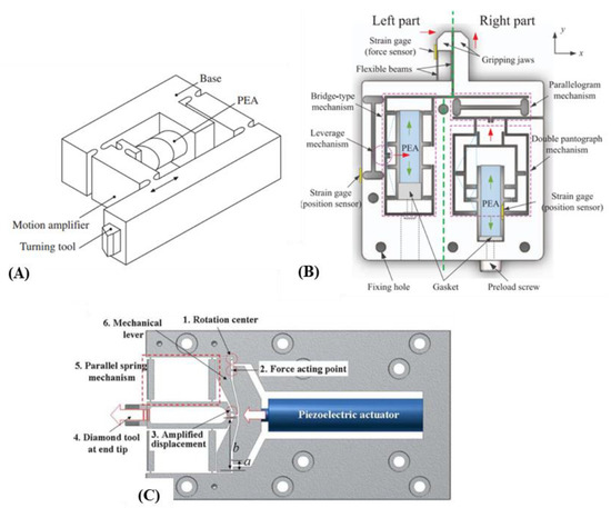
Figure 17.
Long stroke FTSs. (A) Simple long stroke CM-based FTS [30]; (B) Serially combined CM [59]; (C) Symmetric type [123].
The various amplifying structures in Figure 8 may also be serially combined within a CM for maximizing each other’s strengths. An innovative asymmetrical microgripper by Chen et al. was developed to have its left side primarily for lateral gripping and its right side constrained to allow only vertical movements that tighten the left side’s grip [59]. The serial connection of lever and bridge amplification structures can be seen on the left side of the microgripper whereas, on the right side, the pantograph amplification structure can be seen. Despite using identical actuators, the left hand side had roughly twice greater output displacement than the right side.
There exists a tradeoff between displacement amplification and first mode frequency for CMs [124]. The working bandwidth of a displacement amplifying FTS is generally reduced since cutting at both amplified displacements and high frequencies could result in positioning inaccuracies. The output force of the CM may also be reduced if serially stacked amplifying structures are used [57] since the presence of many flexure hinges can impair structural rigidity. This could make the FTS suitable for cutting only soft materials. Lever structures should be kept short otherwise a span too long will flex during the machining of harder metals. Voice coil motors may be used instead to achieve long stroke FTSs if a suitable CM design is not possible. Two instances of the same long stroke FTS could be symmetrically arranged to have one providing the cutting action and the other acting as a counterbalance. By doing so, Gong et al. were able to minimize the tracking error to lower than 1% [125]. However, the added mass might have reduced the system’s first mode frequency.
2.8.3. Multiple DOF FTS
Cross-axis couplings become worse for multi-DOF FTSs due to the presence of many interconnected flexure hinges. As the design becomes bulkier, the stiffness and resonance frequency may deteriorate. A CM-based FTS with novel z-shaped flexure hinges have been used by Zhu et al. for achieving ultraprecision machining of surfaces with finishing as low as Sa = 28.2 nm and Sa = 49.1 nm [126]. The z-shaped hinges allowed the FTS to have lower dynamic inertia at a much smaller form factor than what is possible in regular hinges. When compared with 1DOF machined workpieces, the workpieces by this FTS had lesser feed marks which consequently minimized undesirable light scattering fringes as shown in Figure 18B. A 3-PUU CM that grants 3DOF cutting for the FTS has been designed and experimentally verified by Tang et al., and it has a closed loop accuracy of no more than 600 nm [127]. For each branched chain of the 3-PUU structure, a bridge displacement amplifier had been used to maximize the FTS’ depth of cut to 120 µm.
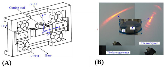
Figure 18.
Example of multiple DOF FTS. (A)FTS with z-shaped flexure hinges [126]. (B) On its right are 2 surfaces, Side labelled A is machined using the z-shaped flexure hinged FTS and B is machined with a conventional FTS. A has a lesser light scattering effect compared to B which therefore indicates the machining superiority of the multiple DOF FTS over the conventional one.
Liu et al. used dual bladed hinges, identical to the parallelogram flexure module, and a symmetrical layout for decoupling purposes for their 2DOF FTS [128]. Their CM was able to have coupled motions in both DOFs of no more than 1.4% and 2.22%. Wang et al. designed two pairs of filleted blade hinges for decoupling purposes which were arranged unconventionally in a non-orthogonal layout to have an acceptable coupling error within a maximum of 0.1331 µm [129].
Zhu et al. developed a 3DOF FTS which had a novel biaxial circular hinge that greatly aided in motion decoupling [130]. Their design had a high first mode frequency of 3.7 kHz. However, they noted that there were more noise-like inaccuracies observed for their FTS during machining when compared to during offline tracking and they attributed this to tool-workpiece interactions. Another 3DOF FTS with motion decoupling, resulting from the use of the dual axes notch flexure has been designed and verified in ultraprecision machining by Li et al. with an output stroke of up to 40 µm and coupling motions lesser than 2% [85]. The novel dual axes notched flexure that allowed x and y motion decoupling is shown in Figure 19A. They also remarked that the complex interactions between the machine tool and the cutting action could lead to inaccuracies in the machining. A hybrid serial-parallel triaxial FTS which is also capable of motion decoupling with the aid of eight quartered circular flexure beams has been developed by Zhu et al. [131]. Again, even though their FTS was verified to have a good ±1.29% tracking error at 3DOF, they noted the noise in the step responses of their FTS. Their design however is an advanced type which utilized both electromagnetic and piezoelectric actuators concurrently, A maximum tracking error of ±0.257 µm in the planar direction and ±64 nm in the vertical direction was observed for it.
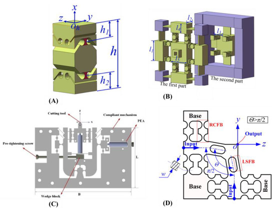
Figure 19.
Examples of CM-based FTSs with decoupled motions. (A) Dual-axis notched flexure [85]; (B) FTS with dual-axis notched flexures for both x (first part) and z (second part) direction decoupling [85]; (C) FTS with symmetrically laid out blade hinges [128]; (D) A non-orthogonal CM with blade hinges for motion decoupling [129].
2.8.4. Swing Output FTS
With the typical back-and-forth FTS motion, the fabrication of unique structures that, for example, are capable of preventing problems related to light interference phenomena might not be possible. A CM that converts linear piezoelectric input to a swinging rotational cutting output had been designed by Kim et al. [132]. Their horizontal swing FTS (hFTS) eschewed symmetry and the required additional overconstraining hinges to have a smooth output swinging motion. Interestingly, that caused no significant inaccuracy issues when the FTS was used to produce microstructures on a very hard Ni-coated steel roll mold.
2.8.5. Self-Sensing FTS
For real-time trajectory tracking of FTSs during SPDT, self-sensing FTSs have been developed. Apart from trajectory tracking, data related to tool wear and diamond tool edge chipping [133], real-time machining optimization and monitoring [134] are possible with this type of FTS.
Some design adjustments are required in the CM for ensuring high fidelity data logging without which the improper positioning of the sensors within the FTS could potentially impair dynamic performance and measurement accuracy. Mounting the sensors at the output end where the cutting insert is machining back-and-forth, generates extra mass and raised inertia which may weaken bandwidth, whereas mounting it at the opposite end behind the actuator might lead to measurement data that has cutting force coupled with the bending moments of the CM structure arising from actuator loading. CM structure might also bend when in contact with a rotating workpiece if it is not sturdy enough [135].
Several ideas for sensor placements have been explored and verified. Herrara-Granados et al. used an atomic force microscope inspired design where the sensor is placed on a flexible beam-like hinge and is in close contact with the cutting diamond tool which is on a parallel leaf spring cantilever as shown in Figure 20 [136]. While this design produced excellent machining results on glass workpieces, it requires cantilever stiffening before machining microstructures in harder materials. The beam structure might also have reduced first mode that prohibits high speed machining. Yang et al. developed a self-sensing FTS that has a novel feedback compliant unit that is placed at both the FTS’ front and back to minimize the measurement data coupling [86]. The positioning resolution was highly accurate at 22 nm and the measuring resolution of the thrust force was at 62 mN. A similar approach can also be seen with the design by Huang et al., where their FTS had a tracking error lesser than 3.66% and a higher natural frequency at 2260 Hz [137]. Their FTS was electromagnetically actuated which requires not just mathematical modelling with electromagnetic equations, but also some form of shielding against electromagnetic interference.
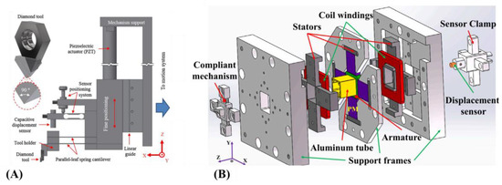
Figure 20.
(A) AFM inspired design [136]; (B) Dual compliant unit design [137].
Sensors are generally of capacitive types that can either measure force, displacement or even both [86]. For use in high speed machining, they must be capable of sampling at very high rates and for accurate measurements, they must ideally be of high resolution. Physik Instrumente, Micro-Epsilon, MicroSense and Lion Precision are manufacturers of such sensors.
The following Table 2 lists out the critical performance metrics for selected CM-based FTSs. For multiple DOF FTSs, the performance at each working axis is listed. The percentage value of the coupling error denotes the proportion of that axis’s movement that comes from cross-axis flexure deformations.

Table 2.
Selected CM FTS performance based on output stroke, static stiffness, first mode frequency, tracking and coupling error. ‘-’ indicates absence of data.
3. FTS Machining Performance Affecting Factors
During SPDT, the FTS’ machining accuracy is reportedly affected by many machining parameters such as spindle speed, workpiece material properties, tool overhang and tool wear. Improper selection of machining parameters can affect the interior CM’s performance by causing machining vibrations which may lead to undesirable surface finishing [138].
3.1. Machining Parameters
The main machining parameters that affect the FTS’ ultraprecision machining include feed rate, depth of cut, and spindle rotating speed. The increase in any of these parameters for the CNC machine generally raises both the stress loadings on the CM-based FTS and the tool wear rate of its cutting insert. An increase in feed rate may affect the accuracy of the microstructure’s width that is being machined [139] whereas an increase in the spindle rotating causes a greater bending moment for the FTS since its cutting insert is in dynamic contact with the spindle mounted rotating workpiece. When there is too much structural bending, the cutting force measurements made with a highly sensitive dynamometer will be undesirably coupled with the CM’s bending moments. In conventional diamond turning, a higher force reading generally arises from tool wear or great resistance due to increased feed, depth of cut or rotational speed. On the other hand, for diamond turning with CM-based FTSs, poor structural stiffness that comes from flexure hinges being too thin or tool material having a hardness value lower than the workpiece could result in higher force readings being registered. Furthermore, in the event the FTS undergoes catastrophic damage during very high speed machining, there is a high chance that its single crystal diamond gets irreversibly damaged since it is very brittle and vulnerable to thermal and sudden impact shocks.
A high feed or spindle rotation also leads to vibrations that can adversely affect the FTS’ machining performance. The feed rate must be controlled during microstructure machining on brittle workpieces so that crack-free finishing is possible [140]. Additionally, external sources of vibration that reach the FTS could also contribute likewise. This is especially so when the scale of the vibration amplitudes is approaching the scale of the features being machined. Examples of external vibration sources include reverberations from the ground being transmitted to a FTS’ machining base which has poor vibration isolation and workpiece-tool interaction that is known to lead to machining chatter. The consequences of not minimizing these vibrations include poor surface finishing and disturbances in closed loop controls which prevents the FTS from producing optical grade surfaces. An example of poor surface finishing due to machine chatter can be observed in Figure 21 [141].
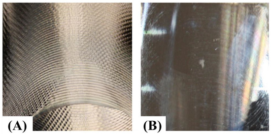
Figure 21.
Surface finishing [141]. (A) With chatter; (B) No chatter.
Other important parameters for microfeature machining are actuator driving frequency and amplitude. They are responsible for the depth accuracy of each machined microstructure [139].
Tool wear is also known to adversely affect the FTS’ diamond turning performance. Machining with a worn out or chipped diamond insert will require the FTS to experience a higher measured cutting force for material removal as compared to when using a sharper insert. Chipped tools will also leave behind burrs on the surface that will render them unsuitable for optical purposes. Reducing tool wear during machining is highly complex but having machining with a high feed rate and depth of cut tends to cause catastrophic tool wear [142].
3.2. CM Structural Stiffness
The structural stiffness of the CM-based FTS plays an important role during ultraprecision diamond turning where it must be sturdy enough to withstand actuation and cutting forces. A reasonable stiffness also brings about structural stability during high bandwidth machining without which trajectory tracking will challenging. Any closed loop controls implemented for the FTS will not work optimally due to the noises in positioning measurements. The FTS with poorer structural stiffness will undergo greater bending deformation when its cutting insert is in dynamic contact with the rotating workpiece.
For improving the structural stiffness of the CM-based FTS, the material choice, the type of flexure hinge being used, and their geometrical dimensions must be determined beforehand by using Equations (1) and (2) at least. Stiffness can also be generally improved by thickening the flexure hinges in the CM, but this sometimes leads to a reduced range of motion that limits the range of microstructures that can be machined.
3.3. Dynamic Characteristics
In some ultraprecision machining contexts, when CMs are operated at resonance, they tend to have higher amplitude vibrations that are constructive for surface texturing purposes. Unlike FTSs, they do not have deterministic positioning where the output motion can be algorithmically controlled to cut at a desired position at a particular time. In order to have determinism in its positioning, the FTS should ideally not undergo resonance since its output tool movements will become too unstable for tracking. It is also a good practice to design the CM to have a high first mode frequency so that external vibrations from the environment and machine chatter from workpiece-tool interactions have minimal effects on machining precision [143]. The first mode frequency of the FTS affects the bandwidth that it can conduct ultraprecision machining. For machining high density microstructures on a surface, the natural frequency of the FTS should be designed to be as high as possible.
The natural frequency of the FTS is greatly influenced by its material and design. Based on Equation (9), the natural frequency of common metal FTSs can be raised by adjusting their structural stiffness. It has been found that between a FTS with a stiffness of 403 N/µm [87] and another with 100.8 N/µm [144], the former had a 20 kHz natural frequency while the other had 6.61 kHz. Dynamics related performance can be further improved by eliminating CM symmetry since it reduces weight, however, this compromises the output accuracy of the FTS by introducing greater cross-axis coupling [145]. Section 2.1 discusses how CM structural stiffness can be raised during the initial design stage.
It has also been reported that the frequency at which the FTS operates has an adversarial effect on the FTS’ output displacement range. One FTS by Zhu et al. that had a natural frequency of 50.6 kHz, had a 75%, 50% and 20% reduction in positioning output when its piezoelectric driving frequency was raised to 2,5 and 10 kHz respectively [87]. Therefore, it is recommended to benchmark the FTS’ displacement range against applied frequency before any ultraprecision machining.
The positioning of the actuator within the FTS is another factor that affects its dynamic performance. One research found that when the actuator was placed near the output of the FTS, inertia was raised causing a drop in dynamic performance. Poor contact between the CM and the actuators contributed to such phenomena too. The dynamic performance drop caused a great disparity between FEA and actual measurement results. While FEA computed 1st mode and 2nd mode to be at 4038.2 Hz and 4939.6 Hz, the measured frequencies were only 863 Hz and 1893 Hz respectively instead [129].
3.4. Hysteresis
The hysteresis effect is generally exhibited by piezoelectric actuators and it is caused by the internal friction between its microcrystals that collectively move under an applied voltage [146]. Hysteresis should be mitigated as much as possible as it affects the output positioning and stability of the FTS. The hysteresis effect gets worse when the machining frequency of the FTS becomes higher with increasing non-linearity and decreased range of motion as shown in Figure 22A [147]. However, surface finishing for difficult-to-machine or brittle materials, such as glass, ceramics, germanium and silicon that are commonly used in advanced applications, is known to be better when machined at very high frequency [148]. While machining at lower frequencies, an increase in driving voltage tends to exacerbate hysteresis as shown in Figure 22B [147].
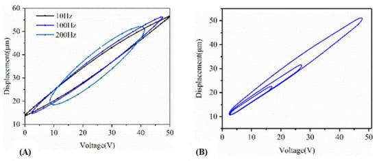
Figure 22.
Each hysteresis loop consists of both piezoelectric events, retraction and extension. For the same input voltage, the displacements for retraction are always greater than when extended. (A) Effect of frequency variation on hysteresis effect; (B) Hysteresis under sinusoidal loading of constant frequency, varying amplitude (right) [147].
Attempting to reduce the hysteresis with CM design is not advisable as it is an effect that stems intrinsically from the piezoelectric actuator. However, one structure related factor that could add to the hysteresis effect is CM overshoot. Tian et al. observed that, during extension and retraction of the piezoelectric actuator’s sphere tip, there will be a near instantaneous separation between itself and its contacting point on the FTS [116]. This separation which has some inertia to it always creates a large overshoot in the CM’s response to any piezoelectric actuation. The solution Tian and colleagues suggested was to increase the preload stiffness of the mounted piezoelectric actuator.
Closed loop control schemes are required to mitigate the non-linear hysteresis effect. Even though the CM structure is not the main contributor to the hysteresis effect, its stiffness and damping coefficients are often integrated as part of the closed loop control scheme [149]. It should be noted that with PID controls, there will be an unavoidable corresponding response rise time for each actuator step input, as high as 5.4 ms [117], which might have to be taken into consideration when programming the toolpath for high speed microstructure machining.
3.5. Fatigue
During protracted ultraprecision machining, flexure hinges in a CM-based FTS are cyclically loaded and that could cause fatigue wear at their thinnest region. To prolong their lifecycle, FTSs are often preemptively designed with tough materials and thick flexure hinges to ensure the minimum possibility of wear.
However, Yong et al. discovered that there is a limit to increasing the dimension of the flexure hinges beyond which there is no further improvement in fatigue reliability [150]. With the flexure hinge’s geometric parameters, mechanical properties and surface roughness known beforehand, designers can utilize the framework designed by Dirksen et al. to rapidly determine the fatigue life of their hinges [151]. This can avoid the problem of having very thick hinges that will reduce the FTS’ range of motion due to over stiffening.
It is also ideal that the surface roughness is kept as minimal as possible so that crack nucleation and propagation which leads to poor fatigue strength are avoided. Surface finishing of manufactured CMs can be improved with grinding.
3.6. Thermal
Actuator heat-up is an undesirable feature in CM-based FTSs. Another region where thermal buildup is unavoidable is where is workpiece’s surface material is being removed by the cutting insert. Anywhere else on the CM remains relatively cooler at ambient temperature thereby creating a temperature gradient. This phenomenon is known to cause thermal stresses on the CM that are capable of adversely affecting its output positioning accuracy [152]. Not only that, the non-linear behavior of the piezoelectric actuator will also be exacerbated, which requires cooling down before any further machining can be continued.
Manoach et al. discovered that when two CM were provided with the same input displacement, and when the temperature increased, one will experience greater stress than its room-temperature counterpart [153]. Though trivial for FTSs, this might translate to slightly higher than usual measured cutting force.
Hou et al. experimentally showed that when a compliant structure is stationary, it may start to vibrate when subjected to high temperature, whereas if it is already moving, even a small temperature change will induce considerable stress to it [70]. Considering this discovery, the CM-based FTS should be fabricated of a material that has low thermal conductivity such as steel, or high strength polymers. Since polymers lack structural stiffness, they tend to have a lower first mode frequency which limits their dynamic capability when used as FTSs.
In conventional turning, cooling fluids are used for bringing down the cutting temperature. This is very challenging with FTS-based diamond turning due to the placement of the actuator and sensor electronics. The practical solution proposed by researchers is to us CM symmetrical designs, though this comes with the risk of overconstraining [154].
4. Future Research
While the above-cited examples of CM-based FTSs are novel and of great utility to the ultraprecision manufacturing community, they still leave much room for innovation.
Firstly, data-driven design approaches have not been readily adopted. Data-driven approaches may be useful for generating knowledge bases for rapid prototyping in future. Current implementations of FTSs mainly use metal material for their structure which may be overengineered for making micrometer depth of cuts. Additively manufactured multi material FTSs of high grade polymers with innovative flexure hinge designs may be design optimized to realize the same functionalities which ultimately be more cost-effective. The FTSs also need to be developed further so that they can fabricate components with hierarchical surface structures. Currently, only texture generators such as elliptical vibration machines can produce such components but they lack deterministic positioning in the space and time domain. A conceptual merger of both concepts ought to be explored. Visualizing CM designs that can produce a desired cutting motion when actuated may be challenging to many. If a feature identification software, that can recognize a microstructure on a surface and produce the suitable CM that can machine such microstructure, exists, design time can be reduced. Conventional machining such as turning and milling has advanced CAD/CAM integration capabilities. Such capabilities need to be developed so for FTSs as well.
4.1. Towards Data-Driven Design Approach
In the current era of Industry 4.0, data-driven approaches are favored in many engineering scenarios. It is time they are adopted at a larger scale in the design of CM-based FTSs. In Section 2.6.6, the data-driven design framework by Ngoc et al. showed great promise in developing a highly optimized CM design for an FTS. Ngoc has also further proven the feasibility of his approach by designing a different type of CM with the same framework but a different nature inspired optimization algorithm at the final stage [155]. Amine et al. designed an interactive software tool that uses complex backend optimization algorithms for the synthesis of CMs [156]. Currently, this data-driven approach is only found to be suitable for developing simple CM designs. Applying them for highly complex multiple DOF designs is very challenging due to increased FEA computation time during training dataset generation. Therefore, an urgent need for a highly efficient framework, which includes algorithms that have reduced time complexity, and that can design multiple DOF FTSs with challenging form factors exists at the moment.
4.2. Machining of Hierarchical Structured Surfaces with CM-Based Tools
Current implementations of FTSs are only able to fabricate single-level microstructures such as the ones shown in Figure 3. While such microstructures allow the surface to have exceptional optical-related properties, they do not grant enhanced mechanical or material properties. Hierarchical surfaces, such as the one shown in Figure 23B, allow a surface to have biomimetic capabilities such as hydrophobicity, oleophobicity and self-cleaning. He et al. have also demonstrated that machined hierarchical structures on a surface can be used for structural coloration purposes, such as invisibility cloaking and microdisplays [157]. Achieving them with contemporary FTSs is currently a great challenge as they lack the bandwidth and control systems for machining the higher spatial frequency microstructures.
Despite this, Dennis et al. were able to produce hierarchical surfaces with the FTS by combining it with a slow slide servo for the lower-frequency macrostructures [158]. However, this method can only produce lower-density micro-featured surfaces within a 5 mm-by-5 mm circular workspace. Currently, hierarchical surfaces are preferably fabricated using laser etching or chemical deposition methods which might be costly for mass production [159].
For addressing the abovementioned issues, researchers have been developing vibration-assisted texture generators that are heavily inspired by existing FTSs. The main difference between these texture generators and FTSs is that since the former lacks the servo aspect, its operation is not positionally deterministic at any specific time. Yuan et al. developed one 2DOF CM-based texture generator that can produce not just higher frequency microstructures on a lower frequency sinusoidal surface, but also on a discontinuous cubic surface [160]. Likewise, Guo et al. also developed their texture generator that has a dual-flexure hinged block actuated by two ultrasonic Langevin transducers [161]. Unlike Yuan’s design, Guo’s is meant to work at the resonant frequency for a greater depth of cut. When the transducers are oscillating at the natural frequency of the FTS, the angled orientation of the flexure hinges deforms accordingly to produce a unique textured surface shown in Figure 23D. One noticeable feature regarding the two cited examples is that they both use dual actuators for achieving the textured surfaces. To achieve resonant cutting, adjustable end masses can be placed on the cutter and adjusted to achieve the required first mode frequency similarly to how Guo did.
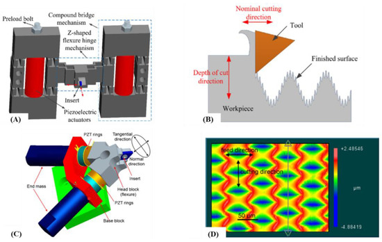
Figure 23.
CM-based ultraprecision texturing tools. (A) 2D vibration assisted cutter and its (B) machined hierarchical surface. As the tool cuts out the larger sinusoidal freeform surface at a slower frequency with one piezoelectric actuator, the other actuator drives the cutting insert at a higher frequency but smaller depth of cut to produce the micro/nano microstructures on the sinusoidal surface [160]; (C) 2DOF elliptical vibration texturing tool and its (D) dimpled microtextured surface [161].
Taking the above as inspiration, current research ought to develop newer types of CMs for producing higher frequency microstructures. With different CM designs, distinctive types of textured surfaces not possible with the traditional FTSs may be produced.
4.3. Multimaterial FTSs
A CM need not be constrained to be made of a single material. Unrelated to machining, a simple clip and a complex rotor system with functionally graded Young’s modulus have been investigated as multi material CMs [162]. The studies showed that the multi material approach permitted more complex designs and significantly reduced assembly part count and duration. Another study which developed compliant multi material micro aerial vehicles reported having the same benefits [163]. While current FTSs have complex CM designs, a multi materials approach to them has yet to be ventured into. Additionally, current additive manufacturing technology is capable of multi material printing, and it is time CM-based FTSs make use of this technology for realizing previously unknown functionalities.
4.4. Integration of Innovative Flexure Hinges
The notch hinge is very commonly used in CM-based FTSs along with the bladed hinge. It has good rotational precision but a very limited range of motion while the bladed hinge deflection is imprecise with a greater range of motion [164]. For addressing this issue, researchers have experimented with different flexible structures as hinges such as the elliptical type [165], micropillar type [166], multicavity flexure hinge [167], triply periodic minimal surface latticed flexure hinge [168], cross-axis hinge [169] and cartwheel hinge [170]. Some of these hinges can be integrated into FTSs for improved machining accuracy and performance. For example, the lighter TPMS latticed flexure hinge [168] is known to have the same stiffness as its filled counterpart and by utilizing the lighter option, the CM-based FTS could theoretically have higher first mode frequency according to Equation (9). Recent advances in additive manufacturing can help fabricate those novel hinged FTSs since it is impossible to do so with WEDM.
4.5. CM Design Based on Automated Feature Identification
It is a known fact that different microstructures can grant unique mechanical and material properties to a surface. At the moment, FTSs such as those mentioned in Section 2.8 are developed mostly through trials and errors and then experimentally verified to produce a distinct microfeature. It would be ideal if a feature is first identified algorithmically, for example, a hydrophobic microstructure of a lotus leaf from a photograph, and then with the use of automated decision making models, the appropriate CM which flexes to cut along the profile of the microfeature can be automatically. Such tools can shrink the duration of the design stage significantly.
4.6. CAD/CAM Integration
Currently, commercial CAD/CAM programs are only able to produce machining toolpaths for conventional CNC machines. For producing toolpaths for FTSs, researchers have to first develop their algorithms based on complex mathematics dependent on multiple machining parameters such as cutting tool geometry, machining feed, depth of cut and many more [171]. During ultraprecision machining, the FTS itself has flexure hinges deforming dynamically to affect the depth of cut and that has to be taken into consideration when developing the toolpaths. Innovative algorithms that attempt to solve this lack of CAM integration have been devised so far [158]. The task however becomes more challenging when FTSs begin to have output motion capability at 2DOF and beyond.
5. Conclusions
Till now, review papers on FTSs provided limited insights on how CM structure affects their ultraprecision machining performance. There was no single material which listed out the various design methodologies and considerations such as actuator selection and isolation, motion decoupling, design and fabrication methodologies and techniques. In this paper, a comprehensive review of all these matters was provided as a guide for researchers in ultraprecision machining. This paper also elaborated on factors that have been overlooked by prior review papers which may play a significant role in ultraprecision machining performance. The factors include machining parameters such as feed and depth of cut, CM stiffness, dynamic performance, hysteresis, fatigue and thermal effects. A comprehensive list of the various configurations of CM-based FTSs developed by leading researchers had also been provided as a reference for future design efforts. It is hoped that with this review paper, the design of CM-based FTSs reaches new heights, and with the resultant novel functionalities, be of even greater utility for the manufacturing community.
Author Contributions
Conceptualization, S.K.A., N.Y.J.T. and V.P.; methodology, S.K.A., N.Y.J.T. and V.P.; writing—original draft preparation, N.Y.J.T., V.P.; writing—review and editing, S.K.A., N.Y.J.T. and V.P; supervision, S.K.A., N.Y.J.T.; project administration, S.K.A.; funding acquisition, S.K.A. All authors have read and agreed to the published version of the manuscript.
Funding
This research is supported by the Ministry of Education, Singapore, under its Academic Research Fund Tier 1 (R-265-000-690-114).
Data Availability Statement
No new data were created.
Conflicts of Interest
The authors declare no conflict of interest.
References
- Boni, C.; Royer-Carfagni, G. A New Flexural-Tensegrity Bow. Mech. Mach. Theory 2021, 164, 104398. [Google Scholar] [CrossRef]
- Howell, L.L.; Magleby, S.P.; Olsen, B.M. Handbook of Compliant Mechanisms; John Wiley & Sons: Hoboken, NJ, USA, 2013. [Google Scholar] [CrossRef]
- Marathe, P.; Pardeshi, S.S.; Deshmukh, B. Development of Bridge and Lever Type Compact Compliant Mechanism for Micro Positioning Systems. J. Phys. Conf. Ser. 2021, 1969, 12006. [Google Scholar] [CrossRef]
- Kirmse, S.; Campanile, L.F.; Hasse, A. Synthesis of Compliant Mechanisms with Selective Compliance-An Advanced Procedure. Mech. Mach. Theory 2021, 157, 104184. [Google Scholar] [CrossRef]
- Liang, Y.; Sun, K.; Cheng, G. Discrete Variable Topology Optimization for Compliant Mechanism Design via Sequential Approximate Integer Programming with Trust Region (SAIP-TR). Struct. Multidiscip. Optim. 2020, 62, 2851–2879. [Google Scholar] [CrossRef]
- Olesnavage, K.M.; Johnson, W.B.; Professor, M.J.M.; Winter, A.G. Design and Testing of a Prosthetic Foot with Interchangeable Custom Springs for Evaluating Lower Leg Trajectory Error, an Optimization Metric for Prosthetic Feet. J. Mech. Robot. 2018, 10, 021010. [Google Scholar] [CrossRef]
- Miao, Y.; Zheng, J. Optimization Design of Compliant Constant-Force Mechanism for Apple Picking Actuator. Comput. Electron. Agric. 2020, 170, 105232. [Google Scholar] [CrossRef]
- Zhang, Y.; Ge, W.; Zhang, Z.; Mo, X.; Zhang, Y. Design of Compliant Mechanism-Based Variable Camber Morphing Wing with Nonlinear Large Deformation. Int. J. Adv. Robot. Syst. 2019, 16, 1–19. [Google Scholar] [CrossRef]
- Ahuett-Garza, H.; Melecio, J.I.; Orta, P. Modal Analysis of a New Thermosensitive Actuator Design for Circuit Breakers Based on Mesoscale U-Shaped Compliant Mechanisms. Math. Probl. Eng. 2018, 2018, 2850309. [Google Scholar] [CrossRef]
- Hansen, B.J.; Carron, C.J.; Jensen, B.D.; Hawkins, A.R.; Schultz, S.M. Plastic Latching Accelerometer Based on Bistable Compliant Mechanisms. Smart Mater. Struct. 2007, 16, 1967–1972. [Google Scholar] [CrossRef]
- Wang, W.; Li, C.; Rodrigue, H.; Yuan, F.; Han, M.W.; Cho, M.; Ahn, S.H. Kirigami/Origami-Based Soft Deployable Reflector for Optical Beam Steering. Adv. Funct. Mater. 2017, 27, 1604214. [Google Scholar] [CrossRef]
- Cui, Z.; Jiang, H. Design, Analysis, and Simulation of a Planar Serial-Parallel Mechanism for a Compliant Robotic Fish with Variable Stiffness. Res. Artic. Adv. Mech. Eng. 2016, 8, 1–13. [Google Scholar] [CrossRef]
- Liu, T.; Hao, G. Design of Deployable Structures by Using Bistable Compliant Mechanisms. Micromachines 2022, 13, 651. [Google Scholar] [CrossRef] [PubMed]
- Li, S.; Hao, G. Design and Nonlinear Spatial Analysis of Compliant Anti-Buckling Universal Joints. Int. J. Mech. Sci. 2022, 219, 107111. [Google Scholar] [CrossRef]
- Li, Y.; Zhu, X.; Bi, S.; Guo, R.; Sun, J.; Hu, W. Design and Development of Compliant Mechanisms for Electromagnetic Force Balance Sensor. Precis. Eng. 2020, 64, 157–164. [Google Scholar] [CrossRef]
- Wiese, M.S.; Dratsch, T.; Plum, P.S.; Lorenz, F.; Rieck, I.; Pinto Dos Santos, D.; Alakus, H.; Bludau, M.; Kleinert, R.; Goeser, T.; et al. Palliation of Malignant Dysphagia with a Segmented Self-Expanding Metal Stent: A STROBE-Compliant Article. Medicine 2021, 100, e27052. [Google Scholar] [CrossRef]
- Taniguchi, N. Current Status in, and Future Trends of, Ultraprecision Machining and Ultrafine Materials Processing. CIRP Ann. 1983, 32, 573–582. [Google Scholar] [CrossRef]
- Khaghani, A.; Cheng, K. Investigation on an Innovative Approach for Clamping Contact Lens Mould Inserts in Ultraprecision Machining Using an Adaptive Precision Chuck and Its Application Perspectives. Int. J. Adv. Manuf. Technol. 2020, 111, 839–850. [Google Scholar] [CrossRef]
- Chen, S.; Xue, S.; Zhai, D.; Tie, G. Measurement of Freeform Optical Surfaces: Trade-Off between Accuracy and Dynamic Range. Laser Photon. Rev. 2020, 14, 1900365. [Google Scholar] [CrossRef]
- Yang, T.; Jin, G.F.; Zhu, J. Automated Design of Freeform Imaging Systems. Light Sci. Appl. 2017, 6, e17081. [Google Scholar] [CrossRef]
- Brinksmeier, E.; Gläbe, R.; Schönemann, L. Diamond Micro Chiseling of Large-Scale Retroreflective Arrays. Precis. Eng. 2012, 36, 650–657. [Google Scholar] [CrossRef]
- Huang, R.; Zhang, X.; Neo, W.K.; Kumar, A.S.; Liu, K. Ultra-Precision Machining of Grayscale Pixelated Micro Images on Metal Surface. Precis. Eng. 2018, 52, 211–220. [Google Scholar] [CrossRef]
- Zhang, X.; Huang, R.; Liu, K.; Kumar, A.S.; Shan, X. Rotating-Tool Diamond Turning of Fresnel Lenses on a Roller Mold for Manufacturing of Functional Optical Film. Precis. Eng. 2018, 51, 445–457. [Google Scholar] [CrossRef]
- Neo, D.W.K.; Kumar, A.S.; Rahman, M. An Automated Guilloche Machining Technique for the Fabrication of Polygonal Fresnel Lens Array. Precis. Eng. 2015, 41, 55–62. [Google Scholar] [CrossRef]
- Jin, N.T.Y.; Jin, N.T.Y.; Lim, Z.H.; Zhou, G.; Liu, K.; Kumar, A.S. Design and Fabrication of Composite Polygonal Fresnel Lenses. Opt. Express 2021, 29, 36516–36534. [Google Scholar] [CrossRef]
- Wu, B.; Zong, W. A Modified Diamond Micro Chiseling Method for Machining Large Scale Retroreflective Microstructure on Nickel Phosphorus Alloy. J. Mater. Process. Technol. 2022, 307, 117676. [Google Scholar] [CrossRef]
- Zhang, X.Q.; Huang, R.; Kumar, A.S.; Liu, K. High-Efficiency Swinging-Rotating Diamond Shaping of Fresnel Lenses on Roller Molds. CIRP Ann. 2018, 67, 121–124. [Google Scholar] [CrossRef]
- Chen, Z.Z.; Chen, J.N.; Zhang, X.Q.; Zhu, L.M. Fabrication of Polygonal Fresnel Lenses with a Rotating Cutting Tool on Three-Axis Ultraprecision Lathes. Precis. Eng. 2022, 76, 385–396. [Google Scholar] [CrossRef]
- Zhou, H.X.; Tan, K.K. Speed Non-Circular Piston Turning Using Extracted Computer Numerical Control (CNC) Approach High. In Proceedings of the 2004 IEEE Region 10 Conference TENCON, Chiang Mai, Thailand, 24–24 November 2004. [Google Scholar] [CrossRef]
- Wang, H.; Yang, S. Design and Control of a Fast Tool Servo Used in Noncircular Piston Turning Process. Mech. Syst. Signal Process. 2011, 36, 87–94. [Google Scholar] [CrossRef]
- Boinski, A.K.; Riemer, O.; Karpuschewski, B.; Schneider, M.; Guttmann, M.; Worgull, M. Fast Tool Machining and Hot Embossing for the Manufacture of Diffractive Structured Surfaces. Precis. Eng. 2022, 74, 12–19. [Google Scholar] [CrossRef]
- Chen, Y.-L.; Wang, S.; Shimizu, Y.; Ito, S.; Gao, W.; Ju, B.-F. An In-Process Measurement Method for Repair of Defective Microstructures by Using a Fast Tool Servo with a Force Sensor. Precis. Eng. 2015, 39, 134–142. [Google Scholar] [CrossRef]
- Ju, B.F.; Zhu, W.L.; Yang, S.; Yang, K. Scanning Tunneling Microscopy-Based in Situ Measurement of Fast Tool Servo-Assisted Diamond Turning Micro-Structures. Meas. Sci. Technol. 2014, 25, 55004. [Google Scholar] [CrossRef]
- Ping, D.; Gan, S.W.; Wong, Y.S.; Hong, G.S.; Mustafizur, R.; Yao, J. Optimized Tool Path Generation for Fast Tool Servo Diamond Turning of Micro-Structured Surfaces. Int. J. Adv. Manuf. Technol. 2012, 63, 1137–1152. [Google Scholar] [CrossRef]
- Zhang, H.; Dong, G.; Zhou, M.; Song, C.; Huang, Y.; Du, K. A New Variable Structure Sliding Mode Control Strategy for FTS in Diamond-Cutting Microstructured Surfaces. Int. J. Adv. Manuf. Technol. 2012, 65, 1177–1184. [Google Scholar] [CrossRef]
- Ludwick, S.J.; Chargin, D.A.; Calzaretta, J.A.; Trumper, D.L. Design of a Rotary Fast Tool Servo for Ophthalmic Lens Fabrication. Precis. Eng. 1999, 23, 253–259. [Google Scholar] [CrossRef]
- Li, D.; Wang, B.O.; Qiao, Z.; Jiang, X. Ultraprecision Machining of Microlens Arrays with Integrated On-Machine Surface Metrology. Opt. Express 2019, 27, 212–224. [Google Scholar] [CrossRef]
- Keeratihattayakorn, S.; Tangpornprasert, P.; Prasongcharoen, W.; Virulsri, C. Out-of-Roundness Compensation Technique in Machining of Femoral Head Prosthesis Using Conventional CNC Machine. Int. J. Adv. Manuf. Technol. 2020, 107, 2537–2545. [Google Scholar] [CrossRef]
- Wee, D.; Neo, K.; Kumar, A.S.; Rahman, M. A Novel Surface Analytical Model for Cutting Linearization Error in Fast Tool/Slow Slide Servo Diamond Turning. Precis. Eng. 2014, 38, 849–860. [Google Scholar] [CrossRef]
- Zhu, L.; Li, Z.; Fang, F.; Huang, S.; Zhang, X. Review on Fast Tool Servo Machining of Optical Freeform Surfaces. Int. J. Adv. Manuf. Technol. 2018, 95, 2071–2092. [Google Scholar] [CrossRef]
- Gong, Z.; Huo, D.; Niu, Z.; Chen, W.; Cheng, K. Robustness Evaluation of Control Algorithms for a Long-Stroke Fast Tool Servo. J. Manuf. Process. 2022, 80, 458–468. [Google Scholar] [CrossRef]
- Brinksmeier, E.; Karpuschewski, B.; Yan, J.; Schönemann, L. Manufacturing of Multiscale Structured Surfaces. CIRP Ann. 2020, 69, 717–739. [Google Scholar] [CrossRef]
- Brinksmeier, E.; Glä, R.; Schö, L. Review on Diamond-Machining Processes for the Generation of Functional Surface Structures. CIRP J. Manuf. Sci. Technol. 2012, 5, 1–7. [Google Scholar] [CrossRef]
- Zhang, S.; Zhou, Y.; Zhang, H.; Xiong, Z.; To, S. Advances in Ultra-Precision Machining of Micro-Structured Functional Surfaces and Their Typical Applications. Int. J. Mach. Tools Manuf. 2019, 142, 16–41. [Google Scholar] [CrossRef]
- Brigham Young University, Compliant Mechanisms Research. About Compliant Mechanisms|Compliant Mechanisms. Available online: https://www.compliantmechanisms.byu.edu/about-compliant-mechanisms (accessed on 21 March 2023).
- Tian, Y.; Shirinzadeh, B.; Zhang, D.; Zhong, Y. Three Flexure Hinges for Compliant Mechanism Designs Based on Dimensionless Graph Analysis. Precis. Eng. 2010, 34, 92–100. [Google Scholar] [CrossRef]
- Dong, W.; Sun, L.; Du, Z. Stiffness Research on a High-Precision, Large-Workspace Parallel Mechanism with Compliant Joints. Precis. Eng. 2008, 32, 222–231. [Google Scholar] [CrossRef]
- Wang, L.-P.; Jiang, Y.; Li, T.-M. Analytical Compliance Modeling of Serial Flexure-Based Compliant Mechanism Under Arbitrary Applied Load. Chin. J. Mech. Eng. 2017, 30, 951–962. [Google Scholar] [CrossRef]
- Panas, R.M. Large Displacement Behavior of Double Parallelogram Flexure Mechanisms with Underconstraint Eliminators. Precis. Eng. 2016, 46, 399–408. [Google Scholar] [CrossRef]
- Aravind Raghavendra, M.R.; Senthil Kumar, A.; Nikhil Jagdish, B. Design and Analysis of Flexure-Hinge Parameter in Microgripper. Int. J. Adv. Manuf. Technol. 2010, 49, 1185–1193. [Google Scholar] [CrossRef]
- Smith, S.T. Flexures: Elements of Elastic Mechanisms. In Flexures; CRC Press: London, UK, 2000. [Google Scholar] [CrossRef]
- Shao, J.Y.; Ding, Y.C.; Liu, H.Z.; Li, X.M.; Tian, H.M.; Xiao, B.H. Monolithic Design of a Compliant Template Orientation Stage for Step Imprint Lithography. Proc. Inst. Mech. Eng. Part B J. Eng. Manuf. 2011, 226, 221–228. [Google Scholar] [CrossRef]
- Li, Y.; Xu, Q. A Totally Decoupled Piezo-Driven XYZ Flexure Parallel Micropositioning Stage for Micro/Nanomanipulation. IEEE Trans. Autom. Sci. Eng. 2011, 8, 265–279. [Google Scholar] [CrossRef]
- Shang, J.; Tian, Y.; Li, Z. A Novel Voice Coil Motor-Driven Compliant Micropositioning Stage Based on Flexure Mechanism. Rev. Sci. Instrum. 2015, 86, 95001. [Google Scholar] [CrossRef]
- Bhagat, U.; Shirinzadeh, B.; Clark, L.; Chea, P.; Qin, Y.; Tian, Y.; Zhang, D. Design and Analysis of a Novel Flexure-Based 3-DOF Mechanism. Mech. Mach. Theory 2013, 74, 173–187. [Google Scholar] [CrossRef]
- Wang, F.; Zhao, X.; Huo, Z.; Shi, B.; Liang, C.; Tian, Y.; Zhang, D. A 2-DOF Nano-Positioning Scanner with Novel Compound Decoupling-Guiding Mechanism. Mech. Mach. Theory 2021, 155, 104066. [Google Scholar] [CrossRef]
- Chen, W.; Chen, S.; Qu, J.; Chen, W. A Large-Range Compliant Remote Center of Motion Stage with Input/Output Decoupling. Precis. Eng. 2017, 51, 468–480. [Google Scholar] [CrossRef]
- Xu, Q.; Li, Y. Analytical Modeling, Optimization and Testing of a Compound Bridge-Type Compliant Displacement Amplifier. Mech. Mach. Theory 2011, 46, 183–200. [Google Scholar] [CrossRef]
- Chen, W.; Qu, J.; Chen, W.; Zhang, J. A Compliant Dual-Axis Gripper with Integrated Position and Force Sensing. Mechatronics 2017, 47, 105–115. [Google Scholar] [CrossRef]
- Li, Y.; Ge, W.; Zhang, X.; Tong, X. Optimization and Experiment of a Novel Compliant Focusing Mechanism for Space Remote Sensor. Sensors 2020, 20, 6826. [Google Scholar] [CrossRef]
- Ai, W.; Xu, Q. New Structural Design of a Compliant Gripper Based on the Scott-Russell Mechanism Regular Paper. Int. J. Adv. Robot. Syst. 2014, 11, 192. [Google Scholar] [CrossRef]
- Jiang, J.; Mockensturm, E. A Motion Amplifier Using an Axially Driven Buckling Beam: I. Design and Experiments. Nonlinear Dyn. 2006, 43, 391–409. [Google Scholar] [CrossRef]
- Dong, W.; Chen, F.; Gao, F.; Yang, M.; Sun, L.; Du, Z.; Tang, J.; Zhang, D. Development and Analysis of a Bridge-Lever-Type Displacement Amplifier Based on Hybrid Flexure Hinges. Precis. Eng. 2018, 54, 171–181. [Google Scholar] [CrossRef]
- Sosnicki, O.; Pages, A.; Pacheco, C.; Maillard, T. Servo Piezo Tool SPT400MML for the Fast and Precise Machining of Free Forms. Int. J. Adv. Manuf. Technol. 2009, 47, 903–910. [Google Scholar] [CrossRef]
- Liu, H.; Sun, Y.; Zhu, B.; Hu, Y.; Xie, W. Inertial Force Control and Balance Error Analysis of Fast Tool Servo Based on the Voice Coil Motor. In Proceedings of the 2014 20th International Conference on Automation and Computing, Cranfield, UK, 12–13 September 2014; pp. 243–247. [Google Scholar] [CrossRef]
- Gutierrez, H.M.; Ro, P.I. Sliding-Mode Control of a Nonlinear-Input System: Application to a Magnetically Levitated Fast-Tool Servo. IEEE Trans. Ind. Electron. 1998, 45, 921–927. [Google Scholar] [CrossRef]
- Liu, D.; Sutherland, J.W.; Moon, K.S.; Stums, T.J.; Kashani, A.R. Surface Texture Improvement in the Turning Process Via Application of a Magnetostrictively Actuated Tool Holder. J. Dyn. Syst. Meas. Control. 1998, 120, 193–199. [Google Scholar] [CrossRef]
- Trumper, D.L.; Lu, X. Fast Tool Servos: Advances in Precision, Acceleration, and Bandwidth. In Towards Synthesis of Micro-/Nano-Systems; Springer: London, UK, 2007; pp. 11–19. [Google Scholar] [CrossRef]
- Ding, B.; Yang, Z.-X.; Zhang, G.; Xiao, X. Optimum Design and Analysis of Flexure-Based Mechanism for Non-Circular Diamond Turning Operation. Res. Artic. Adv. Mech. Eng. 2017, 9, 1–10. [Google Scholar] [CrossRef]
- Hou, W.; Zhang, X. Dynamic Analysis of Flexible Linkage Mechanisms under Uniform Temperature Change. J. Sound Vib. 2009, 319, 570–592. [Google Scholar] [CrossRef]
- Scheiding, S.; Yi, A.Y.; Gebhardt, A.; Li, L.; Risse, S.; Eberhardt, R.; Shin, G.C.; Jung, I.W.; Malyarchuk, V.; Song, J.Z.; et al. Freeform Manufacturing of a Microoptical Lens Array on a Steep Curved Substrate by Use of a Voice Coil Fast Tool Servo. Opt. Express 2011, 19, 23938–23951. [Google Scholar] [CrossRef]
- Wu, D.; Xie, X.; Zhou, S. Design of a Normal Stress Electromagnetic Fast Linear Actuator. IEEE Trans. Magn. 2010, 46, 1007–1014. [Google Scholar] [CrossRef]
- Zhang, Y.; Peng, Y.; Sun, Z.; Yu, H. A Novel Stick-Slip Piezoelectric Actuator Based on a Triangular Compliant Driving Mechanism. IEEE Trans. Ind. Electron. 2019, 66, 5374–5382. [Google Scholar] [CrossRef]
- Tang, H.; Li, Y. Development and Active Disturbance Rejection Control of a Compliant Micro-/Nanopositioning Piezostage with Dual Mode. IEEE Trans. Ind. Electron. 2014, 61, 1475–1492. [Google Scholar] [CrossRef]
- Jingzhuo, J.; Liu, B. Optimum Efficiency Control of Traveling-Wave Ultrasonic Motor System. IEEE Trans. Ind. Electron. 2011, 58, 4822–4829. [Google Scholar] [CrossRef]
- Wang, R.; Hu, Y.; Shen, D.; Ma, J.; Li, J.; Wen, J. A Novel Piezoelectric Inchworm Actuator Driven by One Channel Direct Current Signal. IEEE Trans. Ind. Electron. 2021, 68, 2015–2023. [Google Scholar] [CrossRef]
- Yang, S.; Li, Y.; Xia, X.; Ning, P.; Ruan, W.; Zheng, R.; Lu, X. A Topology Optimization Method and Experimental Verification of Piezoelectric Stick-Slip Actuator with Flexure Hinge Mechanism. Arch. Appl. Mech. 2022, 92, 271–285. [Google Scholar] [CrossRef]
- Hussain, I.; Xia, W.; Zhao, D.; Huang, P.; Zhu, Z. Multi-Physical Design and Resonant Controller Based Trajectory Tracking of the Electromagnetically Driven Fast Tool Servo. Actuators 2020, 9, 28. [Google Scholar] [CrossRef]
- Wu, Z.; Xu, Q. Survey on Recent Designs of Compliant Micro-/Nano-Positioning Stages. Actuators 2018, 7, 5. [Google Scholar] [CrossRef]
- Lu, X.D.; Trumper, D.L. Ultrafast Tool Servos for Diamond Turning. CIRP Ann. 2005, 54, 383–388. [Google Scholar] [CrossRef]
- Guo, H.; Wang, D.; Xu, J. Research on a High-Frequency Response Direct Drive Valve System Based on Voice Coil Motor. IEEE Trans. Power Electron. 2013, 28, 2483–2492. [Google Scholar] [CrossRef]
- Shokrani, A.; Dhokia, V.; Newman, S.T. Environmentally Conscious Machining of Difficult-to-Machine Materials with Regard to Cutting Fluids. Int. J. Mach. Tools Manuf. 2012, 57, 83–101. [Google Scholar] [CrossRef]
- Tao, Y.; Li, Z.; Hu, P.; Chen, F.-W.; Ju, B.-F.; Chen, Y.-L. High-Accurate Cutting Forces Estimation by Machine Learning with Voice Coil Motor-Driven Fast Tool Servo for Micro/Nano Cutting. Precis. Eng. 2023, 79, 291–299. [Google Scholar] [CrossRef]
- Chen, Y.-L.; Tao, Y.; Hu, P.; Wu, L.; Ju, B.-F. Self-Sensing of Cutting Forces in Diamond Cutting by Utilizing a Voice Coil Motor-Driven Fast Tool Servo. Precis. Eng. 2021, 71, 178–186. [Google Scholar] [CrossRef]
- Li, H.; Tang, H.; Li, J.; Chen, X. Design, Fabrication, and Testing of a 3-DOF Piezo Fast Tool Servo for Microstructure Machining. Precis. Eng. 2021, 72, 756–768. [Google Scholar] [CrossRef]
- Yang, X.; Zhu, W.L. Design, Analysis, and Test of a Novel Self-Sensing Fast Tool Servo. IEEE Trans. Ind. Inform. 2020, 16, 4447–4455. [Google Scholar] [CrossRef]
- Zhu, Z.; Du, H.; Zhou, R.; Huang, P.; Zhu, W.L.; Guo, P. Design and Trajectory Tracking of a Nanometric Ultra-Fast Tool Servo. IEEE Trans. Ind. Electron. 2020, 67, 432–441. [Google Scholar] [CrossRef]
- Kim, C.J.; Kota, S.; Moon, Y.-M. An Instant Center Approach Toward the Conceptual Design of Compliant Mechanisms. J. Mech. Des. 2006, 128, 542–550. [Google Scholar] [CrossRef]
- Hopkins, J.B.; Culpepper, M.L. Synthesis of Multi-Degree of Freedom, Parallel Flexure System Concepts via Freedom and Constraint Topology (FACT)—Part I: Principles. Precis. Eng. 2010, 34, 259–270. [Google Scholar] [CrossRef]
- Howell, L.L.; Midha, A. A Method for the Design of Compliant Mechanisms with Small-Length Flexural Pivots. J. Mech. Des. 1994, 116, 280–290. [Google Scholar] [CrossRef]
- Dong, X.; Pei, X.; Kong, X. Mobility and Singularity Analysis of a Class of Two Degrees of Freedom Rotational Parallel Mechanisms Using a Visual Graphic Approach. J. Mech. Robot. 2012, 4, 041006. [Google Scholar] [CrossRef]
- Sigmund, O. On the Design of Compliant Mechanisms Using Topology Optimization*. Mech. Struct. Mach. 2007, 25, 493–524. [Google Scholar] [CrossRef]
- Awtar, S.; Slocum, A.H. Constraint-Based Design of Parallel Kinematic XY Flexure Mechanisms. J. Mech. Des. 2007, 129, 816–830. [Google Scholar] [CrossRef]
- Dibiasio, C.M.; Culpepper, M.L. A Building Block Synthesis Approach for Precision Flexure Systems with Integrated, Strain-Based Position Sensing. Precis. Eng. 2012, 36, 673–679. [Google Scholar] [CrossRef]
- MacHekposhti, D.F.; Herder, J.L.; Semon, G.; Tolou, N. A Compliant Micro Frequency Quadrupler Transmission Utilizing Singularity. J. Microelectromech. Syst. 2018, 27, 506–512. [Google Scholar] [CrossRef]
- Nijssen, J.P.A.; Radaelli, G.; Kim, C.J.; Herder, J.L. Overview and Kinetostatic Characterization of Compliant Shell Mechanism Building Blocks. J. Mech. Robot. 2020, 12, 061009. [Google Scholar] [CrossRef]
- Berre, J.; Geiskopf, F.; Rubbert, L.; Renaud, P. Toward the Design of Kresling Tower Origami as a Compliant Building Block. J. Mech. Robot. 2022, 14, 045002. [Google Scholar] [CrossRef]
- Hopkins, J.B.; Culpepper, M.L. Synthesis of Multi-Degree of Freedom, Parallel Flexure System Concepts via Freedom and Constraint Topology (FACT). Part II: Practice. Precis. Eng. 2010, 34, 271–278. [Google Scholar] [CrossRef]
- Lin, S.; Kong, X.; Wang, C.; Zhai, Y.; Yang, L. A Novel Three-Dimensional Elliptical Vibration Cutting Device Based on the Freedom and Constraint Topologies Theory. J. Eng. Manuf. 2019, 233, 675–685. [Google Scholar] [CrossRef]
- Lusk, C. Using Pseudo-Rigid Body Models. In Handbook of Compliant Mechanisms; John Wiley & Sons: Hoboken, NJ, USA, 2013; pp. 55–76. [Google Scholar] [CrossRef]
- Pei, X.; Yu, J.; Zong, G.; Bi, S. An Effective Pseudo-Rigid-Body Method for Beam-Based Compliant Mechanisms. Precis. Eng. 2010, 34, 634–639. [Google Scholar] [CrossRef]
- Liu, P.; Yan, P. A Modified Pseudo-Rigid-Body Modeling Approach for Compliant Mechanisms with Fixed-Guided Beam Flexures. Mech. Sci 2017, 8, 359–368. [Google Scholar] [CrossRef]
- Xu, H.; Gan, J.; Zhang, X. A Generalized Pseudo-Rigid-Body PPRR Model for Both Straight and Circular Beams in Compliant Mechanisms. Mech. Mach. Theory 2020, 154, 104054. [Google Scholar] [CrossRef]
- Ruiz, A.; Campa, F.J.; Roldán-Paraponiaris, C.; Altuzarra, O.; Pinto, C. Experimental Validation of the Kinematic Design of 3-PRS Compliant Parallel Mechanisms. Mechatronics 2016, 39, 77–88. [Google Scholar] [CrossRef]
- Wang, N.; Zhang, Z.; Zhang, X.; Cui, C. Optimization of a 2-DOF Micro-Positioning Stage Using Corrugated Flexure Units. Mech. Mach. Theory 2018, 121, 683–696. [Google Scholar] [CrossRef]
- Arredondo-Soto, M.; Cuan-Urquizo, E.; Gómez-Espinosa, A. The Compliance Matrix Method for the Kinetostatic Analysis of Flexure-Based Compliant Parallel Mechanisms: Conventions and General Force–Displacement Cases. Mech. Mach. Theory 2022, 168, 104583. [Google Scholar] [CrossRef]
- Lobontiu, N. Compliant Mechanisms: Design of Flexure Hinges. In Compliant Mechanisms; CRC Press: Boca Raton, FL, USA, 2002. [Google Scholar] [CrossRef]
- Wang, J.; Yang, Y.; Yang, R.; Feng, P.; Guo, P. On the Validity of Compliance-Based Matrix Method in Output Compliance Modeling of Flexure-Hinge Mechanism. Precis. Eng. 2019, 56, 485–495. [Google Scholar] [CrossRef]
- Ling, M.; Cao, J.; Jiang, Z.; Zeng, M.; Li, Q. Optimal Design of a Piezo-Actuated 2-DOF Millimeter-Range Monolithic Flexure Mechanism with a Pseudo-Static Model. Mech. Syst. Signal Process. 2019, 115, 120–131. [Google Scholar] [CrossRef]
- Zhu, B.; Zhang, X.; Zhang, H.; Liang, J.; Zang, H.; Li, H.; Wang, R. Design of Compliant Mechanisms Using Continuum Topology Optimization: A Review. Mech. Mach. Theory 2020, 143, 103622. [Google Scholar] [CrossRef]
- Pedersen, C.B.W.; Buhl, T.; Sigmund, O. Topology Synthesis of Large-Displacement Compliant Mechanisms. Int. J. Numer. Methods Eng. 2001, 50, 2683–2705. [Google Scholar] [CrossRef]
- Yin, L.; Ananthasuresh, G.K. Mechanics Based Design of Structures and Machines An International Journal Design of Distributed Compliant Mechanisms. Mech. Based Des. Struct. Mach. 2007, 31, 151–179. [Google Scholar] [CrossRef]
- Qiao, G.; Ning, P.; Gao, Q.; Shih, C.J.; Lin, C.F. A Two-Stage Topological Optimum Design for Monolithic Compliant Microgripper Integrated with Flexure Hinges. J. Phys. Conf. Ser. 2006, 34, 840–846. [Google Scholar] [CrossRef]
- Le Chau, N.; Tran, N.T.; Dao, T.-P. An Optimal Design Method for Compliant Mechanisms. Math. Probl. Eng. 2021, 2021, 5599624. [Google Scholar] [CrossRef]
- Dao, T.-P.; Huang, S.-C.; Toan Thang, P. Hybrid Taguchi-Cuckoo Search Algorithm for Optimization of a Compliant Focus Positioning Platform. Appl. Soft Comput. 2017, 57, 526–538. [Google Scholar] [CrossRef]
- Tian, Y.; Zhang, D.; Shirinzadeh, B. Dynamic Modelling of a Flexure-Based Mechanism for Ultra-Precision Grinding Operation. Precis. Eng. 2011, 35, 554–565. [Google Scholar] [CrossRef]
- Zhou, X.; Wang, R.; Liu, Q.; Zhu, Z. Development of a 2-Degree-of-Freedom Decoupled Flexural Mechanism for Micro/Nanomachining. J. Eng. Manuf. 2015, 229, 1900–1911. [Google Scholar] [CrossRef]
- Hopkins, J.B.; McCalib, D. Synthesizing Multi-Axis Flexure Systems with Decoupled Actuators. Precis. Eng. 2016, 46, 206–220. [Google Scholar] [CrossRef]
- Hao, G.; Kong, X. A Structure Design Method for Compliant Parallel Manipulators with Actuation Isolation. Mech. Sci. 2016, 7, 247–253. [Google Scholar] [CrossRef]
- Zhao, D.; Zhu, Z.; Huang, P.; Guo, P.; Zhu, L.; Zhu, Z. Development of a Piezoelectrically Actuated Dual-Stage Fast Tool Servo. Mech. Syst. Signal Process. 2020, 144, 106873. [Google Scholar] [CrossRef]
- Zhu, Z.; Zhou, X.; Liu, Q.; Zhao, S. Multi-Objective Optimum Design of Fast Tool Servo Based on Improved Differential Evolution Algorithm. J. Mech. Sci. Technol. 2011, 25, 3141–3149. [Google Scholar] [CrossRef]
- Elfizy, A.T.; Bone, G.M.; Elbestawi, M.A. Design and Control of a Dual-Stage Feed Drive. Int. J. Mach. Tools Manuf. 2005, 45, 153–165. [Google Scholar] [CrossRef]
- Kim, H.S.; Lee, K.-I.; Lee, K.M.; Bang, Y.B. Fabrication of Free-Form Surfaces Using a Long-Stroke Fast Tool Servo and Corrective Figuring with on-Machine Measurement. Int. J. Mach. Tools Manuf. 2009, 49, 991–997. [Google Scholar] [CrossRef]
- Ling, M.; Yuan, L.; Luo, Z.; Huang, T.; Zhang, X. Enhancing Dynamic Bandwidth of Amplified Piezoelectric Actuators by a Hybrid Lever and Bridge-Type Compliant Mechanism. Actuators 2022, 11, 134. [Google Scholar] [CrossRef]
- Gong, Z.; Huo, D.; Niu, Z.; Chen, W.; Cheng, K. A Novel Long-Stroke Fast Tool Servo System with Counterbalance and Its Application to the Ultra-Precision Machining of Microstructured Surfaces. Mech. Syst. Signal Process. 2022, 173, 109063. [Google Scholar] [CrossRef]
- Zhu, Z.; Zhou, X.; Liu, Z.; Wang, R.; Zhu, L. Development of a Piezoelectrically Actuated Two-Degree-of-Freedom Fast Tool Servo with Decoupled Motions for Micro-/Nanomachining. Precis. Eng. 2014, 38, 809–820. [Google Scholar] [CrossRef]
- Tang, H.; Li, H.; To, S.; Yu, K.-M.; He, Y.; Gao, J.; Chen, X.; Li, J. Design and Control of a New 3-PUU Fast Tool Servo for Complex Microstructure Machining. Int. J. Adv. Manuf. Technol. 2017, 94, 3503–3517. [Google Scholar] [CrossRef]
- Liu, Y.; Zheng, Y.; Gu, Y.; Lin, J.; Lu, M.; Xu, Z.; Fu, B. Development of Piezo-Actuated Two-Degree-of-Freedom Fast Tool Servo System. Micromachines 2019, 10, 337. [Google Scholar] [CrossRef]
- Wang, R.; Zhou, X.; Meng, G. Development of A New Type of 2-DOF Piezo-Actuated Pseudo-Decoupled Compliant Mechanism for Elliptical Vibration Machining. Micromachines 2019, 10, 122. [Google Scholar] [CrossRef] [PubMed]
- Zhu, Z.; To, S.; Zhu, W.L.; Li, Y.; Huang, P. Optimum Design of a Piezo-Actuated Triaxial Compliant Mechanism for Nanocutting. IEEE Trans. Ind. Electron. 2018, 65, 6362–6371. [Google Scholar] [CrossRef]
- Zhu, Z.H.; Chen, L.; Niu, Y.; Pu, X.; Huang, P.; To, S.; Zhu, L.; Zhu, Z. Tri-Axial Fast Tool Servo Using Hybrid Electromagnetic-Piezoelectric Actuation for Diamond Turning. IEEE Trans. Ind. Electron. 2021, 69, 1728–1738. [Google Scholar] [CrossRef]
- Kim, M.; Lee, D.W.; Lee, S.; Kim, Y.; Jung, Y. Effects of Hinge Design of Horizontal-Swing Fast Tool Servo (HFTS) for Micro-Patterning on a Roll. Int. J. Adv. Manuf. Technol. 2018, 95, 233–241. [Google Scholar] [CrossRef]
- Chen, Y.L.; Cai, Y.; Shimizu, Y.; Ito, S.; Gao, W.; Ju, B.F. On-Machine Measurement of Microtool Wear and Cutting Edge Chipping by Using a Diamond Edge Artifact. Precis. Eng. 2016, 43, 462–467. [Google Scholar] [CrossRef]
- Zhou, J.H.; Pang, C.K.; Lewis, F.L.; Zhong, Z.W. Intelligent Diagnosis and Prognosis of Tool Wear Using Dominant Feature Identification. IEEE Trans. Ind. Inform. 2009, 5, 454–464. [Google Scholar] [CrossRef]
- Zhu, W.L.; Yang, X.; Zhu, Z. Development of a Highly Flexible Lattice-Structure-Based Force Sensing Mechanism. IEEE Trans. Ind. Inform. 2019, 15, 5943–5953. [Google Scholar] [CrossRef]
- Herrera-Granados, G.; Morita, N.; Hidai, H.; Matsusaka, S.; Chiba, A.; Ashida, K.; Ogura, I.; Okazaki, Y. Development of a Non-Rigid Micro-Scale Cutting Mechanism Applying a Normal Cutting Force Control System. Precis. Eng. 2016, 43, 544–553. [Google Scholar] [CrossRef]
- Huang, W.-W.; Li, L.; Zhu, Z.; Zhu, L.-M. Modeling, Design and Control of Normal-Stressed Electromagnetic Actuated Fast Tool Servos. Mech. Syst. Signal Process. 2022, 178, 888–3270. [Google Scholar] [CrossRef]
- Mishra, V.; Garg, H.; Karar, V.; Khan, G.S. Ultra-Precision Diamond Turning Process. In Micro and Nano Machining of Engineering Materials. Materials Forming, Machining and Tribology; Springer: Cham, Switzerland, 2019. [Google Scholar] [CrossRef]
- Holthusen, A.-K.; Riemer, O.; Brinksmeier, E. Manufacturing and Materials Processing Material Impact on Diamond Machining of Diffractive Optical Structures for UV-Application. J. Manuf. Mater. Process. 2018, 2, 15. [Google Scholar] [CrossRef]
- Yu, D.P.; Wong, Y.S.; Hong, G.S. Ultraprecision Machining of Micro-Structured Functional Surfaces on Brittle Materials. J. Micromech. Microeng. 2011, 21, 95011. [Google Scholar] [CrossRef]
- Cardoso, M.; Carbone, G.; Vogel-Heuser, B.; Zhang, D.; Perrelli, M.; Cosco, F.; Gagliardi, F.; Mundo, D. In-Process Chatter Detection Using Signal Analysis in Frequency and Time-Frequency Domain. Machines 2021, 10, 24. [Google Scholar] [CrossRef]
- Jumare, A.I.; Abou-El-Hossein, K.; Goosen, W.E.; Cheng, Y.-C.; Abdulkadir, L.N.; Odedeyi, P.B.; Liman, M.M. Prediction Model for Single-Point Diamond Tool-Tip Wear during Machining of Optical Grade Silicon. Int. J. Adv. Manuf. Technol. 2018, 98, 2519–2529. [Google Scholar] [CrossRef]
- Cheng, K. (Ed.) Machining Dynamics: Fundamentals, Applications and Practices; Springer Series in Advanced Manufacturing; Springer: London, UK, 2009; ISBN 978-1-84628-367-3. [Google Scholar]
- Zhu, W.L.; Yang, X.; Duan, F.; Zhu, Z.; Ju, B.F. Design and Adaptive Terminal Sliding Mode Control of a Fast Tool Servo System for Diamond Machining of Freeform Surfaces. IEEE Trans. Ind. Electron. 2019, 66, 4912–4922. [Google Scholar] [CrossRef]
- Lv, B.; Lin, B.; Cao, Z.; Li, B.; Wang, G. A Parallel 3-DOF Micro-Nano Motion Stage for Vibration-Assisted Milling. Mech. Mach. Theory 2022, 173, 104854. [Google Scholar] [CrossRef]
- Zhu, Z.; Zhou, X. A Novel Fractional Order Model for the Dynamic Hysteresis of Piezoelectrically Actuated Fast Tool Servo. Materials 2012, 5, 2465–2485. [Google Scholar] [CrossRef]
- Zhou, X.; Zhang, L.; Yang, Z.; Sun, L. Modeling and Inverse Compensation of Cross-Coupling Hysteresis in Piezoceramics under Multi-Input. Micromachines 2021, 12, 86. [Google Scholar] [CrossRef]
- Keong Neo, W.; Senthil Kumar, A.; Rahman, M. A Review on the Current Research Trends in Ductile Regime Machining. Int. J. Adv. Manuf. Technol. 2012, 63, 465–480. [Google Scholar] [CrossRef]
- Tian, Y.; Shirinzadeh, B.; Zhang, D. A Flexure-Based Mechanism and Control Methodology for Ultra-Precision Turning Operation. Precis. Eng. 2009, 33, 160–166. [Google Scholar] [CrossRef]
- Yong, J.; Liu, J.; Guan, C.; Dai, Y.; Li, F. Fabrication and Evaluation of Complicated Microstructures on Cylindrical Surface. Optik 2021, 241, 167074. [Google Scholar] [CrossRef]
- Dirksen, F.; Anselmann, M.; Zohdi, T.I.; Lammering, R. Incorporation of Flexural Hinge Fatigue-Life Cycle Criteria into the Topological Design of Compliant Small-Scale Devices. Precis. Eng. 2013, 37, 531–541. [Google Scholar] [CrossRef]
- Zhang, X.; Hou, W. Dynamic Analysis of the Precision Compliant Mechanisms Considering Thermal Effect. Precis. Eng. 2010, 34, 592–606. [Google Scholar] [CrossRef]
- Manoach, E.; Ribeiro, P. Coupled, Thermoelastic, Large Amplitude Vibrations of Timoshenko Beams. Int. J. Mech. Sci. 2004, 46, 1589–1606. [Google Scholar] [CrossRef]
- Li, H.; Hao, G. Position-Space-Based Design of a Symmetric Spatial Translational Compliant Mechanism for Micro-/Nano-Manipulation. Micromachines 2018, 9, 189. [Google Scholar] [CrossRef] [PubMed]
- Le Chau, N.; Tran, N.T.; Dao, T.-P. Design Optimization for a Compliant Mechanism Based on Computational Intelligence Method. Neural Comput. Appl. 2021, 33, 9565–9587. [Google Scholar] [CrossRef]
- Amine, M.; Abdallah, B.; Khemili, I.; Aifaoui, N. Flexible Slider Crank Mechanism Synthesis Using Meta-Heuristic Optimization Techniques: A New Designer Tool Assistance for a Compliant Mechanism Synthesis. Artif. Intell. Rev. 2020, 53, 2809–2840. [Google Scholar] [CrossRef]
- He, Y.; Zhou, T.; Dong, X.; Liu, P.; Zhao, W.; Wang, X.; Hu, Y.; Yan, J. Generation of High-Saturation Two-Level Iridescent Structures by Vibration-Assisted Fly Cutting. Mater. Des. 2020, 193, 108839. [Google Scholar] [CrossRef]
- Wee, D.; Neo, K.; Kumar, A.S.; Rahman, M. CAx-Technologies for Hybrid Fast Tool/Slow Slide Servo Diamond Turning of Freeform Surface. J. Eng. Manuf. 2016, 230, 1465–1479. [Google Scholar] [CrossRef]
- Sharma, D.K.; Baghel, V.; Kumar, R.; Avasthi, D.K.; Singh Sikarwar, B. Recent Developments in Fabrication of Super-Hydrophobic Surfaces: A Review. In Advances in Industrial and Production Engineering; Lecture Notes in Mechanical Engineering; Springer: Singapore, 2019. [Google Scholar] [CrossRef]
- Yuan, Y.; Zhang, D.; Jing, X.; Zhu, H.; Zhu, W.L.; Cao, J.; Ehmann, K.F. Fabrication of Hierarchical Freeform Surfaces by 2D Compliant Vibration-Assisted Cutting. Int. J. Mech. Sci. 2019, 152, 454–464. [Google Scholar] [CrossRef]
- Guo, P.; Ehmann, K.F. Development of a Tertiary Motion Generator for Elliptical Vibration Texturing. Precis. Eng. 2013, 37, 364–371. [Google Scholar] [CrossRef]
- Gouker, R.M.; Gupta, S.K.; Bruck, H.A.; Holzschuh, T. Manufacturing of Multi-Material Compliant Mechanisms Using Multi-Material Molding. Int. J. Adv. Manuf. Technol. 2006, 30, 1049–1075. [Google Scholar] [CrossRef]
- Bejgerowski, W.; Gerdes, J.W.; Gupta, S.K.; Bruck, H.A. Design and Fabrication of Miniature Compliant Hinges for Multi-Material Compliant Mechanisms. Int. J. Adv. Manuf. Technol. 2011, 57, 437–452. [Google Scholar] [CrossRef]
- Wu, J.; Cai, S.; Cui, J.; Tan, J. A Generalized Analytical Compliance Model for Cartwheel Flexure Hinges. Rev. Sci. Instrum. 2015, 86, 105003. [Google Scholar] [CrossRef]
- Wu, J.; Zhang, Y.; Lu, Y.; Wen, Z.; Bin, D.; Tan, J. Modeling and Design of a Two-Axis Elliptical Notch Flexure Hinge Modeling and Design of a Two-Axis Elliptical Notch Flexure Hinge. Rev. Sci. Instrum. 2018, 89, 45010. [Google Scholar] [CrossRef] [PubMed]
- Moon, J.-H.; Pahk, H.J.; Lee, B.-G. Design, Modeling, and Testing of a Novel 6-DOF Micropositioning Stage with Low Profile and Low Parasitic Motion. Int. J. Adv. Manuf. Technol. 2011, 55, 163–176. [Google Scholar] [CrossRef]
- Qiu, L.; Yue, X.; Xie, Z. Design and Analysis of Multicavity Flexure Hinge (MCFH) Based on Three-Dimensional Continuum Topology Optimization. Mech. Mach. Theory 2019, 139, 21–33. [Google Scholar] [CrossRef]
- Pan, A.J.; Wu, B.J.; Zhang, C.Y.; Wang, D.H.; Jiubin Tan, E. Design and Analyze of Flexure Hinges Based on Triply Periodic Minimal Surface Lattice. Precis. Eng. 2020, 68, 338–350. [Google Scholar] [CrossRef]
- Jensen, B.D.; Howell, L.L. The Modeling of Cross-Axis Flexural Pivots. Mech. Mach. Theory 2002, 37, 461–476. [Google Scholar] [CrossRef]
- Pei, X.; Yu, J.; Zong, G.; Bi, S.; Su, H. The Modeling of Cartwheel Flexural Hinges. Mech. Mach. Theory 2009, 44, 1900–1909. [Google Scholar] [CrossRef]
- Yew, N.; Tan, J.; Wee, D.; Neo, K.; Zhang, X.; Liu, K.; Senthil Kumar, A. Ultra-Precision Direct Diamond Shaping of Functional Micro Features. J. Manuf. Process. 2021, 64, 209–223. [Google Scholar] [CrossRef]
Disclaimer/Publisher’s Note: The statements, opinions and data contained in all publications are solely those of the individual author(s) and contributor(s) and not of MDPI and/or the editor(s). MDPI and/or the editor(s) disclaim responsibility for any injury to people or property resulting from any ideas, methods, instructions or products referred to in the content. |
© 2023 by the authors. Licensee MDPI, Basel, Switzerland. This article is an open access article distributed under the terms and conditions of the Creative Commons Attribution (CC BY) license (https://creativecommons.org/licenses/by/4.0/).