Article

Comparative Study of Path Tracking Controllers on Low Friction Roads for Autonomous Vehicles

1
Autonomous Driving Group, NAVER LABS Corporation, 95 Jeongjail-ro, Bundang-gu, Seongnam-si 13561, Gyeonggi-do, Republic of Korea
2
Research Center for Electrical and Information Technology, Seoul National University of Science and Technology, 232 Gongneung-ro, Nowon-gu, Seoul 01811, Republic of Korea
*
Author to whom correspondence should be addressed.
Machines 2023, 11(3), 403; https://doi.org/10.3390/machines11030403
Submission received: 8 February 2023 / Revised: 9 March 2023 / Accepted: 17 March 2023 / Published: 20 March 2023
(This article belongs to the Topic Vehicle Dynamics and Control)

Abstract

:
This paper presents a comparison among path tracking controllers on low-friction roads for autonomous vehicles. There are two goals in this paper. The first is to check the performance of path tracking controllers on low-friction roads, and the second is to check the effectiveness of four-wheel steering (4WS) for path tracking. To fully investigate the performance of path-tracking controllers on low-friction roads in this paper, the pure pursuit method, Stanley method, PID control, linear quadratic regulator, sliding mode control and model predictive control are designed and compared in terms of some measures. Front and four-wheel steering are adopted as actuators for path tracking. To utilize 4WS in the pure pursuit method, Stanley method and PID control, a yaw rate tracking control is adopted. With the designed path tracking controllers, a simulation is conducted on vehicle simulation software. From the simulation results, it is shown that most path tracking controllers are effective for path tracking on low-friction roads if finely tuned, and that 4WS is not recommended for path tracking on low-friction roads.

1. Introduction

To date, autonomous driving has been intensively studied as an emerging solution for next-generation transportation in the automotive industry and research community because it can improve road safety, traffic flow and the convenience of passengers [1,2,3]. According to the literature on autonomous driving, a generic modular system pipeline for autonomous driving includes object detection, tracking, localization, assessment, behavior prediction, planning and control [2]. Generally, path planning has been organized in the following order: first, it is concerned with how to plan a route to a destination point. Then, an autonomous vehicle determines which route to follow in consideration of other vehicles or obstacles [4]. Accordingly, an autonomous vehicle must perform motion planning on a target path first. The next task after path or motion planning is path tracking control (PTC) [5,6]. This paper focuses on PTC. As a consequence of intensive studies on autonomous driving, a great deal of papers have been published on PTC [4,5,6,7,8,9,10].
To date, most path tracking controllers for autonomous driving have been developed on high-friction roads. Since 2015, a relatively small number of papers focused on PTC under low friction conditions have been published [11,12,13,14,15,16,17,18,19,20,21,22,23,24,25,26,27,28,29,30,31,32,33,34,35,36,37,38,39,40,41]. In the simulation of these studies, μ was set between 0.3 and 0.4. Generally, on low-friction roads, the magnitudes of longitudinal and lateral tire forces are reduced because the tire-road friction coefficient, μ, is low [42,43]. As a consequence, it is natural that path tracking controllers designed considering high-μ conditions show poor performance under low-μ ones. Another problem caused by low-μ conditions is that a vehicle can easily lose its lateral stability while cornering. As pointed in [42], lateral stability cannot be maintained on low-μ roads while meeting yaw rate tracking performance. To cope with this problem, a switching or coordination scheme between path tracking or yaw rate tracking and lateral stability has been adopted [18,19,24,27,28,37].
In view of controller design methodology, linear quadratic regulator (LQR) and model predictive control (MPC) have been extensively adopted for path tracking controllers. Most papers on PTC under low-μ conditions have used LQR and MPC. A relatively small number of papers have adopted sliding mode control (SMC) [14,15,16,38,39]. LQR and MPC have been designed with the state-space model of the heading and lateral offset errors calculated from a target path and a bicycle model. When using these controllers, the control yaw moment is introduced into the control input [11,13,14,17,21,25,29,41]. With the control yaw moment obtained as a control input, a yaw moment distribution procedure was adopted to fully utilize four-wheel steering (4WS) and four-wheel independent steering (4WIS), braking (4WIB) and driving (4WID), which have been extensively used in the area of vehicle stability control. Another method to use 4WS, 4WIS, 4WIB and 4WID is to convert the PTC into yaw rate-tracking one [27,36,37]. In this method, the reference yaw rate is calculated from the steering angle of FWS or from target path and vehicle states [37]. Then, the yaw rate tracking control controller with 4WS, 4WIS, 4WIB and 4WID is designed in order to have the vehicle follow the reference yaw rate [36]. This has been widely used in the area of vehicle stability control [44].
To date, most path tracking controllers for autonomous driving have been developed on a vehicle with front-wheel steering (FWS). Therefore, most studies on autonomous driving have been based on conventional Ackerman steering [7,8]. In the past, autonomous driving did not take severe changes in motion during high-speed driving into account. For this reason, the recent advances in vehicle stability control have been not required for autonomous driving. In the meantime, several types of steering actuators have been adopted to improve yaw rate tracking performance in the area of vehicle stability control [45,46]. A typical example is 4WS. For the last decade by virtue of development of in-wheel motor systems, 4WIS, 4WIB and 4WID have been applied to vehicle stability control [27,44,46,47,48]. Especially, the vehicle stability control with FWS, front wheel independent steering (FWIS), 4WS and 4WIS have been studied in the previous research [45]. These actuators have been also adopted for PTC [11,13,14,15,17,18,19,20,21,24,25,26,27,29,33,36,37,40]. According to the previous works, 4WIS is not effective for PTC [36,37]. Moreover, it is necessary to convert PTC into the yaw rate tracking, where a complex procedure is needed [27,36,37]. For this reason, 4WIS, 4WIB and 4WID are not adopted as an actuator for path tracking in this paper. Instead, FWS and 4WS are adopted in this paper.
From the perspective of vehicle stability control, lateral stability of a vehicle should be maintained on low-μ roads [42,43]. Lateral stability is measured with the side-slip angle [42]. Generally, lateral stability is maintained if the side-slip angle does not diverge. To maintain lateral stability, several methods have been proposed. The most widely used method is to include the side-slip angle into the objective function of LQR and MPC [12,15,18,49,50]. As mentioned earlier, these methods adopted the state-space model derived from error-dynamics on a target path. Another method is to adopt a switching or coordination scheme between path tracking and lateral stability [19,24,28,29]. However, it was shown that this coordination scheme is not needed under the condition that the steady-state yaw rate gain is appropriately selected [37]. The third method is to use 4WS as a steering actuator. As pointed out in the previous study, 4WS can significantly reduce the side-slip angle with the aid of rear-wheel steering (RWS) [36,45,46,48,51]. Therefore, a switching or coordination scheme between path tracking and lateral stability is not needed if 4WS is used as a steering actuator. For this reason, 4WS is adopted in this paper. Such 4WS systems have already been applied to production vehicles. RWS on newer vehicles can be up to 10 deg [47]. However, all 4WS systems are for lateral stability; 4WS has not been used for PTC in production vehicles. As pointed out in the previous studies, 4WIS, 4WID and 4WIB are not effective for path tracking performance [36]. For this reason, these devices are not adopted as actuators in this paper.
Pure pursuit method, Stanley method and PID control cannot be used for a vehicle with 4WS because these are designed for an FWS one. To use 4WS, 4WIS, 4WIB and 4WID for path tracking, a path-based yaw rate tracking control method was proposed [33,36,37]. In those papers, the PTC was converted for yaw rate tracking in order to fully utilize 4WS, 4WIS, 4WID and 4WIB. The reference yaw rate which a vehicle should follow for path tracking is derived from the steering angle from the pure pursuit method, Stanley method and PID control. With the reference yaw rate, a yaw rate tracking controller is designed. In previous studies, this method has not been compared with LQR and MPC in terms of path tracking. For this reason, this method is adopted for comparison in this paper.
This paper presents a comparative study of path tracking controllers on low-μ roads for autonomous vehicles with FWS and 4WS. The pure pursuit method, Stanley method, PID control, LQR, MPC and sliding mode control (SMC) are adopted as a controller design methodology. For comparison, new measures needed to evaluate path tracking performance of the designed controllers are proposed. A simulation is used to verify the path-tracking performance of the designed controllers on a vehicle simulation package, CarSim. From the analysis on the simulation results, it is shown that the designed controllers can provide good performance for path tracking on low-μ roads while maintaining lateral stability of the vehicle and that 4WS is not recommended in SMC and MPC for path tracking on low-μ roads.
The main contributions of this paper are summed up as follows:
  • This paper proposes new measures for PTC. With the measures, path tracking controllers are compared with one another. From comparison, it is known which controller is superior to another in terms of path tracking, steering effort and lateral stability.
  • This paper verifies that most path tracking controllers are effective for path tracking on low-μ roads if it is finely tuned. Differently from previous works adopting a switching or coordination method between path tracking and lateral stability on low μ roads, most of controllers can improve the path tracking performance while preserving lateral stability on low-μ roads. Moreover, the controllers tuned on low-μ roads can be directly used for path tracking on high-μ ones.
  • This paper investigates the effect of 4WS on path tracking performance on low-μ roads. In the area of vehicle stability control, 4WS has been recommended for lateral stability. However, in this paper, it is shown that it is not desirable to use 4WS for path tracking on low-μ roads because it provides little improvement over FWS.
This paper comprises five sections. Section 2 describes controller design procedures for path tracking with the FWS and 4WS vehicles. In Section 3, new measures for path tracking are defined. A simulation is performed and the simulation results are analyzed in Section 4. In Section 5, the conclusion of this paper is given.

2. Design of Path Tracking Controllers

Generally, a path tracking controller tries to maintain the heading and lateral offset errors at zero. To calculate these errors, the controller should obtain the information about the position and direction at a point on a target path and about the current position and direction of a vehicle. The information is obtained from SLAM algorithms with sensors such as IMU, DGPS, LiDAR, Camera and filters, generally used for autonomous driving [52].
For all the controllers presented in this paper, a lookahead or preview distance along the heading or forward direction of a vehicle is introduced to improve the path tracking performance. From the center of gravity (CoG) of a vehicle, the look-ahead distance Lp is calculated as (1), which is the product of the longitudinal speed, vx, and the velocity gain, kv. Generally, kv is set between 1 and 2 s proportional to vehicle speeds [53,54]. If kv is smaller than 1 s, it means the driver is unskilled, which can generate a larger steering angle from a shorter preview distance [45,48]. As a result, this improves path tracking performance. However, it can cause lateral instability of a vehicle on low-friction roads. In other words, due to large steering angle, the vehicle’s yaw motion diverges on low-friction roads. On the contrary, if kv is set to higher than 1, a driver model generates a smaller steering angle, which improves lateral stability. However, this results in poor path tracking performance. For each controller presented in this paper, kv is tuned to improve the path tracking performance.
L p = k v v x

2.1. Pure Pursuit Method

The pure pursuit method has been widely used as a driver model for autonomous driving. Figure 1 shows the geometry and dynamic variables defined for the pure pursuit method [9]. In Figure 1, the point P is the target one, and φ is the heading error between the vectors of the vehicle’s heading and the direction to P. R and Lp are the turning radius of the circular arc and the look-ahead distance, respectively. R can be calculated as (2) from φ and Lp. In Figure 1, point O is the instantaneous center of the circular arc on the vehicle motion, which is obtained from R, P, and the rear axle. In Figure 1, the curvature κ of the circular arc connecting P to the rear axle is calculated as (2). With κ, the front steering angle, δf, is calculated as (3) [9]. In (3), L is the wheelbase. For the pure pursuit method, the velocity gain kv is the design parameter. Let the pure pursuit method be abbreviated as PPM.
κ = 1 R = 2 sin φ L p
δ f = tan 1 κ L = tan 1 2 L sin φ L p = tan 1 2 L sin φ k v v x

2.2. Stanley Method

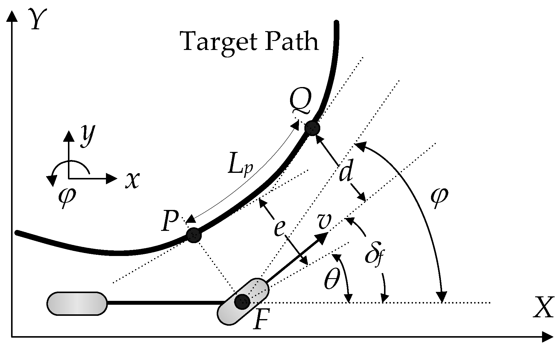
Another method widely used to generate a steering angle for autonomous driving is the Stanley method [53]. Figure 2 shows the target path and the dynamic variables used for the Stanley method. In Figure 2, the dynamic variables, v and δf, represent the velocity and steering angle of a vehicle, respectively. To generate a steering angle using the Stanley method, it is necessary to calculate the heading and lateral offset errors. The first step is to find the nearest point P on a target path from the center point of the front axle, F. Then, the lateral offset error, e, is the distance from F to P, as shown in Figure 2. The heading error, θ, is the difference between the heading angles of the vehicle and the target path at P. With those errors, the front steering angle, δf, is calculated as (4) by summing these two terms. In (4), ks is a distance gain, which is used to tune the magnitude of e.
δ f t = θ t + tan 1 k s e t v t
In this paper, a lookahead or preview function is introduced into the Stanley method. The lookahead distance Lp is calculated as (1). If Lp is zero, then this becomes (4). With Lp, the previewed point Q on the target path is obtained as shown in Figure 2. From the point Q, the lateral offset and heading errors are calculated as d and φ as shown in Figure 2. As shown in Figure 2, the heading error becomes larger and the distance error smaller than (4) if the preview function is applied on the target path. As a result, the distance error has a smaller effect on the steering angle. This can cause a slow response if the heading angles of a vehicle and a target path are identical to each other and the distance between a vehicle and the target path is small. In summary, kv is much more important than ks in (5). Let the Stanley method be denoted by STM.
δ f t = φ t + tan 1 k s d t v t

2.3. LQR

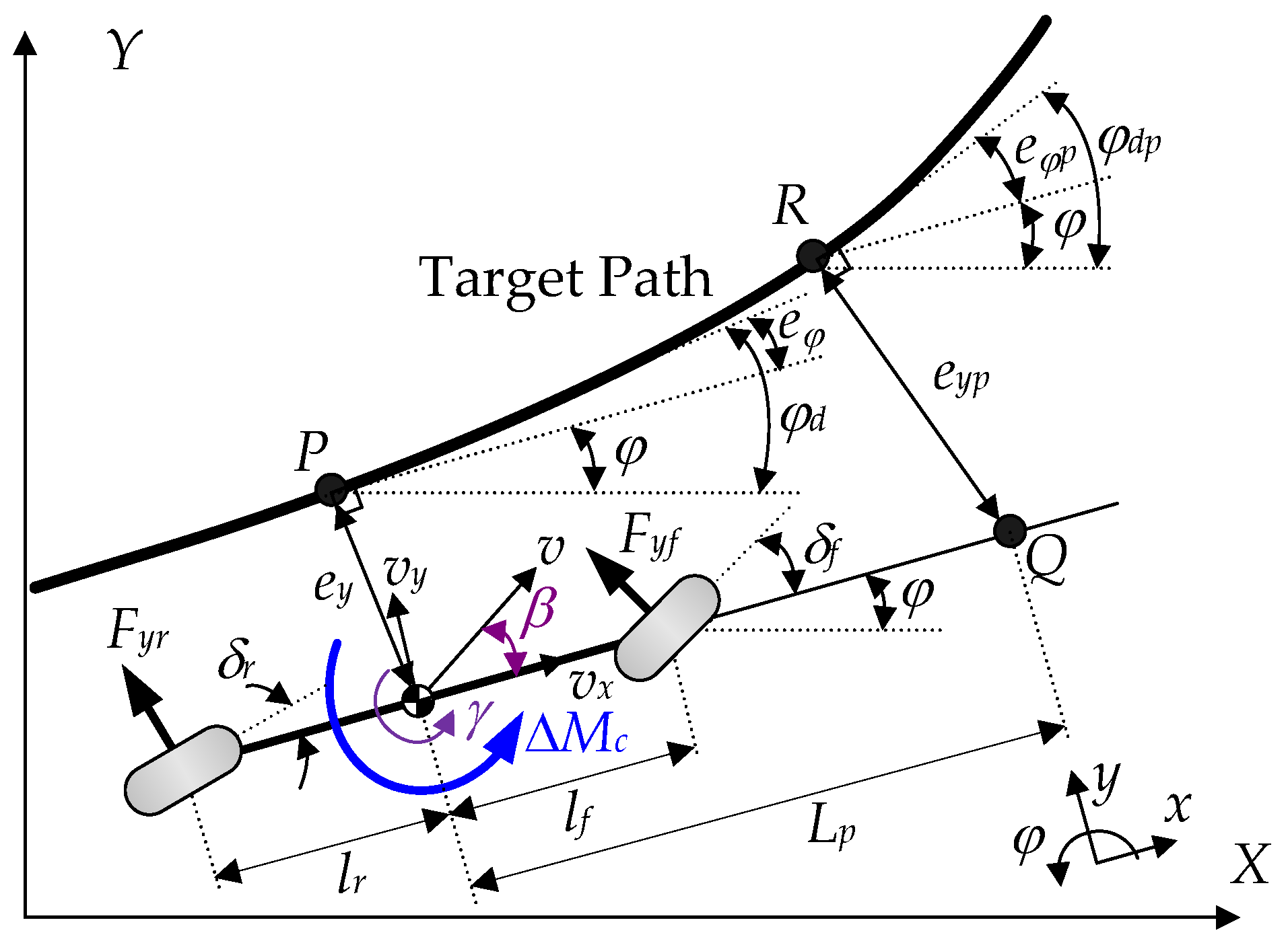
For PTC, LQR uses the state-space equation derived from heading and lateral offset errors. To derive the state-space equation, a dynamic bicycle model has been used. Figure 3 shows the coordinates and variables of the 2-DOF dynamic bicycle model used for path tracking [43]. In the model, there are two dynamic variables: the lateral velocity, vy, and the yaw rate, γ, correspondingly describing the motions of lateral and yaw directions under the assumption that the longitudinal velocity, vx, is constant. For this reason, the longitudinal motion is neglected in the bicycle model. The equations of motion for this model are derived as (6) with the state variables [44]. In (6), m and Iz are the vehicle mass and the yaw moment of inertia, respectively. The front and the rear tire slip angles, αf and αr, are defined as (7). In (6) and (7), β is the side-slip angle, which is calculated by tan−1(vy/vx) ≈ vy/vx under the assumption that vy is small or β is smaller than 10°. In (6), it is assumed that the front and the rear lateral tire forces, Fyf and Fyr, are linear to αf and αr, as shown in (8), respectively. In (8), Cf and Cr are the cornering stiffness of the front and rear wheels, respectively. In (6), ΔMc is the control yaw moment used as a control input for path and yaw rate tracking controls.
m v ˙ y + v x γ = F y f + F y r I z γ ˙ = l f F y f l r F y r + Δ M c
α f = δ f v y + l f γ v x , α r = δ r v y l r γ v x
F y f = 2 C f α f , F y r = 2 C r α r
Different from the previous works, a lookahead or preview function is introduced when calculating the heading and lateral offset errors [15,27,55,56,57,58]. Generally, the heading and lateral offset errors are defined at point P as shown in Figure 3. In this paper, a lookahead distance Lp is calculated by (1). With Lp, the point Q is obtained along the heading of a vehicle, as shown in Figure 3. With point Q, point R is obtained on the target path along the perpendicular direction to the heading of the vehicle. In this paper, the heading and lateral offset errors are calculated at point R. If Lp is set to 0, then these errors are calculated at the point P.
Let the position of the CoG of a vehicle be (x,y). The heading and lateral offset errors, i.e., eφ and ey, are defined at point P as (9) [59]. In (9), φd is the desired heading angle, defined as the heading angle of the tangential line at point P. Those at point R, i.e., eφp and eyp, are also calculated as (10) [60]. In this paper, Lp is set to a particular value less than 0.1. If vx is less than 20 m/s, the point R is located near the center of the front axle, which is nearly identical to the case of the Stanley method. For this reason, it is assumed that the heading and lateral offset errors at point P are identical to those at point R, as given in (10). Under the assumption, the state-space equation is derived from those errors at point P and that those errors at point R are used for full-state feedback control [60].
e φ = φ φ d e y = y y d
e φ p = φ φ d p φ φ d = e φ e y p = e y + L p sin e φ e y
The derivative of the desired heading angle is defined as (11), where κ is the curvature of the target path at point P in Figure 3. From those definitions, the first and second derivatives of the heading and lateral offset errors are derived as (12) [58]. With those variables, the state vector, x, the control input, u, and the disturbance, w, are defined as (13). As shown in (13), there are two types of control inputs according to FWS and 4WS, i.e., δf and [δf δr]T, respectively. From (7), (8) and (12), the state-space equations for FWS and 4WS are derived as (14) and (15), respectively. The difference between (14) and (15) is the input matrix of u. The vector-matrix form of this equation is given as (16).
φ ˙ d = v x κ
e ˙ φ = φ ˙ φ ˙ d = φ ˙ v x κ = γ v x κ e ˙ y = v y + v x e φ e ¨ φ = φ ¨ φ ¨ d = γ ˙ φ ¨ d e ¨ y = v ˙ y + v x e ˙ φ
x = e y e ˙ y e φ e ˙ φ T , u = δ f o r δ f δ r , w = κ
x ˙ = 0 1 0 0 0 η 1 m v x η 1 m η 2 m v x 0 0 0 1 0 η 2 I z v x η 2 I z η 3 I z v x x + 0 η 2 m v x 2 0 η 3 I z w + 0 C f m 0 l f C f I z u η 1 = 2 C f + 2 C r , η 2 = 2 l f C f + 2 l r C r , η 3 = 2 l f 2 C f 2 l r 2 C r
x ˙ = 0 1 0 0 0 η 1 m v x η 1 m η 2 m v x 0 0 0 1 0 η 2 I z v x η 2 I z η 3 I z v x x + 0 η 2 m v x 2 0 η 3 I z w + 0 0 C f m C r m 0 0 l f C f I z l r C r I z u
x ˙ = A x + B 1 w + B 2 u
LQ objective function is given in (17). For FWS, ρ6 is set to 0. In (17), the weight ρi is determined by Bryson’s rule, (18), where ξi is the maximum allowable value of the corresponding term [61]. This function can be represented as the vector-matrix form using the definition of the regulated output, z, as given (19). The matrices Q, N and R given in (17) are calculated by (20). The control input of LQR is calculated as (21), where P is the solution of the Riccati equation. The design parameters of LQR is the weights ρi in (17). Let the LQR with FWS and 4WS be LQRFWS and LQR4WS, respectively.
J = 0 ( ρ 1 e y 2 + ρ 2 e ˙ y 2 + ρ 3 e φ 2 + ρ 4 e ˙ φ 2 + ρ 5 δ f 2 ) d t for FWS = 0 ( ρ 1 e y 2 + ρ 2 e ˙ y 2 + ρ 3 e φ 2 + ρ 4 e ˙ φ 2 + ρ 5 δ f 2 + ρ 6 δ r 2 ) d t for 4 WS = 0 [ x u w ] T [ Q N 0 N T R 0 0 0 S ] [ x u w ] d t = 0 z T z d t
ρ i = 1 ξ i 2
z = C x + D 11 w + D 12 u = d i a g ρ 1 , ρ 2 , ρ 3 , ρ 4 0 1 × 4 x + 0 5 × 1 w + 0 4 × 1 ρ 5 u for FWS = d i a g ρ 1 , ρ 2 , ρ 3 , ρ 4 0 2 × 4 x + 0 6 × 1 w + 0 4 × 2 d i a g ρ 5 , ρ 6 u       for 4 WS
Q C T C , N C T D 12 , R D 12 T D 12 , S D 11 T D 11
u = K L Q R x = R 1 B 2 T P x

2.4. PID Control

The PID controller is designed with the heading and lateral offset errors defined at point R, as given in Figure 3. With the heading and lateral offset errors, the control inputs, i.e., uy and uφ, are calculated as (22). The control input of the PID controller is the sum of these inputs. In PID controller, the control input is the steering angle of the front wheels. The design parameters of PID controller are six gains as given in (22).
u y = K p y e y p + K i y e y p d t + K d y d e y p d t u φ = K p φ e φ p + K i φ e φ p d t + K d φ d e φ p d t

2.5. SMC

SMC also uses the state-space equation, (16). The sliding surface, s, is defined as (23), where M is the matrix representing the weights on the state variables. Note that s is scalar. The convergence or stability condition of the sliding surface is given as (24). By combining (23), (24) and (16), (25) is obtained. From (25), the control input of SMC is derived as (26) [15,62,63]. In (26), (•)+ is the pseudo-inverse of a matrix (•). In this paper, the disturbance feedforward term, i.e., the second term on the right side of (26) is neglected. The design parameters of SMC are M and KSMC.
s = M x
s ˙ = K S M C s K S M C > 0
s ˙ = M x ˙ = M A x + B 1 w + B 2 u = K S M C M x
u = M B 2 + M A + K S M C M x M B 2 + M B 1 w

2.6. MPC

MPC has been extensively used for PTC [64]. MPC also uses the discretized version state-space equation from (16). The discrete-time state-space equation is shown in (27) with the sampling time, Ts. The matrices Γ, Ω and Φ in (27) are calculated by (28). Hereafter, it is assumed that there are no disturbances, i.e., wk = 0 in (27). The LQ objective function, (17), is converted into the discrete-time version as (29) under the assumption that there are no cross-product terms among the state variable, the control input and the disturbance. In (29), N is the prediction horizon. Let the current state be x0, which is obtained from the lookahead point. At time instant k, the state is calculated as (30) from (27). New vectors and matrices are defined as (31) by expanding (30) for each time instant. With those definitions, the state-space equation and LQ objective function are calculated as (32) and (33), respectively. By replacing X with (32), the LQ objective function, (33), is calculated by (34). The maximum steering angle, δmax, is imposed on the control input U, as given in (35). There are no constraints on the steering angular rate. This is a quadratic programming problem with the optimization variable U, the objective function JMPC, and the bounded constraints [64]. In this paper, the MATLAB command quadprog() was used to find the optimum solution of this problem. After obtaining the optimum solution U, MPC uses the first element of U, i.e., u0 as the control input. In this paper, Ts and N are set to 0.01 s and 50, respectively.
x k + 1 = Γ x k + Ω w k + Φ u k
Γ = I + A T s , Ω = B 1 T s , Φ = B 2 T s
J M P C = k = 0 N 1 x k T Q x k + u k T R u k
x k + 1 = Γ k x 0 + i = 0 k 1 Γ i 1 Φ u k i 1
X = [ x 1 x 2 x 3 x N ] , Γ ¯ = [ Γ Γ 2 Γ 3 Γ N ] , Φ ¯ = [ Φ 0 0 0 0 Γ Φ Φ 0 0 0 Γ 2 Φ Γ Φ Φ 0 0 0 Γ N 1 Φ Γ N 2 Φ Γ N 3 Φ Φ ] , U = [ u 0 u 1 u 2 u N 1 ] Q ¯ = [ Q 0 0 0 Q 0 0 0 Q ] , R ¯ = [ R 0 0 0 R 0 0 0 R ]
X = Γ ¯ x 0 + Φ ¯ U
J M P C = x 0 T Q x 0 + X T Q ¯ X + U T R ¯ U
J M P C = U T Φ ¯ T Q ¯ Φ ¯ + R ¯ U + 2 x 0 T Γ ¯ T Q ¯ Φ ¯ U
δ max U δ max

2.7. Yaw Rate Tracking Control Method

Generally, PPM, STM and the PID controller are designed for a FWS vehicle. For this reason, these methods cannot be applied to a 4WS vehicle. To use 4WS for path tracking, it is necessary to convert the path tracking problem into the yaw rate tracking one [27,36,37]. This method calculates the reference yaw rate from a steering angle obtained from PPM, STM and PID controller. Then, a yaw rate tracking controller is designed in order to make a vehicle follow the reference yaw rate [36,37].
The reference yaw rate, γd, is calculated from the front steering angle, δf, as given in (36) [43]. In (36), Kγ represents the steady-state yaw rate gain. Generally, γd is bounded by (37), which is determined with μ and vx. In the previous study, it was shown that path tracking and lateral stability can be simultaneously met by setting Kγ to an appropriate value, regardless of Cf and Cr in (36) [37].
γ d = C f C r l f + l r v x C f C r l f + l r 2 + m v x 2 l r C r l f C f δ f = K γ δ f
γ d 0.85 μ g v x
The yaw moment controller calculates ΔMc, as given in (6) and Figure 3. The yaw rate error, γe, is the difference between the reference and actual ones, i.e., γγd. The sliding or error surface is defined as (38). To make this surface converge to zero, the convergence condition of (39) should be satisfied [36,37,45,46,48]. From (6), (38) and (39), ΔMc is computed as (40).
s = γ γ d
s ˙ = K c s K c > 0
Δ M c = I z γ ˙ d l f F y f + l r F y r I z K c γ γ d
Once ΔMc is calculated, the lateral tire forces, ΔFyf and ΔFyr, as given in (6) and Figure 3, are to be determined, which are converted into the steering angles of front and rear wheels. This is called control allocation or yaw moment distribution, which is a procedure used to determine the tire forces needed to generate ΔMc. For control allocation, this paper adopts the weighted pseudo-inverse based control allocation (WPCA) [36,37,45,46,48]. For 4WS, the force-moment equilibrium between ΔFyf, ΔFyr and ΔMc, as given in Figure 3, is represented as (41). The vector q is the solution of WPCA; (41) is the equality constraint of WPCA.
2 l f cos δ f 2 l r cos δ r h Δ F y f Δ F y r q = Δ M c
The objective function of WPCA is defined as (42). In (42), μ·Fzi in the denominator represents the radius of friction circles. To calculate this value, the tire-road friction coefficient, μ, and the vertical tire force at each wheel, Fzi, should be measured or estimated. In this paper, it is assumed that μ is constant and known a priori. For flat road surfaces, the vertical tire forces can be estimated using longitudinal and lateral accelerations, as given in [64,65,66]. The quadratic programming with equality constraints can be solved algebraically as (43) by using the Lagrange multiplier technique. Tire forces, obtained from qopt in (43), should be converted into the steer angles of 4WS.
J = Δ F y f 2 μ F z 1 2 + Δ F y f 2 μ F z 2 2 + Δ F y r 2 μ F z 3 2 + Δ F y r 2 μ F z 4 2 = q T W q W = diag 1 μ F z 1 2 + 1 μ F z 2 2 , 1 μ F z 3 2 + 1 μ F z 4 2
q o p t = Δ F y f Δ F y r = W 1 h T h W 1 h T 1 Δ M c
After obtaining the lateral tire forces, ΔFyf and ΔFyr, from WPCA, the next step is to determine the steering angles of 4WS from these forces. For this purpose, it is necessary to use the definitions of the slip angles and the lateral tire force, (7) and (8), respectively. From (8), the derived slip angle ϕ is calculated by (44) [37,46]. In (44), σ is the parameter used to tune the magnitude of the cornering stiffness, Ci. In fact, σ can be regarded as a slip ratio [18]. By combining (44) with (7), the steering angles of 4WS, i.e., δf and δr, are calculated as (45) [36,37]. To calculate the steering angles with (45) and to calculate the side-slip angle, the lateral velocity, vy, should be measured or estimated. In previous studies, various estimation methods have been proposed for this purpose. Among them, the Kalman Filter-based method is adopted in this paper [67].
ϕ i = Δ F y i σ C i , i = f , r
δ f = α f + v y + l f γ v x = ϕ f + v y + l f γ v x δ r = α r + v y l r γ v x = ϕ r + v y l r γ v x

3. Performance Measures for Path Tracking Control

To date, several measures have been proposed for path tracking. The most simple and straightforward way is to use the magnitude of heading and lateral offset errors. However, these measures cannot represent the responsiveness or agility of the controller. Another simple measure for path tracking is the magnitude of the steering angle and its angular rate, which represent the driver’s steering effort. However, the driver does not move the steering wheel in autonomous vehicles. For this reason, these measures are not considered in this paper.
In this paper, the target path is defined as (46), which represents a double lane change maneuver [11,13,14,16,19,20,23,24,25,28,29,31]. The target path was shifted to the right of 20 m from the original one. The black line in Figure 4 shows this path. For the target path given in (46), five new measures are defined as (47) to represent path tracking performance: the center offset, ΔX, the lateral offset, ΔY, the percentage over-shoot, OS%, response delay, ΔDX, and the settling delay, ΔSX, as depicted in Figure 4. In (47), X(A) and Y(A) represent the x and y positions of point A, respectively. Basically, the smaller the absolute values of these measures the better.
Y r e f X = 0 if X < 20 4.05 2 1 + tanh z 1 5.7 2 1 + tanh z 2 if X 20 ψ r e f X = 0 if X < 20 tan 1 4.05 1 cosh z 1 1.2 25 5.7 1 cosh z 2 1.2 21.95 if X 20 where z 1 = 2.4 25 X 37.19 , z 2 = 2.4 21.95 X 76.46
Δ X = X D X A Δ Y = Y D Y A Δ D X = X E X B Δ S X = X G X C O S % = Y F 1.65 1.65 + Y A × 100
In Figure 4, X(A) and Y(A) are 73.2 m and 3.53 m, respectively. ΔX and ΔY represent agility and reachability, respectively. A negative value of ΔX means that a vehicle has reached its peak, i.e., point D, before point A, as shown in Figure 4. This means a fast response. For the reason, ΔX can be regarded as a delay in reaching the peak. For good path tracking or collision avoidance, a negative ΔX is desirable. For this reason, it is regarded as satisfactory if ΔX is less than 0 m. A negative value of ΔY means that the first peak of the vehicle trajectory, i.e., Y(D), did not reach Y(A), as shown in Figure 4. For good path tracking, ΔY should be larger than −0.05 m.
OS% represents the lateral or yaw damping, which is equivalent to agility. In Figure 4, the y-position value of the centerline of the lower lane is −1.65 m. Let the tread of the vehicle be 1.6 m. Then, the vehicle will be inside this lane under the condition that Y(F) is larger than −2.5 m, which means that the maximum overshoot is 0.85 m. For this reason, it is satisfactory if OS% is less than 16%.
ΔDX is equivalent to the response delay in control theory, which represents the agility or response speed of the vehicle motion in path tracking. Points B and E correspondingly represent the cross points of the target path and vehicle trajectory to the horizonal line at the y-axis, as shown in Figure 4. X(B) is a fixed value of 91.5 m.
ΔSX is equivalent to the settling time in control theory, which represents the convergence speed of the vehicle motion to a target value or how fast the vehicle converges to a particular range around the target position. When calculating ΔSX, a ±0.05 m range around a target position, i.e., −1.65 m, is set in this paper. In other words, if the CoG of the vehicle converges into the range between −1.65 m ± 0.05 m, then it is regarded that the vehicle trajectory is converged to the target path and that the stability of the vehicle is maintained. In Figure 4, points C and G represent the cross points of the target path and the vehicle trajectory to the horizontal line of the y-position of −1.6 m or −1.7 m, respectively. In Figure 4, X(C) is 109.7 m. The target path reaches −1.65 m at 126.3 m. The distance between point C and the converging point is 16.6 m. As shown in Figure 4, the target path has no overshoots. For the reason, it is satisfactory if ΔSX is less than 16 m.
On low-friction roads, a vehicle loses its lateral stability easily due to small lateral forces. Generally, lateral stability is represented by the side-slip angle, β. In other words, lateral stability refers to the ability to prevent β from diverging. In real vehicles, lateral stability is maintained by maintaining β within a certain range, e.g., 3° [45]. Besides the side-slip angle, the side-slip angular rate has been also used as a criterion for lateral stability [19]. Moreover, it can be used as a measure for ride comfort. Generally, the smaller the value of β the better, in terms of lateral stability and ride comfort. For this reason, the side-slip angle and its rate are adopted as a measure for lateral stability and ride comfort. Let the maximum absolute values of the side-slip angle and its rate be MASSA and MASSAR, respectively.

4. Simulation and Validation

A simulation is performed to compare the path tracking performance of the designed controllers. The path tracking controllers were implemented on a MATLAB/Simulink environment. The simulation was conducted via CarSim [68]. A target path, (46), representing a double lane change was adopted as a test scenario [11,13,14,16,19,20,23,24,25,28,29,31]. For the simulation, the built-in F-segment model in CarSim software was chosen [68]. This model is nonlinear with 27 degrees of freedom, including a single sprung mass, four wheels, four suspensions and a steering mechanism. The configurations of suspensions in this model are independent front and solid rear axles. From the model, the values of each parameter in the 2-DOF dynamic bicycle model are obtained as given in Table 1. As shown in Table 1, Cr is larger than Cf, which means the vehicle understeers. To model the steering actuators of FWS and 4WS, this paper adopted the 1st-order system with a time constant of 0.01. The initial speed was set to 60 km/h. The built-in speed controller given in CarSim was applied while driving to maintain a constant speed. The maximum steering angles of the front and rear wheels were set to 30°.
The four sets of simulations were carried out to compare the path tracking performance of the designed controllers. The first was performed for vehicles with FWS and 4WS on high-μ roads, where μ was set to 0.85. Under that condition, the controllers were tuned such that ΔX, OS%, ΔDX and ΔSX are minimized under the condition that ΔY is larger than −0.05 m. The second set of simulations was performed on low-μ roads, for which μ was set to 0.4. In this set of simulations, the parameters and gains tuned in the first simulation were used. The third was performed on low-μ roads, where the controllers were tuned for the identical purpose to the first one. This is the main part of this paper. The fourth is done on high-μ roads, for which μ was set to 0.85. In this set of simulations, the parameters and gains tuned in the third simulation were used.
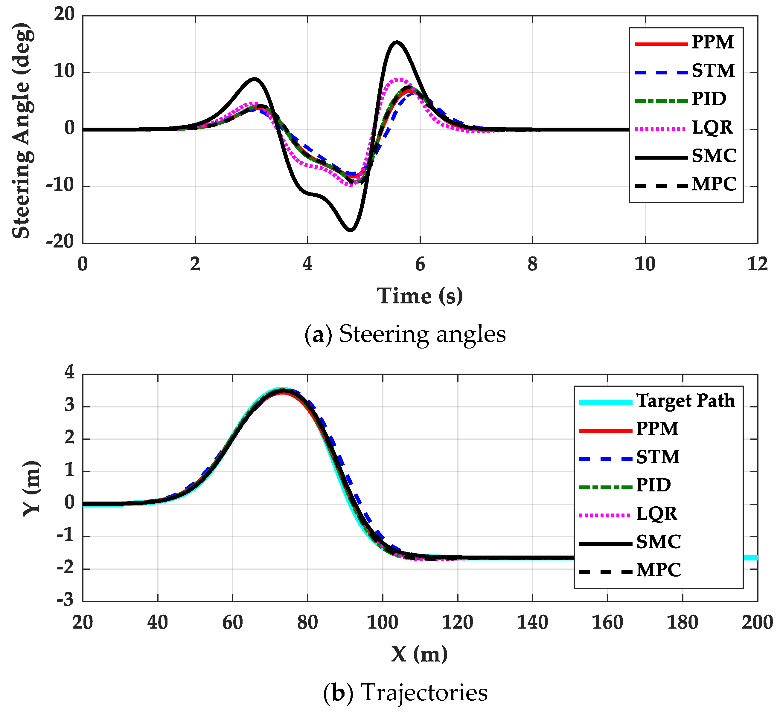
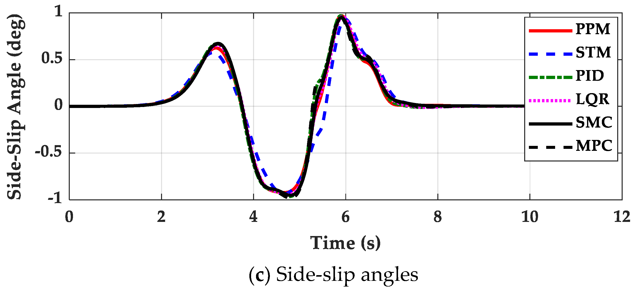
The first set of simulations was performed on high-μ roads with the path tracking controllers for vehicles with FWS and 4WS. Figure 5 shows the simulation results of each controller for the FWS vehicle. Table 2 and Table 3 show the performance measures of each controller for FWS and 4WS vehicles, respectively. As shown in Figure 5b,c, the controllers show nearly identical performance in terms of path tracking and lateral stability. However, the steering angles are different from one another. As shown in Table 2 and Table 3, the simulation results of each controller for 4WS vehicle are also nearly identical to those for FWS vehicles. The notable difference among those results of Table 2 and Table 3 is that 4WS or RWS can reduce the side-slip angle, as reported in the literature [36,45,46]. Excepting this fact, there were few differences between FWS and 4WS vehicles. These results imply that 4WS is not effective in improving path tracking performance over FWS.
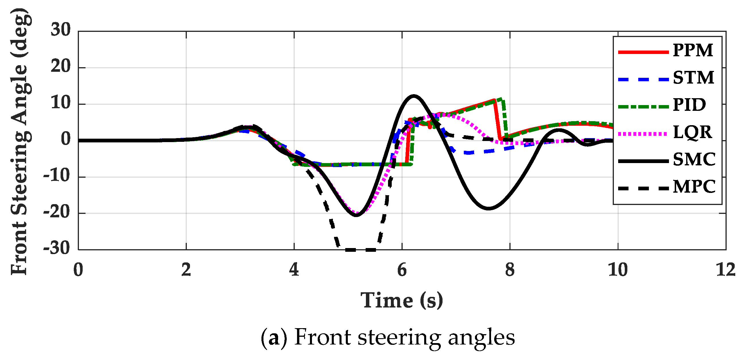
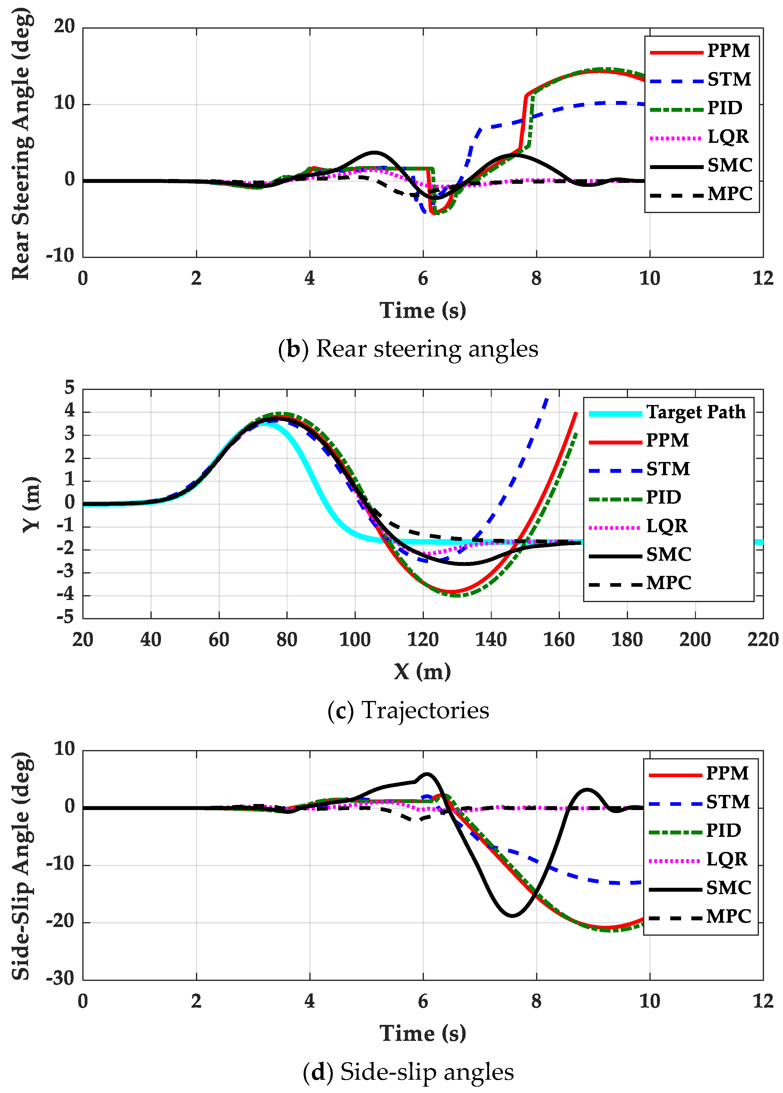
The second set of simulations was performed on low-μ roads with the path tracking controllers for vehicles with FWS and 4WS. In this set of simulations, the parameters and gains tuned on high-μ roads in the first set of simulations were used. Figure 6 and Figure 7 show the simulation results of each controller for FWS and 4WS vehicles, respectively. Table 4 and Table 5 show the performance measures of each controller for FWS and 4WS vehicles, respectively. As shown in Figure 6 and Figure 7, the path tracking performance of each controller was severely deteriorated on low-μ roads. As shown in Figure 6, the controllers for the FWS vehicle did not diverge in spite of poor performance. As shown in Figure 7, the PPM, STM and PID for the 4WS vehicle diverged. On the contrary, the path tracking controllers designed with the state-space model, i.e., LQR, SMC and MPC, did not diverge. Regarding lateral stability, the controllers, PPM, STM, PID and SMC, could not maintain lateral stability on low-μ roads. These facts can be found in Table 4 and Table 5. As shown in Table 5, LQR and MPC did not diverge and showed relatively good path tracking performance. From those results, it can be concluded that the path tracking controller designed for high-μ roads cannot be used on low-μ ones.
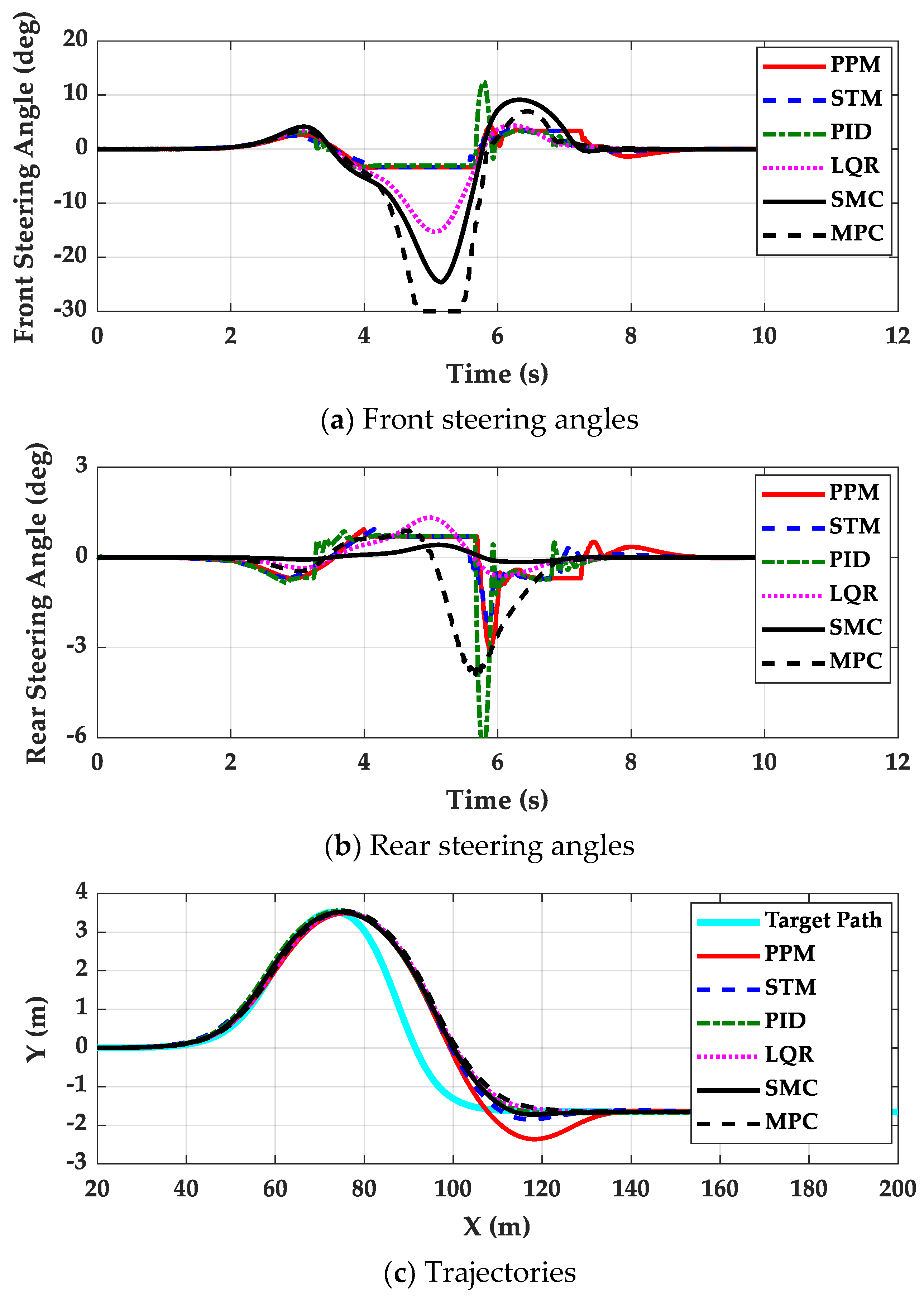
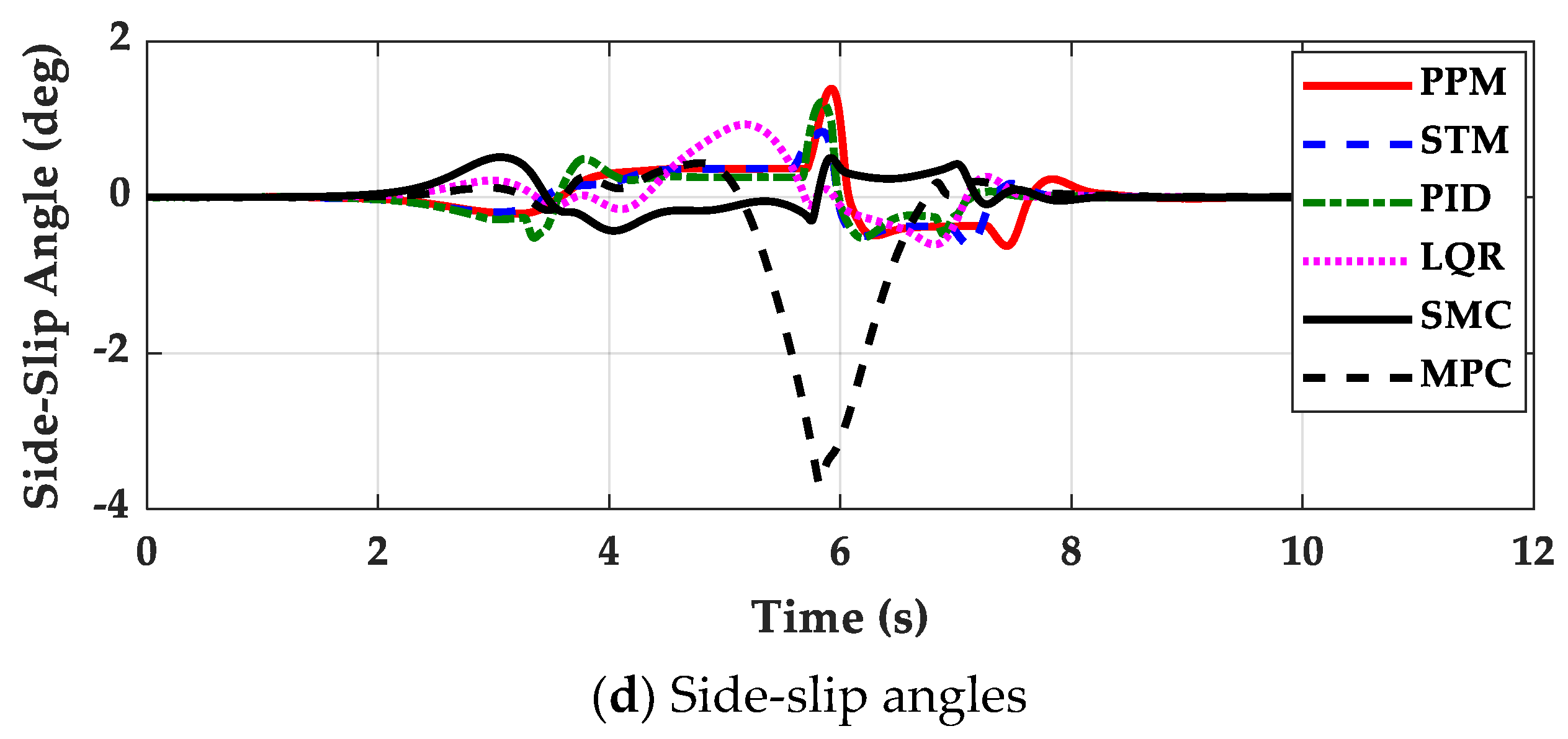
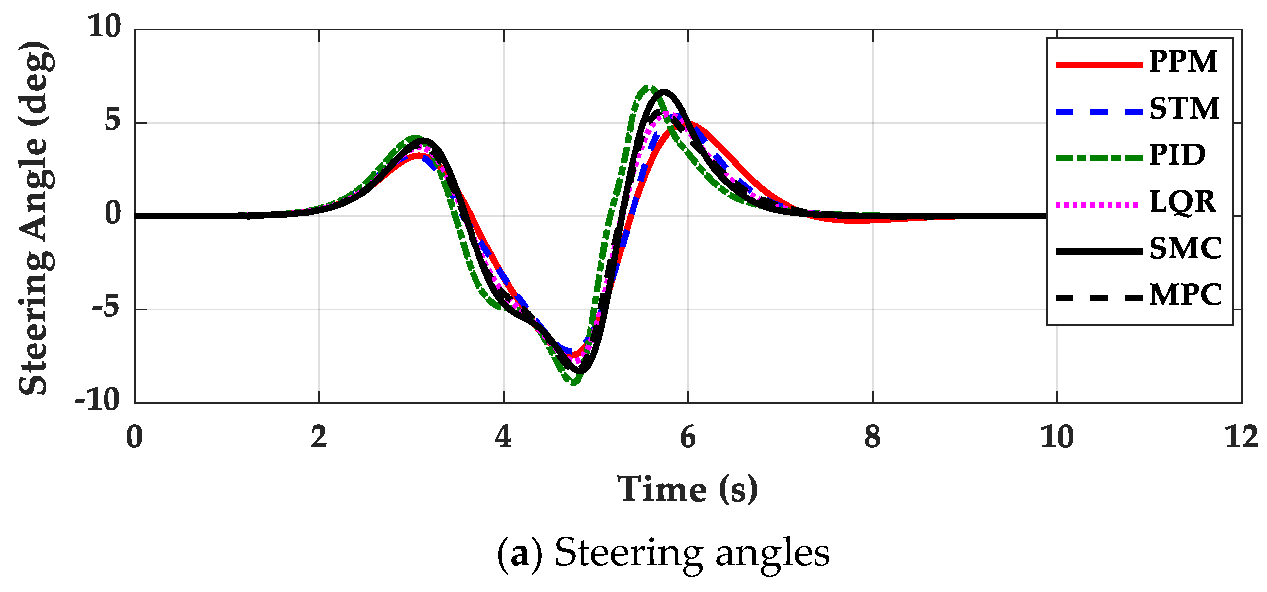
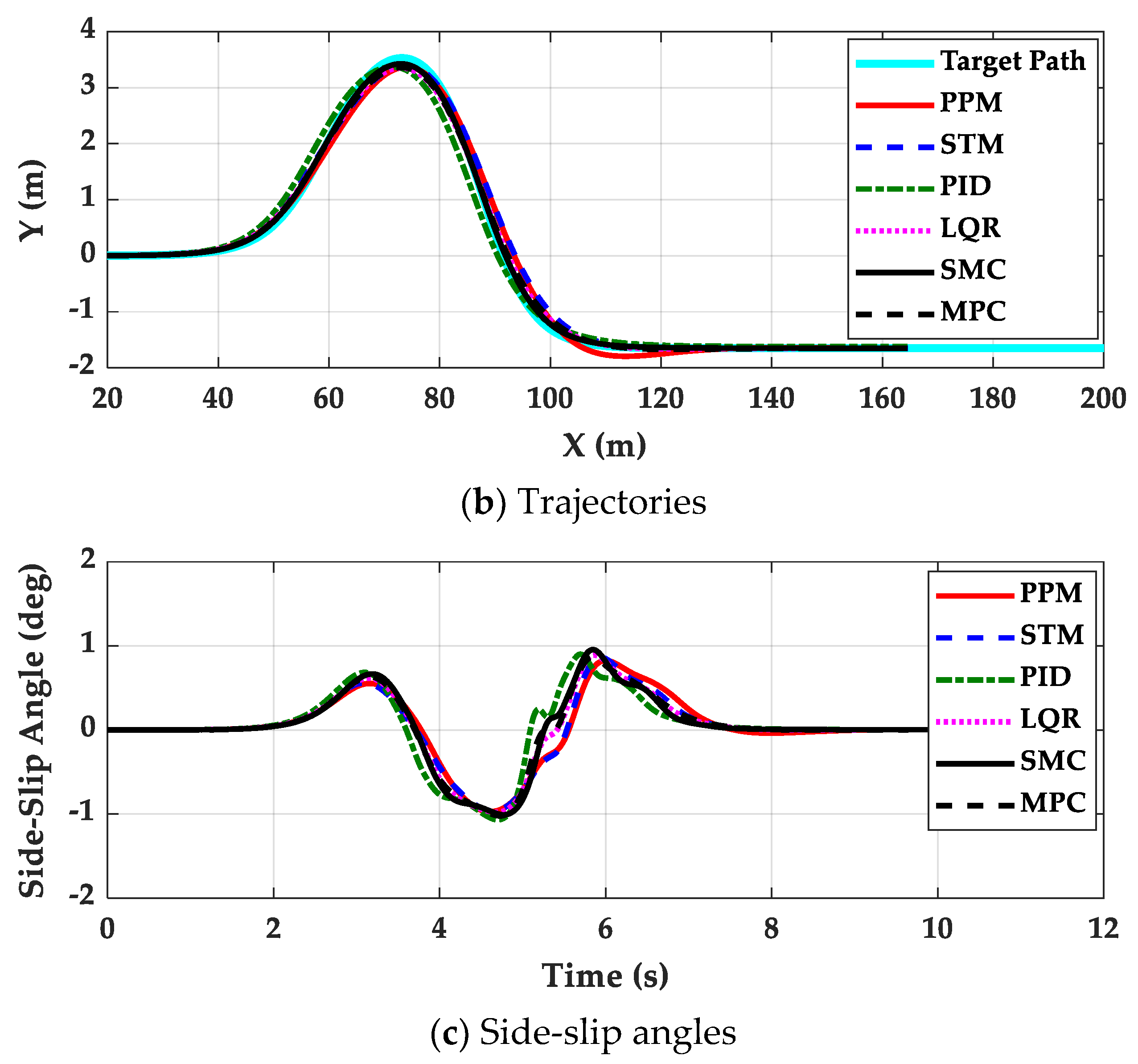
The third set of simulations was performed on low-μ roads with path tracking controllers for FWS and 4WS vehicles. In this set of simulations, the parameters and gains were tuned on low-μ roads. When carrying out the simulation with a 4WS vehicle, the steering angles of the rear wheels were limited to 10°. Figure 8 and Figure 9 show the simulation results of each controller for FWS and 4WS vehicles, respectively. Table 6 and Table 7 summarize the performance measures of each controller for FWS and 4WS vehicles, respectively.
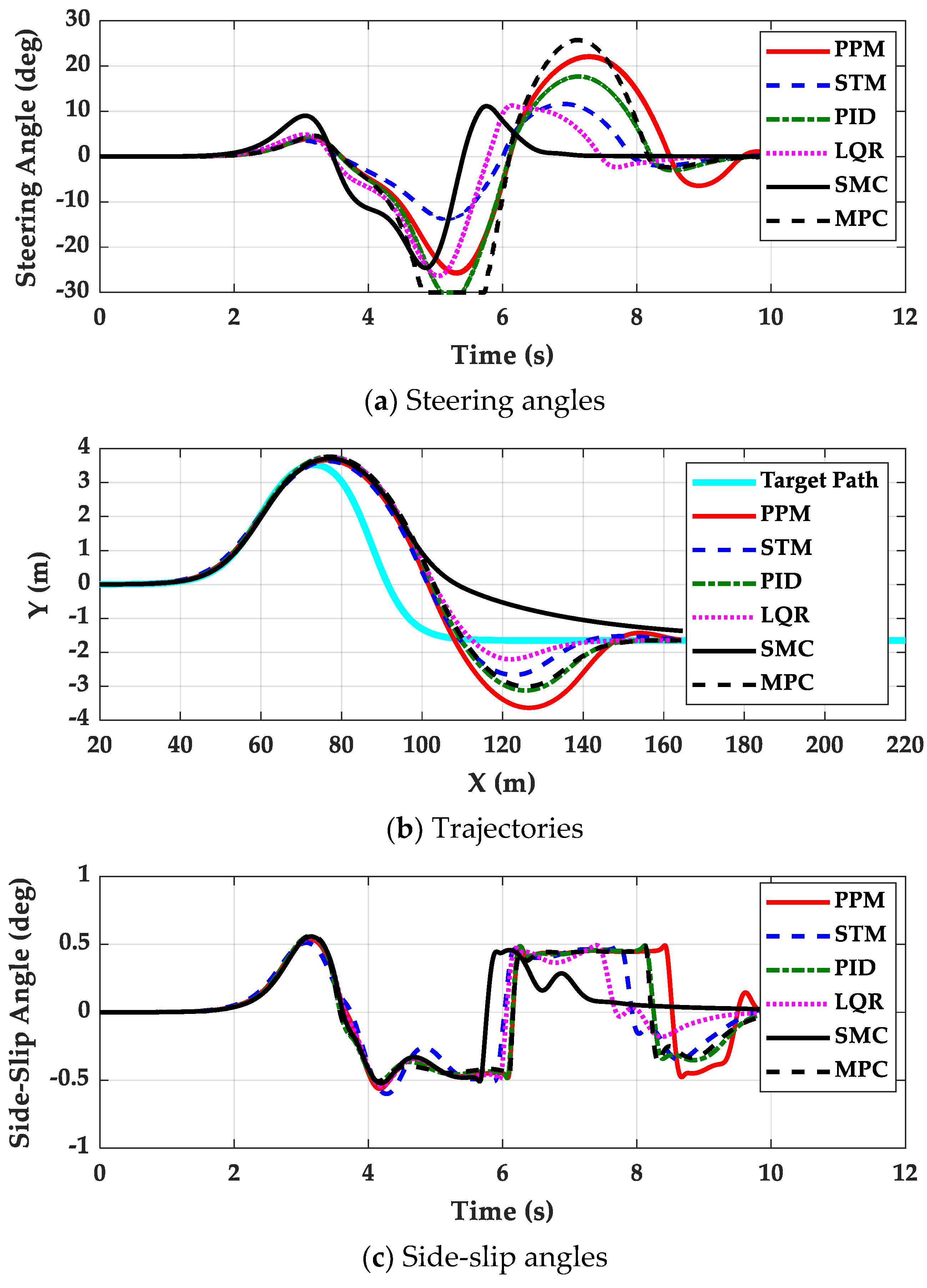
Comparing the results between Figure 6 and Figure 7 and Figure 8 and Figure 9, the path tracking performance was clearly improved by the controllers. However, ΔX, ΔDX and ΔSX were deteriorated due to low-μ conditions, as shown in Table 2, Table 3, Table 6 and Table 7. On the high-μ road, there were few differences among path tracking controllers. On the contrary, LQR, SMC and MPC show better performance than PPM, STM and PID on the low-μ road, which was expected from the results in Figure 7 and Table 5. As shown in Figure 8c and Table 6, the side-slip angles of FWS vehicle were kept low, which means that lateral stability is preserved well by the controllers. This fact implies that a switching or coordination scheme between path tracking and lateral stability on low-μ roads is not needed.
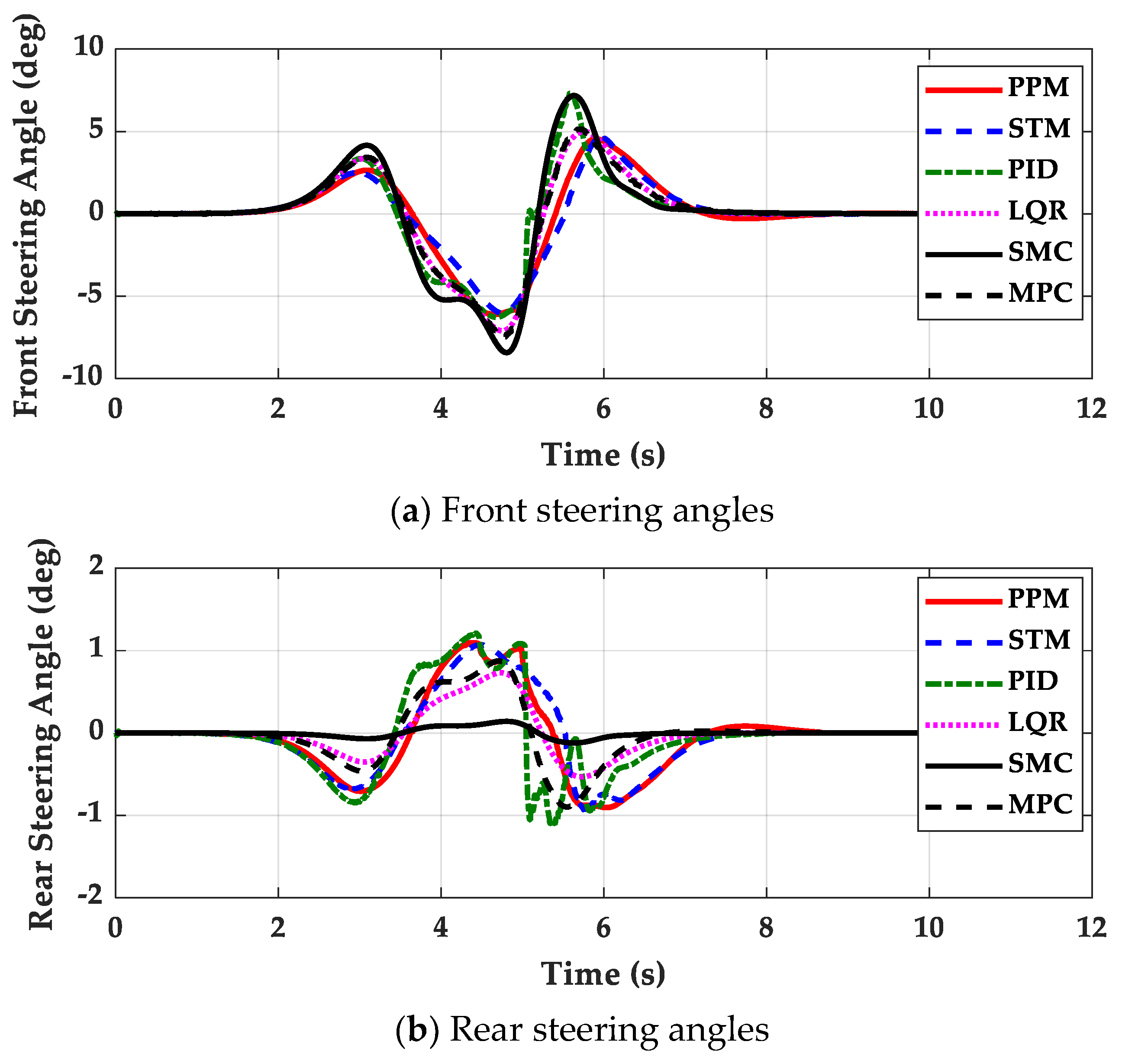
Comparing the data between Table 6 and Table 7, 4WS has few advantages over FWS, except ΔSX. In other words, the role of 4WS for path tracking is to improve the convergence speed to the target path. However, 4WS can make a vehicle more unstable, which generates large MASSAR. Comparing the data among Table 2, Table 3, Table 6 and Table 7, it can be found that 4WS reduced MASSA on the high-μ road. However, 4WS increased MASSA on low-μ roads. As shown in Figure 9a, the steering angle of MPC was larger than the others. Due to the larger steering angle of MPC, the lateral tire forces were saturated. This is caused by the fact that the larger weights on the lateral offset errors in the LQ objective function can give good path tracking performance and that, as a consequence, the heading errors cannot be reduced. In this case, the steering angles of the front and rear wheels move in the same direction. For this reason, there is little yaw motion and larger lateral motion. As a result, the side-slip angle of MPC became much larger. This is also common in LQR and SMC in the case of using RWS. To cope with this problem, the steering angles of rear wheels were limited to 10° during the simulation with the 4WS vehicle. If these are not limited, the side-slip angle will become much larger, which means that lateral stability deteriorates. From these results, it can be concluded that RWS or 4WS are not recommended in LQR, SMC and MPC for path tracking on low-μ roads.
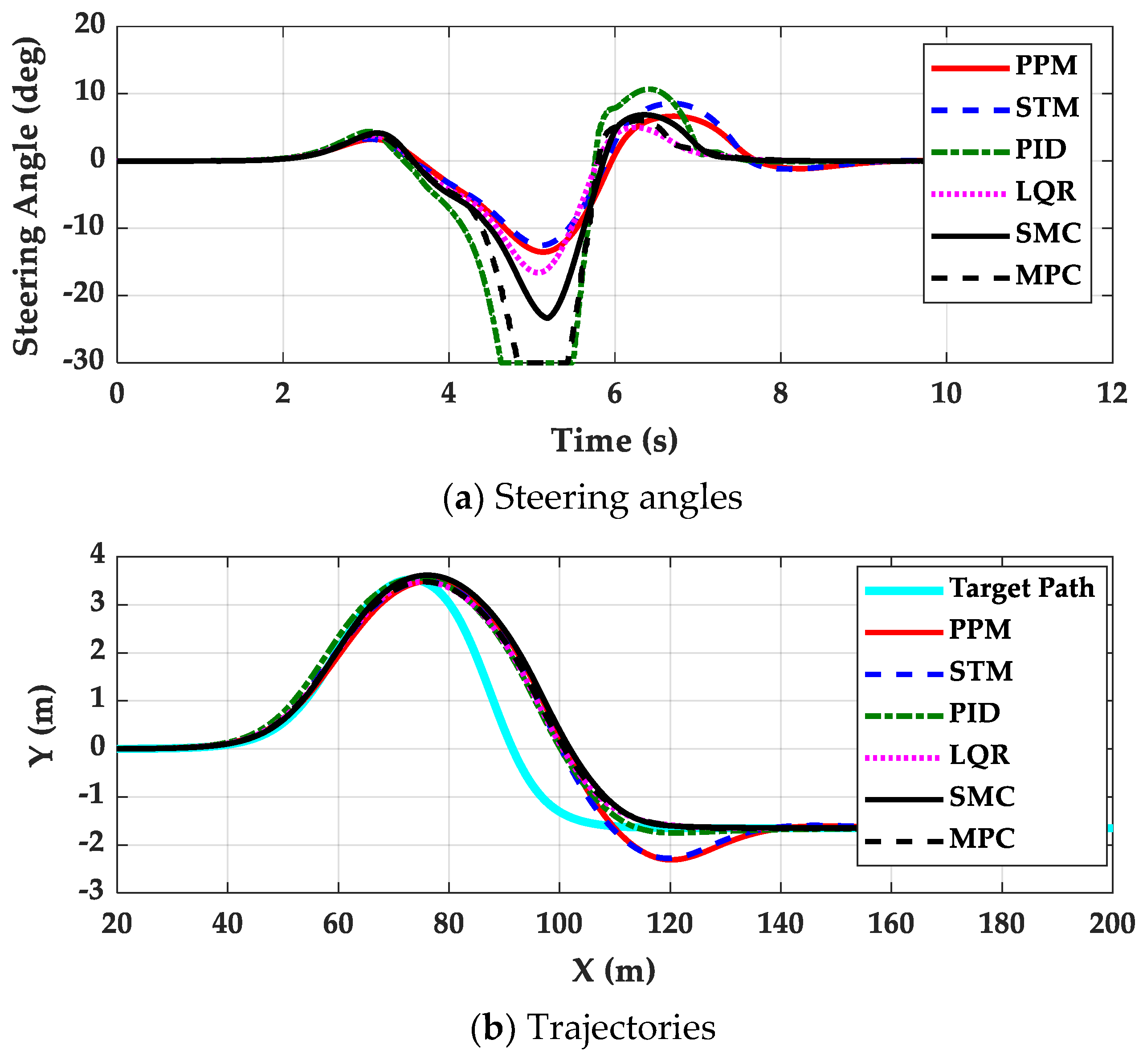
The fourth set of simulations was performed on the high-μ road with the controllers tuned for the low-μ one in the third simulation. In this set of simulations, μ was set to 0.85, which means a dry asphalt road. Figure 10 and Figure 11 show the results of the fourth set of simulations for FWS and 4WS vehicles, respectively. Table 8 and Table 9 summarize the simulation results for FWS and 4WS vehicles, respectively.
As shown in Figure 10 and Figure 11 and Table 8 and Table 9, it can be found that the path tracking controllers tuned on the low-μ road show relatively good performance, compared with those in Figure 5 and Table 2 and Table 3. ΔY and ΔSX in Figure 10 and Figure 11 are worse than those in Table 2 and Table 3. Especially, LQR, SMC and MPC, designed with the state-space model in the low-μ condition, show nearly equivalent performance to those designed for the high-μ one. These results mean that the path tracking controllers tuned on the low-μ road can be directly used on the high-μ one. Comparing the data of Table 6, Table 7, Table 8 and Table 9, it can be found that MASSA and MASSAR remain low regardless of road surface friction for identical gains. These results mean that any switching or coordination schemes between path tracking and lateral stability on the low-μ road are not needed any longer. On the other hand, the path tracking controllers tuned on the high-μ road show poor performance on the low-μ one, as shown in Table 2, Table 3, Table 4 and Table 5. From these results, it can be concluded that the controllers designed on low-μ roads can be used on high-μ ones under the assumption that emergency maneuvers for collision avoidance are not needed. Moreover, it can be also concluded that a switching or coordination scheme between path tracking and lateral stability on low-μ roads is not needed if the controllers designed on low-μ roads are adopted.

5. Conclusions

The aim of this study is to investigate the performance of the path tracking controllers under low-friction conditions for FWS and 4WS vehicles. For this purpose, the pure pursuit method, Stanley method, PID control, LQR, SMC and MPC were designed. To evaluate the path tracking performance of these controllers, new performance measures for path tracking were proposed. Simulations were performed with these controllers for path tracking on low-μ roads and the performance measures were evaluated from the simulation results. From the results, three issues were addressed as follows:
  • The controllers presented in this paper are effective for path tracking on low-μ roads because those gave good path tracking performance while maintaining lateral stability. This means that a switching or coordination scheme between path tracking and lateral stability is not needed for path tracking on low-μ roads.
  • The controllers designed on low-μ roads can be used on high-μ ones, except the emergency maneuver for collision avoidance. However, the reverse does not hold. For this reason, it is desirable that the path tracking controller should be designed for low-μ roads.
  • The 4WS or RWS vehicle is not recommend for path tracking because there are few particular advantages in using 4WS or RWS. If 4WS is used with LQR, SMC and MPC, it is desirable that the steering angles of rear wheels for these controllers should be limited to very small values. However, this will make the performance of these controllers with 4WS nearly identical to those with FWS.
The limitation of this study is that parameter uncertainty was not considered in controller design procedure. Especially, the cornering stiffness and vehicle speed have a large effect on path tracking performance. To cope with problems, a robust controller is needed. As a natural consequence of the robustness to parameter uncertainty, the control performance is quite sensitive to the change in weight in the LQ objective function. In the future, a robust controller design is needed to cope with parameter uncertainty and sensitivity of weights to control performance. Moreover, simulation studies on various speeds, routes and road surface conditions should be conducted. Furthermore, a study on the effects of actuator dynamics and several actuator configurations of 4WS, 4WIS, 4WIB and 4WID on path tracking performance will be conducted. Especially, more detailed modeling and control schemes on a steering actuator used for 4WS and 4WIS will be considered in future work. Through this study, a path tracking controller can be designed such that both the path tracking and lateral stability of self-driving vehicles in very high-speed ranges are satisfied.

Author Contributions

J.L. conceptualized the main idea and designed this study. S.Y. participated in formulating the idea, as well as validating the proposed method and results. S.Y. implemented the methodology and drafted the manuscript. All authors have read and agreed to the published version of the manuscript.

Funding

This work was supported by the Ministry of Education through the National Research Foundation of Korea (NRF) under the Basic Science Research Program (NRF-2019R1A6A1A03032119).

Data Availability Statement

Not applicable.

Conflicts of Interest

The authors declare no conflict of interest.

Nomenclature

4WS4-wheel steering
4WIS4-wheel independent steering
4WIB4-wheel independent braking
4WID4-wheel independent drive
FWSfront wheel steering
LQRlinear quadratic regulator
MPCmodel predictive control
PIDproportional-integral-derivative
PPMpure pursuit method
PTCpath tracking control
RWSrear wheel steering
SMCsliding mode control
STMStanley method
Cf, Crcornering stiffness of front/rear tires (N/rad)
Cicornering stiffness of each wheel (N/rad)
ey, eφlateral offset error (m) and heading error (rad)
Fx, Fy, Fzlongitudinal, lateral and vertical tire forces (N)
Fyf, Fyrlateral forces of front and rear wheels (N)
ggravitational acceleration constant (=9.81 m/s2)
Izyaw moment of inertial (kg·m2)
Kcgain of sliding mode control for yaw rate tracking
Kpy, Kiy, KdyP-, I- and D-gain on lateral offset error in PID controller
K, K, KP-, I- and D-gain on heading error in PID controller
KSMCgain of sliding mode control for path tracking
ksdistance gain in Stanley method
kvvelocity gain
Kγsteady−state yaw rate gain
Lwheel base (m)
Lplookahead distance (m)
lf, lrdistance from C.G. to front and rear axles (m)
mvehicle total mass (kg)
Nprediction horizon of MPC
Tssampling time of the discrete-time model used in MPC
vvehicle speed (m/s)
vx, vylongitudinal and lateral velocities of a vehicle (m/s)
ylateral displacement (m)
ydtarget displacement (m)
Yrefreference lateral displacement of the target path (m)
αf, αrtire slip angles of front and rear wheels (rad)
βside-slip angle (rad)
δf, δrfront and rear steering angles (rad)
δmaxmaximum steering angle (rad)
ΔFyicontrol tire force obtained from WPCA (N)
ΔMccontrol yaw moment (Nm)
ΔXcenter offset (m)
ΔYlateral offset (m)
OS%percentage overshoot
ΔDXresponse delay (m)
ΔSXsettling delay (m)
γ, γdreal and reference yaw rates (rad/s)
κcurvature of a path at a particular point (1/m)
ξimaximum allowable value of weight in LQ objective function
ϕiderived slip angle (rad)
φheading angle (rad)
φdtarget heading angle (rad)
Ψrefreference heading angle of the target path (m)
ρiweight in LQ objective function
σequivalent slip ratio
μtire-road friction coefficient

References

  1. Montanaro, U.; Dixit, S.; Fallaha, S.; Dianatib, M.; Stevensc, A.; Oxtobyd, D.; Mouzakitisd, A. Towards connected autonomous driving: Review of use-cases. Veh. Syst. Dyn. 2019, 57, 779–814. [Google Scholar] [CrossRef]
  2. Yurtsever, E.; Lambert, J.; Carballo, A.; Takeda, K. A survey of autonomous driving: Common practices and emerging technologies. IEEE Access 2020, 8, 58443–58469. [Google Scholar] [CrossRef]
  3. Omeiza, D.; Webb, H.; Jirotka, M.; Kunze, M. Explanations in autonomous driving: A survey. IEEE Trans. Intell. Transp. Syst. 2022, 23, 10142–10162. [Google Scholar] [CrossRef]
  4. Paden, B.; Cap, M.; Yong, S.Z.; Yershov, D.; Frazzoli, E. A survey of motion planning and control techniques for self-driving urban vehicles. IEEE Trans. Intell. Veh. 2016, 1, 33–55. [Google Scholar] [CrossRef] [Green Version]
  5. Sorniotti, A.; Barber, P.; De Pinto, S. Path tracking for automated driving: A tutorial on control system formulations and ongoing research. In Automated Driving; Watzenig, D., Horn, M., Eds.; Springer: Cham, Switzerland, 2017. [Google Scholar]
  6. Amer, N.H.; Hudha, H.Z.K.; Kadir, Z.A. Modelling and control strategies in path tracking control for autonomous ground vehicles: A review of state of the art and challenges. J. Intell. Robot. Syst. 2017, 86, 225–254. [Google Scholar] [CrossRef]
  7. Bai, G.; Meng, Y.; Liu, L.; Luo, W.; Gu, Q.; Liu, L. Review and comparison of path tracking based on model predictive control. Electronics 2019, 8, 1077. [Google Scholar] [CrossRef] [Green Version]
  8. Yao, Q.; Tian, Y.; Wang, Q.; Wang, S. Control strategies on path tracking for autonomous vehicle: State of the art and future challenges. IEEE Access 2020, 8, 161211–161222. [Google Scholar] [CrossRef]
  9. Rokonuzzaman, M.; Mohajer, N.; Nahavandi, S.; Mohamed, S. Review and performance evaluation of path tracking controllers of autonomous vehicles. IET Intell. Transp. Syst. 2021, 15, 646–670. [Google Scholar] [CrossRef]
  10. Stano, P.; Montanaro, U.; Tavernini, D.; Tufo, M.; Fiengo, G.; Novella, L.; Sorniotti, A. Model predictive path tracking control for automated road vehicles: A review. Annu. Rev. Control 2022, in press. [Google Scholar] [CrossRef]
  11. Yakub, F.; Mori, Y. Comparative study of autonomous path-following vehicle control via model predictive control and linear quadratic control. Proc. Inst. Mech. Eng. Part D J. Automob. Eng. 2015, 229, 1695–1714. [Google Scholar] [CrossRef]
  12. Hu, C.; Wang, R.; Yan, F.; Chen, N. Output constraint control on path following of four-wheel independently actuated autonomous ground vehicles. IEEE Trans. Veh. Technol. 2016, 65, 4033–4043. [Google Scholar] [CrossRef]
  13. Hang, P.; Luo, F.; Fang, S.; Chen, X. Path tracking control of a four-wheel-independent-steering electric vehicle based on model predictive control. In Proceedings of the 2017 36th Chinese Control Conference (CCC), Dalian, China, 26–28 July 2017. [Google Scholar]
  14. Hang, P.; Chen, X.; Luo, F. Path-Tracking Controller Design for a 4WIS and 4WID Electric Vehicle with Steer-by-Wire System; SAE 2017-01-1954; SAE: Warrendale, PN, USA, 2017. [Google Scholar]
  15. Guo, J.; Luo, Y.; Li, K. An adaptive hierarchical trajectory following control approach of autonomous four-wheel independent drive electric vehicles. IEEE Trans. Intell. Transp. Syst. 2018, 19, 2482–2492. [Google Scholar] [CrossRef]
  16. Wu, Y.; Wang, L.; Li, F. A Robust Path Tracking Control Method for Intelligent Vehicle; SAE 2018-01-1582; SAE: Warrendale, PN, USA, 2018. [Google Scholar]
  17. Hang, P.; Chen, X.; Luo, F. LPV/H controller design for path tracking of autonomous ground vehicles through four-wheel steering and direct yaw-moment control. Int. J. Automot. Technol. 2019, 20, 679–691. [Google Scholar] [CrossRef]
  18. Ren, Y.; Zheng, L.; Khajepour, A. Integrated model predictive and torque vectoring control for path tracking of 4-wheeldriven autonomous vehicles. IET Intell. Transp. Syst. 2019, 13, 98–107. [Google Scholar] [CrossRef]
  19. Zhang, B.; Zong, C.; Chen, G.; Li, G. An adaptive-prediction-horizon model prediction control for path tracking in a four-wheel independent control electric vehicle. Proc. Inst. Mech. Eng. Part D J. Automob. Eng. 2019, 233, 3246–3262. [Google Scholar] [CrossRef]
  20. Chen, X.; Peng, Y.; Hang, P.; Tang, T. Path tracking control of four-wheel independent steering electric vehicles based on optimal control. In Proceedings of the 2020 39th Chinese Control Conference (CCC), Shenyang, China, 27–29 July 2020; pp. 5436–5442. [Google Scholar]
  21. Wang, Y.; Shao, Q.; Zhou, J.; Zheng, H.; Chen, H. Longitudinal and lateral control of autonomous vehicles in multi-vehicle driving environments. IET Intell. Transp. Syst. 2020, 14, 924–935. [Google Scholar] [CrossRef]
  22. Guo, L.; Ge, P.; Yue, M.; Li, J. Trajectory tracking algorithm in a hierarchical strategy for electric vehicle driven by four independent in-wheel motors. J. Chin. Inst. Eng. 2020, 43, 807–818. [Google Scholar] [CrossRef]
  23. He, Z.; Nie, L.; Yin, Z.; Huang, S. A two-layer controller for lateral path tracking control of autonomous vehicles. Sensors 2020, 20, 3689. [Google Scholar] [CrossRef]
  24. Wu, H.; Si, Z.; Li, Z. Trajectory tracking control for four-wheel independent drive intelligent vehicle based on model predictive control. IEEE Access 2020, 8, 73071–73081. [Google Scholar] [CrossRef]
  25. Wu, H.; Li, Z.; Si, Z. Trajectory tracking control for four-wheel independent drive intelligent vehicle based on model predictive control and sliding mode control. Adv. Mech. Eng. 2021, 13, 16878140211045142. [Google Scholar] [CrossRef]
  26. Hang, P.; Chen, X. Path tracking control of 4-wheelsteering autonomous ground vehicles based on linear parameter-varying system with experimental verification. Proc. Inst. Mech. Eng. Part I J. Syst. Control Eng. 2021, 235, 411–423. [Google Scholar]
  27. Liang, Y.; Li, Y.; Zheng, L.; Yu, Y.; Ren, Y. Yaw rate tracking-based path-following control for four-wheel independent driving and four-wheel independent steering autonomous vehicles considering the coordination with dynamics stability. Proc IMechE Part D J. Automob. Eng. 2021, 235, 260–272. [Google Scholar] [CrossRef]
  28. Xie, J.; Xu, X.; Wang, F.; Tang, Z.; Chen, L. Coordinated control based path following of distributed drive autonomous electric vehicles with yaw-moment control. Cont. Eng. Prac. 2021, 106, 104659. [Google Scholar] [CrossRef]
  29. Xiang, C.; Peng, H.; Wang, W.; Li, L.; An, Q.; Cheng, S. Path tracking coordinated control strategy for autonomous four in-wheel-motor independent-drive vehicles with consideration of lateral stability. Proc. Inst. Mech. Eng. Part D J. Automob. Eng. 2021, 235, 1023–1036. [Google Scholar] [CrossRef]
  30. Rokonuzzaman, M.; Mohajer, N.; Nahavandi, S.; Mohamed, S. Model predictive control with learned vehicle dynamics for autonomous vehicle path tracking. IEEE Access 2021, 9, 128233–128249. [Google Scholar] [CrossRef]
  31. Yang, K.; Tang, X.; Qin, Y.; Huang, Y.; Wang, H.; Pu, H. Comparative study of trajectory tracking control for automated vehicles via model predictive control and robust H-infinity state feedback control. Chin. J. Mech. Eng. 2021, 34, 74. [Google Scholar] [CrossRef]
  32. Wang, G.; Liu, L.; Meng, Y.; Gu, Q.; Bai, G. Integrated path tracking control of steering and braking based on holistic MPC. IFAC PapersOnLine 2021, 54, 45–50. [Google Scholar] [CrossRef]
  33. Tong, Y.; Jing, H.; Kuang, B.; Wang, G.; Liu, F.; Yang, Z. Trajectory tracking control for four-wheel independently driven electric vehicle based on model predictive control and sliding model control. In Proceedings of the 2021 5th CAA International Conference on Vehicular Control and Intelligence (CVCI), Tianjin, China, 29–31 October 2021. [Google Scholar]
  34. Jeong, Y.; Yim, S. Model predictive control-based integrated path tracking and velocity control for autonomous vehicle with four-wheel independent steering and driving. Electronics 2021, 10, 2812. [Google Scholar] [CrossRef]
  35. Sun, X.; Wang, Y.; Hu, W.; Cai, Y.; Huang, C.; Chen, L. Path tracking control strategy for the intelligent vehicle considering tire nonlinear cornering characteristics in the PWA form. J. Frankl. Inst. 2022, 359, 2487–2513. [Google Scholar] [CrossRef]
  36. Jeong, Y.; Yim, S. Path tracking control with four-wheel independent steering, driving and braking systems for autonomous electric vehicles. IEEE Access 2022, 10, 74733–74746. [Google Scholar] [CrossRef]
  37. Jeong, Y.; Yim, S. Integrated path tracking and lateral stability control with four-wheel independent steering for autonomous electric vehicles on low friction roads. Machines 2022, 10, 650. [Google Scholar] [CrossRef]
  38. Hu, H.; Bei, S.; Zhao, Q.; Han, X.; Zhou, D.; Zhou, X.; Li, B. Research on trajectory tracking of sliding mode control based on adaptive preview time. Actuators 2022, 11, 34. [Google Scholar] [CrossRef]
  39. Barari, A.; Afshari, S.S.; Liang, X. Coordinated control for path-following of an autonomous four in-wheel motor drive electric vehicle. Proc. Inst. Mech. Eng. Part C J. Mech. Eng. Sci. 2022, 236, 6335–6346. [Google Scholar] [CrossRef]
  40. Wang, G.; Liu, L.; Meng, Y.; Gu, Q.; Bai, G. Integrated path tracking control of steering and differential braking based on tire force distribution. Int. J. Control Autom. Syst. 2022, 20, 536–550. [Google Scholar] [CrossRef]
  41. Wang, W.; Zhang, Y.; Yang, C.; Qie, T.; Ma, M. Adaptive model predictive control-based path following control for four-wheel independent drive automated vehicles. IEEE Trans. Intell. Transp. Syst. 2022, 23, 14399–14412. [Google Scholar] [CrossRef]
  42. Wong, H.Y. Theory of Ground Vehicles, 3rd ed.; John Wiley and Sons, Inc.: NewYork, NY, USA, 2001. [Google Scholar]
  43. Rajamani, R. Vehicle Dynamics and Control; Springer: NewYork, NY, USA, 2006. [Google Scholar]
  44. Katsuyama, E.; Yamakado, M.; Abe, M. A state-of-the art review: Toward a novel vehicle dynamics control concept taking the driveline of electric vehicles into account as promising control actuators. Veh. Syst. Dyn. 2021, 59, 976–1025. [Google Scholar] [CrossRef]
  45. Yim, S. Coordinated control with electronic stability control and active steering devices. J. Mech. Sci. Technol. 2015, 29, 5409–5416. [Google Scholar] [CrossRef]
  46. Yim, S. Comparison among active front, front independent, 4-wheel and 4-wheel independent steering systems for vehicle stability control. Electronics 2020, 9, 798. [Google Scholar] [CrossRef]
  47. Wang, J.; Wang, R.; Jing, H.; Chen, N. Coordinated active steering and four-wheel independently driving/braking control with control allocation. Asian J. Control 2016, 18, 98–111. [Google Scholar] [CrossRef]
  48. Nah, J.; Yim, S. Vehicle stability control with four-wheel independent braking, drive and steering on in-wheel motor-driven electric vehicles. Electronics 2020, 9, 1934. [Google Scholar] [CrossRef]
  49. Guo, J.; Luo, Y.; Li, K.; Dai, Y. Coordinated path-following and direct yaw-moment control of autonomous electric vehicles with sideslip angle estimation. Mech. Syst. Signal Process. 2018, 105, 183–199. [Google Scholar] [CrossRef]
  50. Peng, H.; Wang, W.; An, Q.; Xiang, C.; Li, L. Path tracking and direct yaw moment coordinated control based on robust MPC with the finite time horizon for autonomous independent-drive vehicles. IEEE Trans. Veh. Technol. 2020, 69, 6053–6066. [Google Scholar] [CrossRef]
  51. Yim, S.; Kim, S.; Yun, H. Coordinated control with electronic stability control and active front steering using the optimum yaw moment distribution under a lateral force constraint on the active front steering. Proc. Inst. Mech. Eng. Part D J. Automob. Eng. 2016, 230, 581–592. [Google Scholar] [CrossRef]
  52. Chen, X.; Wu, S.; Shi, C.; Huang, Y.; Yang, Y.; Ke, R.; Zhao, J. Sensing data supported traffic flow prediction via denoising schemes and ANN: A comparison. IEEE Sens. J. 2020, 20, 14317–14328. [Google Scholar] [CrossRef]
  53. Thrun, S.; Montemerlo, M.; Dahlkamp, H.; Stavens, D.; Aron, A.; Diebel, J.; Fong, P.; Gale, J.; Halpenny, M.; Hoffmann, G.; et al. Stanley: The robot that won the DARPA grand challenge. J. Field Robot. 2006, 23, 661–692. [Google Scholar] [CrossRef]
  54. Sharp, R.S.; Casanova, D.; Symonds, P. A mathematical model for driver steering control, with design, tuning and performance results. Veh. Syst. Dyn. 2000, 33, 289–326. [Google Scholar]
  55. Son, Y.S.; Kim, W.; Lee, S.-H.; Chung, C.C. Robust multi-rate control scheme with predictive virtual lanes for lane-keeping system of autonomous highway driving. IEEE Trans. Veh. Technol. 2015, 64, 3378–3391. [Google Scholar] [CrossRef]
  56. Kang, C.M.; Lee, S.-H.; Chung, C.C. On-road path generation and control for waypoint tracking. IEEE Intell. Transp. Syst. Mag. 2016, 9, 36–45. [Google Scholar] [CrossRef]
  57. Kim, D.J.; Kang, C.M.; Lee, S.H.; Chung, C.C. Discrete-time integral sliding model predictive control for dynamic lateral motion of autonomous driving vehicles. In Proceedings of the American Control Conference, Milwaukee, WI, USA, 27–29 June 2018; pp. 4757–4763. [Google Scholar]
  58. Choi, W.Y.; Kim, D.J.; Kang, C.M.; Lee, S.H.; Chung, C.C. Autonomous vehicle lateral maneuvering by approximate explicit predictive control. In Proceedings of the American Control Conference, Milwaukee, WI, USA, 27–29 June 2018; pp. 4739–4744. [Google Scholar]
  59. Xu, S.; Peng, H. Design, analysis and experiments of preview path tracking control for autonomous vehicles. IEEE Trans. Intell. Transp. Syst. 2020, 21, 48–58. [Google Scholar] [CrossRef]
  60. Lee, K.; Jeon, S.; Kim, H.; Kum, D. Optimal path tracking control of autonomous vehicle: Adaptive full-state linear quadratic gaussian (LQG) control. IEEE Access 2019, 7, 109120–109133. [Google Scholar] [CrossRef]
  61. Bryson, A.E.; Ho, Y.C. Applied Optimal Control; Hemisphere: New York, NY, USA, 1975. [Google Scholar]
  62. Guldner, J.; Utkin, V.I.; Ackermann, J. A sliding mode control approach to automatic car steering. In Proceedings of the American Control Conference, Baltimore, MD, USA, 29 June–1 July 1994; pp. 1969–1973. [Google Scholar]
  63. Yim, S. Active roll stabilization with disturbance feedforward control. IEEE Access 2021, 9, 19788–19799. [Google Scholar] [CrossRef]
  64. Yoon, J.; Yim, S.; Cho, W.; Koo, B.; Yi, K. Design of an unified chassis controller for rollover prevention, manoeuvrability and lateral stability. Veh. Syst. Dyn. 2010, 48, 1247–1268. [Google Scholar] [CrossRef]
  65. Yim, S.; Choi, J.; Yi, K. Coordinated control of hybrid 4WD vehicles for enhanced maneuverability and lateral stability. IEEE Trans. Veh. Technol. 2012, 61, 1946–1950. [Google Scholar] [CrossRef]
  66. Cho, W.; Yoon, J.; Kim, J.; Hur, J.; Yi, K. An investigation into unified chassis control scheme for optimised vehicle stability and maneuverability. Veh. Syst. Dyn. 2008, 46, 87–105. [Google Scholar] [CrossRef]
  67. Kim, H.H.; Ryu, J. Sideslip angle estimation considering short-duration longitudinal velocity variation. Int. J. Automot. Technol. 2011, 12, 545–553. [Google Scholar] [CrossRef]
  68. Mechanical Simulation Corporation. VS Browser: Reference Manual, The Graphical User Interfaces of BikeSim, CarSim, and TruckSim; Mechanical Simulation Corporation: Ann Arbor, MI, USA, 2009. [Google Scholar]
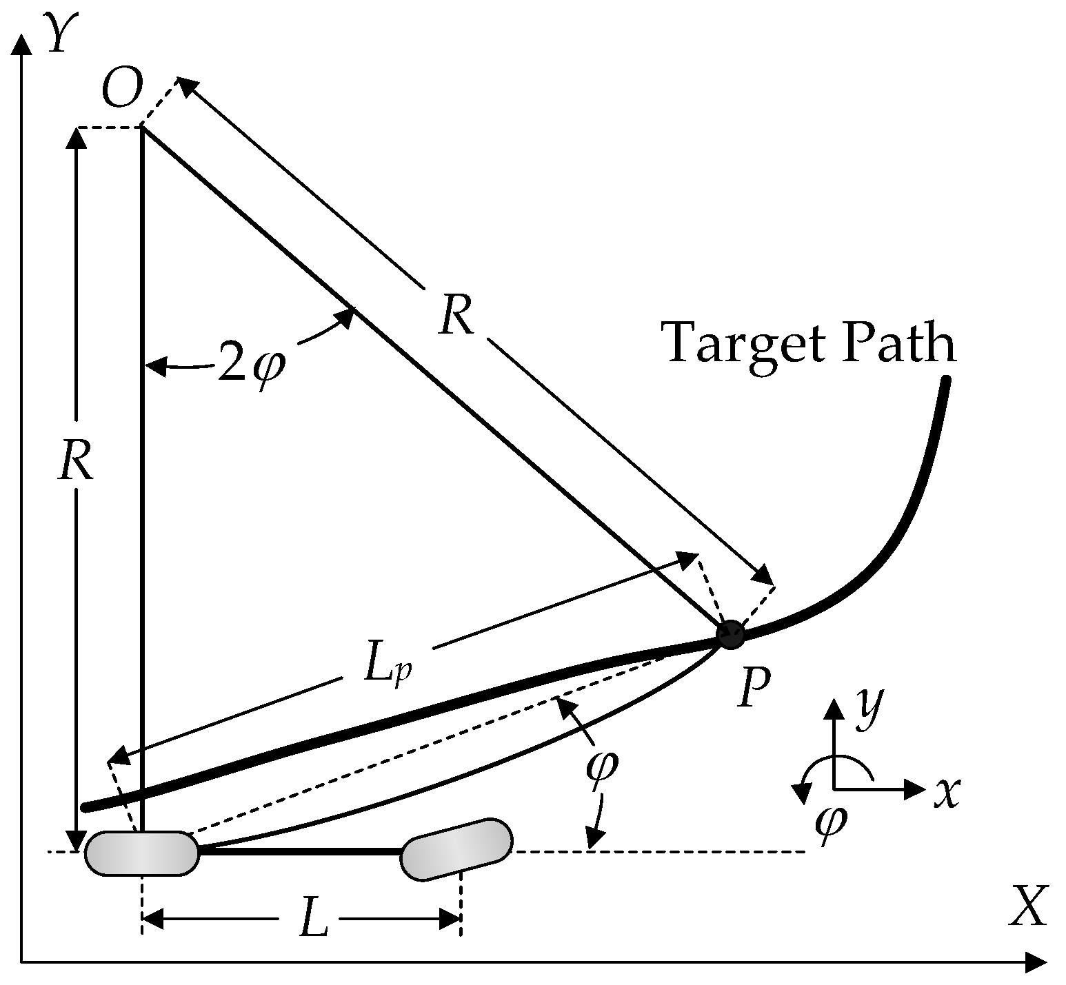
Figure 1. Pure pursuit geometry.
Machines 11 00403 g001
Figure 2. Target path and dynamic variables used for the Stanley method.
Machines 11 00403 g002
Figure 3. Coordinates and variables of 2-DOF dynamic bicycle model used for path tracking.
Machines 11 00403 g003
Figure 4. Measures for path tracking performance.
Machines 11 00403 g004
Figure 5. Simulation results of each controller for FWS vehicle on high-μ road obtained from the first set of simulations.
Machines 11 00403 g005aMachines 11 00403 g005b
Figure 6. Simulation results of each controller for FWS vehicle on low-μ road obtained from the second set of simulations.
Machines 11 00403 g006
Figure 7. Simulation results of each controller for 4WS vehicle on low-μ road obtained from the second set of simulations.
Machines 11 00403 g007aMachines 11 00403 g007b
Figure 8. Simulation results of each controller for FWS vehicle on low-μ road obtained from the third set of simulations.
Machines 11 00403 g008aMachines 11 00403 g008b
Figure 9. Simulation results of each controller for 4WS vehicle on low-μ road obtained from the third set of simulations.
Machines 11 00403 g009aMachines 11 00403 g009b
Figure 10. Simulation results of each controller for FWS vehicle on high-μ road obtained from the fourth set of simulations.
Machines 11 00403 g010aMachines 11 00403 g010b
Figure 11. Simulation results of each controller for 4WS vehicle on high-μ road obtained from the fourth set of simulations.
Machines 11 00403 g011aMachines 11 00403 g011b
Table 1. Parameter of F-segment sedan in CarSim.
ParameterValueParameterValue
ms1823 kglf1.27 m
Iz6286 kg⋅m2lr1.90 m
Cf42,000 N/radCr62,000 N/rad
Table 2. Summary of simulation results of each controller for FWS vehicle in the first set of simulations.
ΔX
(m)
ΔY
(m)
OS%ΔDX
(m)
ΔSX
(m)
MASSA
(deg)
MASSAR
(deg/s)
PPM0.01−0.0930.00.60−0.070.972.87
STM1.14−0.0160.22.491.840.943.38
PID0.08−0.0160.40.46−4.550.974.29
LQR0.53−0.0220.91.03−4.430.963.36
SMC0.41−0.0290.01.141.920.953.67
MPC0.45−0.0280.60.76−3.630.984.90
Table 3. Summary of simulation results of each controller for 4WS vehicle in the first set of simulations.
ΔX
(m)
ΔY
(m)
OS%ΔDX
(m)
ΔSX
(m)
MASSA
(deg)
MASSAR
(deg/s)
PPM0.03−0.0370.00.49−2.760.463.09
STM0.90−0.0240.22.100.220.391.84
PID0.150.0130.00.28−2.860.495.57
LQR0.48−0.0210.80.83−4.110.412.75
SMC0.08−0.0210.00.41−1.200.976.79
MPC0.43−0.0330.70.78−1.830.693.55
Table 4. Summary of simulation results of each controller for FWS vehicle in the second set of simulations.
ΔX
(m)
ΔY
(m)
OS%ΔDX
(m)
ΔSX
(m)
MASSA
(deg)
MASSAR
(deg/s)
PPM3.470.13639.210.0254.780.568.90
STM3.490.10919.79.9651.730.604.86
PID3.870.24128.511.0039.990.568.76
LQR4.180.21810.711.4632.330.556.49
SMC3.950.1860.017.1155.640.566.45
MPC4.230.23226.311.4441.270.5710.94
Table 5. Summary of simulation results of each controller for 4WS vehicle in the second set of simulations.
ΔX
(m)
ΔY
(m)
OS%ΔDX
(m)
ΔSX
(m)
MASSA
(deg)
MASSAR
(deg/s)
PPM91.970.47942.062.4955.9220.8617.78
STM90.304.51416.451.1154.4313.0719.13
PID4.880.42345.312.3555.9421.3717.80
LQR4.460.24010.011.4331.431.094.40
SMC3.650.20718.711.6955.3918.8132.01
MPC4.080.2060.012.4133.352.438.89
Table 6. Summary of simulation results of each controller for FWS vehicle in the third set of simulations.
ΔX
(m)
ΔY
(m)
OS%ΔDX
(m)
ΔSX
(m)
MASSA
(deg)
MASSAR
(deg/s)
PPM3.35−0.03112.79.5328.570.625.15
STM2.58−0.03512.28.7041.140.624.94
PID1.250.0311.98.6423.990.5911.71
LQR2.26−0.0450.09.0212.500.616.00
SMC2.910.0900.010.3610.980.587.39
MPC2.31−0.0450.29.3611.540.5910.89
Table 7. Summary of simulation results of each controller for 4WS vehicle in the third set of simulations.
ΔX
(m)
ΔY
(m)
OS%ΔDX
(m)
ΔSX
(m)
MASSA
(deg)
MASSAR
(deg/s)
PPM2.42−0.03214.37.7326.071.4116.51
STM2.33−0.0043.98.0617.870.8412.24
PID1.440.0340.88.635.481.2220.47
LQR2.46−0.0180.08.9411.710.934.09
SMC1.65−0.0081.48.5113.150.517.68
MPC2.560.0120.09.2413.233.678.22
Table 8. Summary of simulation results of each controller for FWS vehicle in the fourth set of simulations.
ΔX
(m)
ΔY
(m)
OS%ΔDX
(m)
ΔSX
(m)
MASSA
(deg)
MASSAR
(deg/s)
PPM0.83−0.1592.771.9416.330.973.00
STM0.60−0.1270.02.143.450.963.28
PID−1.77−0.1530.0−1.0512.141.075.71
LQR−0.11−0.1720.20.841.310.982.29
SMC−1.92−0.1000.00.382.601.013.93
MPC−0.01−0.1660.40.801.181.023.74
Table 9. Summary of simulation results of each controller for 4WS vehicle in the fourth set of simulations.
ΔX
(m)
ΔY
(m)
OS%ΔDX
(m)
ΔSX
(m)
MASSA
(deg)
MASSAR
(deg/s)
PPM1.05−0.0734.12.0716.470.372.13
STM2.020.0490.34.463.720.361.45
PID−1.61−0.1520.0−0.776.560.719.07
LQR−0.03−0.1510.30.810.620.372.56
SMC−1.15−0.1800.0−0.4515.310.914.17
MPC−0.12−0.1380.20.552.060.565.13
Disclaimer/Publisher’s Note: The statements, opinions and data contained in all publications are solely those of the individual author(s) and contributor(s) and not of MDPI and/or the editor(s). MDPI and/or the editor(s) disclaim responsibility for any injury to people or property resulting from any ideas, methods, instructions or products referred to in the content.