Abstract
The paper focuses on comparing applicability, tuning, and performance of different controllers implemented and tested on a finless rocket during its boost phase. The objective was to evaluate the advantages and disadvantages of each controller, such that the most appropriate one would then be developed and implemented in real-time in the finless rocket. The compared controllers were Linear Quadratic Regulator (LQR), Linear Quadratic Gaussian (LQG), and Proportional Integral Derivative (PID). To control the attitude of the rocket, emphasis is given to the Thrust Vector Control (TVC) component (sub-system) through the gimballing of the rocket engine. The launcher is commanded through the control input thrust gimbal angle , while the output parameter is expressed in terms of the pitch angle . After deriving a linearized state–space model, rocket stability is addressed before controller implementation and testing. The comparative study showed that both LQR and LQG track pitch angle changes rapidly, thus providing efficient closed-loop dynamic tracking. Tuning of the LQR controller, through the Q and R weighting matrices, illustrates how variations directly affect performance of the closed-loop system by varying the values of the feedback gain (K). The LQG controller provides a more realistic profile because, in general, not all variables are measurable and available for feedback. However, disturbances affecting the system are better handled and reduced with the PID controller, thus overcoming steady-state errors due to aerodynamic and model uncertainty. Overall controller performance is evaluated in terms of overshoot, settling and rise time, and steady-state error.
1. Introduction
Launchers and rockets are crucial assets for space exploration and other applications, such as meteorology, payload transportation, micro-gravity and high-g-force testing. The launcher and rocket configuration is based on the specific mission. High payloads require multiple propulsive stages, while reusable vehicles for Low Earth Orbit (LEO) missions are usually single-stage-to-orbit (SSTO) rockets. On the other hand, most rockets (i.e., sounding rockets) are generally finned, since fins act as passive stabilizers keeping the rocket on a relatively straight path (given an on board controller). While a rocket’s fins are an effective guidance system, they also increase the aerodynamic drag and rocket mass, which, in turn, affects the final orbital apogee reached with a given amount of propeller [1]. Modern launchers have a finless configuration, and they require an active control system to stably fly along the flight path.
This research focused on an analysis of the control system of a finless launcher during its ascent phase after take-off. A “time-slice” approach is followed to select constant launcher parameters during a frozen period along its trajectory [2,3,4]. Indeed, aerospace systems are, in general, both nonlinear and not time-invariant, and during the ascent phase the rocket exhibits highly nonlinear dynamics that result in variations of the flight parameters and of the inertial properties of the rocket. Thus, implementation and testing of different controllers are achieved via system linearization around a specific operating point. The rocket motion (in the pitch plane) is expressed through rigid-body analysis that considers slow changes in the physical properties of the rocket, such as mass and inertial properties, gimbal rotation of the engine and fuel sloshing. For controller implementation and testing, the TVC technique was considered, which results in an effective method for managing rocket attitude during flight through the gimbal angle .
The rest of the paper is organized as follows. Section 2 provides an overview of the TVC technique and discusses the common types of gimbal actuation. Section 3 discusses the rocket stability, showing the behavior of a finless rocket without active control. The model of the rocket is derived, along with the state space model, while the design requirements for the controller are provided in terms of overshoot, settling and rise time, and steady-state error. In Section 4, simulations and tests in a Matlab/Simulink environment illustrate the behavior of the flight plant’s dynamics when applying the three control approaches. Section 5 discusses obtained results and concludes the paper.
2. Thrust Vector Control
The Thrust Vector Control (TVC) actuation system is one of the common methods of managing the attitude of a rocket along its trajectory by acting on its propulsion system. This technique is effective when the propulsion system generates an exhaust plume from the nozzle, as is the case for rockets and jets. The TVC provides the control torques for both steering and stabilizing the rocket along the three main axes (roll, pitch, and yaw), overcoming disturbances of various natures. The disturbance torques affect the rocket attitude, resulting in an increase in fuel cost to maintain the right flight path. These phenomena are generally caused by wind gusts and aerodynamic forces acting on the launcher in different aerodynamic regimes, and by the fuel sloshing inside the tanks, as well as the relative motion between the gimballed engine mass and the fuselage mass, increasing the rocket instability. However, while the pitch and yaw control moments are achieved by only deflecting the thrust vector of the rocket, the roll control generally requires the use of two (or more) system nozzles, being the line of action-oriented parallel to the roll axis. This research centers around the pitch attitude control of the rocket through the gimbal of the main engine. Figure 1 shows an example of gimballed thruster systems.
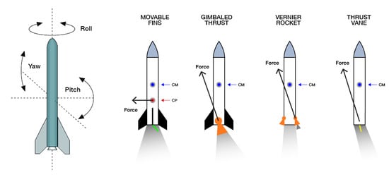
Figure 1.
Rocket main axes (left), TVC system along pitch direction (right). The gimbal action keeps as close as possible to 0, overcoming disturbance torques.
The thrust vectoring is not only used for changing the rocket attitude during powered flight, but it is also suitable for correcting both deviation from the expected trajectory and the misalignment of the thrust. As shown in Figure 1, the TVC with a single nozzle can be classified into four different categories, based on how the thrust vector is gimballed [5,6].
2.1. Mechanical Deflection of the Nozzle
The gimbal of the thrust is exploited by tilting the nozzle, or the entire engine (nozzle and combustion chamber), via a servo actuation system. The mechanical deflection generates the gimbal angle and, in turn, the control torques around the rocket’s center of mass, cm. The maximum gimbal angle allowed through the TVC system defines the so called cone of operation. Figure 2 shows the main types of joints used in the gimballing system of the engine.
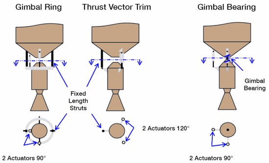
Figure 2.
Gimbal actuation system.
For small deflections of the engine (up to ), linear electromechanical actuators (EMA) can be used for pivoting the engine around the rocket main structure, thus rotating the thrust vector. Based on the low-/high-thrust applications and how the engine is deflected, different joints (bearings, rings and trim mechanisms) are used and driven by the actuators. A minimum of two actuators is required to have the full motion of the engine, while more than two are generally used for redundancy. Electrohydraulic actuators (EHA) are also used in common TVC systems to gimbal the engine during flight [7].
2.2. Exhaust Flow Deflection
This method involves placing aerodynamic wing-shaped surfaces, designed to be resistant to high temperatures and pressures, at the exit of the fix nozzle to orient the flow along the right direction. The advantage of the flow deflection is the ability of a single nozzle system to control the roll angle, rather than only pitch and yaw attitude. The main drawback is the progressive erosion of the vane material, and limited usage when the rocket flight speed increases, causing additional drag with larger vane deflections and a global reduction of the .
2.3. Injection of Secondary Propellant
The injection of a secondary fluid through the wall of the nozzle into the main flow stream causes the formation of oblique shock waves in the nozzle diverging section, causing an unsymmetrical distribution of the exhausted plume that, in turn, changes the direction of the main thrust vector. The injector is mounted on the rocket’s main engine and the fluid is then injected into one side of the flow. Dense reactive fluids are preferred, and the system works well for small deflection of the flow, while for large gimbal moments, the amount of secondary propellant needed becomes excessive.
2.4. Auxiliary Verner Thrusters
This technique consists of using auxiliary thrust chambers to provide roll control during the operational phases of the principal engine. The vernier thrusters are small engines used on rockets and heavy spacecraft to make adjustments to the attitude and velocity. The secondary chambers are fed by the rocket’s main engine feed system.
3. Rocket Stability
From the stability point of view, rockets are divided into two main categories: finned rockets and finless rockets [1]. Their flight dynamic is directly influenced by the fins, since during the flight phases the drag in the rear of the fuselage increases, causing the rocket’s center of pressure cp to move behind the rocket’s center of gravity cg (Figure 3) and, in turn, to correct both the angle of attack , defined in the yaw-roll plane as the angle between the rocket flight direction and the rocket longitudinal axis, and the sideslip angle , the corresponding angle in the pitch–roll plane.
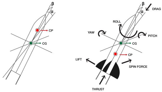
Figure 3.
Stability of rockets: unstable finless rocket (left) and stable finned rocket (right).
Fins act as a passive guidance system, allowing the rocket to orient and be more stable during flight. As a main drawback, fins increase both the rocket mass and the fluttering phenomena at high speed flight. In contrast, finless rockets are unstable by nature because of the inverted position of the cp and the cg, with the cp well ahead of the cg. Moreover, the fuel reduction during the propelled phases causes the cg to move back further, leading to an increase of both the deviation angles and and the aerodynamic disturbance torques, increasing the instability of the rocket. For these reasons, active guidance control is crucial to counteract the drag force in a finless rocket.
3.1. Flight Dynamic Assumption for Controller Design
During the ascent phase, the rocket exhibits highly non-linear dynamics resulting in a variation of the flight parameters and the inertial properties of the launcher [8]. For this reason, aerospace systems are generally nonlinear and time-variant systems. For design and analysis purposes related to the rocket’s control system in the pitch plane, different assumptions are made:
- Rigid body motion to describe the launcher system;
- Short-period flight dynamic, with small angle deviations from the reference trajectory;
- Linearization of the dynamics of the rocket plant obtained by time-invariant equations over a short-time period around a specific operating point and after the take-off phase;
- Linear-Time-Invariant (LTI) approach in the launcher design, assuming both mass and inertial properties of the launcher change slowly during the flight (no sloshing phenomena are considered).
3.2. Rocket Model
A simplified model of a finless launcher was adopted (Figure 4), [2]. The reported values were derived from the rocket reference trajectory [4], assuming the operating point was at altitude h = 10 Km, 60 s after take-off, and Mach number M = 1.4 (Table 1). Both the inertial reference frame (X, Y, Z) and the body-fixed axes (x, y, z) are centered around the rocket cg. is the pitch moment of inertia; is the gimballed control thrust, while is the ungimballed thrust aligned to the body axis x; F = + is the total thrust force; V is the vehicle velocity, the aerodynamic force and , the aerodynamic derivatives that are expressed as
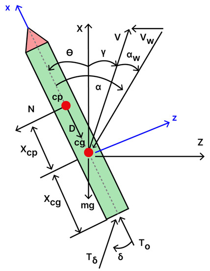
Figure 4.
Simplified model of the finless launcher.

Table 1.
Launcher parameters at operation point t = 60 s.
is the known input gimbal angle, = + + is the effective angle of attack, with the pitch angle and = being the flight path drift angle. The acting aerodynamic forces are the drag , the lift force N applied at the cp, the inertial drift velocity and the wind disturbance velocity, according to the wind-induced angle of attack ( = /V).
The drift velocity caused by the wind is added to the velocity along the Z-axis acting during the ascent phase, leading to a lateral motion of the rocket and a consequent deviation from its nominal trajectory. To guarantee effective control after take-off, the controller needs to adjust the position of the launcher acting against the wind to maintain a drift rate as close to as possible. Starting from the rocket dynamic, the equations of motion linearized at the operating point with small angular deflections are given by:
Combining Equations (2)–(4), the resulting state–space model is:
Equation (6) is the output vector, with the pitch angle as the single measured output; the feed-forward matrix D is 0 since the system input does not directly affect the system output. The actuator deflection is the input of the system together with . The wind-induced angle of attack is the system’s unknown input, and it has to be estimated.
3.3. Stability Analysis
As described above, finless rockets are inherently unstable, and, thus, they require attitude stabilization. The unstable behavior is demonstrated considering the flight dynamics of the rocket along its trajectory without active control of the plant (Figure 5).
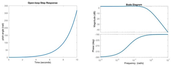
Figure 5.
Open−loop response (left), bode plots (right).
The measured output increases progressively with time causing a strong deviation of the rocket from its nominal path, suggesting the instability of the plant when the system is perturbed with the input gimbal angle. Looking at the eigenvalues of the plant further validates the rocket instability because of the one negative real root:
Another method used to obtain a measurement of the stability of the system is based on the analysis of the bode plots of the open−loop transfer function. As shown in Figure 5, the gain margin is negative, as well as the phase margin, confirming the system is unstable. For effective control of the launcher, the control capability of the thrust vector must counteract the aerodynamic loads acting on the launcher, given by: > . The control moment of the thrust must be larger than the aerodynamic moment, dealing with a maximum allowable gimbal angle () of the TVC actuator. Besides this, the maximum admissible angle of attack has an impact on the flight conditions, limiting the launch windows in which the rocket can safely fly through its trajectory without encountering irreversibly unstable dynamics.
3.4. Controller Design
The implementation of the TVC system is given by the command signals forwarded to the servo actuation system through the autopilot. Indeed, the autopilot performs precise nozzle deflection by commanding the rocket actuators and, in turn, the gimbal of the nozzle. The actuators’ gimballing generates the pitch moment and torque around the rocket cg, allowing for the control of both rocket attitude () and angular velocity (). The deflection of the nozzle is generally measured by position sensors and its measurement is available as a feedback signal. The rocket considered in this study is equipped with a single motor, so the thrust vectoring allows the control of the motion in the pitch–yaw angle without any effect on the roll motion. The analysis considers the pitch angle as the only measured system output.
The design requirements for the implementation of the controller [9] are the following:
- Overshoot < 10%
- Settling time < 10 s
- Rise time < 2 s
- Steady-state error < 2%
4. Simulations and Results
This section introduces the control architectures for the LQR and LQG controllers. Simulations were executed using Matlab and Simulink tools.
4.1. LQR Simulation: System Analysis and Model Implementation
The main objective of the LQR control logic is to optimally select the feedback gain K that minimizes the performance index J [10,11,12]. The design conditions in 3.4 are the driving requirements for the implementation of the controller.
The controllability of the system is a necessary condition for the implementation of the LQR control logic [13] since this property deals with the system stabilization when using the optimal control theory. Thus, the analysis starts with the requirement of the system controllability matrix
Since Co is a full-rank matrix, the number of uncontrollable states is 0, hence the rocket is controllable. Then, the weighting matrices Q and R are selected using an initial trial and error approach, together with the Anderson approximation, obtaining Q = and R = 1.1. Through the Matlab lqr function, the computed feedback gain associated with the rocket system is
For simulation studies, the tracking pitch angle was set to 0.06 rad (gimbal angle should not exceed , Section 2.1) starting from an initial condition of
The resulting trends (Figure 6) clearly show that the LQR had an appreciable response in terms of plant stabilization and optimization of the output state . The TVC system was able to correct the rocket position through the gimbal angle . From the resulting behavior, the pitch rate stabilized at the tracked attitude and the controller satisfied the design requirements, having its parameters included well in the range values Table 2.
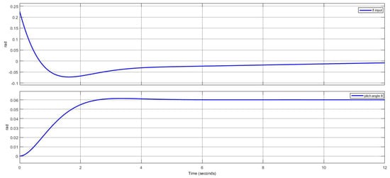
Figure 6.
LQR response.

Table 2.
LQR controller performances.
4.2. LQR Tuning
The results obtained by the LQR simulation met the controller requirements. However, not only the results affect the behavior of the rocket dynamics. Indeed, the tuning of Q and R directly impacts the controller performance, since both the matrices influence the feedback gain K. When a first iteration of the gain does not meet the required plant specifications, varying R and Q allows for a change in the plant response, becoming slower or faster based on the value of the re-tuned K. Thus, the tuning of the weighting matrices [14,15,16,17] allows to maximize the controller performance in order to meet the plant’s requirement. Since the weighting matrices Q and R have corresponding effects on K, to obtain the right values of the gain some criteria can be followed, as summarized below:
The tuning principle reported in Table 3 shows a logical guideline for correctly tuning the LQR controller. To demonstrate the impact that Q and R have on the system dynamics, two different simulations were conducted by varying their weights, while the operative point and the characteristics of the rocket system remained unchanged.

Table 3.
Weighting matrices tuning principle.
4.2.1. Tuning 1: R Varied, Q Unchanged
In this simulation the matrix Q was maintained as Q = , while the values of the R matrix varied from R = 1.1 to = 0.1, = 2.1. The resulting gains associated to the varied matrices are reported in Table 4. Figure 7 shows the results obtained. The response curves were reported and compared to the curve (blue line) previously obtained.

Table 4.
LQR simulation Q, R tuning.
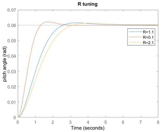
Figure 7.
R variation and response.
It was observed that K decreased when tuning R at higher values. The reduction of the gain dealt with a slower change in the state variables. Moreover, the estimated response of the controller became slower as its settling time was longer. A different behavior was observed when tuning R at a lower value. The gain K increased, and the state variables change closed to zero faster, dealing with a higher response of the controller as the settling time became shorter.
4.2.2. Tuning 1: Q Varied, R Unchanged
Similarly to the previous simulation, the value of R remained unchanged, and the weighting factor of Q varied from p = 15 to = 5, = 25. The system response is reported in Figure 8 and compared to the curve (blue line) previously obtained.
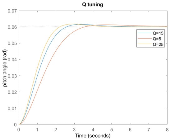
Figure 8.
Q variation and response.
When tuning Q, the variation of K was directly proportional. For higher values of Q the gain increased, together with the response of the plant’s state becoming faster, and the response of the controller became faster because of its shorter settling time. On the other hand, a reduction of Q meant the gain dealt with a slower change in the plant’s state, and the response of the controller reduced. From the results obtained by tuning R, it can be noticed that the smaller the magnitude of R, the smaller the curve error tracked. However, a significant reduction in the magnitude of R strongly impacted the controller’s performance. When tuning Q, the tracking of the error became smaller, since the deviation for was closer to zero. This, in turn, would require a higher control effort which entails an increase in the required thrust control force and, therefore, in the actuator sizing.
4.3. LQG Simulation
The LQG control addresses the fall of the LQR assumption for which all the states of the system are available for feedback [18,19]. In the LQG logic, the required states of the system are estimated through the Kalman filter and, then, through the estimated states, the LQR controller is designed. The LQG control combines the LQR feedback gain and the Kalman estimator in order to have, as output, instead of the full state of the system. Since the LQR block requires the full state to compute the control loop, the full-order observer (Kalman filter) takes, as inputs, u and to represent the estimation of x, having the form
The equation in (11) has two inputs: the process control input u and its sensors’ measured output y. In the simulation, the reference pitch angle remained = 0.06 rad, but now the full-order observer estimates the system variables, and, thus, the rocket model must also be observable. The observable matrix of the system is
The system is completely observable since it does not have uncontrollable states (length of the A matrix = rank(Ob)), allowing for the implementation of the LQG control logic [20]. To reproduce a real scenario, the process noise and the measurement noise were added to the system in the form of the covariance matrices , . The computed Kalman gain matrix was = [5.0631, 4.4843, −21.7718], while the system response is given in Figure 9.
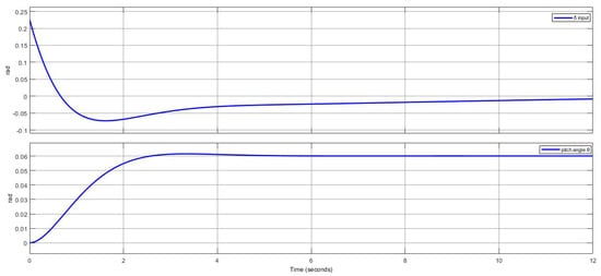
Figure 9.
Tracking of with LQG controller.
The LQG controller showed almost the same response as the LQR, since the Kalman filter correctly estimated the states of the system, while the optimal feedback gain stabilized the rocket, tracking to the commanded reference value.
4.4. PID Simulation
The third controller involves the PID criteria. This control logic acts through three gains, each with a specific action mode but with a correlated loop response [21,22,23,24]. As a starting point, the rocket system is analyzed with the PID action. The transfer function G associated to the launcher system is
The PID gains are derived in Table 5 following both an initial iterative tuning and the Ziegler–Nichols formula [25].

Table 5.
PID gain tuning.
In Figure 10, the simulated results show the stability of the system after an initial overshoot, reaching the zero steady−state error within the design rise time (0.2193 s), while the overshoot slightly exceeded 10% (13.82%). In order to fulfill the controller requirements, a multiple tuning approach allows better performance of the position tracking, showing how the PID gains impact the controller response, (Figure 11), while the corresponding tuned values are given in Table 6. The gains , , were obtained with an initial trial and error tuning followed by the Ziegler–Nichols method.
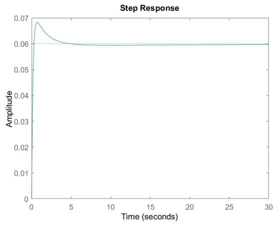
Figure 10.
PID response.
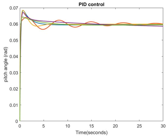
Figure 11.
PID gain tuning.

Table 6.
PID gain re-tuning.
Table 7 summarizes the different performances of the PID controller. The fifth tuning () satisfied the design requirements.

Table 7.
PID controller performances.
4.5. System Robustness: Precompensator and PID Comparison
The LQR control is able to track the rocket attitude by correctly tracking the pitch angle through the TVC input system. To scale the tracking reference value, a precompensator was added to the model, allowing the system to reach the commanded reference signal. Figure 6 shows the behavior of and the successful tracking of the steady-state error, close to 0. However, when disturbance phenomena acted outside the precompensation loop, or the model had some uncertainties, the error started to diverge and the control logic was no longer able to maintain the controller within the design requirements. To investigate this phenomenon, a gust disturbance was added to the system and modeled as a step signal (Figure 12).
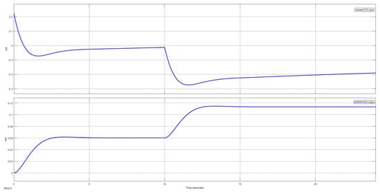
Figure 12.
response with disturbance out of precompensation feedback−loop.
The pitch angle was initially tracked correctly, reaching the desired value, but when the system disturbance occurred at t = 15 s, it drove the system away from the desired steady-state value of 0.06 rad, even with the presence of the precompensator, as the precompensation loop was no longer able to correct the disturbance deviation. The same simulation was run with the PID control loop, and the controller response is shown in Figure 13.
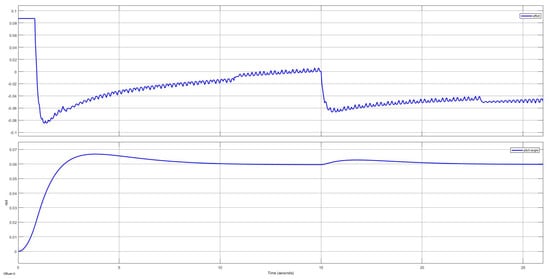
Figure 13.
Tracking of with PID controller.
As a robust technique, the PID control overcame the steady−state error that arose due to disturbances and model uncertainties thanks to its integral action. As shown in Figure 13, the implemented controller correctly tracked the pitch response at the desired value. The controller was designed with ±0.0872 rad of saturation limit.
5. Discussion
Based on the obtained results, it was shown that the LQR, LQG and the PID controllers satisfied set control requirements (Section 3.4), although their performances varied, based on the implemented control logic. Optimal LQ controllers have similar behavior. This was verified, as LQG exhibited a stable response and its performance was similar/close to the LQR (where a Kalman filter is used for system state estimation).
When comparing Table 2 and Table 7, it is observed that LQR performed better than PID in terms of overshoot, settling time, and steady-state error, allowing for a faster track of the reference angle. On the other hand, the PID integral action allowed for the controller to correctly manage the disturbances acting on the launcher, even outside the precompensation loop. The gain tuning process shows how the Q and R matrix variation and changes in , and directly affected controller performance. In particular, Table 6 shows how PID was more subjected to gain parameter variations, requiring a major effort to satisfy design requirements when compared to the LQR tuning performance.
In summary, this comparative study offers valuable information when it comes to deciding which controller is to be developed and implemented in real-time on board a finless rocket.
Author Contributions
Conceptualization, L.S., K.P.V., M.S. and P.L.; methodology, L.S.; validation, L.S., K.P.V., M.S. and P.L.; formal analysis, L.S.; investigation, L.S.; resources, K.P.V. and P.L.; data curation, L.S.; writing—original draft preparation, L.S.; writing—review and editing, K.P.V., M.S. and P.L.; supervision, K.P.V., M.S. and P.L.; project administration, K.P.V. and P.L. All authors have read and agreed to the published version of the manuscript.
Funding
This research received no external funding.
Data Availability Statement
Not applicable.
Conflicts of Interest
The authors declare no conflict of interest.
Abbreviations
The following abbreviations are used in this manuscript:
| TVC | Thrust Vector Control |
| LQR | Linear Quadratic Regulator |
| LQG | Linear Quadratic Gaussian |
| PID | Proportional, Integral, Derivative |
| LEO | Low Earth Orbit |
| SSTO | Single-stage-to-orbit |
| EMA | Electro-mechanical actuator |
| EHA | Electro-hydraulic actuator |
| LTI | Linear Time Invariant |
| SISO | Single Input Single Output |
| MIMO | Multi Input Multi Output |
| Specific Impulse |
References
- Gomez, F.J.; Miikkulainen, R. Active guidance for a finless rocket using neuroevolution. In Genetic and Evolutionary Computation Conference; Springer: Berlin/Heidelberg, Germany, 2003; pp. 2084–2095. [Google Scholar]
- Sopegno, L.; Livreri, P.; Stefanovic, M.; Valavanis, K.P. Linear Quadratic Regulator: A Simple Thrust Vector Control System for Rockets. In Proceedings of the 2022 30th Mediterranean Conference on Control and Automation (MED), Athens, Greece, 28 June–1 July 2022; pp. 591–597. [Google Scholar]
- Meirovitch, L. General motion of a variable-mass flexible rocket with internal flow. J. Spacecr. Rocket. 1970, 7, 186–195. [Google Scholar] [CrossRef]
- Du, W. Dynamic Modeling and Ascent Flight Control of Ares-I Crew Launch Vehicle; Iowa State University: Ames, IA, USA, 2010. [Google Scholar]
- Bernacchia, D. Design of Thrust Vectoring Attitude Control System for Lunar Lander Flying Testbed Rocket Stability. Ph.D. Thesis, Università di Bologna, Bologna, Italy, 2018. [Google Scholar]
- Suchitra, P.; Kurian, P.C.; Jones, S.R. Optimal controller based servo system design for the thrust vector control of liquid propellant engine of three-stage launch vehicle. In Proceedings of the 2014 Annual International Conference on Emerging Research Areas: Magnetics, Machines and Drives (AICERA/iCMMD), Kottayam, India, 24–26 July 2014; pp. 1–6. [Google Scholar]
- Lazić, D.V.; Ristanović, M.R. Electrohydraulic thrust vector control of twin rocket engines with position feedback via angular transducers. Control Eng. Pract. 2007, 15, 583–594. [Google Scholar] [CrossRef]
- Wie, B.; Du, W.; Whorton, M. Analysis and design of launch vehicle flight control systems. In Proceedings of the AIAA Guidance, Navigation and Control Conference and Exhibit, Honolulu, HI, USA, 18–21 August 2008; p. 6291. [Google Scholar]
- Kisabo, A.B.; Osheku, C.A.; Adetoro, M.; Funmilayo, A. Fuzzy Logic Control for an Expendable Launch Vehicle Autopilot. Eur. J. Sci. Res. 2011, 59, 226–240. [Google Scholar]
- Duriez, T.; Brunton, S.L.; Noack, B.R. Machine Learning Control-Taming Nonlinear Dynamics and Turbulence; Springer: Berlin/Heidelberg, Germany, 2017; Volume 116. [Google Scholar]
- Anderson, B.D.; Moore, J.B. Optimal Control: Linear Quadratic Methods; Courier Corporation: Chelmsford, MA, USA, 2007. [Google Scholar]
- Lutambo, J.; Wang, J. Turbofan engine modelling and control design using linear quadratic regulator (LQR). Int. J. Eng. Sci. 2017, 6, 49–58. [Google Scholar] [CrossRef]
- Agbaraji, E.C.; Akwu, A. Investigation on Controllability, Observability and Stability for Plant Optimal Control Performance. Eur. J. Eng. Technol. 2016, 4, 40–47. [Google Scholar]
- Murray, R.M. Optimization-Based Control; California Institute of Technology: Pasadena, CA, USA, 2009; pp. 111–128. [Google Scholar]
- Kisabo, A.B.; Adebimpe, A.F.; Samuel, S.O. Pitch control of a rocket with a novel LQG/LTR control algorithm. J. Aircr. Spacecr. Technol. 2019, 3, 24–37. [Google Scholar] [CrossRef]
- Ghoreishi, S.A.; Nekoui, M.A. Optimal weighting matrices design for LQR controller based on genetic algorithm and PSO. Adv. Mater. Res. 2012, 433, 7546–7553. [Google Scholar] [CrossRef]
- Okyere, E.; Bousbaine, A.; Poyi, G.T.; Joseph, A.K.; Andrade, J.M. LQR controller design for quad-rotor helicopters. J. Eng. 2019, 2019, 4003–4007. [Google Scholar] [CrossRef]
- Hespanha, J.P. Lecture notes on lqr/lqg controller design. Knowl. Creat. Diffus. Util. 2005, 1, 1–52. [Google Scholar]
- Mohammed, U.; Karataev, T.; Oshiga, O.O.; Hussein, S.U.; Thomas, S. Comparison of Linear Quadratic–Regulator and Gaussian–Controllers’ Performance, LQR and LQG: Ball-on-Sphere System as a Case Study. Int. J. Eng. Manuf. (IJEM) 2021, 11, 45–67. [Google Scholar] [CrossRef]
- Duy, D.A.; Le Hoai Phuong, V.D.C. Stability Analysis and Assessment of Double Inverted Pendulum with LQR and LQG Controllers. J. Mech. Eng. Res. Dev. 2021, 44, 408–417. [Google Scholar]
- Mojumder, M.R.H.; Roy, N.K. PID, LQR, and LQG Controllers to Maintain the Stability of an AVR System at Varied Model Parameters. In Proceedings of the 2021 5th International Conference on Electrical Engineering and Information and Communication Technology (ICEEICT), Dhaka, Bangladesh, 18–20 November 2021; pp. 1–6. [Google Scholar]
- Wael, M.A.; Quan, Q. Robust hybrid control for ballistic missile longitudinal autopilot. Chin. J. Aeronaut. 2011, 24, 777–788. [Google Scholar] [CrossRef]
- Lee, C.L.; Peng, C.C. Analytic Time Domain Specifications PID Controller Design for a Class of 2nd Order Linear Systems: A Genetic Algorithm Method. IEEE Access 2021, 9, 99266–99275. [Google Scholar] [CrossRef]
- Kisabo, A.B. Expendable Launch Vehicle Flight Control: Design & Simulation Matlab/Simulink; Saint-Petersburg State University of Aerospace Instrumentation: Saint Petersburg, Russia, 2011; pp. 1–119. [Google Scholar]
- Alandoli, E.; Rashid, M.; Sulaiman, M. A Comparison of PID and LQR Controllers for Position Tracking and Vibration Suppression of Flexible Link Manipulator. J. Theor. Appl. Inf. Technol. 2017, 95, 2949–2955. [Google Scholar]
Disclaimer/Publisher’s Note: The statements, opinions and data contained in all publications are solely those of the individual author(s) and contributor(s) and not of MDPI and/or the editor(s). MDPI and/or the editor(s) disclaim responsibility for any injury to people or property resulting from any ideas, methods, instructions or products referred to in the content. |
© 2023 by the authors. Licensee MDPI, Basel, Switzerland. This article is an open access article distributed under the terms and conditions of the Creative Commons Attribution (CC BY) license (https://creativecommons.org/licenses/by/4.0/).