Abstract
Aiming to solve the problems of poor dynamic response characteristics and the weak anti-jamming capability of the conventional proportional–integral–derivative (PID) controlled pump-motor servo system (PMSS) under the actual working environment, this study created a brand new hybrid grey wolf optimization (GWO) and particle swarm optimization (PSO) algorithm to determine the best parameters of the PID controller for the PMSS speed control to make the PMSS achieve a constant speed control. We developed a GWOPSO-PID controller and compared it with a conventional PID controller, GWO-PID, PSO-PID, and GA-PID. In comparison to the other four control methods, the simulation and experimental results demonstrate that the designed GWOPSO-PID control had better dynamic response characteristics, with its rise times being reduced by 78.6%, 64.7%, 67.1%, and 41.5%, respectively. Additionally, the system under the GWOPSO-PID control exhibits a good stability and robustness even in the face of different load circumstances, with decreases in the re-equilibration times of 59.6%, 23.4%, 53.2%, and 41.9%, respectively, with a significantly improved immunity to disturbances.
1. Introduction
The hydraulic servo system has developed into one of the leading research goals in hydraulic control as a high-precision feedback control technology [1]. Pump–motor servo systems (PMSSs) as an integral component of electro-hydraulic servo systems (EHSSs), are extensively applied in the manufacturing industry due to their excellent efficiency, sizable load capacity, and high power-to-weight ratio [2]. Controlling the motor’s speed is one of the fundamental difficulties in hydraulic servo systems. The most common controllers used in hydraulic servo systems are still PID ones [3]. They have a straightforward construction, dependable operation, and strong performance. The sensitivity of the conventional PID control to the parameter changes is high [4]. The controlled impact will be greatly diminished whenever the control environment changes, making it difficult to effectively achieve a consistent speed control of the motor.
Researchers from all around the world are currently focusing on the EHSS control system. Numerous control methods were suggested to increase the consistency and robustness of the EHSS control, such as adaptive logic [5], deep neural networks [6], hybrid algorithms optimization [7], and other artificial intelligence techniques to boost the control accuracy of the EHSS. Samakwong et al. considered an optimization technique using a GA to tune the PID controller parameters of an EHSS [8]. According to the results, the GA optimized controller has a 60.6%, 46.1%, and 37.4% reduction in the response time compared to Ziegler–Nichols, the automated tuning technique, and PSO, respectively. Wu et al. proposed an intelligent water drop (IWD) algorithm that utilizes a two-stage mass equilibrium and multi-objective optimization to boost the rationality of hydraulic loading control development [9]. For the central position control of the rolling strip, Jia L. et al. applied a modified PSO optimized integral separation PID approach, resulting in a system with a minimum position overshoot of 3%, which is far better than other control strategies [10]. Fadel et al. adopted a method of selecting suitable PID controller parameters by GA to improve the transient response characteristics of a non-linear EHSS; the average percent overshoot reduction is about 83% and the settling time reduction is about 50% [11]. Zheng et al. designed a sliding mode controller based on a quantum particle swarm optimization (QPSO) algorithm to improve the anti-interference ability of an EHSS, which led to an increase in the tracking accuracy of 36.8% [12]. Furthermore, Wang et al. considered an enhanced artificial bee colony (EABC) approach to achieve the optimization of the steel strip deviation PID control system (SSDCS), with a 27.6% reduction in the system overshoot compared to the basic artificial bee colony (BABC) algorithm [13].
For the problem of a local minimum stagnation in the traditional heuristic algorithms mentioned above, researchers have successively proposed improvement strategies such as hybrid optimization algorithms. Patel et al. created an artificial neuro-fuzzy logic PID controller that used a hybrid method of bacterial foraging (BF) and PSO, outperforming traditional controllers in the process [14]. Ye et al. mixed PSO and GA to determine the optimal PID controller gain for an excavator valve-controlled cylinder system, which reduced the rising time and settling time by 19.5% and 27.8%, respectively [15]. Le Dinh and Temkin showed how to apply a hybrid BFPSO and adaptive PSO to obtain the PIDs appropriate parameters, which leads to the PMSMs stable speed control [16]. As in the investigation of Fan Y et al., the modelling and simulation of a force actuator system using the self-growing Lévy-flight salp swarm algorithm (SG-LSSA) as an optimized PID controller is given [17].
In addition, a lot of scholars are concerned about the existence of a load interference in the EHSS. Chen et al. developed a novel control strategy for velocity servo systems based on deep reinforcement learning that achieves automatic PID tuning and effectively overcomes the effects of inertial surges and torque disturbances [18]. Çelik and Gör developed a PI + DF high-performance controller with optimized parameters using a stochastic fractal search (SFS) technique, which demonstrates the most precise speed response in complicated circumstances [19]. Yu et al. have developed a force control method combining tracking error compensation and load compensation control, which can improve the control accuracy of a pump-valve composite drive system (PCDS) by approximately 49% and improve the tracking accuracy by over 68% compared to PID [20]. Wang et al. proposed an improved active disturbance rejection control (ADRC) technique based on the GWO, thus meeting the accuracy requirements of continuously rotating motors under uncertain and strong disturbance factors [21]. Another study applied a load force compensated fuzzy PID control algorithm based on an improved PSO to the adaptive control of valve-controlled asymmetric hydraulic cylinder positions [22]. However, the above work does not sufficiently consider the case of load disturbances.
Meanwhile, Yuan H B et al. presented an electro-hydraulic position tracking and recognition system based on PI + MPC hybrid control [23]. Essa et al. illustrated the cuckoo search algorithm (CSA) and GA optimized the parameters of the model predictive control (MPC) to realize the force tracking control of the EHSS [24]. Feng et al. improved the PSO-PID controller using an asynchronous variation strategy, which can improve the trajectory tracking accuracy of the EHSS by up to 37.14% and 50.32%, respectively, compared to the basic PSO-PID control method [25]. Feng et al. used RBF neural networks to improve the adaptive sliding mode control method (SMC-RBF) to achieve the trajectory tracking of the EHSS. The experimental results show that the SMC-RBF controller reduces the average tracking error by 42.42% compared to the SMC controller [26]. He Z et al. introduced an electro-hydraulic position servo system based on the synovial proactive disruption avoidance composite control method [27]. It can be seen that more effort has been put into force control systems and position control systems and less into speed control systems.
The aforementioned literature reveals that several researchers have examined the EHSS control technique from various angles. Table 1 details the research gaps that exist in the main work that has now been published. Fine-tuning the PID controller’s settings using a heuristic optimization approach is a highly efficient way to enhance the response properties of the EHSS. However, due to the high non-linearity of the PMSS, its internal control chain has a strong coupling relationship. Although traditional heuristic optimization algorithms (such as GWO, PSO, GA, etc.) show great potential to solve PID optimization problems, they still suffer from the defects of memory capacity and computational burden [28]. The complicated and variable operating circumstances of the PMSS in real applications place great demands on the system’s control performance. The resilience of the PID controller that has been the optimized heuristic algorithm has to be increased although it has a high tracking and steady performance. The study of an effective and practical PID parameter tuning technology for researchers is crucial since the development of control technology is on the horizon. Combining heuristic optimization algorithms has been a common way to enhance algorithms in recent years, according to the peculiarities of specific algorithms [29]. Based on the aforementioned motives, this work suggests a brand-new technique called GWOPSO, which combines the GWO and PSO algorithms to optimize the PID controller in the PMSS and enhance the system’s dynamic response properties. The goal of this work is to employ a solution that is straightforward and inexpensive to apply to tackle the speed control issue for the PMSS. From the standpoint of an engineering application, this work is significant and it is hoped that it will be adopted and used in the area of electro-hydraulic servo control.

Table 1.
The summary of research gaps in published primary work.
Because of the challenges in identifying the parameters of the existing conventional controller and the poor dynamic response characteristics of the PMSS, a split new GWOPSO optimized available controller is developed to realize the speed control of the PMSS in this paper. The followings might be used to describe the key contributions of this research article:
- (a)
- To overcome the issues of the sluggish convergence and low accuracy of existing heuristic optimization algorithms, a new PSO and GWO combination known as GWOPSO is developed.
- (b)
- The presented GWOPSO method is used for eight benchmark test problems and the findings demonstrate that in terms of the calculation time and optimization correctness, the GWOPSO outperforms the GWO, the PSO, the GA, and other comparable strategies.
- (c)
- Because the PMSS is a high-order non-linear time-varying system, it is challenging to achieve a decent control effect when relying on the current control strategies. In this study, we create a brand-new GWOPSO-PID controller and apply it to regulate the PMSS.
- (d)
- Most of the existing studies have always been conducted in the ideal status of the PMSS, ignoring the influences brought by load variations on the system’s performance. The effectiveness of the GWOPSO-PID controller is evaluated by simulation and contrasted with that of the conventional PID controller, GWO-PID controller, PSO-PID controller, and GA-PID controller under various load situations by using the same ITAE objective function.
- (e)
- Experimental validation by a hardware implementation of an industrial PMSS. The dynamic response characteristics of the GWOPSO-PID controller under different load circumstances are confirmed by analysis and the robustness and viability of the GWOPSO-PID controller are confirmed.
2. Problem Formulation
The explanation of the PMSSs operating system and the creation of the mathematical model are covered in this part. As a consequence, it is split into the following three portions.
2.1. System Description
Figure 1 shows the schematic diagram of the PMSS. The constant pressure variable pump is selected as the power element by the PMSS in this study. During operation, the variable pump supplies oil to the variable motor and pushes it to rotate to move the burden. The current control loop is shown by the blue circuit in Figure 1. The system continually measures the motor speed through the speed sensor in the control link and sends the gathered electrical signal in the form of a current to the A/D converter. The A/D converter transforms the analogue quantity into a digital quantity and provides it to the controller. The controller adjusts the opening size of the electro-hydraulic servo valve by the difference between the set speed and the actual speed to complete the control of the hydraulic cylinder piston rod expansion and contraction. The hydraulic cylinder is a variable hydraulic cylinder. The cylinder rod solely on a single side is used to control the variable motor’s swash plate swing angle to control the motor’s speed. The piston rod on the other side is equipped with a displacement sensor, which tracks the telescopic displacement of the piston rod in real-time and feeds that information back. In summary, the PMSS consists of two components: the valve controlled hydraulic cylinder link and the pump–motor coupling scheme that drives the load. It is well recognized that explaining the PMSS has the goal of laying the groundwork for the development of effective speed control measures for the PMSS. The operating parameters of the key components of the PMSS are shown in Table 2.
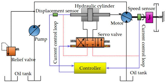
Figure 1.
Schematic diagram of PMSS.

Table 2.
Key components of PMSS operating parameters.
2.2. Valve-Controlled Hydraulic Cylinder Model
The electro-hydraulic servo valve is typically considered to be a two-stage order oscillation connection and its transfer function is as follows in Equation (1) [30]:
where Qv(s) is the output flow of the servo valve; Uv(s) is the input voltage of the servo valve; Ev is the flow gain of the servo valve; ωv is the natural frequency of the servo valve; and ξv is the damping ratio of the servo valve.
The internal and exterior leaks of the hydraulic cylinder, as well as the pipeline pressure loss and dynamic properties, are disregarded [31]. The flow continuity formula of the hydraulic cylinder is:
where qv is the input flow rate of the hydraulic cylinder (equal to the output flow rate of the servo valve); Ap is the effective area of the hydraulic cylinder piston; xp is the piston displacement; βe is the equivalent bulk elastic modulus (including the oil, connecting pipes, and the mechanical flexibility of the cylinders); Vt is the total compression volume; Ctp is the total leakage coefficient of the hydraulic cylinder; and PL is the load pressure of the hydraulic cylinder.
The Laplace transform of Equation (2) is:
The balanced equation between the output force and the load force of the hydraulic cylinder is:
where mp is the total mass of the piston and the load converted to the piston; Bc is the viscous damping coefficient of the piston and the load; KL is the spring stiffness of the load; and FL is any external load force acting on the piston.
The Laplace transform of Formula (4) is:
The mathematical model of the displacement sensor can be simplified as:
where UX is the output voltage of the displacement sensor and KX is the transformation coefficient of the displacement sensor.
2.3. Motor-Driven Load Model
The hydraulic motor displacement equation is:
where Tm is the displacement; Tmmax is the maximum displacement of the motor; Xp is the displacement of the hydraulic cylinder; Xpmax is the maximum displacement of the hydraulic cylinder; α is the swing angle of the motor swash plate; αmax is the maximum swing angle of the motor swash plate; and Kα is the conversion coefficient between the displacement of the hydraulic cylinder and the swing angle of the motor swash plate.
The motor torque balance equation is:
where Mt is the motor torque; ΔP is the pressure difference between the inlet and outlet of the motor; Jm is the equivalent moment of inertia converted from the motor and the load to the motor shaft; φ is the motor shaft rotation angle; Bm is the equivalent viscous damping coefficient of the motor and load; G is the torsional spring stiffness of the load; and Mc is any external load moment acting on the motor shaft.
The Laplace transform of Formula (9) is:
In the case of ignoring the motor load torsional elasticity (G = 0) and external load torque (Mc = 0) and only considering the load inertia and friction, the block diagram of the transfer function of the PMSS is displayed in Figure 2. The main parameters of the simulation model have been shown in Table 3.

Figure 2.
Block diagram model of PMSS.

Table 3.
Main parameters for simulation model.
3. Overview of Optimization Techniques
This section presents a detailed description of the hybrid optimization algorithm using GWO and PSO techniques, explains the application of the hybrid optimization algorithm in the PMSS, and finally verifies the properties of the developed algorithm using benchmark functions.
3.1. GWOPSO Hybrid Optimization Algorithm Description
The GWO is a heuristic optimization method presented by Mirjalili and others in 2014, inspired by the natural phenomenon of grey wolf hunting and foraging [31]. The GWO algorithm has low requirements for the optimization of the internal parameters and can find the global ideal solution very well.
In 1998, Shi Yuhui et al. introduced a standard PSO algorithm using inertial weight [32]. The inertia weight ω indicates how much the initial velocity is preserved. In the standard PSO algorithm, the optimization performance of the particles also has a certain relationship with the learning factors c1 and c2, which define the effect of an individual particle’s experience and the collective experience on the particle’s mobility path [33]. The learning factor is usually a fixed constant, and c1 = c2 is generally set. The PMSS is a highly complex and non-linear system; the linear decreasing weight strategy and fixed learning factors of traditional PSO cannot reflect the optimal speed control procedure of the system. Thus, this study provides the grey wolf particle swarm algorithm (GWOPSO) by taking advantage of the high scalability of the GWO algorithm and its easy combination with other algorithms [34]. The introduction of the GWO technique is to dynamically enhance the inertia weight and learning factors in the PSO method. The GWOPSO algorithm can optimize the whole search space and improve the response speed of the PMSS in the early stage; in the later stage, the GWOPSO algorithm can identify the global optimal solution quickly and effectively to improve the stable precision of the PMSS.
Combined with the elite group guidance strategy in the GWO algorithm, that is, during the selection procedure, the grey wolf guild approaches the elite collective in a surrounding manner for ω, c1, and c2 within a certain range. The mathematical model is as follows:
where ωbest is the optimized inertia weight; c1 and c2 are the optimized learning factors; and r1 and r2 are the uniform random numbers in the range of [0, 1]. The algorithm flow is shown in Figure 3.
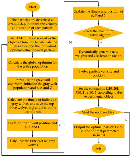
Figure 3.
GWOPSO algorithm flow chart.
3.2. Case Study of Benchmark Function
To fully validate the optimization performance of the project, this work selected eight classical benchmark object functions that have been widely used for optimization testing. Table 4 shows the benchmark functions and their characteristics. The eight benchmark functions are divided into two different types according to their function characteristics: unimodal functions and multimodal functions. Among them, f1–f4 are unimodal functions, which only contain one global optimum, so these functions can detect the development capacity of the method, while multimodal functions (f5–f8) contain multiple local optimums; although the global optimum is challenging to locate, it may be used to assess the algorithm’s capacity for global exploration [35]. Furthermore, the benchmark functions selected should have different features in terms of the scalability, separability, and dimensionality to be genuinely effective in objectively assessing new algorithms in an unbiased manner. The benchmark functions presented in Table 4 consist of separable and non-separable functions [36]. Since each variable in a separable function is independent of the others, they are relatively easy to solve, such as f1. Another problem that the algorithm may encounter is the scaling problem with many orders of magnitude differences, such as f4. Additionally, the complexity of the problem usually rises as its dimension increases. This dimensionality may be a significant obstacle for nearly all optimization algorithms for highly non-linear issues [37]. As a result, in this study, the functions of various dimensions are chosen for testing.

Table 4.
Benchmark functions.
The GWOPSO algorithm is used to optimize the eight benchmark functions and is contrasted with the conventional PSO algorithm, GWO algorithm, and GA algorithm. These algorithms have been shown to have a good optimization performance and have been implemented in a variety of sectors of study and engineering [38]. Therefore, comparing the GWOPSO algorithm proposed in this paper with it can verify whether the GWOPSO algorithm has superiority in optimizing the performance.
In order to ensure fairness and prevent errors caused by randomness, the basic parameters of the four algorithms selected for comparison are consistent: the initial population size is 50, and the total of the iterations is 100. Each test function is independently tested 30 times. The mean and standard deviation of the optimization findings are recorded and the empirical values are shown in Table 5, which is dimensionless. At the same time, to visually analyze the constriction of the algorithm, Figure 4 shows the convergence comparison of the four methods to the benchmark object functions.

Table 5.
Results of benchmark functions.
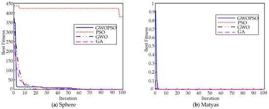
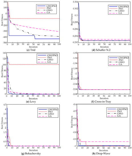
Figure 4.
Convergence curves.
The fitness mean and standard deviation in Table 5 reflect the convergence accuracy and stability of different algorithms under a given number of independent runs, respectively. The bold data in the table are the best test results. Figure 4 shows the optimal convergence curve of each algorithm on the benchmark function so that the constriction performance of the four methods may be compared intuitively. Through Table 5 and Figure 4, it is shown that on the unimodal function f1–f4, the GWOPSO algorithm maintains a high constriction rate from the beginning of the iteration and obtains the global optimum of the functions f3 and f4. For the functions f1 and f2, the optimization accuracy of the GWOPSO algorithm is second only to the GWO algorithm, but the GWOPSO algorithm has a faster convergence speed. At the same time, the standard PSO algorithm is trapped in the local optimum on these functions. The GWOPSO algorithm not only discovers the global optimum but also outperforms the other three algorithms in terms of the search accuracy, as indicated by the std and mean of the function f4 in Table 5. Moreover, Figure 4d illustrates the GWOPSO algorithm’s excellent convergence speed for the function f4. On the multimodal functions f5–f8, the average fitness of the GWOPSO algorithm is smaller than that of the standard PSO algorithm and has a better stability. The convergence accuracy of the functions f5 and f7 is greatly improved, which indicates that the introduction of the GWO algorithm into the PSO algorithm is effective in improving the optimization accuracy of the original algorithm. For the f6 function, the four algorithms have successfully obtained the theoretical optimal solution, but according to the convergence curve in Figure 4f, the GWOPSO algorithm has the fastest constriction rate.
In summary, it can be concluded that the GWOPSO algorithm is generally better than the standard PSO algorithm, the GWO algorithm, and the GA algorithm, and the comprehensive optimization performance is particularly outstanding, showing a higher search accuracy, faster convergence, and better stability.
4. GWOPSO-PID Controller for PMSS Speed Control
Conventional PID controllers are linear controllers that are widely used in process control to enhance the instantaneous state and steady state behavior of the scheme. The input of the PID controller is mainly the deviation e(t) between the input signal rin(t) and the output signal yout(t). The output u(t) of the controller is obtained by performing proportional, integral, and differential operations on the deviation e(t), thus controlling the controlled object [39]. The PID controller’s continuous form is defined as follows:
where Kp is the proportional parameter; Kd is the derivative parameter; and Ki is the integral parameter.
In the design process of the PID parameters, the three independent variables Kp, Ki, and Kd have a very important effect on the dynamic property of the PMSS, such as stability and timeliness. The research shows that the system can achieve a quick reaction time and excellent controllability by selecting the appropriate three parameters [40]. In this study, the GWOPSO algorithm is proposed to optimize the PID controller, select the appropriate objective function, and determine the three-parameter combinations of Kp, Ki, and Kd. The goal function’s value is used to gauge how quickly the control system responds. In this paper, the ITAE performance index is introduced into the performance evaluation of the PID scheme as the objective function of the GWOPSO algorithm [41]. The ITAE is the absolute error multiplied by time, which penalizes the error that exists after a long time and is considered to be an important indicator for measuring the system’s performance. The ITAE can be written as:
Finding the PID controller with the optimum performance may be done by solving the three parameters tuning issue as a sort of optimal search problem for the three independent variables. The ITAE is converted into an objective function and the three PID parameters are labelled as the coordinate locations of the particles in space. The three parameters of the PID controller are determined after the GWOPSO algorithm is performed and the ideal objective function’s ITAE is derived. The ITAE function’s minimum value in the algorithm design is used to determine the best PID parameters during the iterative update procedure. The best particle position is chosen as the final PID parameter if the PID controller’s controllability satisfies the criteria of the engineering application. Figure 5 depicts the GWOPSO optimized PID control’s basic operation. The error value e(t) between the real-time speed detected by the speed sensor and the target speed is input to the PID controller and the ITAE performance indicator. The GWOPSO algorithm finds the optimal PID parameters by seeking the performance indicator. The PID controller operates on the error with the optimal parameters to obtain the controller output u(t), which is the input to the PMSS, to realize the constant speed control of the PMSS.
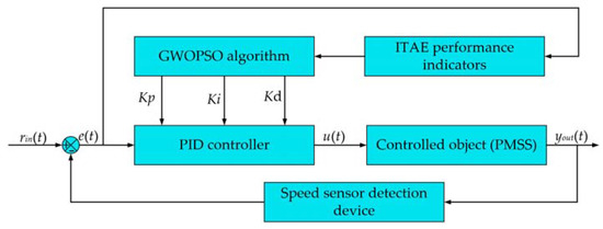
Figure 5.
GWO-PSOPID control schematic diagram.
5. Results and Discussion
Given the specification requirements of the experimental system, the controller should be designed to minimize the occurrence of a machine overload. In order to reduce cost losses, the GWOPSO algorithm operates under a non-linear constraint, thus determining the next sequence of the particle’s movements [42]. The PSO, GA, and GWO algorithms are also contrasted with the GWOPSO algorithm during the same period. To accomplish the concept of equity while comparing the four algorithms, the number of cycles, the scope of the parameter settings, and the optimal solution are adjusted to be under identical conditions. The following are three fundamental components that were used to evaluate the developed PID controller:
- (a)
- Temporal response characteristic.
- (b)
- Load disturbance response.
- (c)
- Robustness analysis.
Subject to a certain degree of measurement error, it was assumed in this study that the experimental results accurately represented the behavior of the hydraulic system under test. The simulation error is also constrained and falls within an established acceptable range [43]. As depicted in Figure 6, a simulation model was built with rotational speed serving as the system’s feedback. To validate the simulation model, a PMSS test bench was established, as shown in Figure 7. The hydraulic pump provided oil to the operational system, and the pilot pressure ranged from 0 to 35 bar. To measure the piston displacement, a pull-wire displacement sensor was installed externally on one side of the hydraulic cylinder. The motor swash plate’s initial position is locked during the experiment, and the speed sensor records the motor’s actual speed. The analogue signals from the displacement and speed sensors are converted into digital signals for the controller through a high-speed data acquisition module. The controller regulates the opening size of the solenoid valve according to the motor’s speed, which leads to a change in the extension length of the hydraulic cylinder piston rod and realizes the adjustment to the motor speed. Table 6 displays the technical specification of the aforementioned measuring equipment.
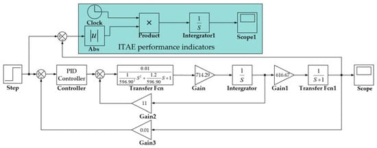
Figure 6.
Simulation model of PMSS.
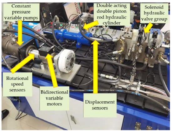
Figure 7.
Real photo of the PMSS test bench.

Table 6.
The technical specification of the main measuring equipment.
5.1. Temporal Response Characteristic
According to the actual working environment of the PMSS applied to large machinery, this paper reflects the tracking performance of the system through the response characteristics of the system under a no-load state. When the system is at no-load, the desired speed of the motor is set to 600 rpm [44]. By inputting a step signal to the PMSS, the dynamic response characteristics of the system under no-load conditions are analyzed. The step response curves under the no-load condition of the motor speed of the PMSS are shown in Figure 8.
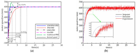
Figure 8.
Step response curves under no-load condition. (a) Simulation results; (b) experimental results.
As can be seen from Figure 8a, under conventional PID control, the motor speed reaches a steady-state regulation time of ts = 7.3 s with an overshoot of Mp = 13.6%, while under the GWOPSO-PID control, the system reaches a steady-state regulation time of only 2.4 s, a reduction of 67.1% compared to the conventional PID control, and no overshoot occurs. In addition, the GWOPSO-PID reduces the motor speed adjustment time by 64.7%, 78.6%, and 41.5% compared to the GWO-PID, PSO-PID, and GA-PID controls, respectively. To confirm the research observations, the aforementioned simulation results were validated using the PMSS actual architecture. The experimental system adopts the same GWOPSO-PID controller and the experimental results are shown in Figure 8b. The presence of equipment, manpower, and poor materials led to errors between the experimental system and the mathematical description. As a result, the experimental system responded slightly slower than in the simulation model and produced small oscillations in the step response tracking performance test at no load. Figure 9 displays the iteration curve for the ITAE. GWOPSO has the greatest exploring efficiency among the four methods, according to the ITAE iteration curve, demonstrating the best promotion capabilities.
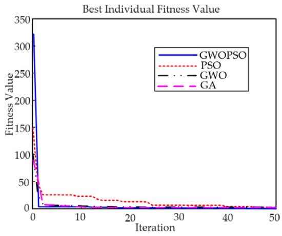
Figure 9.
The ITAE iteration curves under no-load condition.
5.2. Load Disturbance Response
In the actual working environment, the external load of construction machinery may increase or decrease slowly. During the simulation, the ramp signal in Simulink can be used to simulate this load condition. The part displays the PMSSs reduction potential using both the indicated controllers and several controllers that have undergone external disturbances testing. To emphasize the stability and accuracy of the proposed GWOPSO-PID controller for load disturbance in the PMSS, a ramp signal with a slope of −2 is created during the PMSS operation to simulate the system’s slowly changing load state. Figure 10 shows the dynamic response of the PMSS for a slow-varying load disturbance.
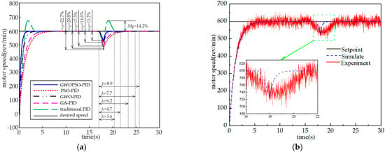
Figure 10.
Slow-varying load response of the PMSS. (a) Simulation results; (b) experimental results.
Combined with Figure 10 and Table 7, it can be seen that the GWOPSO-PID controller has a better control quality, with a lower overshoot and shorter regulation time to restore a rebalance when the external load state of the system changes slowly at 17 s compared to the conventional PID controller. The system speed loss ωp = 14.6% and the adjustment time ts = 3.02 s controlled by the GWOPSO-PID are much smaller than the other three control methods. As shown in the picture, when compared to existing controllers, the provided GWOPSO-PID controller has the best load torque reaction time in terms of the velocity degradation and rebalance regulation time. Figure 11 shows that the GWOPSO convergence curve swiftly increases in the initialization step and casually strolls the minimum ITAE during split rounds, thereby proving GWOPSOs excellent refining performance and ability to depart from the local optimal solutions. The load fluctuations are thus satisfactorily suppressed by the suggested regulator too.

Table 7.
PID parameters and dynamic response characteristic.
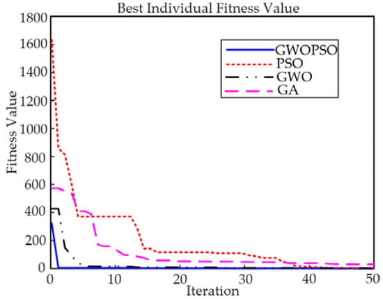
Figure 11.
The ITAE iteration curves under slow-varying load.
5.3. Robustness Analysis
In the actual working environment of construction machinery, the load on the motor shaft end may suddenly increase or decrease, and the load condition of the system at this time is a sudden-varying load. In the process of a simulation, the step signal in Simulink is usually used to replace this load condition. The behavior of the system is observed by the robustness analysis when subjected to the system uncertainties. A robust controller is very much required for a system for maintaining the system’s acceptable response in abnormal cases. In this paper, to demonstrate the robustness of the proposed method, a reverse step load torque is suddenly added to the PMSS at 15 s and the dynamic response characteristics of the system are analyzed.
It can be seen intuitively from Figure 12 that the actual speed of the motor is the same as the expected speed when the steady state is reached under the sudden-varying load state and the system loses speed at the moment of sudden-varying load loading. The conventional PID controlled PMSS has problems such as a large overshoot and long adjustment time. The GWOPSO-PID controller effectively improves the above situation. Additionally, compared to the GWO-PID control, PSO-PID control, and GA-PID control, GWOPSO-PID control reduces the amount of system speed loss ωp by 3.6%, 6.1%, and 2.5%, respectively, and the rebalancing regulation time ts by 35.5%, 44.3%, and 27.9%, respectively. The box plot displays the system stability by calculating the ITAE graphical dispersion. It can be seen from Figure 13 that the ITAE calculated by GWOPSO-PID has the smallest outlier and the lowest dispersion degree in all of the algorithms, which demonstrates that the GWOPSO-PID has an outstanding balance. The results further confirm the excellent robustness of the GWOPSO-PID controller. In addition, to further emphasize the stability of the GWOPSO-PID controlled PMSS, Figure 14 shows the Bode plot of the system. The Bode plot is closely linked to the time-domain response and visualizes the response characteristics of the input and output of the whole system. By adjusting the shape of the Bode plot, the design and verification of the controller can be realized. From Figure 14, we can visualize that the crossing frequency of the system is 28.2 rad/s, the phase margin is 86.1°, and the gain margin is 28.7 dB. When the open-loop logarithmic amplitude-frequency characteristic curve reaches the 0 dB line when its logarithmic phase-frequency characteristic curve is still above the −180° line, i.e., the phase is less than −180°, then the closed-loop system is stable.
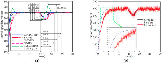
Figure 12.
Sudden-varying load response of the PMSS. (a) Simulation results; (b) experimental results.
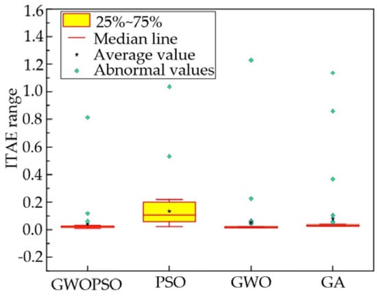
Figure 13.
The ITAE box plot.
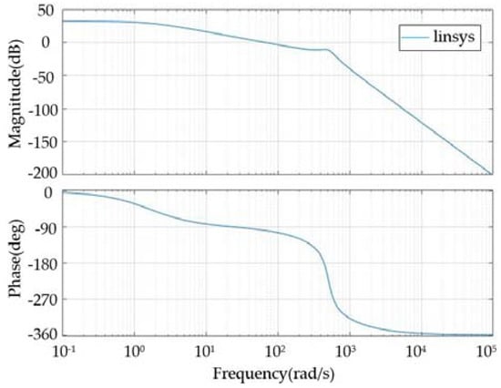
Figure 14.
The Bode diagram of the PMSS.
6. Conclusions
The PMSS is frequently implemented for the precise speed control of mechanical equipment and industrial processes. This research suggests a brand-new technique for the PMSSs speed control that applies a PID controller based on the GWOPSO algorithm to enhance the dynamic response characteristics and anti-interference capability of the system. The main conclusions can be summarized as follows:
- (1)
- We developed a novel hybrid optimization algorithm called GWOPSO. The GWOPSO-PID controller was designed for the PMSSs speed control. The PID controller optimized by GWOPSO has better parameters, so it presents higher control precision for the PMSS.
- (2)
- The GWOPSO-PID control PMSS simulation study and experimental verification. The system’s adjustment time to reach a steady state under no-load conditions is decreased by 78.6%, 64.7%, 67.1%, and 41.5%, respectively, compared to the conventional PID control, GWO-PID, PSO-PID, and GA-PID. The system responds more quickly.
- (3)
- We examined the system’s robustness and stability under various load scenarios. According to the results, under slow-varying load situations, the system’s speed loss is decreased by 9.5%, 1.4%, 7.6%, and 4.3%, and under sudden-varying load cases, the system’s rebalancing time is reduced by 48.9%, 35.5%, 44.3%, and 27.9%, respectively.
The control strategy created in this study is better able to suppress any potential system output variation brought on by load perturbations. In the future, to further actualize the autonomous control of higher-order non-linear systems, deep learning technology should be further coupled with this method.
Author Contributions
Conceptualization, H.W.; methodology, S.L.; writing—original draft preparation, S.L.; supervision, H.W; visualization, G.Z. (Guoqiang Zhou); funding acquisition, G.Z. (Guochao Zhao). All authors have read and agreed to the published version of the manuscript.
Funding
This research was funded by National Natural Science Foundation 52204169.
Data Availability Statement
Not applicable.
Conflicts of Interest
The authors declare no conflict of interest.
Nomenclature
| Abbreviations | |||
| PMSS | Pump–motor servo system | GA | Genetic algorithm |
| EHSS | Electro–hydraulic servo system | PID | Proportional–integral–derivative |
| GWO | Grey wolf optimization | ITAE | Integrated time and absolute error |
| PSO | Particle swarm optimization | ||
| Symbols | |||
| Qv | Output flow of the servo valve (m3/s) | Ap | Effective area of the hydraulic cylinder piston (m2) |
| Uv | Input voltage of the servo valve (V) | xp | Piston displacement (m) |
| ξv | Damping ratio of the servo valve (N/(m/s)) | βe | Equivalent bulk elastic modulus (Pa) |
| ωv | Natural frequency of the servo valve (Hz) | Vt | Total compression volume (m3) |
| UX | Output voltage of the displacement sensor (V) | Mt | Motor torque (N·m) |
| KL | Spring stiffness of the load (N/m) | PL | Load pressure of the hydraulic cylinder (N/m2) |
| Xp | Displacement of the hydraulic cylinder (m) | FL | Any external load force acting on the piston (N) |
| Ctp | Total leakage coefficient of the hydraulic cylinder (m3/(pa·s)) | ||
| mp | Total mass of the piston and the load converted to the piston (kg) | ||
| ΔP | Pressure difference between the inlet and outlet of the motor (Pa) | ||
| Jm | Equivalent moment of inertia converted from the motor and the load to the motor shaft (kg·m2) | ||
References
- Guo, Q.; Yu, T.; Jiang, D. Robust H∞ positional control of 2-DOF robotic arm driven by electro-hydraulic servo system. ISA Trans. 2015, 59, 55–64. [Google Scholar] [CrossRef]
- Shi, Y.; Li, S.; Wang, S.; Zhai, Y.; Tian, Y.; Yu, D.-L. Pitch angle control with fault diagnosis and tolerance for wind turbine generation systems. Proc. Inst. Mech. Eng. Part I J. Syst. Control Eng. 2021, 235, 1355–1366. [Google Scholar] [CrossRef]
- Meena, D.C.; Devanshu, A. Genetic algorithm tuned PID controller for process control. In Proceedings of the 2017 International Conference on Inventive Systems and Control (ICISC), Coimbatore, India, 19–20 January; pp. 1–6. [CrossRef]
- Zad, H.S.; Ulasyar, A.; Zohaib, A. Robust Model Predictive position Control of direct drive electro-hydraulic servo system. In Proceedings of the 2016 International Conference on Intelligent Systems Engineering (ICISE), Islamabad, Pakistan, 15–17 January 2016; pp. 100–104. [Google Scholar] [CrossRef]
- Shen, G.; Zhu, Z.; Zhao, J.; Zhu, W.; Tang, Y.; Li, X. Real-time tracking control of electro-hydraulic force servo systems using offline feedback control and adaptive control. ISA Trans. 2017, 67, 356–370. [Google Scholar] [CrossRef]
- Chen, X.; Li, D.; Yang, X.; Yu, Y. Identification recurrent type 2 fuzzy wavelet neural network and L2-gain adaptive variable sliding mode robust control of electro-hydraulic servo system (EHSS). Asian J. Control 2018, 20, 1480–1490. [Google Scholar] [CrossRef]
- Gao, B.; Shen, W.; Zhao, H.; Zhang, W.; Zheng, L. Reverse Nonlinear Sparrow Search Algorithm Based on the Penalty Mechanism for Multi-Parameter Identification Model Method of an Electro-Hydraulic Servo System. Machines 2022, 10, 561. [Google Scholar] [CrossRef]
- Samakwong, T.; Assawinchaichote, W. PID controller design for electro-hydraulic servo valve system with genetic algorithm. Procedia Comput. Sci. 2016, 86, 91–94. [Google Scholar] [CrossRef]
- Wu, X.; Zeng, F. Design of electro-hydraulic servo loading controlling system based on fuzzy intelligent water drop fusion algorithm. Comput. Electr. Eng. 2018, 71, 485–491. [Google Scholar] [CrossRef]
- Jia, L.; Zhao, X. An improved particle swarm optimization (PSO) optimized integral separation PID and its application on central position control system. IEEE Sens. J. 2019, 19, 7064–7071. [Google Scholar] [CrossRef]
- Fadel, M.Z.; Rabie, M.G.; Youssef, A.M. Optimization of Control Parameters Based on Genetic Algorithm Technique for Integrated Electrohydraulic Servo Actuator System. J. Mechatron. Autom 2019, 6, 24–37. [Google Scholar]
- Zheng, X.; Su, X. Sliding mode control of electro-hydraulic servo system based on optimization of quantum particle swarm algorithm. Machines 2021, 9, 283. [Google Scholar] [CrossRef]
- Wang, H.; Du, H.; Cui, Q.; Song, H. Artificial bee colony algorithm based PID controller for steel stripe deviation control system. Sci. Prog. 2022, 105, 00368504221075188. [Google Scholar] [CrossRef] [PubMed]
- Patel, R.; Kumar, V. Artificial neuro fuzzy logic PID controller based on BF-PSO algorithm. Procedia Comput. Sci. 2015, 54, 463–471. [Google Scholar] [CrossRef]
- Ye, Y.; Yin, C.-B.; Gong, Y.; Zhou, J.-J. Position control of nonlinear hydraulic system using an improved PSO based PID controller. Mech. Syst. Signal Process. 2017, 83, 241–259. [Google Scholar] [CrossRef]
- Le Dinh, H.; Temkin, I.O. Application of PSO and bacterial foraging optimization to speed control PMSM servo systems. In Proceedings of the 2018 IEEE Seventh International Conference on Communications and Electronics (ICCE), Hue City, Vietnam, 18–20 July 2018; pp. 1–6. [Google Scholar] [CrossRef]
- Fan, Y.; Shao, J.; Sun, G.; Shao, X. Proportional–integral–derivative controller design using an advanced lévy-flight salp swarm algorithm for hydraulic systems. Energies 2020, 13, 459. [Google Scholar] [CrossRef]
- Chen, P.; He, Z.; Chen, C.; Xu, J. Control strategy of speed servo systems based on deep reinforcement learning. Algorithms 2018, 11, 65. [Google Scholar] [CrossRef]
- Çelik, E.; Gör, H. Enhanced speed control of a DC servo system using PI + DF controller tuned by stochastic fractal search technique. J. Frankl. Inst. 2019, 356, 1333–1359. [Google Scholar] [CrossRef]
- Yu, B.; Zhu, Q.; Yao, J.; Zhang, J.-X.; Huang, Z.-P.; Jin, Z.; Wang, X. Design, mathematical modeling and force control for electro-hydraulic servo system with pump-valve compound drive. IEEE Access 2020, 8, 171988–172005. [Google Scholar] [CrossRef]
- Wang, X.; Feng, Y.; Sun, Y. Research on improved active disturbance rejection control of continuous rotary motor electro-hydraulic servo system. J. Cent. South Univ. 2020, 27, 3733–3743. [Google Scholar] [CrossRef]
- Ma, Y.; Gu, L.C.; Xu, Y.G.; Shi, L.C.; Wang, H.T. Research on control strategy of asymmetric electro-hydraulic servo system based on improved PSO algorithm. Adv. Mech. Eng. 2022, 14, 16878132221096226. [Google Scholar] [CrossRef]
- Yuan, H.B.; Na, H.C.; Kim, Y.B. System identification and robust position control for electro-hydraulic servo system using hybrid model predictive control. J. Vib. Control 2018, 24, 4145–4159. [Google Scholar] [CrossRef]
- Essa, M.E.S.M.; Aboelela, M.A.; Hassan, M.M.; Abdrabbo, S. Design of model predictive force control for hydraulic servo system based on cuckoo search and genetic algorithms. Proc. Inst. Mech. Eng. Part I J. Syst. Control. Eng. 2020, 234, 701–714. [Google Scholar] [CrossRef]
- Feng, H.; Ma, W.; Yin, C.; Cao, D. Trajectory control of electro-hydraulic position servo system using improved PSO-PID controller. Autom. Constr. 2021, 127, 103722. [Google Scholar] [CrossRef]
- Feng, H.; Song, Q.; Ma, S.; Ma, W.; Yin, C.; Cao, D.; Yu, H. A new adaptive sliding mode controller based on the RBF neural network for an electro-hydraulic servo system. ISA Trans. 2022, 129, 472–484. [Google Scholar] [CrossRef] [PubMed]
- He, Z.; Jiyun, Z.; Yunfei, W.; Zhonghai, Z.; Haigang, D.; Jiaxiang, M. Electro-hydraulic position servo system based on sliding mode active disturbance rejection compound control. Proc. Inst. Mech. Eng. Part C J. Mech. Eng. Sci. 2022, 236, 2089–2098. [Google Scholar] [CrossRef]
- Dhiman, G. SSC: A hybrid nature-inspired meta-heuristic optimization algorithm for engineering applications. Knowl.-Based Syst. 2021, 222, 106926. [Google Scholar] [CrossRef]
- Li, M.W.; Wang, Y.T.; Geng, J.; Hong, W.C. Chaos cloud quantum bat hybrid optimization algorithm. Nonlinear Dyn. 2021, 103, 1167–1193. [Google Scholar] [CrossRef]
- Yu, H.; Wang, H.; Li, N.; Zhao, G. Research on disturbance rejection control strategy of vehicle drive axle loading test bench. J. Theor. Appl. Mech. 2022, 60, 227–238. [Google Scholar] [CrossRef]
- Mirjalili, S.; Mirjalili, S.M.; Lewis, A. Grey wolf optimizer. Adv. Eng. Softw. 2014, 69, 46–61. [Google Scholar] [CrossRef]
- Shi, Y.; Eberhart, R. A modified particle swarm optimizer. In Proceedings of the 1998 IEEE International Conference on Evolutionary Computation Proceedings. IEEE World Congress on Computational Intelligence (Cat. No. 98TH8360), Anchorage, AK, USA, 4–9 May 1998; pp. 69–73. [Google Scholar]
- Wang, D.; Tan, D.; Liu, L. Particle swarm optimization algorithm: An overview. Soft Comput. 2018, 22, 387–408. [Google Scholar] [CrossRef]
- El-Kenawy, E.S.; Eid, M. Hybrid gray wolf and particle swarm optimization for feature selection. Int. J. Innov. Comput. Inf. Control 2020, 16, 831–844. [Google Scholar]
- Ahmadieh Khanesar, M.; Bansal, R.; Martínez-Arellano, G.; Branson, D.T. XOR Binary Gravitational Search Algorithm with Repository: Industry 4.0 Applications. Appl. Sci. 2020, 10, 6451. [Google Scholar] [CrossRef]
- Jamil, M.; Yang, X.S. A literature survey of benchmark functions for global optimization problems. arXiv 2013, arXiv:1308.4008. [Google Scholar] [CrossRef]
- Sharafi, Y.; Khanesar, M.A.; Teshnehlab, M. Discrete binary cat swarm optimization algorithm. In Proceedings of the 2013 3rd IEEE International Conference on Computer, Control and Communication (IC4), Karachi, Pakistan, 25–26 September 2013; pp. 1–6. [Google Scholar] [CrossRef]
- Zhang, X.; Lin, Q.; Mao, W.; Liu, S.; Dou, Z.; Liu, G. Hybrid Particle Swarm and Grey Wolf Optimizer and its application to clustering optimization. Appl. Soft Comput. 2021, 101, 107061. [Google Scholar] [CrossRef]
- Ren, H.P.; Gong, P.F. Adaptive control of hydraulic position servo system using output feedback. Proc. Inst. Mech. Eng. Part I J. Syst. Control. Eng. 2017, 231, 527–540. [Google Scholar] [CrossRef]
- Wrat, G.; Ranjan, P.; Bhola, M.; Mishra, S.K.; Das, J. Position control and performance analysis of hydraulic system using two pump-controlling strategies. Proc. Inst. Mech. Eng. Part I J. Syst. Control. Eng. 2019, 233, 1093–1105. [Google Scholar] [CrossRef]
- Nie, Y.; Zhang, Y.; Zhao, Y.; Fang, B.; Zhang, L. Wide-area optimal damping control for power systems based on the ITAE criterion. Int. J. Electr. Power Energy Syst. 2019, 106, 192–200. [Google Scholar] [CrossRef]
- Sánchez-López, C.; Carbajal-Gómez, V.; Carrasco-Aguilar, M.; Morales-López, F. PID controller design based on memductor. AEU-Int. J. Electron. Commun. 2019, 101, 9–14. [Google Scholar] [CrossRef]
- Wang, S.; Xu, Q.; Lin, R.; Yang, M.; Zheng, W.; Wang, Z. Feedback linearization control for electro-hydraulic servo system based on nonlinear disturbance observer. In Proceedings of the 2017 36th Chinese Control Conference (CCC), Dalian, China, 26–28 July 2017; pp. 4940–4945. [Google Scholar] [CrossRef]
- Tran, N.H.; Le, C.; Ngo, A.D. An investigation on speed control of a spindle cluster driven by hydraulic motor: Application to metal cutting machines. Int. J. Rotating Mach. 2019, 2019, 4359524. [Google Scholar] [CrossRef]
Disclaimer/Publisher’s Note: The statements, opinions and data contained in all publications are solely those of the individual author(s) and contributor(s) and not of MDPI and/or the editor(s). MDPI and/or the editor(s) disclaim responsibility for any injury to people or property resulting from any ideas, methods, instructions or products referred to in the content. |
© 2023 by the authors. Licensee MDPI, Basel, Switzerland. This article is an open access article distributed under the terms and conditions of the Creative Commons Attribution (CC BY) license (https://creativecommons.org/licenses/by/4.0/).