Abstract
Measurement technology based on machine vision has been widely used in various industries. The development of vision measurement technology mainly depends on the process of photosensitive components and the algorithm of processing a target image. In the high-precision dimension measurement of machined metal parts, the high-resolution imaging device usually exposes the cutting texture of the metal surface and affects the accuracy of measurement algorithm. At the same time, the edges of machined metal parts are often chamfered, which makes the edges of objects in the picture overexposed in the lighting measurement environment. These factors reduce the accuracy of dimensioning metal parts using visual measurements. The traditional vision measurement method based on color/gray image makes it difficult to analyze the physical quantities in the light field except for the light intensity, which limits the measurement accuracy. Polarization information can more carefully depict the edge contour edge information in the scene and increase the contrast between the foreground and the background. This paper presents a method to improve the measurement accuracy of machined metal parts by using polarization vision. The incident angle of the light source is optimized according to the complex refractive index of the metal material, and the degree of polarization image with enhanced edge contour features of the ROI (region of interest) is obtained. The high-precision measurement of cylindrical brass motor components is realized by using the method of reprojection transformation correction and maximum correlation template matching (NCC) for rough positioning, as well as the method of edge extraction and optimal fitting. The experimental results show that for copper parts with a tolerance range of mm, the average measurement error and maximum measurement error are within mm, which are higher than the existing color/gray image measurement methods.
1. Introduction
Various measurement methods are proposed to meet the increasing requirements of manufacturing accuracy. Measurement technology can be divided into contact measurement and non-contact measurement. Contact measuring instruments include micrometer, CMM, comparator, etc. Non-contact measurement methods include laser measurement, ultrasonic measurement, visual measurement, etc. Contact measurement often relies on high-precision mechanical equipment, but it will lead to inevitable misreading and mis-operation, which will reduce accuracy. Although CMM has high accuracy, with the wear of mechanical components, errors will occur in use and detection [1]. Laser scanning measurement has high requirements for the geometry of the measured object. It is greatly affected by the environment, and the accuracy is low when the amount of scanning data is large [2]. The fringe interferometry method can obtain high measurement accuracy, but its measurement optical path interference structure is relatively complex, and the construction and debugging of the hardware and software platform are cumbersome [3]. The accuracy of ultrasonic measurement is lower than that of other measurement methods. Visual measurement technology is widely used in industrial production because of its non-contact, high precision and high stability. The visual measurement system is composed of hardware and software. The hardware system mainly includes a light source, image sensor, optical lens, industrial computer and other related hardware equipment. An image processing algorithm and other technical requirements compose the software part [4].
The vision measurement method was first proposed by Pentland (1987), and its basic principle is to calculate the actual size through the pixel size obtained by the calibration object. The visual measurement method is widely used in dimension measurement of machined metal parts. Hueckel M.F (1975) [5] proposed a sub-pixel edge detection method based on curve fitting to further improve the measurement accuracy. Takesa K [6] completed the measurement of cylindrical machined parts with a single camera, and the relative error is within 0.05%. With the improvement of manufacturing level, the integration of optical sensors has reached tens of millions of pixel resolution. Therefore, the measurement accuracy of small and medium-sized machined parts is required to be higher and higher. Due to the inability to effectively eliminate the texture of the metal surface, Ping Chen [7] made a binary image segmentation of the object and background in the measurement algorithm. The quality of image segmentation directly affects the measurement accuracy. Therefore, it is necessary to correct the rotation projection of the segmented object and compensate the extracted edge pixels of the object, so as to improve the stability of the measurement results. Deep learning is widely used in the field of image segmentation, especially in the segmentation of medical images. However, segmentation in changing scenes is still a challenge, and the robustness of distinguishing false edges needs to be improved [8,9,10,11,12]. A more common way to improve measurement accuracy is to design more reliable sub-pixel edge extraction operators [13,14,15,16]. The premise for this method to achieve good results is that the image has sharp edges.
At present, most vision measurement algorithms deal with images based on illumination intensity. Other physical quantities in the light field are difficult to be used in ordinary color/gray-scale images. In polarized visual imaging, the light reflected by the measured object enters the optical sensor through polarizers with different polarization angles. The sensor can capture multiple groups of linearly polarized light images, so as to obtain optical physical quantities such as degree of polarization, polarization angle, intensity of polarized light and so on. The degree of polarization of the object in the image is affected by the incident angle and the complex refractive index of the object material. The foreground and background in the image can be well segmented by using the degree of polarization. The objects in the polarization image have sharper and separable edges and less optical noise. In this paper, a measurement scheme of machined parts based on polarization vision is designed, which can improve the measurement accuracy and has good robustness to the environment. Through the polarization sensor, the light intensity images with multiple polarization angles can be collected, and the polarization images with different angles can be calculated by Stokes formula. The actual size of the object can be calculated by image processing of the acquired polarization image.
2. Hardware Platform Design
2.1. Hardware Device Selection
Figure 1a is the processing drawing of the machined copper motor parts to be measured, and its photo is on the upper right corner. What needs to be measured is the length of the part, nominal dimension of which is mm and the tolerance is mm. The images obtained by bright field illumination, dark field illumination and the polarization system are shown in Figure 1. The image (Figure 1b) collected by monochrome industrial camera for bright field illumination has many cutting textures. The spiral texture produced by the high-speed rotation of the material and cutting by the cutter during the production is exposed in the high-resolution picture. The edge and background are difficult to distinguish, so it is hard to achieve accurate foreground segmentation. The image collected by monochrome industrial camera for dark field illumination (Figure 1c) has high-quality edge contrast and less noise. Due to the chamfer on the edge of the part, the overexposure of the edge of the object in the image makes it difficult to distinguish the specific position of the edge. This situation is common in the measurement of machined parts, so it is difficult to improve the measurement accuracy. The polarization image (Figure 1d) has obvious foreground and background differentiation, and the edge of the object is clear and sharp, which is convenient for image processing to calculate the size of the motor component. It can be seen from Figure 1e,f that the polarization degree images of objects with different materials including wood, copper, aluminum and iron can show sharp edges. In the same environment, the edge contrast of different objects in the polarization degree image is different. The gray value of polarization degree image is related to the complex refractive index of the object material and the incident angle of the light source. When the material of measured object is determined, a better image can be obtained by adjusting the lighting angle.
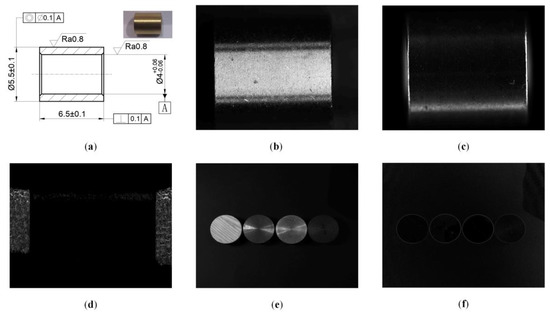
Figure 1.
Results of different lighting schemes. (a) CAD drawing and photo of objects. (b) Bright field illumination grayscale image. (c) Gray image of dark field illumination. (d) Polarization degree image. (e) Gray scale images of objects of wood, copper, aluminum and iron from left to right. (f) Polarization degree images of objects.
The polarization vision measurement platform adopts a Daheng mercury monochrome array polarization camera with model MER-502-79U3M-L POL to collect polarization images of motor components. The object telecentric lens with optical magnification of 1, focal length of 7 mm and working distance of 110 mm is used to obtain the field of view matching with the motor assembly, which can also eliminate the influence of image radial distortion on the measurement accuracy. A non-polarized LED strip light source is used for bright field illumination, as shown in Figure 2. The relevant color temperature of the light source is 1127 K, the main wavelength is 602.5 nm, the peak wavelength is 608.7 nm, and the full width at half maxima is 15.9 nm.
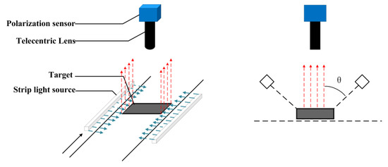
Figure 2.
Schematic diagram of hardware platform.
2.2. Polarization Degree Image Acquisition
The polarization degree image refers to an image in which the polarization degree is represented by the gray value of the pixel unit. In visual measurement, the polarization image enhances the contrast between the foreground and the background, resulting in a clear and sharp outline of the object to be measured [17]. After the electromagnetic wave is reflected and radiated by the surface of the object, the polarization state will change due to the influence of its surface material, texture, and incident angle. The degree of polarization is the ratio of the light intensity of the polarized portion of the beam to the overall light intensity. For polarizers, the degree of polarization is the ratio of the difference between the transmitted light intensities of the two optical axes to the sum of the transmitted light intensities, as shown in Formula (1):
where is the degree of polarization, and are the light intensities of the two optical axes parallel and perpendicular to the light propagation direction, respectively. Formula (1) can be calculated by the parameters in the Stokes vector :
where and represent the amplitudes of the light wave components along the propagation direction and perpendicular to the propagation direction, respectively, and represent the phase difference between the two components.
in the Stokes parameter are usually expressed as . represents the total intensity of the light wave, represents the intensity difference between the linearly polarized light in the x-direction and the y-direction, and represents the intensity difference between the linearly polarized light in the π/4 direction and the −π/4 direction. indicates whether the right-handed or left-handed circularly polarized component is dominant, which is assumed as 0 in this paper. Daheng mercury monochrome array polarization camera adopts Sony IMX250MZR CMOS polarization sensor chip with global exposure, which can simultaneously collect images of four different light directions of 0°, 45°, 90°, and 135° (Figure 3a). In the polarized light-sensing chip, four adjacent pixels with light intensities are an imaging unit. Among them, represents the polarized light intensities in four different directions of 0°, 45°, 90°, and 135°. According to the definition of the degree of polarization, the Stokes vector can be rewritten as:
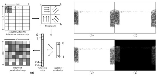
Figure 3.
(a) Schematic diagram of polarization imaging. (b) Zero-degree polarized image. (c) Forty-five-degree polarized image. (d) Ninety-degree polarized image. (e) Polarization image.
By substituting Formula (8) into Formula (3), the polarization degree value P of a single imaging unit can be obtained. By linearly mapping the polarization degree P with the interval range [0, 1] to the grayscale interval with the interval range [0, 255], the polarization degree image composed of the polarization degree information can be obtained (Figure 3a). The size of the gray value linearly reflects the degree of polarization of the pixel. The polarization images of the copper motor components with polarization angle of 0° (Figure 3b), 45° (Figure 3c), and 90° (Figure 3d) are calculated by the Stokes vector to obtain the corresponding polarization images (Figure 3e).
2.3. Selection of Lighting Angle
Light having the same amplitude in any direction is called non-polarized light. According to the Fresnel formula, when light passes through the boundary of different media, it is partially reflected and partially refracted. The different refractive index and reflectivity of the components parallel to and perpendicular to the light wave cause the non-polarized light to be reflected by the object surface to form partially polarized light. When the incident angle is equal to the Brewster angle, the reflected light is linearly polarized light. Partially polarized light is mixed with polarized light and non-polarized light. A polarization image with a specific polarization angle can be captured by a polarization camera (optical sensor + linear polarizer). The degree of polarization of light reflected by an object depends on the angle of incidence of the light and the material properties of the object [18]. Choosing the optimal lighting angle can improve the polarization degree of the motor assembly in the image, thereby improving the accuracy of visual measurement [19]. In order to calculate the optimal lighting angle, the definition in Formula (1) of the degree of polarization is rewritten as an expression about the reflectivity R and the emissivity [20]. Specular reflection, diffuse reflection and diffraction all affect the polarization of light. Since the roughness of the tested sample is required to be Ra 0.8 and the texture period of the cutting process is much greater than the wavelength of the light, both diffraction and diffusion are ignored in the analysis. Fresnel’s reflection law is used to resume the degree of polarization model. The Formula (9) is obtained as follows:
where and are the reflectances of the vibration components in the parallel and vertical directions of the light vector on the surface of the medium, respectively. represents the angle of incidence and reflection of the reflected radiation. The incident angle and the reflection angle of the reflected radiation are numerically the same as the incident angle of the object irradiated by the light source. The value of and can be obtained by the Fresnel formula:
where is the refractive index of the smooth medium surface. The Fresnel formula is generally used to reflect the energy relationship of radiation reflected by non-absorbing media. Referring to the improved method proposed by JW Paker [21], the Fresnel formula is rewritten with the refractive index in complex form. The refractive index in the formula should be replaced by a complex refractive index formula that reflects energy dissipation:
where is the refractive index of the material and k is the extinction coefficient of the material. The complex refractive index is also related to the material properties of the object and the wavelength of the radiated light. The complex refractive index of common materials at different radiation wavelengths can be obtained by consulting the technical manual. When the complex refractive index of the material is determined, the Formulas (9)–(12) are combined to establish the mapping relationship between the polarization degree and the incidence angle [22]. represents the zenith angle, and its physical meaning is the angle between the incident light, the reflected light and the surface normal. The zenith angle is numerically the same as the incident angle.
Under the visible light radiation with a wavelength of 600 nm, the complex refractive index of the surface of the copper motor component is checked as follows:
According to Formula (13), combined with the complex refractive index of the motor assembly, the relationship between the degree of polarization and the observation angle is obtained (Figure 4a). In the incident angle degree of polarization model, the object surface is assumed to be approximately planar. The angles of incidence are considered to be the same everywhere on the surface of the object. When the observation angle is 61.7°, the polarization degree of each pixel in the image is the largest and the middle part of the polarization image provides sharper object edge information. in Figure 2 and in Formula 13 represent the angle between the incident light and the surface normal. Since the surface of the object to be measured is a curved surface rather than a plane, the surface normal is not parallel to the light path reflected to the optical lens. Therefore, the zenith angle of all points on the object surface is not equal to the illumination angle (the angle between the lighting direction and the lens). The theta of the area closer to the horizontal plane is closer to the lighting angle, which is the reason why the middle part of the object has a good imaging effect, while the top and bottom are weakened, as is shown in Figure 4b—60°.
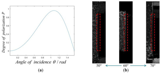
Figure 4.
Adjustment scheme of lighting angle. (a) Degree of polarization observation angle function. (b) Image with different degrees of polarization at incident angles.
3. Algorithm Design
The schematic flow chart of the algorithm designed in this paper (Figure 5) is divided into a coordinate system conversion module, a dimension measurement module and a judgment module. The essence of the length measurement algorithm is to calculate the actual size (pixel accuracy) of a single pixel and calculate the actual length of the object according to the number of pixels occupied by the object in the measurement direction. In the process of designing the algorithm, the working conditions of the collected images are considered, and the world coordinate system is reprojected to eliminate the measurement errors caused by the different poses of the measured objects; Gaussian filtering, NCC template matching coarse positioning, morphological operation ROI extraction, Canny operator edge extraction, and least squares line fitting are performed on the image to find the effective edge of the object to be measured. Finally, its length is calculated to judge whether it meets the tolerance requirements.
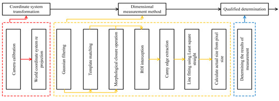
Figure 5.
Diagram of algorithm design.
3.1. Coordinate System Conversion Module
In 2D vision measurement, because the plane of the object to be measured is not perpendicular to the camera lens, there is a certain transformation relationship between the collected image and the object itself. Such a transformation relationship causes the object to be measured to be stretched, compressed or slanted in the image, which affects the accuracy of visual measurement. Therefore, it is very necessary to vertically project the world coordinate system along the Z-axis (optical path) direction into the camera coordinate system in the visual measurement, and then transform the camera coordinate system into the image coordinate system.
The optical principle of polarization imaging is the same as that of traditional visual imaging. Therefore, the calibration method of the traditional camera is also applicable to the polarization camera. According to Zhang’s calibration method [23], the camera is calibrated with a checkerboard calibration board, and the internal parameter matrix and the external parameter matrix are obtained .
The mapping relationship between the point on the calibration board in the world coordinate system and the corresponding point in the image coordinate system is as follows:
The mapping relationship between the point on the calibration board in the world coordinate system after vertical projection transformation and the corresponding point in the image coordinate system is as follows:
According to Formula (17) and Formula (18), the mapping relationship between the point on the original image calibration board and the point on the corrected image calibration board can be obtained:
In the above formula:
According to the rigid transformation matrix , the original image can be corrected, so that the surface of the part to be measured is perpendicular to the camera coordinate system (Figure 6), so as to avoid the influence of the position of the object on the accuracy of visual measurement.
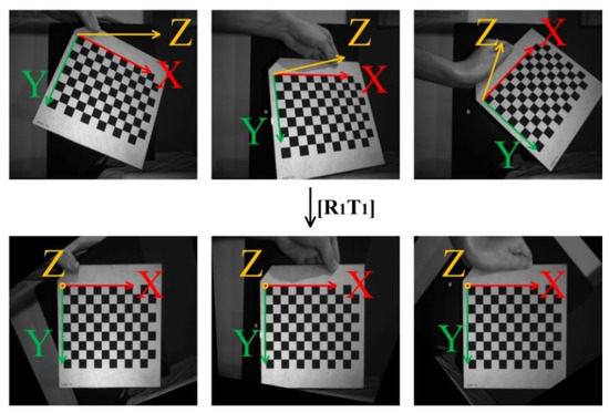
Figure 6.
World coordinate projection renderings.
3.2. Dimensional Measurement Module
Gaussian filtering is performed on the image to remove system noise. The template matching method is used for rough positioning and ROI interception of the part to be tested in the image. Since the object targeted by the image algorithm is only the part of the field of view that contains the workpiece to be measured, the template is established. Place the template T in the search graph for traversal. The area covered by the template in the search graph is denoted as a subgraph , where and are the coordinates of the upper left corner of the subgraph, and the search range is: , . Using the correlation method to calculate the correlation between template T and subgraph :
Normalize it to mean:
The maximum value of R in the process of traversing the search graph of the template is selected as the best matching result (Figure 7). The coordinates of the sub-image are the coarsely positioned image coordinates.
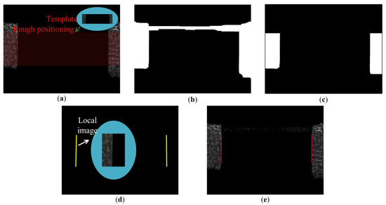
Figure 7.
Image processing flow. (a) Template matching. (b) Morphological processing. (c) ROI interception. (d) Canny operator edge extraction. (e) Least square linear fitting.
A morphological closing operation was performed on the original image to sharpen the contours (Figure 8). The morphological closing operation is to dilate and then erode the image, that is, to perform Minkowski addition and Minkowski subtraction operations.
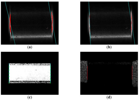
Figure 8.
Comparison results of different measurement methods (a) Method 1; (b) Method 2; (c) Method 3; (d) Method 4.
Boolean AND operation is performed on the template matching region and the morphological closed operation image to obtain the region that needs further processing (Figure 7b).
Use the Canny operator to extract the edge of the object to be measured. The convolution template of the Canny operator in the direction and the convolution template of the Canny operator in the direction are:
The mathematical expressions of the partial derivative in the X direction, the partial derivative in the Y direction, the gradient magnitude and the gradient direction of the pixel point of the coordinate are:
Then, non-maximum suppression is performed on the gradient amplitude of each pixel point. If the gradient magnitude of a pixel is larger than the gradient magnitude of any pixel in its neighborhood, the gray value of the pixel is retained, and if the gradient magnitude of the pixel is not the maximum value in its neighborhood, the gray value of the pixel is set to 0. The gray value N of the pixel with coordinates after non-maximum suppression is:
Edge straight lines were fitted using the least squares method (Figure 7d). Represent a straight line in Hesse normal form:
This is an over-parameterized representation, in which , the distance of the point to the line can be obtained directly from . Fitting is performed by the least squares method, that is, the sum of the squares of the distances from the points on the contour of the image to the line is the smallest:
In order to avoid , the zero-error solution, the Lagrange multiplier is introduced as a constraint condition for straight line fitting.
Finally, the actual size is calculated according to the pixel accuracy, as shown in Figure 7d.
3.3. Judgment Module
The measured length of machined copper motor parts is mm and the allowable error range is mm. If the measured size meets the tolerance requirements of the part, it will be judged as qualified, otherwise, it will be judged as unqualified.
4. Experimental Analysis
The measurement method of polarization vision is compared with the current Method 1 (Fang, 2020 [15]), Method 2 (Jia, 2021 [16]), and Method 3 (Ping Chen, 2014 [7]) with high accuracy (Figure 9). The three methods have their own characteristics. Fang extracted the sub-pixel level edge through cubic interpolation in the size measurement algorithm to measure the size. Jia improved the Canny operator to make the extracted edge more fit the machined part. Chen performed image clustering to segment the measured part before lifting the weight edge. A polarization camera and an ordinary black and white industrial camera were used to collect the polarization degree image of the motor assembly with a resolution of 2048 × 2448 and the grayscale image of the motor assembly bright field illumination and dark field illumination with a resolution of 5472 × 3648 for visual measurement experiments (Figure 8). In the experiment, a total of 100 groups of motor components were measured for size, and each part was measured 10 times by manual random feeding, and a total of 1000 measurement experiments were carried out. The measurement results are compared with those obtained with an electronic micrometer. Some assumptions about the experimental process are as follows:
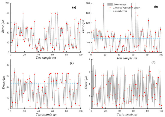
Figure 9.
Error diagram of different methods. (a) Method 1. (b) Method 2. (c) Method 3. (d) Method 4.
- (1)
- The result obtained by the electronic micrometer is considered to be the true length of the object. The accuracy of the micrometer is 0.01 mm, and the reading of the micrometer can be estimated to be 0.001 mm, so the error of 0.001 mm level is inaccurate.
- (2)
- The error less than 0.01 mm in each visual measurement error obtained from the measurement standard of electronic micrometer is inaccurate, which only represents that the measurement accuracy of this method has reached the level of 0.01 mm.
Method 1 (Figure 8a) and Method 2 (Figure 8b) are not effective in extracting object edge contours and cannot discriminate false edges. Method 3 (Figure 8c) and the method proposed (Figure 8d) can effectively extract the edge contour of the object. Linear regression analysis was performed on the measurement data of methods 1–4 and the real data (Figure 9). The stability of the method proposed in this paper is better and the measurement error is smaller. Table 1 is obtained by quantitative analysis of the above experimental data.

Table 1.
Experimental results of visual measurement comparison.
The part of the data within 0.01 mm by micrometer is estimated, so the experimental data in Table 1 cannot show the true accuracy of the method proposed in this paper, but only gives a lower limit. It can be seen that the pixel resolution of the polarization image adopted by the method proposed is low, the average measurement error is 3.53 μm, the maximum repeated measurement error is 6.86 μm, and the maximum measurement error is 7.06 μm, which are lower than ordinary grayscale image measurement method. Although the error part within 0.01 mm is inaccurate, the measurement error in Table 1 proves that the measurement accuracy of the method proposed reaches 10 μm, which is not achieved by other ordinary grayscale image measurement methods.
In the methods of traditional vision measurement, the average error of the measurement obtained by the dark field illumination scheme exceeds 50 μm, and the average error obtained by the bright field illumination scheme exceeds 20 μm. It can be seen from Figure 1 that an object with a length of 6500 μm occupies most of the space in the image. Analyzing the pixel equivalent in the direction of width through the resolution of the optical sensor, the actual size of a single pixel in the traditional vision measurement scheme is about 2 μm, and the actual size of a single pixel in polarization vision is about 3 μm. It can be seen from Table 1 that the method proposed achieves the accuracy of pixel level. However, the method of traditional vision measurement errors of tens of pixels. The processing texture in the bright field lighting scheme shown in Figure 1b results in that the boundary part on the right side of the object is not illuminated by the light source. This situation leads to tens of pixel deviations in the edge extraction process. In the dark field lighting scheme shown in Figure 1c, the edge overexposure area occupies tens of pixels in the width direction of the image. The edge of object cannot be accurately extracted in the over-exposure area. Because the over-exposure area occupies too many pixels in the image width direction, the measurement error is larger than that of the open-field lighting scheme. The method of polarization measurement proposed can image the object edge with high quality after optimizing the light angle, so the error caused in the edge extraction is smaller. The maximum measurement error of the method proposed in this paper is within 10 μm and is smaller than that of traditional visual measurements, because degree of polarization image is less affected by light. Hence, the measurement system proposed is relatively stable.
Figure 9 further shows the accuracy and stability of the method proposed and the traditional visual measurement method. The rectangular red points in the figure represent the average error of ten repeated measurements of a single sample. The part surrounded by the maximum and minimum values in the repeated measurement results of each sample is filled with gray. The blue dotted line represents the average error of 1000 measurements of 100 samples. The global error and repeated error of the measurement method proposed are smaller than those of traditional visual measurement methods, which verifies the superiority of the method using polarization model for visual measurement.
5. Conclusions
In this paper, a high-precision length measurement method based on polarization vision for cylindrical machined parts is proposed. The angle of illumination is designed according to the complex refractive index and polarization imaging model, which provides an important basis for obtaining high-quality polarization images. Compared with traditional visual measurement, the object edge image obtained by the method is sharper and less affected by ambient light, which provides support for improving the length measurement accuracy of cylindrical machined parts. The experimental results show that the measurement accuracy reaches at least 0.01 mm, which is higher than other visual measurement methods.
However, the method only considers the 2D measurement field in the process of optimizing the illumination angle for polarization image. When the measurement requirement extends to 3D measurement, especially when the depth of the object edge fluctuates greatly, the optimization of the illumination angle needs to be further studied. The strong anti-interference of the polarization degree image and the characteristics of weakening the internal edge of the object can be studied under more working conditions, such as visual measurement underwater and visual measurement in the environment of smoke, which is also a direction worthy of study in the future.
Author Contributions
Conceptualization, Z.T. and Y.J.; methodology, Z.T. and Y.J.; software, Y.J. and W.F.; validation, Z.T., Y.J. and W.F.; formal analysis, Z.T., Y.J. and W.K.; investigation, W.F., W.K. and X.T.; resources, Z.T.; data curation, Z.T., Y.J. and W.K.; writing—original draft preparation, Z.T. and Y.J.; writing—review and editing, Z.T., Y.J. and W.F.; visualization, Z.T.; supervision, X.X. and M.L.; project administration, Z.T.; funding acquisition, Z.T. All authors have read and agreed to the published version of the manuscript.
Funding
This research was supported by the Key R&D plan of Jiangsu Province (Grant No. BE2020082-1).
Institutional Review Board Statement
Not applicable.
Informed Consent Statement
Not applicable.
Data Availability Statement
Not applicable.
Conflicts of Interest
The authors declare no conflict of interest.
References
- Qiangxian, H.; Hujuan, Y.; Jianzhao, Q. Advances in Probes of Micro-Nano Coordinating Measuring Machine. China Mech. Eng. 2013, 24, 1264–1272. [Google Scholar]
- Yang, H.; Xu, X. Intelligent Crack Extraction Based on Terrestrial Laser Scanning Measurement. Meas. Control 2020, 53, 416–426. [Google Scholar] [CrossRef]
- Xu, X.; Zhang, L.; Yang, J.; Cao, C.; Wang, W.; Ran, Y.; Tan, Z.; Luo, M. A Review of Multi-Sensor Fusion SLAM Systems Based on 3D LIDAR. Remote Sens. 2022, 14, 2835. [Google Scholar] [CrossRef]
- Yu, J.; Cheng, X.; Lu, L.; Wu, B. A Machine Vision Method for Measurement of Machining Tool Wear. Meas. J. Int. Meas. Confed. 2021, 182, 109683. [Google Scholar] [CrossRef]
- Hueckel, M.H. An Operator Which Locates Edges in Digitized Pictures. J. ACM 1971, 18, 113–125. [Google Scholar] [CrossRef]
- Takesa, K.; Sato, H. Measurement of Diameter Using Charge Coupled Device. Trans. Jpn. Soc. Mech. Eng. Ser. C 1985, 51, 969–978. [Google Scholar] [CrossRef]
- Chen, P.; Chen, F.; Han, Y.; Zhang, Z. Sub-Pixel Dimensional Measurement with Logistic Edge Model. Optik 2014, 125, 2076–2080. [Google Scholar] [CrossRef]
- Carreras, I.A.; Turaga, S.C.; Berger, D.R.; San, D.C.; Giusti, A.; Gambardella, L.M.; Schmidhuber, J.; Laptev, D.; Dwivedi, S.; Buhmann, J.M.; et al. Crowdsourcing the Creation of Image Segmentation Algorithms for Connectomics. Front. Neuroanat. 2015, 9, 142. [Google Scholar] [CrossRef]
- Schoneberg, J.; Raghupathi, G.; Betzig, E.; Drubin, D. 3D Deep Convolutional Neural Networks in Lattice Light-Sheet Data Puncta Segmentation. In Proceedings of the 2019 IEEE International Conference on Bioinformatics and Biomedicine—BIBM, San Diego, CA, USA, 18–21 November 2019. [Google Scholar]
- Pan, Z.; Xu, J.; Guo, Y.; Hu, Y.; Wang, G. Deep Learning Segmentation and Classification for Urban Village Using a Worldview Satellite Image Based on U-Net. Remote Sens. 2020, 12, 1574. [Google Scholar] [CrossRef]
- Ghosh, S.; Das, N.; Das, I.; Maulik, U. Understanding Deep Learning Techniques for Image Segmentation. ACM Comput. Surv. 2019, 52, 73. [Google Scholar] [CrossRef]
- Gite, S.; Mishra, A.; Kotecha, K. Enhanced Lung Image Segmentation Using Deep Learning. Neural Comput. Appl. 2022. [Google Scholar] [CrossRef] [PubMed]
- Li, B. Research on Geometric Dimension Measurement System of Shaft Parts Based on Machine Vision. EURASIP J. Image Video Process. 2018, 2018, 101. [Google Scholar] [CrossRef]
- Liu, Z.D.; Liao, Q. Automatic Measurement of Oil Volume in Checkout of Oil Pumps Based on Machine Vision. J. Adv. Manuf. Syst. 2008, 7, 85–89. [Google Scholar] [CrossRef]
- Fang, Z.; Xiong, H.; Xiao, S.; Li, G. Regular Workpiece Measurement System with Multiple Plane Dimensions Based on Monocular Vision. Mach. Des. Manuf. 2020, 249, 241–245. [Google Scholar] [CrossRef]
- Jia, G.; Song, L.; Cao, B.; Xu, Y. Research on Dimension Detection of Micro Hole Parts Based on Machine Vision. Tool Eng. 2021, 55, 105–109. [Google Scholar]
- Chen, Y.; Zhu, Z.; Liang, Z.; Iannucci, L.E.; Lake, S.P.; Gruev, V. Analysis of Signal-to-Noise Ratio of Angle of Polarization and Degree of Polarization. OSA Contin. 2021, 4, 1461–1472. [Google Scholar] [CrossRef]
- Miyazaki, D.; Kagesawa, M.; Ikeuchi, K. Transparent Surface Modeling from a Pair of Polarization Images. IEEE Trans. Pattern Anal. Mach. Intell. 2004, 26, 73–82. [Google Scholar] [CrossRef] [PubMed]
- Wolff, L.B. Spectral and polarization stereo methods using a single light source. In Proceedings of the International Conference on Computer Vision, London, UK, 8–11 June 1987. [Google Scholar]
- Lixiang, M.; Fanming, L.; Jiyong, N.; Lei, D. Polarization Model Based on Complex Refractive Index and Its Applications. Laser Infrared 2013, 43, 1138–1141. [Google Scholar]
- Parker, W.J.; Abbott, G.L. Theoretical and experimental studies of the total emittance of metals. In Proceedings of the Symposium on Thermal Radiation of Solids, San Francisco, CA, USA, 4–6 March 1964; NASA: Washington, DC, USA, 1965; pp. 11–28. [Google Scholar]
- Miyazaki, D.; Kagesawa, M.; Ikeuchi, K. Determining Shapes of Transparent Objects from Two Polarization Images. In Proceedings of the IAPR Workshop on Machine Vision Application, Nara, Japan, 11–13 December 2002. [Google Scholar]
- Zhang, Z. A Flexible New Technique for Camera Calibration. IEEE Trans. Pattern Anal. Mach. Intell. 2000, 22, 1330–1334. [Google Scholar] [CrossRef]
Disclaimer/Publisher’s Note: The statements, opinions and data contained in all publications are solely those of the individual author(s) and contributor(s) and not of MDPI and/or the editor(s). MDPI and/or the editor(s) disclaim responsibility for any injury to people or property resulting from any ideas, methods, instructions or products referred to in the content. |
© 2023 by the authors. Licensee MDPI, Basel, Switzerland. This article is an open access article distributed under the terms and conditions of the Creative Commons Attribution (CC BY) license (https://creativecommons.org/licenses/by/4.0/).