Review

Literature Review of Suspension Systems for Superconducting Elements

1
Institute of Particle Physics and Accelerator Technologies, Riga Technical University, LV-1048 Riga, Latvia
2
CERN, 1211 Geneva, Switzerland
3
Department of Mechanical and Industrial Engineering, University of Brescia, 25123 Brescia, Italy
*
Author to whom correspondence should be addressed.
Machines 2023, 11(10), 929; https://doi.org/10.3390/machines11100929
Submission received: 25 July 2023 / Revised: 20 September 2023 / Accepted: 20 September 2023 / Published: 27 September 2023
(This article belongs to the Section Machine Design and Theory)

Abstract

:
When designing suspension systems for superconducting elements, the primary challenge is to strike a balance between limiting the heat load to the cold mass and ensuring the proper mechanical resistance and/or stiffness of the system. This trade-off often leads engineers to choose from a limited set of materials and supporting architectures. The aim of this study is to provide an overview of the different overall designs. Scientific articles were searched within the Google Scholar database using advanced search operators to combine a defined set of keywords. Among the architectures found, the “multi-post” solution and the “8-support” solution are the two most commonly chosen classes. Additionally, a recurrent pattern for the supporting system of superconducting cavities has been identified. The choice of architecture can be correlated with the characteristics of the superconducting element being supported, such as its mass, length, and stiffness. Furthermore, the review provides a conceptual analysis of the possibility of extending these designs to the unconventional environment of rotating machines.

1. Introduction

The standard superconducting materials that are commonly used generally need to be cooled down to extremely low temperatures, in most cases down to 1.8–4.5 K. The extraction of heat from the superconducting body, often referred to as the “cold mass”, becomes more expensive the lower the temperature at which the body needs to be maintained. Moreover, every connection between the cold mass and the room temperature environment represents a bridge for heat to flow into the body, warming it up. Nevertheless, a minimum number of connections is necessary for the superconducting element to be functional. The suspension system is one of these, having the primary function of maintaining the cold mass in the nominal position and orientation. The most common applications of cold mass suspension systems are those associated with magnets or cavities.
On the one hand, the supports of the cold mass must be designed to guarantee the mechanical resistance to the loads the machine may experience during its operation: nominal loads, seismic loads, transportation loads, and loads due to malfunctioning events. Hence, as a rule of thumb, the larger the cross-section of the support, the lower the stress and the higher the safety factor over the mechanical resistance.
On the other hand, the larger the cross-section, the larger the heat load to the cold mass flowing through the support. Therefore, the design of the suspension system is the subject of trade-offs and optimizations. As a result, engineers have developed a number of solutions that show recurrent patterns both with respect to the geometrical architectures and materials used.
The aim of this article is to give an overview and classification of the solutions that have been adopted to solve this specific engineering problem.

2. Methodology

The Open Access database used for searching scientific articles is connected to the Google Scholar browser [1]. The time frame has been limited to the most recent results available as of February 2023. Search operators were used to refine the research as follows:
  • The “⋯” operator is used to include a specific word or sentence in the search.
  • Parentheses, AND, and OR operators follow the common Boolean algebra.
  • The “∼” operator allows the browser to search for synonyms of a word.
  • The “-” operator excludes a word from the results.
  • The “intitle:” operator forces the browser to find results that contain a specific word in the title.
The search field was established using the keywords listed in Table 1 combined with the aforementioned operators in the following string: “FEA” AND “superconducting” AND “cold mass” AND mechanical AND (∼support OR ∼suspension) -ATLAS -CMS -intitle: “LHC”. The keywords ATLAS (A Toroidal LHC ApparatuS) and CMS (Compact Muon Solenoid) were excluded to avoid repeated articles in the results citing two of the most well-known physics experiments. Additionally, the keyword LHC (Large Hadron Collider) was removed from the title to avoid publications related to LHC supports. The results related to these were included manually. The search yielded 194 results, which were viewed searching for images of the supporting system, its description, and FEA (Finite Element Analysis) results. Whenever the content of an article was unsatisfactory, related publications were searched.
This literature review aimed to highlight the following characteristics of the suspension system:
  • The architecture, i.e., the arrangement of supports with respect to the superconducting body.
  • The geometry of the single supporting element of the suspension system.
  • The materials used for the supporting element.
  • The characteristics of the supported body, such as its mass and length.
  • The cool-down effect, i.e., the kinematic behavior of the architecture when the superconducting body undergoes a thermal cycle.
  • The adjustability and classification of the adjustment system.
The most relevant results have been cited in the following section and summarized at the end in Table 2.

3. Results

The book “Cryostat Design” [57] provides a comprehensive review of cryostat design principles, offering practical data, equations, and case studies of some existing cryostats. In contrast, this review focuses solely on the supporting system for the cold mass. It complements the previously presented case studies with new ones and, in the following sections, presents a classification of suspension architectures.

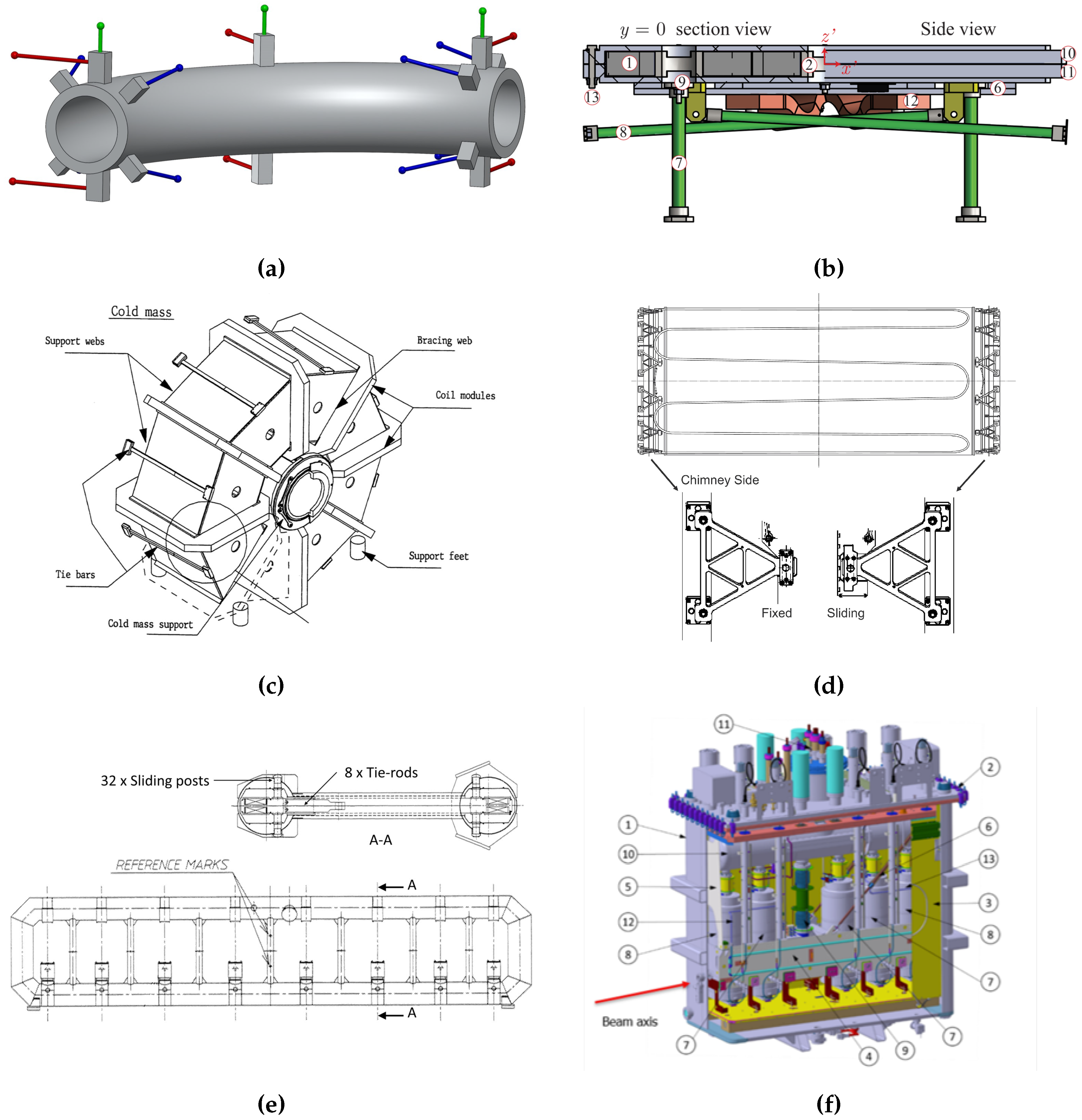
3.1. The “Multi-Post” Architecture and Geometry

The so-called “multi-post” architecture (represented in Figure 1) consists of two or more posts arranged vertically with respect to gravity and radially with respect to the supported body. The posts’ geometry consists of thin-walled cylindrical tubes serially interfaced with the various heat intercepts.
This architecture has been found in the magnet feeder system of ITER (International Thermonuclear Experimental Reactor) [38,39], the cryodipoles and SSS (Short Straight Section) of LHC [42,43], the cryomagnets of RHIC (Relativistic Heavy Ion Collider) [31], the cryomagnets of SSC (Superconducting Super Collider) [35], and the linac cryomodules of LCLS-II (Linac Coherent Light Source II) [37]. While, for the majority of the suspension systems, the posts are placed on the bottom side of the cold mass, in LCLS-II, these are placed on its upper side.

3.2. The “8-Support” Architecture and Geometry

The so-called “8-support” architecture (represented in Figure 2) consists of eight supports arranged in sets of four at each end of the supported body in a symmetric pattern with respect to origin planes (with the origin at the centroid of the supported body). This architecture has been found in both the criss-crossed pattern (Figure 2b) and the non-concurrent version (Figure 2a,b). Two geometries have mainly been found for the supporting element in this suspension system: the rod support (Figure 2a) and the so-called double-band support (Figure 2b,c). The former consists of a rod, eventually split by the heat intercept, while the latter consists of racetrack-shaped elements connected by a linking element, to which the heat intercept is joined. The linking element consists of two pivots that allow a rotation of the bands with respect to each other.
The 8-rod architecture has been found in the quadrupole doublets of the FAIR (Facility for Antiproton and Ion Research) [26,27] and the coils of an MRI at NeuroSpin [48,49]. The 8-double-band suspension system has been found in the analytical paper from the CAS (Chinese Academy of Sciences) [32], the wiggler of TLS (Taiwan Light Source) [24], the wiggler of IHEP (Institute of High Energy Physics of CAS) [22], the coupling solenoid of the MICE [25], and the undulator of SSRF [2,3].
The reasons why, in some designs, the double-band geometry has been preferred over the rod one have not been explicitly reported in the articles found. A possible reason could be related to the easier implementation of the thermalization. Indeed, for it to be effective, it should separate completely the two insulation stages of the suspension elements. This is well implemented in double-band supports. Instead, the use of composite rods would make the thermalization either less effective, because it is applied only to the external cylindrical surface of the rods, or more complex and critical, because of the joint between the two composite rod stages and the metallic thermalization.

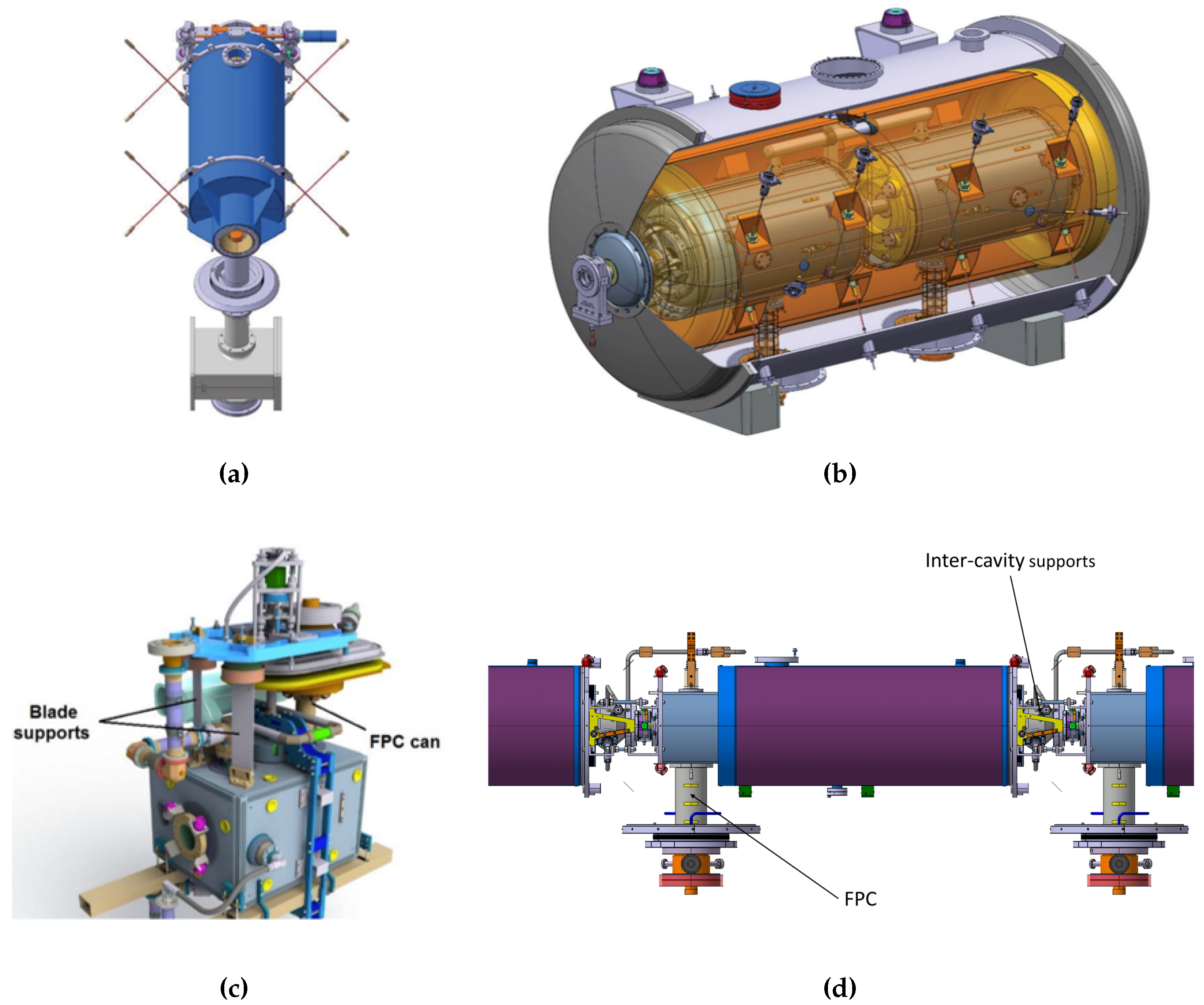
3.3. The Cavity Architecture and Geometry

The cryomodule for cavities often contains a string of them. These can be individually supported or interconnected. Additionally, most designs benefit from the double-walled tube of the FPC (Fundamental Power Coupler) to react to part of the loads, acting as a post.
For the elliptical cavities of the ESS (European Spallation Source) (Figure 3a), a criss-cross 8-rod + 1 pseudo-post architecture has been found [4,5]. In this case, the FPC tube is left free to slide in its axial direction to allow for thermal contractions.
A 22-rod + 2-posts arrangement has been found for the spoke cavities cryomodule of ESS (Figure 3b) [14,15,16]. The 22 rods are distributed on two individual cavities: 8 in the criss-cross “8-support” architecture, for each cavity being used to react lateral and vertical loads; 2 axial rods for each body; and 2 rods interconnecting the two cavities that have been used to control the relative and absolute axial alignment. The FPC is used as a post for each cavity’s partially reacting loads.
The novel architecture chosen for the crab cavities of HL-LHC (High Luminosity LHC) [8,9] is composed of one post and two flexure blades (Figure 3c). In the same way as for other superconducting cavities, the FPC is used as a post support, while two flexure blades have been added to stiffen the system.
An original architecture for cavities has been proposed in the framework of SPL (Superconducting Proton Linac) studies (Figure 3d) [11,12], where the FPC acts as a classic post at one end of the cavity, while two Inter-Cavity Supports (ICSs) have been used as stiffeners. These are left free to slide longitudinally while still transferring the vertical load to the next cavity. The alignment of such architecture could be not trivial on the side of ICS. The studies related to SPL stopped before the experimental phase.

3.4. Other Architectures

Other “exotic” solutions have been found in the literature; these can be associated with the non-standard shape of the cold mass, its dimensions, weight, available space around the assembly, etc.
A 17-rod architecture has been chosen for the transport solenoid of the Mu2e (Muon-to-Electron-conversion) experiment (Figure 4a) [28,29]. In this case, a set of four axial rods has been arranged at each end of the cold mass, and three couples of radial rods have been distributed over three positions of the transport solenoid, to which one vertically spring-loaded rod has been connected.
A 4-rod + 4-post architecture has been proposed for the magnetic density separator studied at UT (University of Twente) (Figure 4b) [19]. The four posts are arranged vertically at each corner of the coil, while the four rods follow a criss-cross pattern.
Highly tailored designs have been used for the suspension system architectures of the magnets of the ATLAS experiment at LHC (grouped in Figure 4): a combination of 16 tie rods and 4 gravity supports have been used for the end-cap toroid magnet (Figure 4c) [50,51,52]; 8 tie rods and 32 cryogenic stops have been arranged over the length of each barrel toroid coil (Figure 4e) [44,45,46]; and 12 triangular struts support the central solenoid at each end (Figure 4d) [33]. The central solenoid support system experiences a thermal gradient between the cold end and the warm end lower than the usual thermal jump of 294–296 K that other supporting systems have to comply with.
The suspension system of the solenoid of the CMS experiment at LHC consists of 30 tie rods: 9 axial rods per each side of the magnet, 4 vertical, and 8 radial [53].
The suspension system of the cold mass within the cryomodule of HIE-ISOLDE (High Intensity and Energy ISOLDE) (Figure 4f) [20,21] consists of two end plates fixed at each end of the support frame and to two separately actuated struts connected to the top plate of the vacuum vessel. Additionally, one tie rod per side is connected on one end to the support frame by means of elastic washers, while the other end is connected by means of a spherical joint with respect to the actuated strut.
The gravity support in the conceptual suspension architecture of DEMO (DEMOnstration power plant) [56], based on the ones designed for ITER, [54,55] consists of an assembly of 21 flexible plates clamped in parallel and spaced apart by spacers (multi-blade support). Supports are placed so that the plates have their minor bending stiffness in the radial direction of the tokamak. While ITER has 18 gravity supports equally distributed at the bottom of the toriodal coils, DEMO is expected to have 16 of them. Additional internal suppports link adjacent toroidal coils, central solenoid, and poloidal field coils.
A four single-band suspension system has been designed built and tested to support a warm bore HTS (High Temperature Superconducting) steering magnet at the VECC (Variable Energy Cyclotron Centre) [17]. Each support can rotate around a pin joint at both ends.
An eight-pillar support architecture have been proposed to suspend a HTS quadrupole magnet for a proton cyclotron beam line studied at CAS [18]. Each composite rod appears to be fixed at each end.

3.5. Intermediate Structural Elements: Common Girder and Space Frame

Some designs include the use of a common girder, as is the case for the quadrupole doublets of FAIR [26,27], or a space frame, as found for the cryomodule of elliptical cavities of ESS [4,5] (see Figure 5). Both the common girder and the spaceframe are used to add a rigid intermediate structure between multiple cold masses and the cryostat. Adjustments of the pose (position and rotation) of the cold masses with respect to each other can be more easily carried out with this sub-assembly outside of the cryostat, as there is more open space for manual operations. Afterwards, the sub-assembly can be slid into the cryostat.
On the one hand, as can be seen from Figure 5a, the common girder becomes, itself, part of the cold mass. Therefore, all the challenges related to the suspension of a cold body with respect to the external room temperature environment remain. Hence, the 8-rod criss-crossed architecture has been chosen.
On the other hand, the space frame (Figure 5b) is closer to the external conditions in the thermal chain; normal adjustable jacks have been distributed along the cryostat to support the space frame. The supports between it and cold masses need to be addressed as well. For instance, the 8-rod criss-crossed architecture has been chosen to suspend the four elliptical cavities within the space frame, while the FPC locks longitudinal movements and is left free to slide along its axis.
Therefore, common girders and space frames do not represent a stand-alone solution. A suspension system similar to the ones mentioned in previous sections is needed. These intermediate structures are mostly used to allow precise alignments of a set of cold masses with larger manipulation freedom while reducing the number of penetrations of the vacuum vessel.

3.6. Other Remarks on Results

Multiple designs with different shaped struts have been studied to support a modular HTS pole coil of wind power generators [58,59,60,61]. The structural mechanical design has not been motivated completely. The addition of a high number of supports, if compared to cold masses of a similar size, allows the redistribution of the high torque. The study of extra stress during the cool-down has not been reported, while it should be critical in these designs since the suspension struts are stiffer than in other reported applications. Additionally, since these suspension systems are related to power generation devices, less care than in other cases has been used to minimize the conduction heat loads. For the reasons just mentioned, these designs have not been added to the summary table.
A conceptual design of a HTS magnet for a particle physics experiment in space have been done in collaboration with CERN [62,63,64]. Space applications do not require vacuum insulation and a classic cryostat. The change in boundary conditions results in an incoherent comparison of the structural supports of this application with other suspension systems described in this review.
The support architecture of references [65,66] could not be classified due to the lack of reported information.
The string “FEA” AND “superconducting” AND “cold mass” AND mechanical AND (∼support OR ∼suspension) -ATLAS -CMS -intitle: “LHC” has been integrated with AND “gantry” to target the research field of rotating machines in medical applications. No relevant results have been found on supporting architectures in this field.

3.7. Materials Used for the Supports

The materials of the supports used in the architectures found are listed below:
  • Metallic materials: Ti-6Al-4V, Ti 5AL 2.5Sn ELI, SS316L, SS 316LN, AISI 304, Inconel® 718;
  • Composites: CFRP (Carbon Fibre Reinforced Polymer), G10, G11, G11CR, UFGE (Unidirectional FibreGlass Epoxy), GFRE (Glass Fibre Reinforced Epoxy), Ultem® 2100, SEl-GFN3 Noryl®.
The choice is usually guided by the ratio of heat conductivity and yield strength (the properties of some materials can be found in references [67,68]), which allow compliance with the requirements of minimal heat loads and proper mechanical resistance. Additionally, materials with low magnetic permeability are preferred over others in the case of interference with the magnetic fields, which is true for almost all applications found.

3.8. Cool-Down Effects and Adjustability

Two main strategies have been identified for managing the cool-down effects in superconducting systems, and these strategies depend heavily on the architecture of the suspension system.
When using eight supports, their symmetric arrangement can generate additional stress in the supporting elements during cool-down. However, this stress is accepted by design to promote a symmetric contraction of the superconducting body (E-SC in Table 2) so that the position of the supported object remains unchanged. Therefore, the alignment strategy involves aligning the superconducting structure at warm temperatures and then relying on self-centering symmetric contraction during cool-down. However, minimal errors may arise due to the imprecise manufacture and assembly of the supports, which can cause them to be positioned asymmetrically.
The use of a “multi-post” architecture allows the system to cool-down without generating extra stress (N-AC in Table 2). As a result, the pose of the magnet can change. Typically, one post is used as a fixed point while the others accommodate the contraction. The misalignment during cool-down cannot be ignored and must be estimated using accurate thermal analysis. The strategy is to intentionally misalign the pose of the suspended object, so that during cool-down it will translate within an acceptable range with respect to the nominal pose.
The N-AC behavior is also a characteristic of some mixed architectures that have been applied to superconducting cavities. For instance, in the case of crab cavities [8,9], the flexure blades have been positioned with the blades tangential to an imaginary cylinder surface that shares the axis with the post. Thus, the radial contraction of the cold mass with respect to the post makes the blades bend in the plane with the least bending stiffness, generating little to no extra stress. The same cool-down effect has been achieved in SPL [11,12] cavities with two ICS that are fixed to one cavity but free to slide and rotate with respect to the adjacent one, thus generating no extra loads during cool-down. The supporting system of the central solenoid of ATLAS [33], with one end fixed and the other able to slide, allows for no build-up of stress during cool-down. Hence, the centroid of the system is displaced longitudinally. In contrast, the presence of spherical bearings at the end of the triangular struts allows the system to preserve the radial position of the axis of the solenoid. The same (N-AC) behavior characterises the suspension system of the HTS steering magnet at VECC, the single-band supports are aligned so that the rotation around each pinned end lays on a radial plane of the cold mass (with respect to the vertical axis).
A potentially optimal solution that could benefit from a symmetric contraction without extra stress (N-SC in Table 2) has been applied to the quadrupole doublets of FAIR [26,27]. This is claimed to be achieved by fine-tuning the geometry of the suspension system so that the contraction of the suspended body is coherent with the contraction of each support in terms of magnitude and direction, resulting in a symmetric contraction without extra stress. In addition to this, the contraction of the supports is fine-tuned by using two materials of different lengths and linear expansion coefficients for each of the eight supports.
The architecture applied to the barrel toroid coils of the ATLAS experiment [44] shows a de-stress behavior during cool-down. In fact, the tie rods have been pre-bent at room temperature to exhibit low to zero stress at cold temperatures. Moreover, the cryogenic stops have been designed to be split into two halves, allowing the cold mass to slide with respect to the vacuum vessel. Furthermore, placing the warm end of the tie rods within the coil envelope could allow the contraction of the coils and the rods to be coherent (both contract toward the horizontal symmetry axis of the coil, see Figure 4e). Therefore, to summarize, the system has been classified as de-stress and symmetric contraction (D-SC in Table 2).
The architecture of MDS (Magnetic Density Separator) [19] due to the four double cantilever posts could present extra stress during cool-down together with an asymmetric contraction in the axial direction of the posts, therefore it has been classified as E-AC. Similarly, the architecture of the tokamak gravity supports of ITER [54,55] and DEMO [56] aims at reducing the incremental stresses exploiting the multi-flexible plate assembly, which offers flexibility in the radial direction. However, some level of additional stress is expected due to cool-down. Additionally, the contraction of the gravity supports in the vertical direction results in an asymmetric movement of the supported body, therefore both have been classified as E-AC.
Adjustability is ensured at different interfaces of the assembly chain that goes from the cold mass to the assumed rigid ground. The following classification is based on the first adjustable link found in this chain. The position of the tuning link in this chain is often related to the support configuration. The “8-support” architecture usually utilizes the regulation of the warm end position of each support to adjust the pose of the suspended object. Thus, the tuning link is at the interface between the vacuum vessel and the support structures (SVI in Table 2). On the other hand, with a “multi-post” architecture, the regulation of the pose of the object is generally done at the interface between the vacuum vessel and the ground (VGI in Table 2). An example of this can be found in the alignment system of the cryomagnets in the LHC [40]. In most cases, if an SVI adjustable link is present, a VGI link is present as well. However, the opposite is not always true. Architectures that have been classified as pure VGI in Table 2 very often do not have an SVI link. Shims are not considered tuning links in this classification.
All of the adjusting systems found in the literature research are used during the initial assembly of the complex, in tuning sessions or after maintenance, and are thus classified as passive (P in Table 2). The suspension architecture of HIE-ISOLDE [20,21] is coupled with an actuated system. However, there is no feedback loop with the position at cold of the suspended body, hence the architecture has been classified as passive.

4. Summary

This section serves as a summary of the literature search conducted and explained in the previous sections. Table 2 gives a summary of the designs found and analyzed, while Table 3 explains the meaning of the parameters used for the classification. Table 4 gives a list of the abbreviations used in the summary table.

5. Discussion

The research on suspension systems for cold masses has resulted in more than 20 applications, ranging from accelerating cavities and cavity strings, wiggler magnets, magnetic density separators, solenoids, quadrupoles, dipoles, feeders, magnets for detectors tokamaks, and MRI. The mass of the suspended body varies from 160–225,000 kg, while the axial length varies from 0.3–25 m. The tokamaks have heights greater than or equal to 24 m, diameters of more than 30 m, and weights more than 23,000 t.
A few HTS applications have been found; in most of the cases these are related to innovative applications, such as wind power generators where the impact of heat loads is minimal if compared to the generated energy, thus less stringent requirements have been accepted. Two HTS magnet applications have been found, and no mention has been made of the necessity of a novel suspension system due to the adoption of HTS instead of standard low temperature superconducting technology.
Nevertheless, three recurrent suspension architectures have been identified. Firstly, the “multi-post” architecture, which is used mainly to suspend slender heavy bodies, for example, the cryomagnets of synchrotrons such as LHC, RHIC and SSC. These magnets are 10–17 m long and have a small diameter with respect to their length. This architecture aims to reduce the vertical sagitta without using many rods that would result in a high number of penetrations of the vacuum vessel. The “8-support” architecture is often used for relatively light or bulky bodies. The cavity architecture is used to support cavities by exploiting the tube wall of the FPC as a post together with extra stiffening structures. Other solutions deviate from the aforementioned due to geometrical reasons, such as the high curvature of the Mu2e transport solenoid, the pancake shape of the magnetic density separation device, or the geometry required by the magnets used for particle detectors. Although they do not represent a standalone suspension solution, intermediate structures, such as common girders and space frames placed between the vacuum vessel and the suspended body, help with the management of modular assemblies and the alignment procedures of multiple cold masses. In these cases, a suspension architecture is still necessary, and the associated challenges remain unchanged.
The common behaviors with respect to the cool-down process have been classified. Depending on the architecture, extra stress can develop in the supports in exchange for a more accurate pose (position and orientation) of the body after the cool-down. In different architectures, a reproducible asymmetric contraction of the system has been accepted in exchange for low to zero extra stress on the supports. Although more complex, a possible optimal solution has been identified in the architecture of FAIR; this could be based on the careful tuning of the materials and geometry of the suspension system to achieve both desirable cool-down characteristics: a symmetric contraction without extra stress.
The materials found in suspension systems belong to either metallic or composite classes. The choice is guided by the compliance with the requirements of mechanical resistance and minimization of heat loads to the cold mass. The most common metallic materials used include titanium alloys, stainless steel alloys, and nickel–chromium alloys. Composites such as glass-fiber-reinforced epoxy or carbon-fiber-reinforced polymers have also been utilized. Although not explicitly mentioned in the articles subject to this review, an analysis of Table 2 highlights a possible correlation between the shape of the support and its material. Indeed, almost all rods have been built from metallic materials while all double-bands architectures exploit composites. An exception is represented by the G11 rods of the magnetic density separator studied at UT and G10 pillars studied for the HTS quadrupole studied at CAS.
Two recurrent solutions for adjustability have been identified based on the position of a tuning link in the chain of errors. This link can be found placed between the cold mass supports and the vacuum vessel (SVI) and/or between the vacuum vessel and the rigid ground (VGI).
All proposed solutions have been designed to function nominally, reacting mostly dead weight or electromagnetic forces in a static environment (i.e., no relative rotation with respect to the gravity vector). Generally, transportation loads, seismic loads, and catastrophic failures, such as destructive quenching, have been considered. Therefore, most of the solutions have been verified for mechanical resistance in directions different from those on which the nominal load is acting. The misalignment of the cold mass due to the dead weight is constant and can be compensated once and for all during assembly, leaving no constrain on the rigidity of the system. Therefore, even though the position of the cold mass is a requirement of the supporting system, its design simply follows a trade-off between heat loads and mechanical resistance.
In contrast, the passive compensation of misalignment due to dead weight at one orientation of the body (with respect to gravity) will negatively impact other orientations. Therefore, a change of paradigm is necessary: the design trade-off should be between heat loads and the overall stiffness of the architecture, which is usually more restrictive than mechanical resistance alone. Hence, there is a space for researching the architectures tailored to work on rotating machines. Nevertheless, most support architectures are deemed conceptually applicable to a rotating body although requiring R&D.
The suspension systems classified as SVI appear to be often designed with bilateral fixtures such as rod ends and spherical bearings and, therefore, would be directly applicable to a rotating body. In contrast, VGI support systems’ simplified designs usually exploit unilateral fixtures such as spherical washers. Hence, these are not directly applicable to rotating bodies without additional R&D. A regulation system at the SVI for the pose of a body supported by posts is expected to raise the level of complexity of the cryostat assembly and decrease the performances (stiffness) of the tuning system itself because of the serial combination of linear guides and pivots.
Except for the suspension system of ISOLDE (Isotope Separator On Line DEvice), all other architectures found are not exactly constrained; they are, indeed, over-constrained. However, the motorized struts of ISOLDE allows for the adjustment of only four degrees of freedom of the cold mass. Therefore, a detailed solution for the support and complete alignment system of a body with an exact number of constrains has not been found in this literature review.

6. Conclusions

The literature review of suspension systems for superconducting bodies, or cold masses in general, has identified recurring design patterns. A classification based on the system’s geometrical architecture, cool-down behavior, and adjustability has been presented. General design characteristics, such as the dimensions and weight of the suspended body, materials used for the supports, and current status, have been summarized in a table. A conceptual analysis of the applicability of these support architectures to rotating machines has been provided, highlighting the fact that none of the designs found have been specifically designed for this purpose and indicating a possible direction for future research. Furthermore, a detailed solution for the support and complete alignment system of a superconducting element with an exact number of constrains has been highlighted as a subject where knowledge is missing. Further research in these directions could be valuable, especially in the case of medical superconducting machines for hadron therapy.

Author Contributions

Conceptualization L.P., L.D., D.P., A.R. and S.U. Formal analysis, L.P.; Investigation, L.P.; Methodology, L.P. and L.D.; Visualization, L.P.; Writing—original draft, L.P.; Writing—review and editing, L.D., D.P., A.R., T.T. and S.U.; Supervision, L.D., D.P. and S.U.; Project administration, L.D., D.P., A.R., T.T. and S.U.; Funding acquisition, T.T. All authors have read and agreed to the published version of the manuscript.

Funding

This project has received funding from the European Union’s Horizon 2020 Research and Innovation programme under HITRIplus grant agreement No 101008548. This study has received support from the CERN Budget for Knowledge Transfer to Medical Applications, in the frame of the Next Ion Medical Machine Study. This project is supported by the Latvian Council of Science under grant agreement VPP-IZM-CERN-2022/1-0001.

Institutional Review Board Statement

Not applicable.

Informed Consent Statement

Not applicable.

Data Availability Statement

Not applicable.

Conflicts of Interest

The authors declare no conflict of interest.

References

  1. Martín-Martín, A.; Orduna-Malea, E.; Thelwall, M.; López-Cózar, E.D. Google Scholar, Web of Science, and Scopus: A systematic comparison of citations in 252 subject categories. J. Inf. 2018, 12, 1160–1177. [Google Scholar] [CrossRef]
  2. Liu, Y.; Wang, J.; Wang, L.; Sun, S.; Wang, S.; Yin, L. Design of cold mass supports for a superconducting undulator prototype at SINAP. IEEE Trans. Appl. Supercond. 2014, 25, 4101004. [Google Scholar] [CrossRef]
  3. Wang, L.; Liu, Y.; Guo, X.; Wang, S.; Li, M.; Sun, S. Development of a Test Cryostat for a Superconducting Undulator Prototype at the SSRF. IEEE Trans. Appl. Supercond. 2021, 31, 9500105. [Google Scholar] [CrossRef]
  4. Darve, C.; Bosland, P.; Devanz, G.; Olivier, G.; Renard, B.; Thermeau, J.P. The ESS elliptical cavity cryomodules. AIP Conf. Proceedings. Am. Inst. Phys. 2014, 1573, 639–646. [Google Scholar]
  5. Olivier, G.; Thermeau, J.; Bosland, P.; Darve, C. Ess cryomodules for elliptical cavities. In Proceedings of the 16th International Conference on RF Superconductivity, Paris, France, 23–27 September 2013. [Google Scholar]
  6. European Spallation Source. ESS Installs First Two Cryomodules in the Linac. Available online: https://europeanspallationsource.se/article/2023/03/15/ess-installs-first-two-cryomodules-linac (accessed on 20 February 2023).
  7. Monaco, L.; Bellandi, A.; Bertucci, M.; Bignami, A.; Bosotti, A.; Chen, J.; Michelato, P.; Paparella, R.; Sertore, D.; Pagani, C.; et al. Fabrication and treatment of the ESS medium beta prototype cavities. In Proceedings of the 8th International Particle Accelerator Conference, Copenhagen, Denmark, 14–19 May 2017; pp. 1003–1006. [Google Scholar]
  8. Carra, F.; Apeland, J.; Calaga, R.; Capatina, O.; Capelli, T.; Verdú-Andrés, S.; Zanoni, C. Assessment of thermal loads in the CERN SPS crab cavities cryomodule1. J. Phys. Conf. Ser. 2017, 874, 012005. [Google Scholar] [CrossRef]
  9. Jones, T.; Burt, G.; Artoos, K.; Calaga, R.; Capatina, O.; Capelli, T.; Sosin, M.; Swieszek, J.; Zanoni, C. Development of a Novel Supporting System for High Luminosity LHC SRF Crab Cavities. In Proceedings of the 18th International Conference on RF Superconductivity, Lanzhou, China, 17–21 July 2017; JACOW: Geneva, Switzerland, 2018; pp. 304–308. [Google Scholar]
  10. Pattalwar, S.; Burt, G.; Capatina, O.; Hall, B.; Jones, T.; May, A.; McIntosh, P.; Nicol, T.; Templeton, N.; Wheelhouse, A.; et al. Key Design Features of Crab-Cavity Cryomodule for HiLumi LHC. In Proceedings of the 5th International Particle Accelerator Conference, Dresden, Germany, 15–20 June 2014; pp. 2580–2582. Available online: https://cds.cern.ch/record/2003149/files/wepri045.pdf (accessed on 20 February 2023).
  11. Azevedo, P. SPL Short Cryomodule Design. In Indico, SPL Internal Meeting, CERN; CERN: Geneva, Switzerland, 2012. [Google Scholar]
  12. Parma, V.; Van Weelderen, R.; Schirm, K.; Chambrillon, J.; Vande Craen, A.; Vandoni, G.; Montesinos, E.; Capatina, O.; Bonomi, R. Status of the Superconducting Proton Linac (SPL) Cryo-Module. In Proceedings of the 16th International Conference on RF Superconductivity, Paris, France, 23–27 September 2013; pp. 345–348. [Google Scholar]
  13. Atieh, S.; Weingarten, W.; Arnau Izquierdo, G.; Renaglia, T.; Capatina, O.; Tardy, T.; Aviles Santillana, I.; Valverde Alonso, N. Mechanical Design and Fabrication Studies for SPL Superconducting RF Cavities. In Proceedings of the 2nd International Particle Accelerator Conference, San Sebastian, Spain, 4–9 September 2011; pp. 199–201. [Google Scholar]
  14. Reynet, D.; Brault, S.; Duthil, P.; Duchesne, P.; Olry, G.; Gandolfo, N.; Rampnoux, E.; Bousson, S. Design of the ESS Spoke cryomodule. In Proceedings of the SRF 2013, Paris, France, 23–27 September 2013; pp. 357–360. [Google Scholar]
  15. Bousson, S.; Darve, C.; Duthil, P.; Elias, N.; Molloy, S.; Reynet, D.; Thermeau, J.P. The ESS spoke cavity cryomodules. AIP Conf. Proceedings. Am. Inst. Phys. 2014, 1573, 665–672. [Google Scholar]
  16. Duthil, P.; Reynet, D.; Olry, G.; Brault, S.; Duchesne, P.; Gandolfo, N.; Rampnoux, E.; Darve, C.; Ellas, N. Design and Prototyping of the Spoke Cyromodule for ESS. In Proceedings of the HB2016, Malmö, Sweden, 3–8 July 2016; pp. 416–421. [Google Scholar]
  17. Bhunia, U.; Agrawal, A.; Roy, A.; Nandi, C.; Khare, V.; Thakur, S.; Dey, M.; Bandyopadhyay, A. Development and performance evaluation of a conduction-cooled warm bore HTS steering magnet. Physica C 2023, 604, 1354191. [Google Scholar] [CrossRef]
  18. Zhang, J.; Song, Y.; Zhang, W.; Jiang, F. Magnetic and thermal design of HTS quadrupole magnet for newly developed superconducting proton cyclotron beam line. J. Supercond. Nov. Magn. 2019, 32, 529–538. [Google Scholar] [CrossRef]
  19. Kosse, J.; Wessel, W.; Zhou, C.; Dhallé, M.; Tomás, G.; Krooshoop, H.; Ter Brake, H.; Ten Kate, H. Mechanical design of a superconducting demonstrator for magnetic density separation. Supercond. Sci. Technol. 2021, 34, 115019. [Google Scholar] [CrossRef]
  20. Kadi, Y.; Fraser, M.A.; Papageorgiou-Koufidou, A. HIE-ISOLDE: Technical Design Report for the Energy Upgrade; CERN Yellow Reports: Monographs; CERN: Geneva, Switzerland, 2018. [Google Scholar] [CrossRef]
  21. Delruelle, N.; Leclercq, Y.; Pirotte, O.; Ramos, D.; Tibaron, P.; Vandoni, G.; Williams, L. The high Beta cryo-modules and the associated cryogenic system for the HIE-ISOLDE upgrade at CERN. AIP Conf. Proc. 2014, 1573, 811–818. [Google Scholar]
  22. Xu, M.F.; Zhang, X.Z.; Ye, R.; Chen, F.S.; Yang, X.C.; Zhao, T.X.; Li, S.P.; Sun, X.J.; Sun, L.R.; Ma, C.C.; et al. Design, assembly, and pre-commissioning of cryostat for 3W1 superconducting wiggler magnet. Nucl. Sci. Tech. 2020, 31, 113. [Google Scholar] [CrossRef]
  23. Hwang, C.; Chang, C.; Chen, H.; Lin, F.; Fan, T.; Huang, M.; Jan, J.; Hsu, K.; Chen, J.; Hsu, S.; et al. Superconducting wiggler with semi-cold beam duct at Taiwan light source. Nucl. Instruments Methods Phys. Res. Sect. Accel. Spectrometers, Detect. Assoc. Equip. 2006, 556, 607–615. [Google Scholar] [CrossRef]
  24. Chen, H.; Hwang, C.; Chang, C.; Jan, J.; Lin, F.; Huang, M.; Fan, T. Design of mechanical structure and cryostat for IASW superconducting wiggler at NSRRC. In Proceedings of the 2007 IEEE Particle Accelerator Conference (PAC), Albuquerque, NM, USA, 25–29 June 2007; pp. 374–376. [Google Scholar]
  25. Wang, L.; Wu, H.; Li, S.; Guo, X.; Pan, H.; Zheng, S.X.; Green, M.A. Design and analysis of a self-centered cold mass support for the MICE coupling magnet. IEEE Trans. Appl. Supercond. 2011, 21, 2259–2262. [Google Scholar] [CrossRef]
  26. Fischer, E.; Schnizer, P.; Sugita, K.; Meier, J.P.; Mierau, A.; Spiller, P.; Kester, O.; Khodzhibagiyan, H.; Trubnikov, G. Superconducting quadrupole module system for the sis100 synchrotron. In Proceedings of the Russian Particle Accelerator Conference 2012, Saint-Petersburg, Russia, 24–28 September 2012; pp. 143–145. [Google Scholar]
  27. Meier, J.; Bleile, A.; Fischer, E.; Hess, G.; Macavei, J.; Spiller, P. Cryo-technical design aspects of the superconducting SIS100 quadrupole doublet modules. AIP Conf. Proceedings. Am. Inst. Phys. 2014, 1573, 1519–1526. [Google Scholar]
  28. Ambrosio, G.; Andreev, N.; Cheban, S.; Coleman, R.; Dhanaraj, N.; Evbota, D.; Feher, S.; Kashikhin, V.; Lamm, M.; Lombardo, V.; et al. Challenges and design of the transport solenoid for the Mu2e experiment at Fermilab. IEEE Trans. Appl. Supercond. 2013, 24, 4101405. [Google Scholar] [CrossRef]
  29. Lopes, M.; Ambrosio, G.; Badgley, K.E.; Bradascio, F.; Brandt, J.; Evbota, D.; Hocker, A.; Lamm, M.; Lombardo, V.; Miller, J.; et al. Mu2e transport solenoid cold-mass alignment issues. IEEE Trans. Appl. Supercond. 2017, 27, 4500405. [Google Scholar] [CrossRef]
  30. Wanderer, P.; Muratore, J.; Anerella, M.; Ganetis, G.; Ghosh, A.; Greene, A.; Gupta, R.; Jain, A.; Kahn, S.; Kelly, E.; et al. Construction and testing of arc dipoles and quadrupoles for the Relativistic Heavy Ion Collider (RHIC) at BNL. Proc. Part. Accel. Conf. 1995, 2, 1293–1297. [Google Scholar]
  31. Sondericker, J.; Wolf, L. Alternative concepts for structurally supporting the cold mass of a superconducting accelerator magnet. In Supercollider 3; Nonte, J., Ed.; Springer: Boston, MA, USA, 1991; pp. 175–189. [Google Scholar] [CrossRef]
  32. Li, L.; Wang, Q.; Zhao, B.; Ni, Z.; Cui, C.; Wang, H. Theoretical model of a cold mass strap suspension system for superconducting magnets. IEEE Trans. Appl. Supercond. 2011, 21, 3640–3645. [Google Scholar] [CrossRef]
  33. Yamamoto, A.; Makida, Y.; Ruber, R.; Doi, Y.; Haruyama, T.; Haug, F.; Ten Kate, H.; Kawai, M.; Kondo, T.; Kondo, Y.; et al. The ATLAS central solenoid. Nucl. Instruments Methods Phys. Res. Sect. A 2008, 584, 53–74. [Google Scholar] [CrossRef]
  34. Devred, A.; Chapman, M.; Cortella, J.; Desportes, A.; DiMarco, J.; Kaugerts, J.; Schermer, R.; Tompkins, J.; Turner, J.; Cottingham, J.; et al. Quench Characteristics of Full-Length SSC R&D Dipole Magnets; Advances in Cryogenic Engineering, Volume 35; Springer: Boston, MA, USA, 1990. [Google Scholar] [CrossRef]
  35. Nicol, T.; Niemann, R.; Gonczy, J. SSC magnet cryostat suspension system design. In Advances in Cryogenic Engineering; Springer: A Cryogenic Engineering Conference Publication, Volume 33; Springer: Boston, MA, USA, 1988; pp. 227–234. [Google Scholar] [CrossRef]
  36. Galayda, J. The LCLS-II: A High Power Upgrade to the LCLS; SLAC National Accelerator Lab.: Menlo Park, CA, USA, 2018. [Google Scholar]
  37. Peterson, T.; Arkan, T.; Ginsburg, C.; He, Y.; Kaluzny, J.; McGee, M.; Orlov, Y. LCLS-II 1.3 GHz cryomodule design-modified tesla-style cryomodule for CW operation. In Proceedings of the 17th International Conference on RF Superconductivity, Whistler, Canada, 13–18 September 2015; pp. 1417–1421. [Google Scholar]
  38. Lu, K.; Song, Y.; Niu, E.; Zhou, T.; Wang, Z.; Chen, Y.; Zhu, Y. Evolution of the design of cold mass support for the ITER magnet feeder system. Plasma Sci. Technol. 2013, 15, 196. [Google Scholar] [CrossRef]
  39. Zhu, Y.; Song, Y.; Zhang, Y.; Wang, Z. Conceptual design and analysis of cold mass support of the CS3U feeder for the ITER. Plasma Sci. Technol. 2013, 15, 599. [Google Scholar] [CrossRef]
  40. Dwivedi, J.; Kumar, A.; Parma, V.; Goswami, S.; Madhumurthy, V.; Soni, H. The Alignment Jacks of the LHC Cryomagnets. In Proceedings of the EPAC 2004, Lucerne, Switzerland, 5–9 July 2004; pp. 1687–1689. [Google Scholar]
  41. Castoldi, M.; Parma, V.; Pangallo, M.; Vandoni, G. Thermal Performance of the Supporting System for the Large Hadron Collider (LHC) Superconducting Magnets. In Proceedings of the Joint Cryogenic Engineering Conference and International Cryogenic Materials Conference, LHC project report 335, Montreal, Canada, 12–16 July 1999. [Google Scholar]
  42. Seyvet, F.; Jeanneret, J.B.; Poncet, A.; Tommasini, D.; Beauquis, J.; Cano, E.F.; Wildner, E. Improvement of the geometrical stability of the LHC cryodipoles when blocking the central support post. In Proceedings of the 2005 Particle Accelerator Conference, Knoxville, TN, USA, 16–20 May 2005; pp. 2675–2677. [Google Scholar]
  43. Mathieu, M.; Parma, V.; Renaglia, T.; Rohmig, P.; Williams, L. Supporting systems from 293 K to 1.9 K for the Large Hadron Collider (LHC) cryo-magnets. Adv. Cryog. Eng. 1998, 43, 427–434. [Google Scholar]
  44. Dudarev, A.; Rabbers, J.; Berriaud, C.; Junker, S.; Pengo, R.; Ravat, S.; Deront, L.; Sbrissa, E.; Olesen, G.; Arnaud, M.; et al. First full-size ATLAS barrel toroid coil successfully tested up to 22 kA at 4 T. IEEE Trans. Appl. Supercond. 2005, 15, 1271–1274. [Google Scholar] [CrossRef]
  45. Mayri, C.; Berriaud, C.; Cazaux, S.; Dudarev, A.; Foussat, A.; Pabot, Y.; Rey, J.; Reytier, M.; Ten Kate, H.; Sun, Z.; et al. Suspension system of the barrel toroid cold mass. IEEE Trans. Appl. Supercond. 2006, 16, 525–528. [Google Scholar] [CrossRef]
  46. Badiou, J.; Beltramelli, J.; Baze, J.; Belorgey, J. ATLAS Barrel Toroid: Technical Design Report; CERN cds; CERN: Geneva, Switzerland, 1997. [Google Scholar] [CrossRef]
  47. Boulant, N.; Quettier, L. Commissioning of the Iseult CEA 11.7 T whole-body MRI: Current status, gradient–magnet interaction tests and first imaging experience. Magn. Reson. Mater. Phys. Biol. Med. 2023, 36, 175–189. [Google Scholar] [CrossRef]
  48. Nunio, F.; Berriaud, C.; Bredy, P.; Schild, T.; Scola, L.; Tellier, O.; Vedrine, P. Mechanical design of the Iseult 11.7 T whole body MRI magnet. IEEE Trans. Appl. Supercond. 2010, 20, 760–763. [Google Scholar] [CrossRef]
  49. Vedrine, P.; Maksoud, W.A.; Aubert, G.; Beaudet, F.; Belorgey, J.; Bermond, S.; Berriaud, C.; Bredy, P.; Bresson, D.; Donati, A.; et al. Latest progress on the Iseult/INUMAC whole body 11.7 T MRI magnet. IEEE Trans. Appl. Supercond. 2011, 22, 4400804. [Google Scholar] [CrossRef]
  50. Baynham, D.E.; Butterworth, J.; Carr, F.; Courthold, M.; Cragg, D.; Densham, C.; Evans, D.; Holtom, E.; Robertson, S.; Sole, D.; et al. Engineering design optimisation of the superconducting end cap toroid magnets for the ATLAS experiment at LHC. IEEE Trans. Appl. Supercond. 1999, 9, 856–859. [Google Scholar] [CrossRef]
  51. Baynham, D.; Carr, F.; Holtom, E.; Buskop, J.; Dudarev, A.; Vandoni, G.; Ruber, R.; Foussat, A.; Losasso, M.; Benoit, P.; et al. ATLAS end cap toroid final integration, test and installation. IEEE Trans. Appl. Supercond. 2008, 18, 391–394. [Google Scholar] [CrossRef]
  52. ATLAS, Magnet Project collaboration, End-Cap Toroid Group. ATLAS End-Cap Toroids: Technical Design Report; CERN cds; CERN: Geneva, Switzerland, 1997. [Google Scholar] [CrossRef]
  53. Levesy, B.; Gerwig, H.; Kircher, F.; Reytier, M. Design and test of the titanium alloy tie rods for the CMS coil suspension system. IEEE Trans. Appl. Supercond. 2002, 12, 403–406. [Google Scholar] [CrossRef]
  54. Mitchell, N.; Devred, A.; Libeyre, P.; Lim, B.; Savary, F. The ITER magnets: Design and construction status. IEEE Trans. Appl. Supercond. 2011, 22, 4200809. [Google Scholar] [CrossRef]
  55. Liao, M.; Li, P.; Hou, B.; Yang, S.; Fu, Y.; Gallix, R. Prototype engineering test platform of ITER magnet gravity support. Plasma Sci. Technol. 2013, 15, 192. [Google Scholar] [CrossRef]
  56. Corato, V.; Vorpahl, C.; Sedlak, K.; Anvar, V.; Bennet, J.; Biancolini, M.; Bonne, F.; Bonifetto, R.; Boso, D.; Brighenti, A.; et al. The DEMO magnet system–Status and future challenges. Fusion Eng. Des. 2022, 174, 112971. [Google Scholar] [CrossRef]
  57. Weisend, J., II. Cryostat Design; Springer: Berlin/Heidelberg, Germany, 2016. [Google Scholar] [CrossRef]
  58. Lee, J.; Seo, G.; Mun, J.; Park, M.; Kim, S. Thermal and mechanical design for refrigeration system of 10 MW class HTS wind power generator. IEEE Trans. Appl. Supercond. 2020, 30, 5201905. [Google Scholar] [CrossRef]
  59. Tuvdensuren, O.; Go, B.; Sung, H.; Park, M. Design of an HTS module coil for a 750 kW-class superconducting wind power generator. J. Phys. Conf. Ser. 2019, 1293, 012077. [Google Scholar] [CrossRef]
  60. Tuvdensuren, O.; Sung, H.; Go, B.; Le, T.; Park, M.; Yu, I. Structural design and heat load analysis of a flux pump-based HTS module coil for a large-scale wind power generator. J. Phys. Conf. Ser. 2018, 1054, 012084. [Google Scholar] [CrossRef]
  61. Go, B.; Sung, H.; Park, M.; Yu, I. Structural design of a module coil for a 12-MW class HTS generator for wind turbine. IEEE Trans. Appl. Supercond. 2017, 27, 5202405. [Google Scholar] [CrossRef]
  62. Dam, M.; Battiston, R.; Burger, W.; Carpentiero, R.; Chesta, E.; Iuppa, R.; Rijk, G.; Rossi, L. Conceptual design of a high temperature superconducting magnet for a particle physics experiment in space. Supercond. Sci. Technol. 2020, 33, 044012. [Google Scholar] [CrossRef]
  63. Dam, M.; Burger, W.; Carpentiero, R.; Chesta, E.; Iuppa, R.; Rijk, G.; Rossi, L. Design and modeling of AMaSED-2: A high temperature superconducting demonstrator coil for the space spectrometer ARCOS. IEEE Trans. Appl. Supercond. 2022, 32, 4500105. [Google Scholar] [CrossRef]
  64. Dam, M.; Burger, W.; Carpentiero, R.; Chesta, E.; Iuppa, R.; Kirby, G.; Rijk, G.; Rossi, L. Manufacturing and testing of AMaSED-2: A no-insulation high-temperature superconducting demonstrator coil for the space spectrometer ARCOS. Supercond. Sci. Technol. 2022, 36, 014007. [Google Scholar] [CrossRef]
  65. Guo, X.L.; Wang, L.; Wang, J.; Wang, S.; Liu, Y.; Sun, S. Thermal and mechanical analysis on the cold mass support assembly of test cryomodule for IMP ADS-injector-II. AIP Conf. Proc. Am. Inst. Phys. 2014, 1573, 1341–1348. [Google Scholar]
  66. Yuan, J.; Ma, L.; He, Y.; Zhang, B.; Zhang, J.; Sun, G. Alignment and Deformation of the Cryostat in the CADS Injector II. In Proceedings of the 15th International Workshops on Accelerator Alignment, Fermilab, Batavia, NY, USA, 8–12 October 2018. [Google Scholar]
  67. Duthil, P. Material properties at low temperature. arXiv 2015, arXiv:1501.07100. [Google Scholar]
  68. National Institute of Standards and Technologies. Properties of Solid Materials from Cryogenic to Room-Temperatures. Available online: https://trc.nist.gov/cryogenics/materials/materialproperties.htm (accessed on 20 February 2023).
Figure 1. Example of the “multi-post” architecture for the suspension system of superconducting bodies. (a) represents the lateral view of three of the five supporting elements originally designed to support the SSC cryodipoles (reproduced with permission from T. H. Nicol et al. SSC Magnet Cryostat Suspension System Design; published by Springer Nature, 1988 [35]). (b) illustrates the arrangement of three supporting elements for the cryodipoles of the LHC.
Machines 11 00929 g001
Figure 2. Example of the “8-support” architecture for the suspension system of superconducting bodies. In (a), one can see a schematization of the eight rods supporting the main coil of NeuroSpin MRI (Magnetic Resonance Imaging); (b) shows the eight-double-band suspension of the coupling solenoid of the MICE (Muon Ionization Cooling Experiment) experiment [25] (Copyright 2011, by IEEE. Reproduced with permission); in (c), the eight-double-band supports of the superconducting undulator developed at the SSRF (Shanghai Synchrotron Radiation Facility) [2] are represented (Copyright 2015, by IEEE. Reproduced with permission).
Machines 11 00929 g002
Figure 3. Example of cavity architectures. In (a), the suspension architecture of elliptical cavities of ESS [4] is represented; (b) is a representation of the supports of spoke cavities of ESS [15]; (c) illustrates the architecture of supports of crab cavities for the HL-LHC [8]; (d) is a drawing of the support architecture of SPL.
Machines 11 00929 g003
Figure 4. Examples of “exotic” suspension architectures. In (a), one can see the 14 rods + 3 spring (green) scheme of the suspension system of the transport solenoid of the Mu2e experiment (the original image can be found in reference [29]); (b) shows the support architecture for a magnetic density separator [19]; in (c), one can see the 16 tie bars and 4 gravity supports of the end cap toroid magnets [52]; in (d), the 24 triangle suspension system of the central solenoid is illustrated (reproduced with permission from A. Yamamoto et al., The ATLAS central solenoid; published by Elsevier, 2008 [33]); (e) shows the 8 tie rods and 32 cryogenic stops of a single barrel toroid coil of ATLAS [44]. In (f), the suspension system within HIE-ISOLDE cryomodule is represented [20].
Machines 11 00929 g004
Figure 5. Example of multiple sub-assemblies common cryostat suspension architectures. In (a), one can see the common girder of the quadruple doublets of FAIR Synchrotron [26]; (b) shows the space frame that supports four elliptical cavities of ESS (reproduced with permission from Darve, Christine; Bosland, Pierre, The ESS elliptical cavity cryomodules; published by AIP Publishing, 2014 [4]).
Machines 11 00929 g005
Table 1. List of keywords used in the search and their descriptions.
KeywordDescription
FEAFilters results in which the suspension system has been analyzed using Finite Element Analysis.
superconductingSets the search field to superconducting technologies.
cold massHighlights the interest in cold mass supports.
mechanicalFilters for mechanical analysis rather than just general physics analysis.
supportSets the search field to the supports of a superconducting element.
suspensionSynonym for “support.”
ATLASAvoids repeated articles in the results citing one of the most well-known physics experiments (included manually afterwards).
CMSAvoids repeated articles in the results citing one of the most well-known physics experiments (included manually afterwards).
LHCAvoids the many publications related to LHC supports (included manually afterwards).
Table 2. Summary table of the researched suspension system for superconducting elements. The main characteristics have been reported and classified following the nomenclature reported as notes below the table. Results have been ordered by increasing weight of the cold mass.
Ref.ProjectElementSC MaterialMassL1 aL2 bArchitectureMaterialCool-Down cApplicability dAdjustability ePublicationStatus f
kg m m
[2,3]SSRFMagnetNbTi wire160 0.8 0.8  *8 bandsCFRPE-SCpossibleSVI-P-R2014, 2021op.
[4,5,6,7]ESSCavityNb sheets210 1.5 ca. 0.45  *8 rods +
1 post ***
Ti-6Al-4V (rod) +
power-coupler
E-SCpossibleSVI-P-R2013, 2014
2017 2023
const.
[8,9,10]HL-LHCCavityNb bulk250 0.7  *1 *2 blades +
1 post
SS 316L +
power-coupler
N-ACpossibleVGI-P-NR *2014, 2017
2018
dev.
[11,12,13]SPLCavityNb bulk 1.5  * 0.45  *2 ICS +
1 post
N-ACpossibleVGI-P-NR *2011, 2012
2014
ND
[6,14,15,16]ESS (spoke)CavityNb sheets 1.92 0.6  *22 rods +
2 posts
Ti-6Al-4V (rod) +
power-coupler
NDpossibleSVI-P-R2013, 2014,
2016, 2017
const.
[17]VECCMagnetBi-2223 wire 0.4 0.4  *4 bandsG10N-ACdiscouragedVGI-P-NR2023op.
[18]CASMagnetYBCO tape 0.4  * 0.3  *8 pillarsG10E-SCpossibleSVI-P-R2019dev.
[19]MDS (UT)MagnetNbTi wire520 1.54 1 *4 posts +
4 rods
G11E-AC *possibleNot relevant2021dev.
[20,21]HIE-ISOLDEFrameCu sheets
Nb coating
85021 *2 rods +
2 plates
N-ACdiscouragedSVI-P-NR2014, 2018op.
[22]IHEPMagnet 1400 1.4 ca. 0.2  *8 bandsT300 (CFRP)E-SCpossibleSVI-P-R2020op.
[23,24]TLSMagnetNbTi wire 1.4 0.2  *8 bandsUFGEE-SCpossibleSVI-P-R2006, 2007op.
[25]MICEMagnetNbTi wire1600 0.3 1.7 8 bandsUFGEE-SCpossibleSVI-P-R2011op.
[26,27]FAIRFrameNbTi wire 5.56 0.7  *8 rodsTi-6Al-4V +
AISI 304
N-SCpossibleVGI-P-NR *2012, 2014const.
[28,29]Mu2eMagnetNbTi wire 6.7 0.8  *3 springs +
14 rods
Inconel® 718NDpossibleSVI-P-R *2013, 2017const.
[30,31]RHICMagnetNbTi wire3605 9.4 0.3  *3 postsUltem® 2100 or
SEl-GFN3 Noryl®
N-ACpossibleVGI-P-NR *1991, 1995op.
[32]CASMagnet 4000 1.4 2.2 8 bands E-SCpossible 2011res.
[33]ATLAS CSMagnetNbTi wire4700 5.3 2.6 24 strutsGFREN-ACpossibleSVI-P-R2007op.
[34,35]SSCMagnetNbTi wire770017 0.3  *5 postsG11CRN-ACpossibleVGI-P-NR *1988, 1990cancelled
[36,37]LCLS-IIHE pipeNb sheets860012 0.6  *3 posts
(hung)
G10N-AC *discouragedSVI-P-NR +
VGI-P-NR
2015, 2018op.
[38,39]ITERFeeder 10,000 ca. 10 ca. 0.5  *2 postsSS 316LNN-AC *possibleNot relevant2013const.
[40,41,42,43]LHCMagnetNbTi wire25,000 **16  ** 0.6 3 posts **GFREN-ACpossibleVGI-P-NR1998, 1999
2004, 2005
op.
[44,45,46]ATLAS BTMagnetNbTi wire45,0002558 rods +
32 stops
Ti 5Al 2.5 Sn ELI
GFRE
D-SC *possibleVGI-P-R1997, 2005
2006
op.
[47,48,49]NeuroSpinMagnetNbTi wire132,000548 rodsTi-6Al-4VE-SCpossibleSVI-P-R *2010, 2011
2023
comm.
[50,51,52]ATLAS ECTMagnetNbTi wire160,0005 10.7 20 rodsstainless steelNDpossibleSVI-P-R1999, 2008op.
[53]CMS CSMagnetNbTi wire225,000 12.5 6 ca.30 rodsTi 5Al 2.5Sn ELIE-SCpossibleSVI-P-R *2002op.
[54,55]ITERMagnetNb3Sn and
NbTi
23 × 10 6 243018 multi-
blades
stainless steelE-ACpossibleVGI-P-NR *2011, 2013const.
[56]DEMOMagnetNb3Sn, NbTi
and RE-123
36 ca.45 ca.16 multi-
blades
stainless steelE-ACpossibleVGI-P-NR *2022dev.
a: Axial length of the supported body, (curvilinear for Mu2e project). b: Second major length of the supported body. c: Cool-down effect classification: Extra stress can arise as a consequence of cool-down (E). No extra stress (N). De-stress (D). Symmetric Contraction, the pose (position and rotation) of the cold mass does not change (SC). Asymmetric Contraction, the pose changes (AC). Not easily Deducible (ND). d: Applicability to a rotating machine. e: Adjustability classification: The pose of the cold mass is adjusted acting at the Suspension system to Vacuum vessel Interface (SVI). Vacuum vessel to Ground Interface (VGI). The alignment is Passive (P) if not actuated or Active (A). The adjustable system is applicable to rotating bodies (R) or not applicable (NR) mainly due to unilateral fixtures. f: Status at the beginning of 2023. In development (dev.), in construction (const.), in commissioning (comm.), operational (op.), and for research only (res.). * Not reported even implicitly. Deducted by this author. ** Data of cryodipoles, not of SSS. *** The post is represented by the power coupler, able to slide vertically but fixed radially in this case.
Table 3. Description of the parameters used in Table 2.
ParameterDescription
RefRelevant references related to suspension architecture design and description.
ProjectName of the project.
ElementClassification of the suspended cold mass.
SC materialSuperconducting material and its raw shape used for the analyzed design.
MassMass of the supported cold mass.
L1First major dimension of the cold mass, generally in the longitudinal direction (curvilinear for Mu2e or height for tokamaks).
L2Second major dimension of the cold mass, generally diameter.
ArchitectureSuspension system elements and their classification based on geometry (i.e., post, band, rod, etc.).
MaterialMaterial of the suspension elements.
Cool-downClassification of the behavior of the support system during the cool-down, specifically related to the possibility of extra stress appearing in the supporting elements and to the influence of the thermal contraction on the misalignment of the cold mass.
ApplicabilityEvaluation of the possibility to apply the suspension architecture to support a cold mass that needs to be rotated.
AdjustabilityClassification of the adjustment/alignment system, based on its position in the assembly, the way of adjustment (passive or actuated) and the evaluation of its applicability to rotating cold masses.
PublicationYears of publication of the references.
StatusStatus of the project at the moment of the publication of this article.
Table 4. Summary of abbreviations used for the parameters in Table 2 and their description.
ParameterAbbreviationDescription
Cool-downEExtra stress appears in the suspension system element due to cool-down
NNo extra stress appears in the suspension system element due to cool-down
DThe system gets de-stressed from an initial condition of pre-tensioned suspension system
ACThe cool-down affects the position and orientation of the supported body in an asymmetric way, the architecture is not self-centering
SCThe architecture is self centering during cool-down, there is no change in position and orientation of the cold mass
NDNot easily Deducible by these authors
AdjustabilitySVIThe adjustment/alignment system is placed at the interface between the suspension system and the vacuum vessel
VGIThe adjustment/alignment system is placed at the interface between the vacuum vessel and the ground
AThe adjustment/alignment system is actuated
PThe adjustment/alignment system is passive
RThe adjustment/alignment system can be applied directly on a rotating machine with little R&D
NRThe adjustment/alignment system cannot be applied directly on a rotating machine without R&D
Statusdev.The system is in development
const.The system is in the construction phase
comm.The system is in the commissioning phase
op.The system is operational
res.The system is related to research, analytical calculations
Disclaimer/Publisher’s Note: The statements, opinions and data contained in all publications are solely those of the individual author(s) and contributor(s) and not of MDPI and/or the editor(s). MDPI and/or the editor(s) disclaim responsibility for any injury to people or property resulting from any ideas, methods, instructions or products referred to in the content.

