Abstract
Skiving is an efficient gear cutting technology with relatively high machining accuracy, especially for internal gears. Nevertheless, the machining accuracy can hardly be satisfied if the skived gear is modified, so we try to extend the definition and hypotheses domain of the previous works. In this paper, fundamental research is conducted to further improve the skiving accuracy. Firstly, a new type of skiving tool with double rake faces is proposed for flexibly meeting different modification requirements of the two flanks of the work gear teeth. Secondly, the mathematical model of curve-surface conjugated cutting edges of the skiving tool for enveloping the tooth flanks of the working gear with profile modification is established. Then, the algorithm of the skiving tool path with alterable shaft angle in the cutting process is proposed for eliminating the twist of gear tooth flanks with lead modification. Finally, machining simulations are carried out to verify the feasibility of the proposed improved skiving methods.
1. Introduction
Skiving is an efficient gear cutting technology with a relatively high machining accuracy, especially for internal gears. Contrary to the gear shaping, which can be considered as the engagement between the work gear and the virtual generating gear of the shaping cutter, gear skiving should be classified as curve-surface engagement between the cutting edges of the skiving tool and teeth flanks of the work gear. The previous study showed that if the cutting edges cannot conjugate with the gear tooth flanks, tooth profile errors of skiving will be generated [1,2,3,4]. In mass production via gear skiving, reduction of cutting errors caused by cutter resharpening, suppression of vibrations in cutting, and improvement of chip ejection are the key problems that require solving [5,6].
Reducing the cutting errors is mainly related to the profile correction of the cutting edges by making them similar to conjugated ones of the tooth flanks of the working gear. Several investigations were carried out to improve the skiving accuracy, including the skiving error generation mechanism, the cutting-edge profile correction, and the skiving tool setting adjustment methods. Kojima [7] analyzed the geometrical relationships between the skiving cutter and internal spur gears according to the tooth profile analytical theory. Tomokazu et al. [8] established a geometrical model that can be used to predict the effect of pitch deviation and run out of a cutter on a skived gear. Tsai [9,10] established the mathematical model for calculating the error-free cutting edges of the skiving tool and analyzed the variations of the cutting tool angles during cutting. Guo et al. [11] discussed the effect of tool setting error on skiving accuracy and investigated the tool design method of a curve-surface conjugated cylindrical skiving cutter. Ron et al. [12] proposed methods for correcting the twist of gear tooth flank with lead modification by modifying the skiving tool profile of the cutting edge. Zheng et al. [13] proposed methods for improving the gear skiving accuracy with lead modification by adjusting the skiving tool.
As demonstrated by the previous investigations, the improvement methods of skiving accuracy by employing the conventional shaping-cutter-shaped skiving tool are most investigated. However, since the cutting edges of the tool can hardly conjugate with the gear tooth flanks, especially when the working gear requires profile modification, the skiving accuracy is always unsatisfying. Furthermore, lead modification of gear skiving is achieved based on the conventional shaping, hobbing, or grinding methods by changing the center distance between the cutter and the working gear successively in the cutting process. Therefore, the desired inconsistent tooth thickness can be obtained in the tooth width direction. However, the gear tooth flank can easily result twisted due to the effect of the general skiving method, especially when the working gear is helical and the helix angle is relatively large [14,15].
In this paper, the main goal is to improve the skiving accuracy by eliminating the theoretical errors of skiving modification. Moreover, a new skiving tool with double rake faces is proposed, and the mathematical model of curve-surface conjugated cutting edges of the skiving tool for enveloping the tooth flanks of work gear with profile modification is established. Then, the algorithm of the skiving tool path with alterable shaft angle is proposed to decrease the twist of gear tooth flanks with lead crowning. Simulations are conducted on theoretical studies to verify the proposed skiving methods.
2. Kinematical Basis of Gear Skiving
Several coordinate systems are introduced to describe the relative position and movement between the tool and the work gear. As shown in Figure 1a,b, the fixed coordinate systems of the work gear and the skiving tool are and , respectively. The tool setting parameters , , and are used to define the shaft angle, the center distance, and the offset distance between the work gear and the skiving tool. and are the attached coordinate systems of the work gear and the tool, respectively. A new type of skiving tool with double rake faces of each cutting tooth is proposed to improve the skiving accuracy of gears with profile and lead modifications, as shown in Figure 1c. The two side rake angles and the cutting edges of the cutting tooth can be designed separately to improve the cutting performance of the skiving tool. Moreover, the two flanks of the work gear teeth can be skived separately to meet different modification requirements of the two flanks of the work gear teeth.
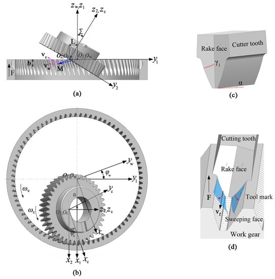
Figure 1.
Skiving coordinate systems and double-rake-face skiving tool. (a) Front view, (b) Top view, (c) Tooth shape, (d) Tooth surface generation.
Three transfer matrices are defined to describe the transformation relations between the coordinate systems: is the transfer matrix from to , is the transfer matrix from to , and is the transfer matrix from to :
where and are the rotation angles of the work gear and the skiving tool, respectively.
The angular velocities of the skiving tool and the work gear are denoted as and , respectively. The relationship between the two angular velocities can be expressed as:
where F = [0 0 F]T is the axial feed velocity of the work gear which represents the axial feed amount of the work gear per revolution, is the helix lead of the work gear, and i is the transmission ratio that can be expressed as:
where and are the numbers of teeth of the skiving tool and the work gear, respectively.
3. Profile Modification by Skiving Based on the Curve-Surface Meshing Principle
The previous study showed that skiving tooth profile errors will be produced if the cutting edges cannot conjugate with the gear tooth flanks [1]. Generally, profile modification of the work gear via skiving is achieved by correcting the tooth profile of the skiving tool in advance according to the profile modification of the work gear. However, due to the indirect and empirical modification method of gear skiving, the cutting edge cannot conjugate with the tooth flank of the work gear. Therefore, the theoretical machining errors of the skived work gear with profile modification are inevitable.
Suppose the cutting edges on the rake face of the skiving tool can be enveloped by the tooth flanks of the work gear with profile modification. In that case, they will be conjugated with the gear tooth flanks, and theoretical skiving errors can be eliminated.
There are two constraints for the curve-surface conjugated cutting-edge point: the point should be located on the rake face of the skiving tool, and the sliding velocity of the point relative to the work gear should be vertical with the gear tooth flank. Therefore, the curve-surface conjugated cutting edge can be expressed in as:
where is the normal vector of a point on the gear tooth flank, is the sliding velocity of the point on the cutting edge relative to the work gear, is the position vector of the point on the rake face of the skiving tool, is the position vector of a point on the gear tooth flank, L is the offset vector of the tool, and a is the center distance vector, as shown in Figure 1. L and a can be expressed as:
The target tooth flank of the work gear is an involute helicoid with profile modification that can be expressed in as follows:
where is the base circle radius of the work gear, u is the involute parameter of the transverse tooth profile, is the rotation angle of the tooth profile about , p is the helix parameter, is the profile modification function taking u as the only variable, and are the components of the unit vector of in and directions that can be expressed in as follows:
Taking profile crowning as a numerical example, the profile modification function can be expressed as:
where represents the radius of profile crowning, is the radius of the midpoint of profile crowning, is the radius of the endpoint of profile crowning, and is the profile crowning, at the position .
Based on the skiving kinematical principles, the sliding velocity of the cutting point relative to the work gear can be divided into two parts: the relative velocity formed by the relative rolling between the skiving tool and the work gear, and differential velocity , coplanar with the gear tooth flank as shown in Figure 1d, formed by the axial differential feed F. Hence, the sliding velocity can be expressed as:
Since the differential velocity and the normal vector of the gear tooth flank are perpendicular, the dot product of the two vectors is zero, i.e., , Equation (3) can be simplified as follows:
If the point can fulfill Equation (10), the meshing point between the cutting edge and the target tooth flank can be obtained [1]. The normal vector and the sliding velocity should be transferred to the same coordinate system to conveniently solve the meshing equation:
where is the upper-left 3 × 3 submatrix of and is the upper-left 3 × 3 submatrix of . Equation (11) contains the transformation calculations of coordinates and vectors, so the dimensions of the transformation results are different, but when they are combined, the dimensions should be unified as a four-dimensional vector.
The curve-surface conjugated cutting edge of the skiving tool can be obtained by transferring the meshing point form to . Since the cutting edges are conjugated with the tooth flanks of the work gear, the theoretical profile error of the skived work gear with profile modification can be eliminated.
4. Lead Modification by Skiving with Changeable Shaft Angle during Cutting
Generally, lead modification of gear skiving is achieved based on the conventional shaping, hobbing, or grinding by varying the center distance between the cutter and work gear successively in the cutting process. This may result in the twist of gear tooth flank of helical gear that can hardly be eliminated [14,15,16]. Similarly, lead modification of the gear by skiving is achieved by changing the center distance between the tool and the work gear during cutting to obtain the desired inconsistent tooth thickness in the tooth width direction. Since the differential velocity can hardly be perpendicular to the normal vector of the modified gear tooth flank on the pitch cylinder developed surface, as shown in Figure 2b, the gear tooth flank can be easily twisted, especially when the work gear is helical and the helix angle is relatively large [12]. Figure 2b,c are plotted on the unfold plane of pitch cylinder as shown in Figure 2a, and the direction of “B” is parallel to as shown in Figure 1 while the direction of “T” is coincident with the tangent direction of the pitch circle on the point “M”.
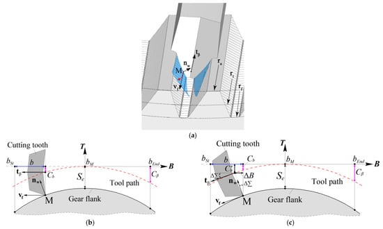
Figure 2.
Skiving methods for lead crowning gear. (a) gear tooth flank enveloped by the cutting tooth, (b) general method of the skiving, (c) method of the skiving with alterable shaft angle.
The alterable shaft angle skiving method is proposed to decrease the tooth flank twist of the work gear with lead modification. The two flanks of the work gear tooth are separately skived with alterable shaft angle in the cutting process. Hence, different lead modification requirements of the two tooth flanks can be achieved, and the tooth flank twist can be decreased more easily.
Taking lead crowning as a numerical example, the lead modification function on the pitch circle can be expressed as:
where b represents the position of lead crowning in the direction, as shown in Figure 1, is the midpoint of the lead modification, is the endpoint of the lead modification, and is the lead modification at the position . The start point of the lead modification is , as shown in Figure 2.
Compared with the general machining method of lead crowning gears by skiving, as shown in Figure 2b, the position and the orientation of the skiving tool on the tool path are adjusted in the alterable shaft angle skiving method to ensure that the helix tangent vector of the cutting tooth is perpendicular to the normal vector of the gear tooth flank as shown in Figure 2c. In this case, the direction of differential velocity can be adjusted to be as perpendicular to the normal vector as possible. Three additional variables are required to describe the adjustments: is the variation of shaft angle between the skiving tool and the work gear which can be obtained by calculating the arctangent of the derivation of , is the additional movement of the skiving cutter in the direction as shown in Figure 1, and is the new lead crowning modification function.
where is the half tooth thickness of the cutting tooth on the pitch circle.
5. Mathematical Model of the Skived Gear Tooth Flank with Modifications
Theoretical study of the skiving cutting edge enveloping the gear tooth flank is carried out to verify the feasibility of the proposed skiving method for gears with profile and lead modification. Based on the calculation model of curve-surface conjugated cutting edges for the gear tooth flanks with profile modification, the position vector and the tangent vector of a point on the cutting edge of the skiving tool (taking u as the unique variable) can be expressed in as follows:
The position vector and the tangent vector of the cutting point on the cutting edge can be expressed in as follows:
where is the upper-left 3 × 3 submatrix of .
The relative sliding velocity of the cutting point on the cutter edge relative to the work gear can be expressed in as follows:
where is the shaft angle at different positions of lead modification that can be expressed as:
The differential velocity of the cutting point on the cutter edge relative to the work gear caused by the axial feed movement can be expressed in as:
The tangent vector of a point on the cutting edge is coplanar with two velocity vectors and at each cutting position. Therefore, the following expression is true:
If the point can satisfy Equation (24), it is a tooth flank point of the work gear after being transformed into the work gear coordinate system . The entire tooth flank of the work gear can be obtained by solving the upper meshing equations at each axial feeding position.
A numerical example of the cutting edge enveloping the gear tooth flank is carried out, which investigates the skiving accuracy of the gears with profile and lead modifications via the proposed methods. The basic parameters of the work gear used in the calculation are listed in Table 1. Basic parameters of skiving cutter and tool setting parameters are listed in Table 2.

Table 1.
Basic parameters of the work gear.
Table 2.
Basic parameters of the skiving cutter and tool setting parameters.
Based on the parameters of tooth profile and lead modification listed in Table 3, profile crowning and lead crowning can be added to the tooth flanks of the work gear by use of Equations (8) and (13). The tooth surface topographic of the work gear is shown in Figure 3a. Figure 3b shows profile deviation curves of the work gear at tooth widths of 10 mm. Figure 3c is the calculated helix deviation of the work gear at a radius of 106.5 mm. The crowning amounts of the crowned work gear surface are listed in Table 4.
Table 3.
Parameters of tooth profile and lead modification.
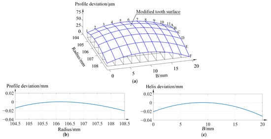
Figure 3.
Crowned work gear surfaces. (a) topography of the crowned work gear surfaces, (b) profile deviation, (c) helix deviation.
Table 4.
Crowning amounts of the crowned work gear surface. (Unit: μm).
Based on the upper theoretical studies of profile modification and lead modification by skiving, the coordinates of the curve-surface conjugated cutting edge and the corresponding tool path can be calculated. The curve-surface conjugated cutting edge of the skiving tool can be obtained by solving the Equation (10) and transferring the meshing point form to . Partial data of the cutting edge are provided in Table 5. The skiving tool path with alterable shaft angle can be calculated by using Equations (13)–(15). Partial data of the tool path are provided in Table 6.
Table 5.
Partial data of coordinates of the side cutting edge.
Table 6.
Partial data of skiving tool path.
Based on the theoretical study of the skiving cutting edge enveloping the gear tooth flank, a comparison between the general skiving method and the alterable shaft angle skiving method for eliminating the tooth flank twist of the work gear with lead crowning is carried out.
The deviation contour plot of the tooth flank enveloped via the general skiving method is shown in Figure 4a. This plot is obtained by comparing the enveloped gear tooth flank and the standard involute helicoid. It can be seen from the figure that the deviation of the side of the tooth surface is negative, which means the material of the tooth flank is removed at this part. Figure 4b shows profile deviation curves of the work gear at tooth widths of 0 mm, 10 mm, and 20 mm. Figure 4c is the calculated helix deviation of the work gear at a radius of 106.5 mm. According to the contour plot and the profile deviation plot, the shape and amplitude of the tooth profile deviation curves at different tooth widths are inconsistent. Moreover, the midpoint of tooth profile modification at a tooth width of 20 mm shifts to the addendum compared with the tooth profile at 0 mm, while the midpoint of modification at the tooth width of 0 mm shifts to dedendum, which means that a tooth flank twist appears.
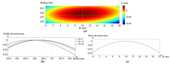
Figure 4.
Calculated deviations of the gear tooth flank enveloped via general skiving method. (a) deviation contour plot, (b) profile deviation, (c) helix deviation.
The deviation contour plot of the tooth flank enveloped via the alterable shaft angle skiving method is shown in Figure 5b. The shapes and amplitudes of the tooth profile curves are quite similar, which means the tooth flank twist is decreased.
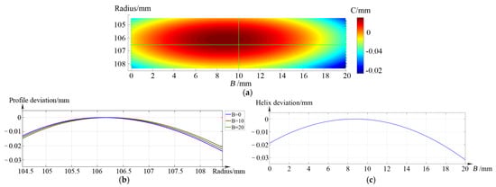
Figure 5.
Calculated deviations of the gear tooth flank enveloped via alterable shaft angle skiving method. (a) deviation contour plot, (b) profile deviation, (c) helix deviation.
6. Skiving Simulation and Verification
Presently, the proposed skiving method with alterable shaft angle cannot be realized on the existing gear skiving machine tools, because the swing axis A must be fixed in the skiving process, which is used to set the shaft angle , so machining simulation analyses are carried out using UG software which offers better performance in surface modeling. Based on the method shown in [17], the feasibility of the proposed skiving method for gears with profile and lead modifications can be verified. The five-axis skiving machine tool model is built as shown in Figure 6. The center distance a can be set by moving the X axis. The offset distance can be set by moving the Y axis. The feeding of the work gear can be driven by the Z axis. The A axis is the swing axis that rotates about the X-axis, which can be used to set the shaft angle . The and the axes are the work gear rotation axis and the skiving tool rotation axis, respectively, which are coupled together by the electronic gearbox.
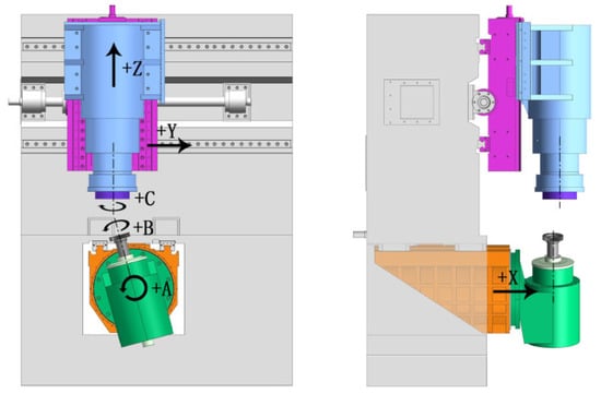
Figure 6.
Model of the skiving machine tool.
The basic parameters of the skiving cutter and the work gear are shown in Table 1 and Table 2. The curve-surface conjugated cutting edge and the skiving cutter’s tool path can be obtained using the proposed mathematical models in Section 3 and Section 4. In the gear skiving simulation, the feed amount of the work gear is 0.4 mm per revolution. Therefore, the teeth flanks of the work gear are composed of a series of tool marks left by the cutting edges of the skiving tool. Tooth flank deviation of the skived gear should be obtained to verify the abovementioned mathematical models. Thus, a comparison between the skived gear tooth flank and the standard involute helicoids is conducted, and the coordinates of points on the transverse tooth profiles and the lead curves of the enveloped tooth flanks are measured in the UG software. Profile and lead deviations can be calculated using the algorithms from [11]. The tooth profile deviation can be obtained by comparing the measured transverse tooth profile of the work gear tooth flank with the standard involute tooth profile. The lead deviation can be obtained by comparing the measured helical line on the pitch cylinder of the work gear tooth with the theoretical helix.
Two comparative simulations are carried out. The gear tooth is generated in simulation I via the general skiving method. The deviation contour plot of the enveloped gear tooth flank and the measurement results of the tooth profile deviations and the lead deviation are shown in Figure 7a. Figure 7b shows profile deviation curves of the work gear at tooth widths of 0 mm, 10 mm, and 20 mm. Figure 7c is the measured helix deviation of the work gear at a radius of 106.5 mm. It can be seen from the figures that the measurement results of tooth flank deviation are extraordinarily close to the theoretical calculations. The shape of the gear tooth profile changes from the left side of the gear tooth to the right side, while the maximum variation of the profile deviation in the tooth width direction is approximately 20 μm, which means that a tooth flank twist appears. Since the total profile modification amount is only 15 μm, the twist of the tooth flank is serious and nonignorable.
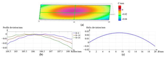
Figure 7.
Measured deviations of the tooth flank enveloped via general skiving method. (a) deviation contour plot, (b) profile deviation, (c) helix deviation.
Simulation II is conducted based on the proposed alterable shaft angle skiving method for gears with modifications proposed in this paper. The enveloped gear tooth flanks and the measurement results are shown in Figure 8. The maximum variation of the profile deviation in the tooth width direction is decreased to approximately 3 μm. Therefore, it can be concluded that the tooth flank twist can be decreased and skiving accuracy can be improved using the proposed skiving method for gears with profile and lead modification.
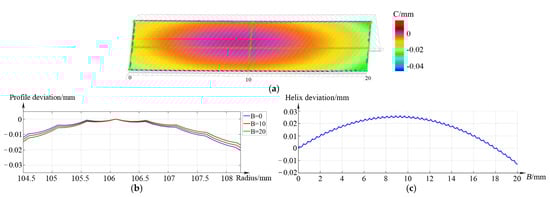
Figure 8.
Measured deviations of the tooth flank enveloped via alterable shaft angle skiving method. (a) deviation contour plot, (b) profile deviation, (c) helix deviation.
7. Conclusions
In this paper, a new type of skiving tool with double rake faces for each cutting tooth was proposed. The two side rake angles and the cutting edges of the cutting tooth can be separately designed to more easily meet different modification requirements of the two flanks of the work gear teeth.
The algorithm of the curve-surface conjugated cutting edge of the skiving tool for enveloping the tooth flanks of the work gear with profile modification was proposed. The theoretical skiving error of the work gears with profile modification can be eliminated.
The algorithm of the skiving tool path with an alterable shaft angle was proposed. It was observed that the tooth flank twist of the skived work gear with lead crowning modification could be decreased.
The skiving simulations were carried out. The results show that the tooth profile accuracy of the skived work gear with profile modification can be ensured, and the twist of gear tooth flanks can be decreased using the proposed skiving method.
Author Contributions
Z.G.: General concept, original draft preparation, writing and editing. R.X.: Introduction, review, and editing. W.G.: Simulations. W.H.: Further simulation of skiving, measuring. F.G.: Calculation of tooth profile deviation. Y.Z.: Preparation of conclusions and editing. All authors have read and agreed to the published version of the manuscript.
Funding
The authors gratefully acknowledge this project funded by China Postdoctoral Science Foundation (CPSF No. 2020M673602XB), Natural Science Foundation of Shaanxi Province (NSFSP No. 2022JM-235), Collaborative Innovation Center of Modern Equipment Green Manufacturing in Shaanxi Province (Grant No. 102-451421002), and Natural Science Project of Shaanxi Provincial Department of Education (20JK0790).
Data Availability Statement
Not applicable.
Conflicts of Interest
The authors declare no conflict of interest.
Nomenclature
| the fixed coordinate system of work gear | |
| the fixed coordinate system of tool | |
| shaft angle | |
| center distance | |
| offset distance | |
| the attached coordinate system of work gear | |
| the attached coordinate system of tool | |
| transfer-matrix from to | |
| transfer-matrix from to | |
| transfer-matrix from to | |
| rotation angle of work gear | |
| rotation angle of honing wheel | |
| angular velocity of work gear | |
| angular velocity of honing wheel | |
| F | axial feed velocity of work gear |
| helix lead of work gear | |
| i | transmission ratio |
| number of teeth of tool | |
| number of teeth of work gear | |
| normal vector of a point on gear tooth flank | |
| sliding velocity of cutting point | |
| position vector of a point on rake face | |
| position vector of a point on gear tooth flank | |
| L | offset vector of tool |
| a | center distance vector |
| base circle radius of work gear | |
| u | involute parameter of transverse tooth profile |
| rotation angle of transverse tooth profile | |
| profile modification function | |
| radius of profile modification | |
| radius of the midpoint of profile modification | |
| radius of the endpoint of profile modification | |
| profile modification at the position | |
| unit vector component of in direction | |
| unit vector component of in direction | |
| relative velocity | |
| differential velocity | |
| upper-left 3 × 3 submatrix of | |
| upper-left 3 × 3 submatrix of | |
| lead-crowning modification function | |
| b | position variable of lead modification |
| midpoint of lead modification | |
| endpoint of lead modification | |
| lead modification amount at position | |
| variation of shaft angle | |
| additional movement of skiving cutter | |
| new lead-crowning modification function | |
| half tooth thickness of cutting tooth | |
| tangent vector of a point on cutting edge | |
| upper-left 3 × 3 submatrix of | |
| new shaft angle |
References
- Guo, Z.; Mao, S.M.; Li, X.E.; Ren, Z.Y. Research on the theoretical tooth profile errors of gears machined by skiving. Mech. Mach. Theory 2016, 97, 1–11. [Google Scholar] [CrossRef]
- Wang, P.; Liu, F.C.; Li, J. Analysis and optimization of gear skiving parameters regarding interference and theoretical machining deviation based on chaos map. Int. J. Adv. Manuf. Technol. 2021, 112, 2161–2175. [Google Scholar] [CrossRef]
- Bruno, V.; Volker, S. Three-dimensional modeling of gear skiving kinematics for comprehensive process design in practical applications. CIRP Ann. 2021, 70, 99–102. [Google Scholar]
- Lin, X.H.; Liu, Y.H.; Sun, S.L.; Jin, G.; Hong, R.J. Prediction and optimization of gear skiving parameters and geometric deviations. Int. J. Adv. Manuf. Technol. 2022, 121, 4169–4185. [Google Scholar] [CrossRef]
- Tomokazu, T.; Morimasa, N.; Daisuke, I. Gear skiving for mass production. In Proceedings of the JSME International Conference on Motion and Power Transmissions, Kyoto, Japan, 28 February 2017. [Google Scholar]
- Ren, Z.W.; Fang, Z.L.; Kizaki, T.; Feng, Y.N.; Nagata, T.; Komatsu, Y.; Sugita, N. Understanding local cutting features affecting surface integrity of gear flank in gear skiving. Int. J. Mach. Tools Manuf. 2022, 172, 103818. [Google Scholar] [CrossRef]
- Kojima, M.; Nishijima, K. Gear skiving of involute internal spur gear: (part 1. on the tooth profile). Bull. JSME 2008, 17, 511–518. [Google Scholar] [CrossRef]
- Tomokazu, T.; Nobuaki, K.; Morimasa, N.; Daisuke, I.; Ichiro, M. Calculation model for internal gear skiving with a pinion-type cutter having pitch deviation and a run-out. In Proceedings of the ASME 2015 International Design Engineering Technical Conferences & Computers and Information in Engineering Conference, Boston, MA, USA, 2 August 2015. [Google Scholar]
- Tsai, C.Y.; Lin, P.D. Gear manufacturing using power-skiving method on six-axis CNC turn-mill machining center. Int. J. Adv. Manuf. Technol. 2018, 95, 609–623. [Google Scholar] [CrossRef]
- Tsai, C.Y. Mathematical model for design and analysis of power skiving tool for involute gear cutting. Mech. Mach. Theory 2016, 101, 195–208. [Google Scholar] [CrossRef]
- Guo, Z.; Mao, S.M.; Du, X.F.; Ren, Z.Y. Influences of tool setting errors on gear skiving accuracy. Int. J. Adv. Manuf. Technol. 2017, 91, 3135–3143. [Google Scholar] [CrossRef]
- Guo, E.; Hong, R.; Huang, X.; Fang, C. A correction method for power skiving of cylindrical gears lead modification. J. Mech. Sci. Technol. 2015, 29, 4379–4386. [Google Scholar] [CrossRef]
- Zheng, F.; Zhang, M.; Zhang, W.; Guo, X. Research on the tooth modification in gear skiving. J. Mech. Des. 2019, 140, 084502. [Google Scholar] [CrossRef]
- Huang, C.L.; Fong, Z.H.; Fong, Z.H.; Chen, S.D.; Chang, K.R. Profile correction of a helical gear shaping cutter using the lengthwise-reciprocating grinding method. Mech. Mach. Theory 2009, 44, 401–411. [Google Scholar] [CrossRef]
- Tran, V.T.; Hsu, R.H.; Hsu, R.H.; Tsay, C.B.; Tsay, C.B. Tooth Contact Analysis for a Double-Crowned Involute Helical Gear with Twist-Free Tooth Flanks Generated by Dual-Lead Hob Cutters. J. Mech. Des. 2015, 137, 041001. [Google Scholar] [CrossRef]
- Shih, Y.P.; Chen, S.D. Free-Form Flank Correction in Helical Gear Grinding Using a Five-Axis Computer Numerical Control Gear Profile Grinding Machine. J. Manuf. Sci. Eng. 2012, 134, 041006. [Google Scholar] [CrossRef]
- Nikolaos, T. Calculation of non-deformed chip and gear geometry in power skiving using a CAD-based simulation. Int. J. Adv. Manuf. Technol. 2019, 100, 1779–1785. [Google Scholar]
Disclaimer/Publisher’s Note: The statements, opinions and data contained in all publications are solely those of the individual author(s) and contributor(s) and not of MDPI and/or the editor(s). MDPI and/or the editor(s) disclaim responsibility for any injury to people or property resulting from any ideas, methods, instructions or products referred to in the content. |
© 2023 by the authors. Licensee MDPI, Basel, Switzerland. This article is an open access article distributed under the terms and conditions of the Creative Commons Attribution (CC BY) license (https://creativecommons.org/licenses/by/4.0/).