
Irreversible Demagnetization Improvement Process of Hybrid Traction Motors with Dy-Free Magnets


Abstract
:1. Introduction
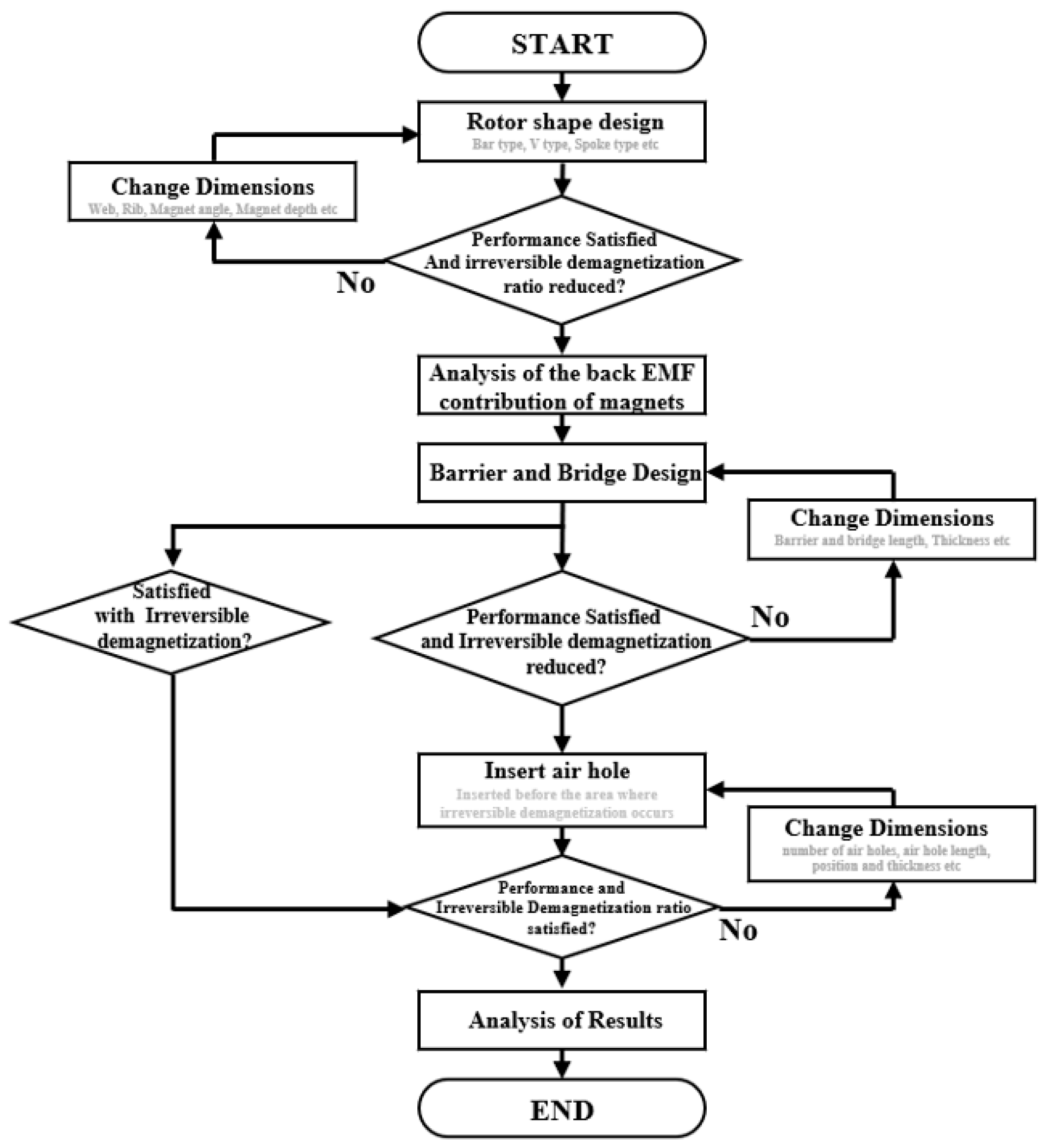
2. Rotor Irreversible Demagnetization Minimizing Design
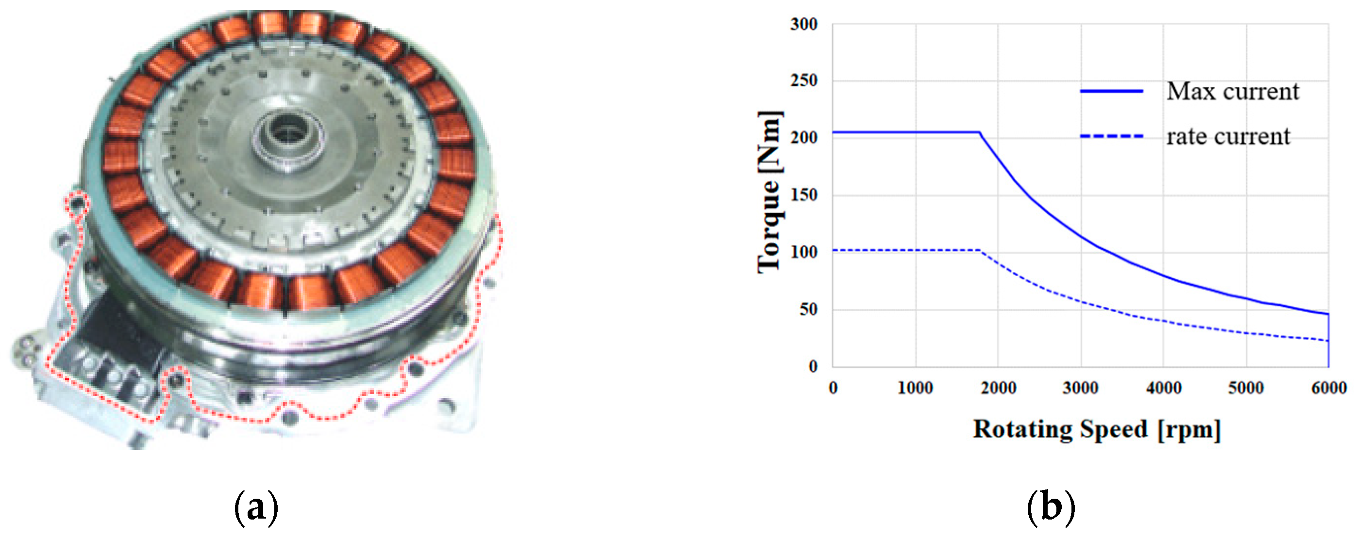
2.1. 35 kW Hybrid Traction Motor Analysis
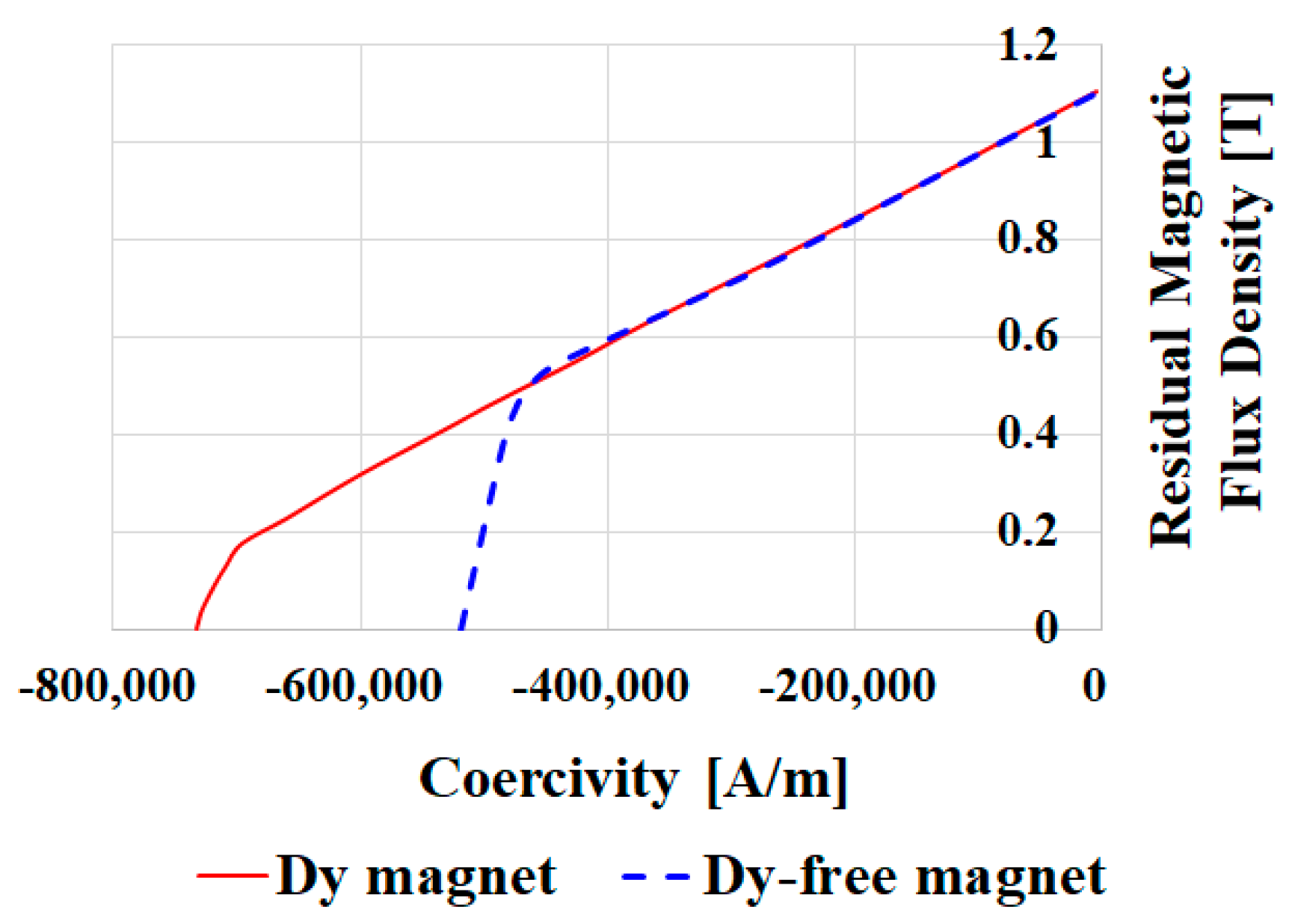
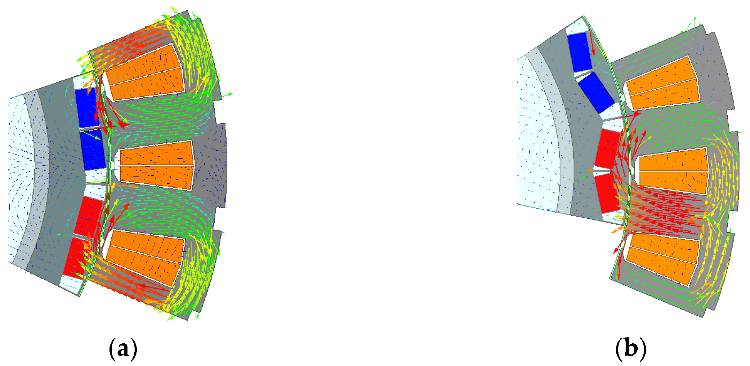
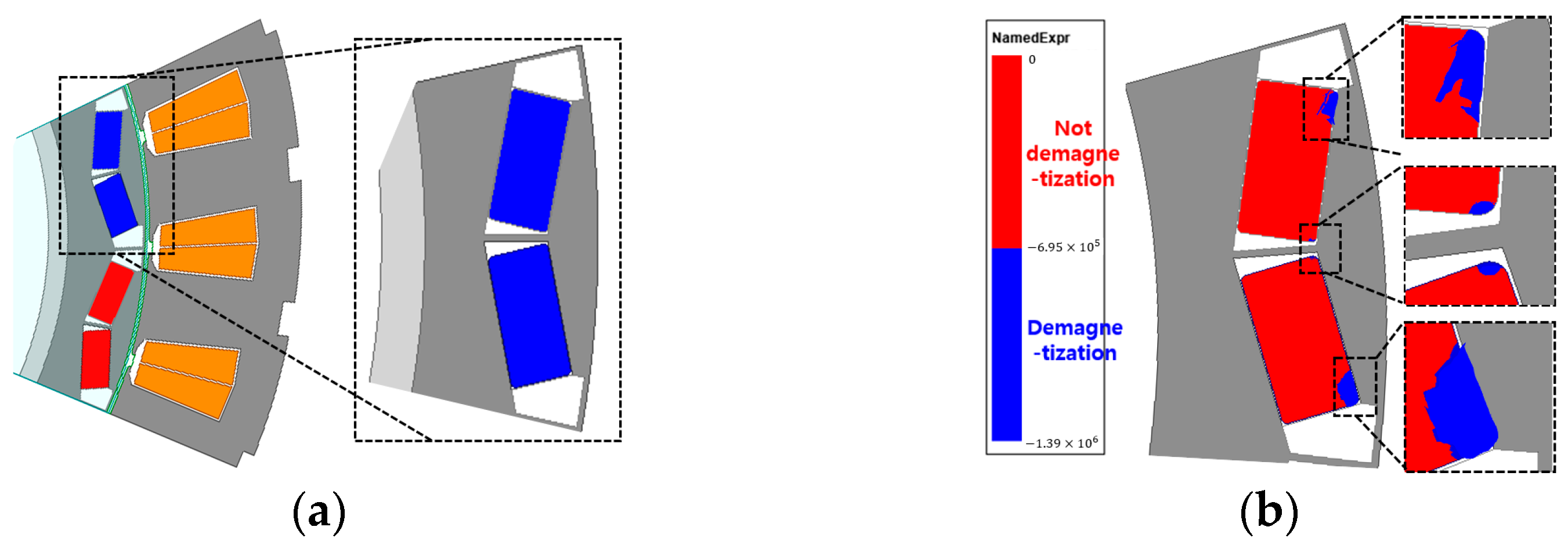
2.2. Rotor Design Resistant to Irreversible Demagnetization
3. Analysis of the Contribution of Permanent Magnets to No-Load Back EMF Generation
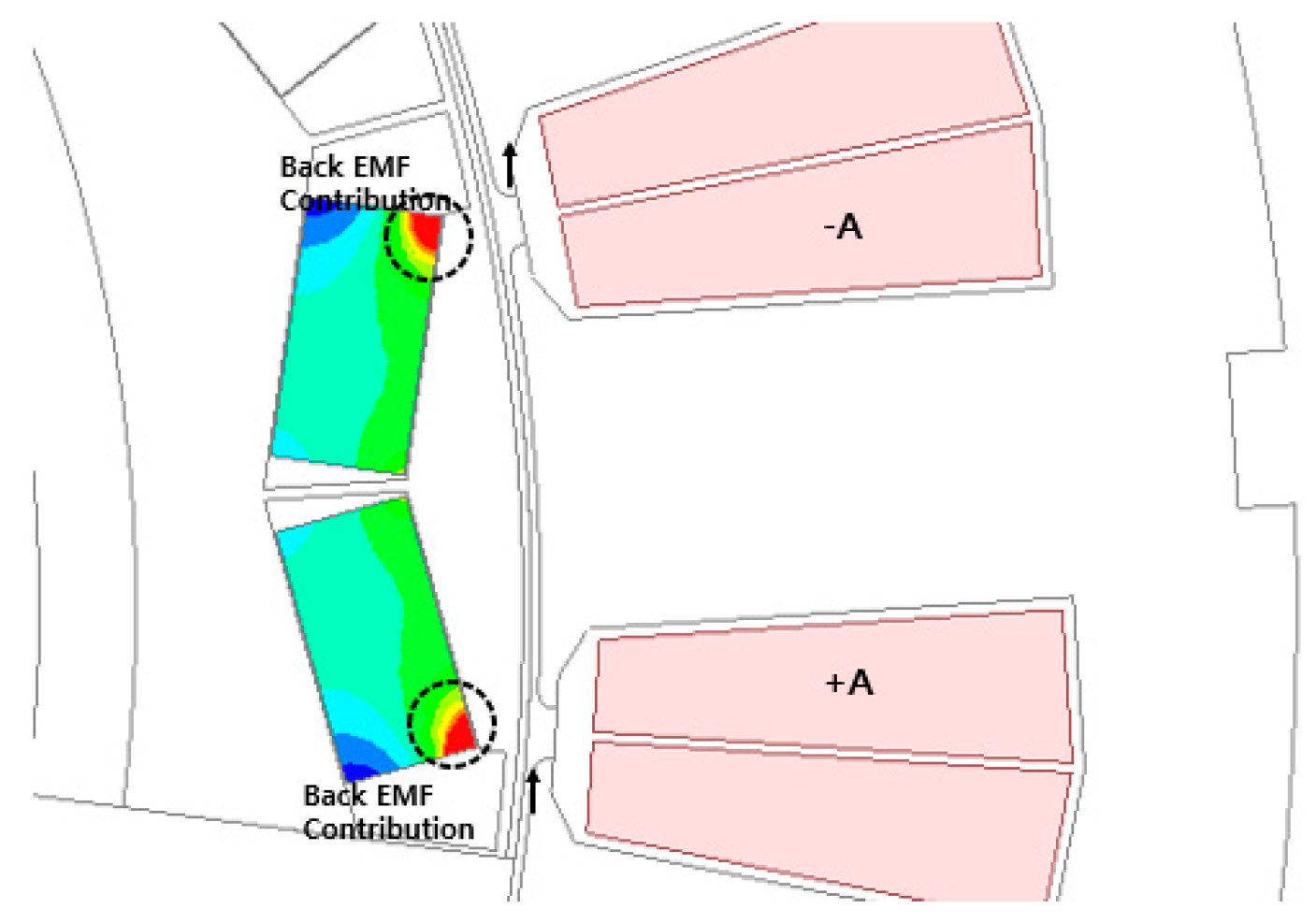
Analysis of Back EMF Contribution Depending on the Magnet Part
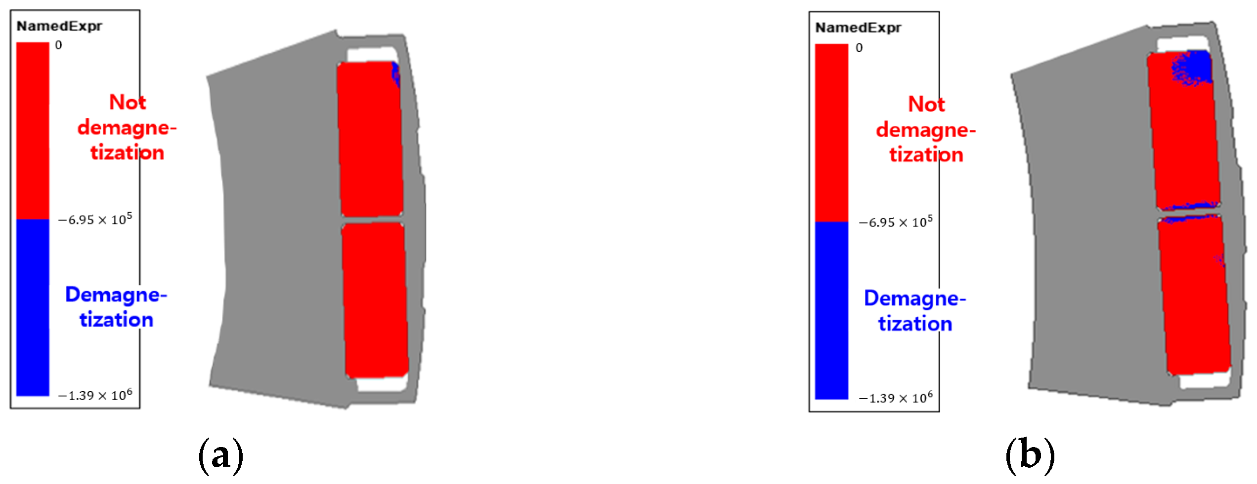
4. Design for Minimizing Irreversible Demagnetization by Analyzing the Back Emf Contribution
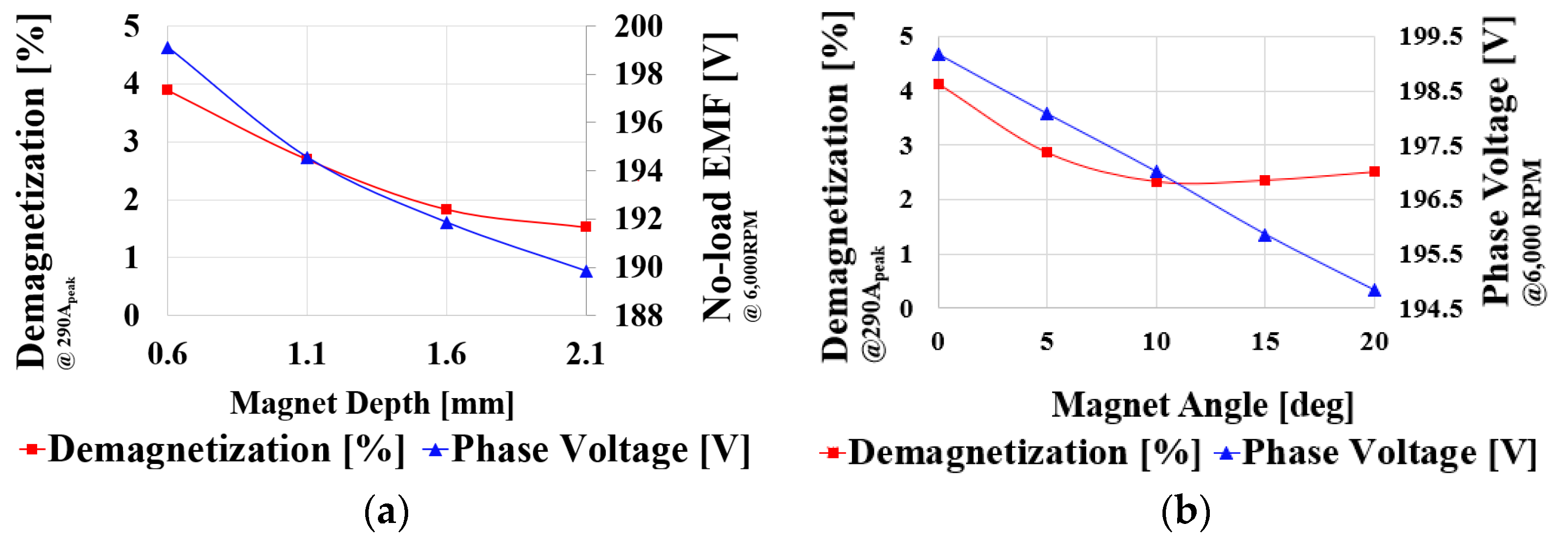
4.1. Design of the Inner Shape of Magnet for Securing Irreversible Demagnetization Magnetic Flux Passage
4.2. Design of the Outer Shape of Magnet for Securing Irreversible Demagnetization Magnetic Flux Passage
4.3. Air Hole Shape Design
5. Characteristic Comparison through Simulation
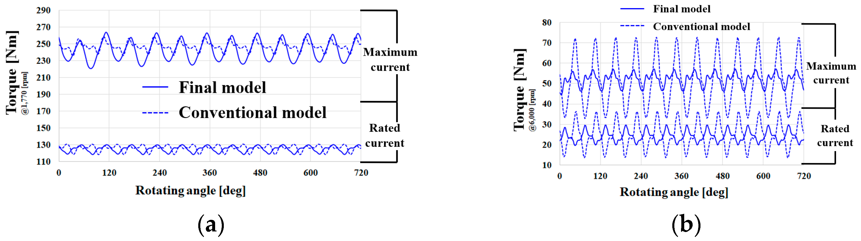
5.1. Electromagnetic Performance Analysis
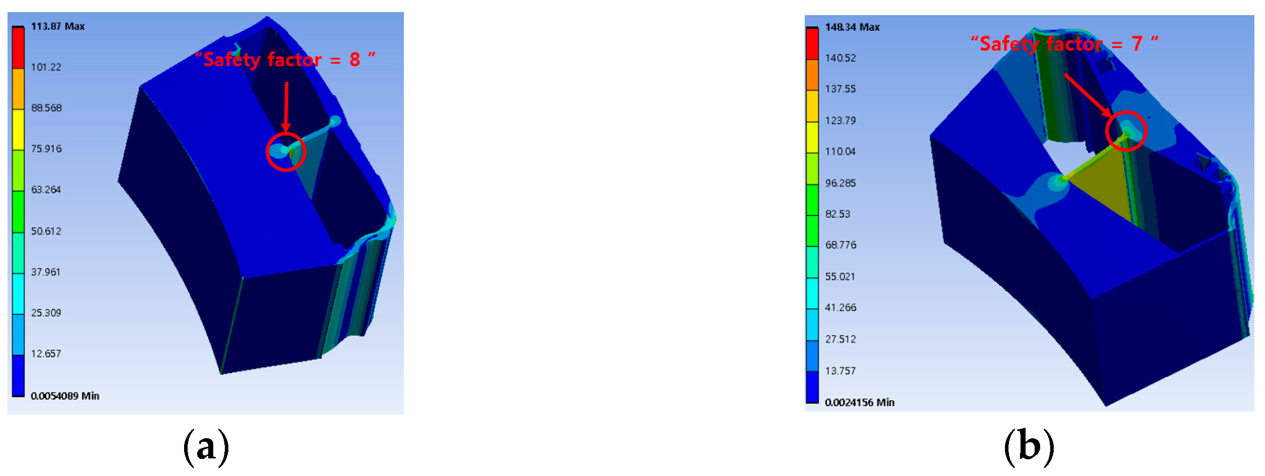
5.2. Comparison of the Mechanical Rigidity
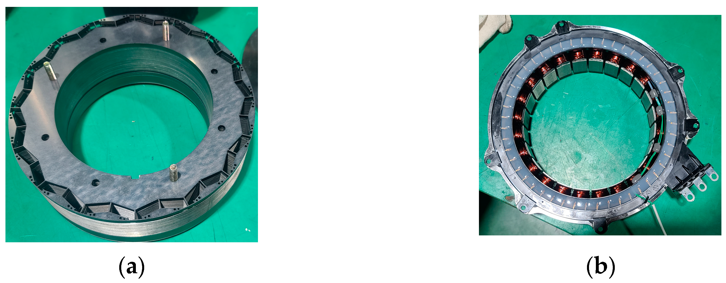
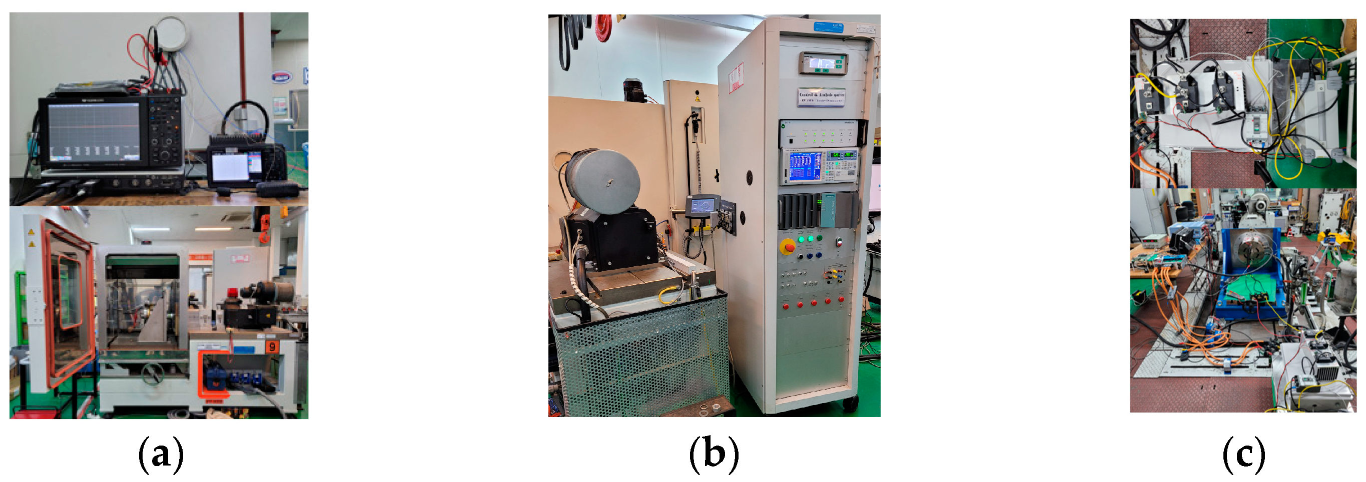
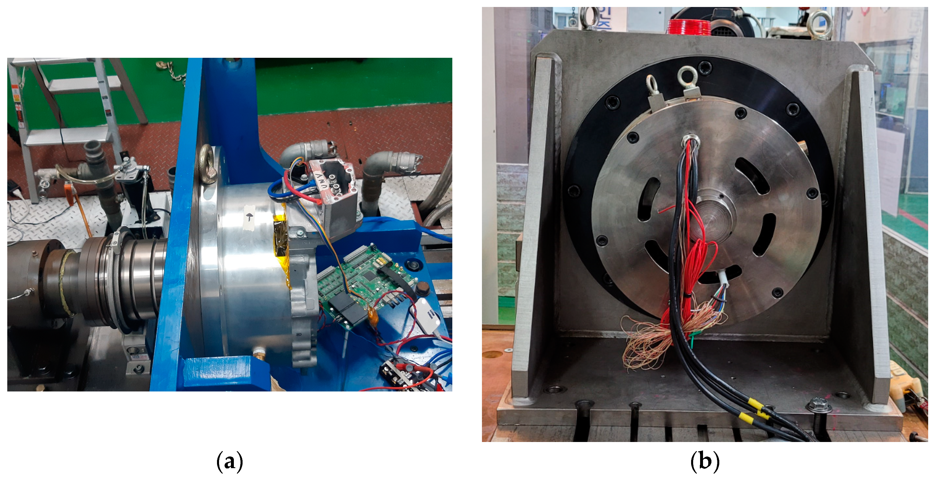
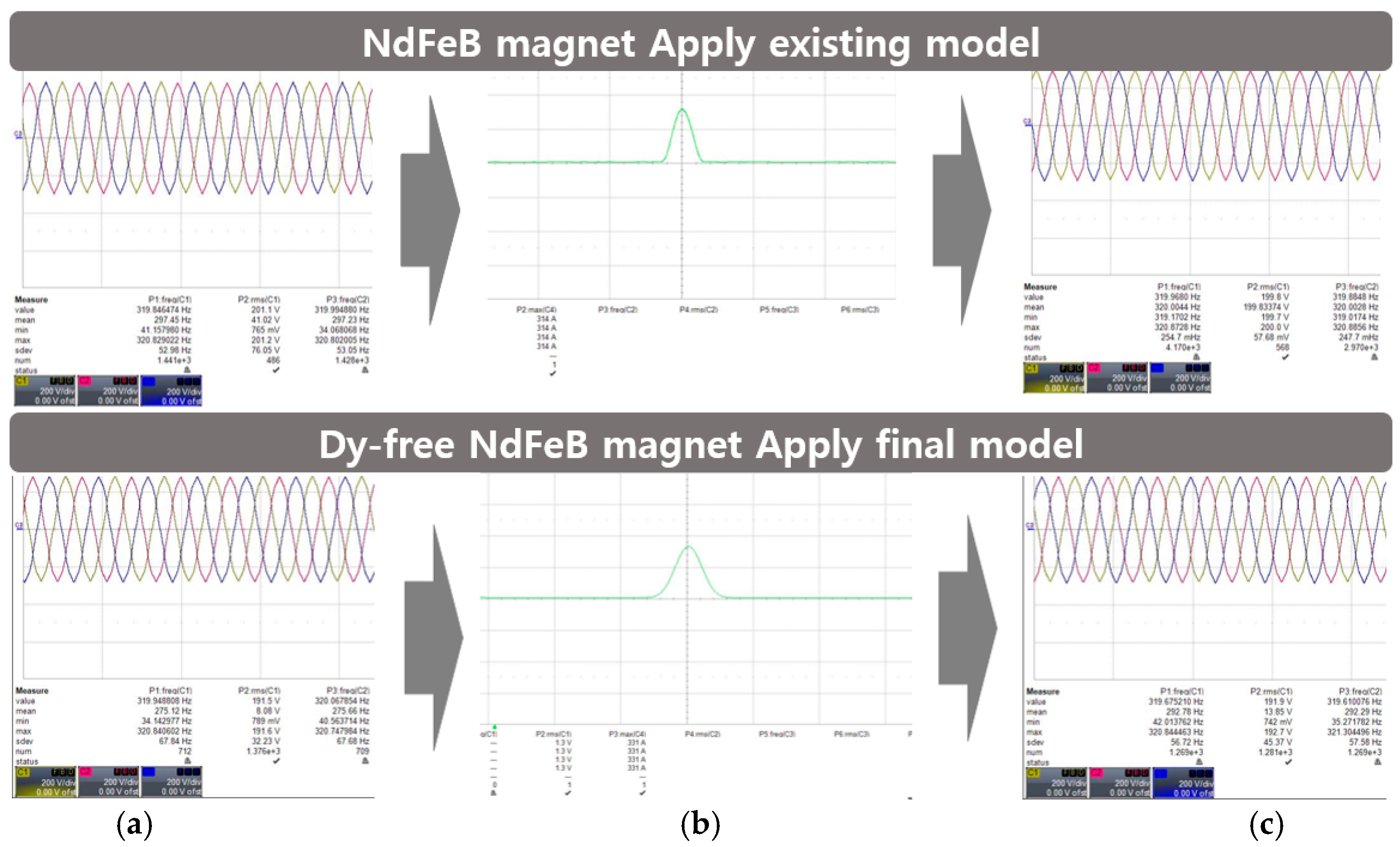
6. Experiments and Results
7. Conclusions
Author Contributions
Funding
Data Availability Statement
Conflicts of Interest
References
- Kim, T.; Lee, H.-W.; Kwak, S. The Internal Fault Analysis of Brushless DC Motors Based on the Winding Function Theory. IEEE Trans. Magn. 2009, 45, 2090–2096. [Google Scholar] [CrossRef]
- Feng, D.Y.; Liu, Z.W.; Zheng, Z.G.; Zhong, X.C.; Zhang, G.Q. Hard Magnetic Properties and Thermal Stability for TbCu7-Type SmCo6.4Si0.3Zr0.3 Alloys with Sm Substituted by Various Rare-Earth Elements. IEEE Trans. Magn. 2015, 51, 2100604. [Google Scholar] [CrossRef]
- Taskaev, S.V.; Skokov, K.P.; Khovaylo, V.V.; Gorshenkov, M.V.; Vasiliev, A.N.; Volkova, O.S.; Bataev, D.S.; Pellenen, A.P.; Gutfleisch, O. Magnetic Properties of Nd and Sm Rare-Earth Metals After Severe Plastic Deformation. IEEE Magn. Lett. 2016, 7, 5203104. [Google Scholar] [CrossRef]
- Saito, F.; Miura, D.; Sakuma, A. Theoretical Study of Gilbert Damping in Rare-Earth Permanent Magnets. IEEE Trans. Magn. 2019, 55, 2101604. [Google Scholar] [CrossRef]
- Poudel, B.; Amiri, E.; Rastgoufard, P.; Mirafzal, B. Toward Less Rare-Earth Permanent Magnet in Electric Machines: A Review. IEEE Trans. Magn. 2021, 57, 900119. [Google Scholar] [CrossRef]
- Chen, L.; Cao, X.; Guo, S.; Di, J.; Ding, G.; Yan, C.; Chen, R.; Yan, A. Coercivity Enhancement of Dy-Free Sintered Nd–Fe–B Magnets by Grain Refinement and Induction Heat Treatment. IEEE Trans. Magn. 2015, 51, 1–3. [Google Scholar] [CrossRef]
- Komlev, A.S.; Gimaev, R.R.; Davydov, A.S.; Zverev, V.I. The influence of chemical impurities on the properties of heavy rare-earth metals (Tb, Dy, Ho): Experimental and theoretical approaches. Materialia 2021, 18, 101166. [Google Scholar] [CrossRef]
- Gimaev, R.R.; Komlev, A.S.; Davydov, A.S.; Kovalev, B.B.; Zverev, V.I. Magnetic and Electronic Properties of Heavy Lanthanides (Gd, Tb, Dy, Er, Ho, Tm). Crystals 2021, 11, 82. [Google Scholar] [CrossRef]
- Kim, B.-C.; Lee, J.-H.; Kang, D.-W. A Study on the Effect of Eddy Current Loss and Demagnetization Characteristics of Magnet Division. IEEE Trans. Appl. Supercond. 2020, 30, 600805. [Google Scholar] [CrossRef]
- Lin, D.; Zhou, P.; Bracken, E. Generalized Algorithm to Deal with Temperature-Dependent Demagnetization Curves of Permanent Magnets for FEA. IEEE Trans. Magn. 2021, 57, 7402706. [Google Scholar] [CrossRef]
- Jeong, G.; Kim, H.; Lee, J. A Study on the Design of IPMSM for Reliability of Demagnetization Characteristics-Based Rotor. IEEE Trans. Appl. Supercond. 2020, 30, 5204805. [Google Scholar] [CrossRef]
- Yoon, K.-Y.; Hwang, K.-Y. Optimal Design of Spoke-Type IPM Motor Allowing Irreversible Demagnetization to Minimize PM Weight. IEEE Access 2021, 9, 65721–65729. [Google Scholar] [CrossRef]
- Wang, W.; Zheng, P.; Wang, M.; Liu, Y.; Fu, Z.; Sui, Y. Demagnetization and Permanent-Magnet Minimization Analyses of Less-Rare-Earth Interior Permanent-Magnet Synchronous Machines Used for Electric Vehicles. IEEE Trans. Magn. 2018, 54, 8109505. [Google Scholar] [CrossRef]
- Lee, K.; Kim, W.; Jin, C.; Lee, J. Local demagnetisation analysis of a permanent magnet motor. IET Electr. Power Appl. 2015, 9, 280–286. [Google Scholar] [CrossRef]
- Hou, Z.; Huang, J.; Liu, H.; Liu, Z.; Ye, M.; Yang, J. No-load losses based method to detect demagnetisation fault in permanent magnet synchronous motors with parallel branches. IET Electr. Power Appl. 2017, 11, 471–477. [Google Scholar] [CrossRef]
- Nishiyama, N.; Uemura, H.; Honda, Y. Highly Demagnetization Performance IPMSM Under Hot Environ-ments. Ieee Trans. Ind. Appl. 2019, 55, 265–272. [Google Scholar] [CrossRef]
- Jeong, C.L.; Hur, J. Optimization Design of PMSM With Hybrid-Type Permanent Magnet Considering Irreversible Demagnetization. Ieee Trans. Magn. 2017, 53, 8110904. [Google Scholar] [CrossRef]


| Description | Value | Unit |
|---|---|---|
| Pole/Slot Phase | 16/24/3 | - |
| Power | 35 | kW |
| Maximum current/Rated current | 205/102.5 | Arms |
| Maximum speed/Rated speed | 6000/1770 | rpm |
| Maximum torque/Rated torque | 205/102.5 | Nm |
| Stator diameter | 280 | mm |
| Rotor diameter | 200 | mm |
| Turns/Number of parallel | 69/8 | - |
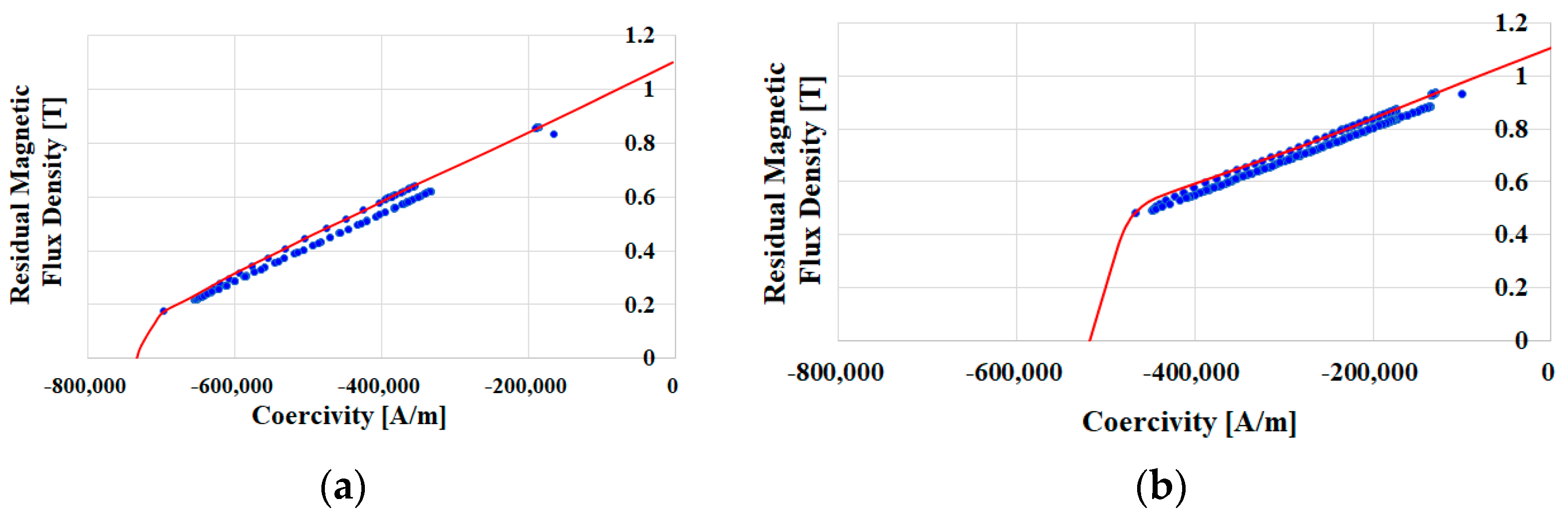
| Magnet material | N42UH | - |
| Coercive force (At 150 °C) | −760 | kA/m |
| Conventional Model | Dy-Free Magnet Insertion into Conventional Model | Final Model | |
|---|---|---|---|
| (Maximum Current/ Rated Current) | (Maximum Current/ Rated Current) | (Maximum Current/ Rated Current) | |
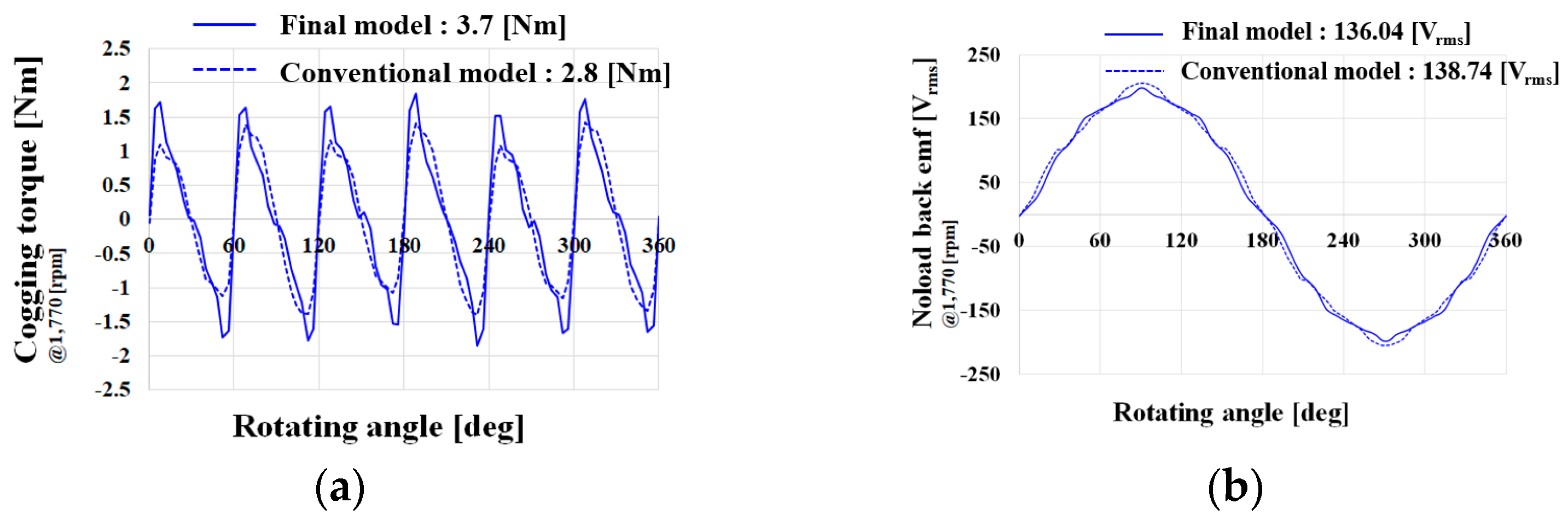
| No-load back EMF (@1770 rpm) | 138.74 [Vrms] | 138.03 [Vrms] | 136.04 [Vrms] |
| Cogging torque | 3.7 [Nm] | 2.85 [Nm] | 2.8 [Nm] |
| Rated speed at torque ripple | 9.87/9.25 [Nm] | 13.05/23.86 [Nm] | 9.31/18 [Nm] |
| Maximum speed at torque ripple | 77.52/93.02 [Nm] | 24.38/51.06 [Nm] | 24.48/42.38 [Nm] |
| Rated speed at torque | 126.09/247.01 [Nm] | 125.58/245.91 [Nm] | 124.78/242.15 [Nm] |
| Maximum speed at torque | 24.49/51.03 [Nm] | 24.38/51.06 [Nm] | 24.13/51.29 [Nm] |
| Irreversible demagnetization | 0.37 [%] | 24.14 [%] | 0.55 [%] |
| Before Applying Anti-Magnetic Field | After Applying Anti-Magnetic Field | Demagnetization Ratio | |
|---|---|---|---|
| Conventional model with a NdFeB magnet | 193.74 [Vrms] | 193.02 [Vrms] | 0.37 [%] |
| Final model with a Dy-free NdFeB magnet | 201.47 [Vrms] | 200.36 [Vrms] | 0.55 [%] |
| Before Applying Diamagnetic Field | After Applying Diamagnetic Field | Diamagnetic Field Applied Current | Demagnetization Ratio | ||
|---|---|---|---|---|---|
| FEM simulation results | Conventional model | 193.74 [Vrms] | 193.02 [Vrms] | 347 [Apeak] | 0.37 [%] |
| Final model | 201.47 [Vrms] | 200.36 [Vrms] | 347 [Apeak] | 0.55 [%] | |
| production experiment results | Conventional model | 192.1 [Vrms] | 191.7 [Vrms] | 314 [Apeak] | 0.21 [%] |
| Final model | 199.9 [Vrms] | 199.1 [Vrms] | 331 [Apeak] | 0.4 [%] | |
Disclaimer/Publisher’s Note: The statements, opinions and data contained in all publications are solely those of the individual author(s) and contributor(s) and not of MDPI and/or the editor(s). MDPI and/or the editor(s) disclaim responsibility for any injury to people or property resulting from any ideas, methods, instructions or products referred to in the content. |
© 2022 by the authors. Licensee MDPI, Basel, Switzerland. This article is an open access article distributed under the terms and conditions of the Creative Commons Attribution (CC BY) license (https://creativecommons.org/licenses/by/4.0/).
Share and Cite
Song, S.-W.; Pyo, H.-J.; Nam, D.-W.; Lee, J.; Kim, W.-H. Irreversible Demagnetization Improvement Process of Hybrid Traction Motors with Dy-Free Magnets. Machines 2023, 11, 4. https://doi.org/10.3390/machines11010004
Song S-W, Pyo H-J, Nam D-W, Lee J, Kim W-H. Irreversible Demagnetization Improvement Process of Hybrid Traction Motors with Dy-Free Magnets. Machines. 2023; 11(1):4. https://doi.org/10.3390/machines11010004
Chicago/Turabian StyleSong, Si-Woo, Hyun-Jo Pyo, Dong-Woo Nam, Ju Lee, and Won-Ho Kim. 2023. "Irreversible Demagnetization Improvement Process of Hybrid Traction Motors with Dy-Free Magnets" Machines 11, no. 1: 4. https://doi.org/10.3390/machines11010004
APA StyleSong, S.-W., Pyo, H.-J., Nam, D.-W., Lee, J., & Kim, W.-H. (2023). Irreversible Demagnetization Improvement Process of Hybrid Traction Motors with Dy-Free Magnets. Machines, 11(1), 4. https://doi.org/10.3390/machines11010004