Abstract
In the study of coal mining, the position and posture, the working status, and the straightness of the hydraulic support are critical to the safety of the coal mine. To detect and control the position of a hydraulic support, a model for solving the self-position and posture and a model for solving the relative position and pose of a hydraulic support based on the principle of three points determining a plane in space were established. Then, with the help of particle swarm optimization algorithm and Bang-Bang control algorithm, the hydraulic support position and the posture detection and control system are constructed. Finally, according to the requirements of sensor data collection and online monitoring of the position and posture of hydraulic support, a hydraulic support posture detection and control system is developed, and the simulation experiments of hydraulic support cylinder movement sample collecting, hydraulic support following motion and hydraulic support independent following machine are carried out on the self-developed three-machine intelligent control simulation experiment platform of the working face. However, the test under this simulation platform did not add the load of the top beam. The results show that the self-pose solution model and the relative-pose solution model of the hydraulic support can be used to quickly monitor the position and posture of the hydraulic support group. In the hydraulic support cylinder following motion movement, the largest following error of each cylinder is the balance cylinder, and its maximum error is 2.6 mm. In the hydraulic support independent following machine simulation, the maximum motion error of the support base is 2.2 mm. The position and posture detection and control system developed for hydraulic support can realize accurate detecting and control the position and posture of hydraulic support, as well as meet the requirements for industrial applications.
1. Introduction
Coal is the main energy source in China, and the development of China’s economy cannot be separated from the support of the coal industry. In addition, the digitization and intellectualization of coal mines are the hot spots of coal mining technology research. Fully mechanized coal mining equipment mainly includes hydraulic support, shearer and scraper conveyor. As the key support equipment of the working equipment, the hydraulic support is very critical, which is the strength and support stability that determines the coal mining efficiency. At present, the length of mechanized coal mining equipment is generally 120–300 m [1]. Under ideal circumstances, the hydraulic support is distributed in a straight line in the working equipment. However, due to the influence of the underground working environment, such as the sliding and pulling frame, the support will appear in a tilt, twist, pitch, dislocation and other non-ideal positions, and the straightness of the support group is not up to standard. It is not conducive to the coordinated support of the roof and the coordinated operation of the working equipment, so it is necessary to accurately monitor and control the pose of the hydraulic support.
Young and Kristian Sandstorm et al. respectively realized the remote monitoring of working conditions of hydraulic support in an underground coal mine with the help of fieldbus technology [2,3]. The LASC system developed by LASC realizes the trajectory tracking of shearer, and provides the information for monitoring the position and action of hydraulic support. Ting Kai et al. used pressure sensors and inclination sensors to establish a dynamic monitoring and control system with an electro-hydraulic control system as the core combined with the scaffold controller [4]. Liang Minfu et al. proposed an error compensation method for tilt detection and designed a fiber Bragg grating tilt sensor to realize online position monitoring of hydraulic support [5]. Wang Xuewen et al. proposed an in time virtual monitoring method for intelligent fully mechanized coal mining equipment [6]. Xie Jiacheng et al. installed tilt sensors on the base of the hydraulic support, front and rear connecting rods or top beams to obtain data and determined the working state of the hydraulic support through comparing the predicted data with the actual data [7]. Lian Zisheng et al. analyzed the functional requirements of hydraulic support in actual work and proposed the implementation scheme of intelligent sensing of the support [8]. Du Yibo studied the method of obtaining and evaluating the working state of hydraulic support, calculated the key parameters of support monitoring and established the fuzzy evaluation model of the support [9]. Li SH et al. proposed a path planning method for hydraulic support moving based on extreme learning machine and Cartesian path planning [10]. Hu Bo et al. used genetic algorithm, adaptive time-frequency division, and multi-fusion intelligent algorithm to optimize the wireless communication technology of hydraulic support, established the monitoring and control system of the support movement and solved the problem of hydraulic support dissynchronization [11]. Wang Jiabiao and Wang Zhongbin et al. developed the electro-hydraulic control system of hydraulic support based on CAN bus communication and Ethernet information transmission technology, and analyzed the overall framework and program flow of the control system [12]. Niu Jianfeng et al. analyzed the influencing factors of hydraulic support independent following machine and gave the coupling control strategy and linkage balance control strategy of the electro-hydraulic support control system [13]. In order to solve the problem of irregular push and slip of hydraulic support in the process of automatic following, Mao Jun and others developed a hydraulic support control system based on fuzzy sliding mode control [14]. Wang Guofa et al. expounded the definition of intelligent coal mining and discussed the control logic of intelligent coupling of hydraulic support and surrounding rock [15]. In order to ensure the safe contact between the top beam of the support and the roof, Hu XP et al. proposed a double-closed-loop cooperative automatic control technology for the top beam position and used MATLAB to simulate and analyze different top beam position [16]. Song Haoyan et al. put forward a method and system that can analyze and correct the errors in the process of hydraulic support movement in time to realize the fine and intelligent control of the support [17]. Zhang Shunan used the multi-sensor fusion to realize accurate position perception of the top beam and base of the hydraulic support [18]. Fan Qigao et al. took hydraulic support, shearer and scraper conveyor as the research objects and realized the monitoring of the shearer’s position and posture with the help of integrated inertial navigation and UWB wireless sensor network theory [19].
In recent years, many scholars have combined an intelligent algorithm with the pose solution of hydraulic support. Yan Haifeng used hybrid genetic algorithm to solve and analyze the kinematic mathematical model of hydraulic support and used ZY10800/28/63 support for a physical test [20]. Hu Bo et al. used SVM and GA algorithm to study the straightening system of hydraulic support, established the straightening system model of hydraulic support and conducted simulation analysis [21]. Xu Xihua established the mathematical model of hydraulic support position solution and proposed a solution algorithm based on BP neural network to solve the key parameters of support pose by fusing the data of the inertial measurement unit and inclination sensor [22]. Meng Zhaosheng proposed to use TLBO algorithm to solve the posture of the hydraulic support, and ZY21000/38/82 hydraulic support was used for a physical test [23]. Gao Kuidong et al. optimized the posture detection model of the support top beam through the particle swarm optimization algorithm and used the particle swarm optimization algorithm to process the data collected by the sensor [24].
The problems in the current research are mainly reflected in the following aspects:
- Most of the existing research on monitoring methods takes the shearer or scraper conveyor as the direct positioning object so as to indirectly determine the position of hydraulic support. There is little research on hydraulic support as the direct positioning object;
- In the existing research on monitoring methods with hydraulic support as the research object, the working pressure, flow, force, displacement and other factors of the support are usually analyzed, but the research on monitoring the position and attitude of the support is less, and there is little research on the position and posture detection of hydraulic support with large mining height;
- In the existing research on monitoring the position and attitude of hydraulic support, the monitoring tools are usually laser, radar, ultrasonic, video surveillance and so on. In conventional work, these monitoring tools can play a good monitoring effect, but the coal mine underground dust and poor visibility will affect the accuracy and reliability of the detection device;
- In the existing research on the motion control of hydraulic support, the research focuses on the joint control of a mechanical-electro-hydraulic system and the electro-hydraulic control system of hydraulic support. There is little research on autonomous feedback position adjustment according to the position and posture of hydraulic support.
In view of the problems in the existing research, combined with the structural characteristics and working characteristics of the hydraulic support, the following research is done in this paper. In the second part of the paper, the self-pose solving model of the hydraulic support and the relative position and posture solving model of the top beam of the adjacent support are constructed. In the third part of the paper, the device and system of the hydraulic support are developed and the intelligent control method of the hydraulic support based on the detection of the hydraulic support is researched so as to realize the automatic adjustment of the hydraulic support position and posture. In the fourth part, the motion sample collection experiment of hydraulic support cylinder, the motion following experiment of hydraulic support and the autonomous following simulation experiment of hydraulic support were carried out on the independently developed working face three-machine intelligent control simulation experiment platform, but the load of the top beam was not increased under this experimental condition. The results show that the self-pose solving model and relative position and posture solving model of hydraulic support can realize the rapid solution of the group pose of hydraulic support, and the developed hydraulic support position and posture detection and control system can realize the accurate monitoring and control of the hydraulic support position and posture, and meet the field application requirements.
2. Mathematical Model for Position and Posture Detection of Hydraulic Support
The main function of hydraulic support is to support the roof, provide working space for shearer and scraper conveyor, and successfully ensure coal mining in the working face [25]. The posture of the hydraulic support includes its own posture and the posture between the two adjacent supports. In order to realize the accurate control of the hydraulic support group, the self-pose and relative-pose of the hydraulic support should be determined at first; the detection scheme of the self-pose and relative-pose of the hydraulic support is as shown in Figure 1. In this scheme, the extension of the balance cylinder and the piston of the column can be measured by the displacement sensor; the posture of the support itself can be determined with the help of the self-pose solving model; and the relative-pose of the top beam of the two adjacent supports can be obtained by the relative-pose detection device and the relative-pose model and then the relative-pose of the two adjacent supports can be obtained by solving the self-pose model. Finally, the spatial position and posture information of the full working face of the hydraulic support group can be obtained, as shown in Figure 1. Based on this, in order to realize the detection of the group pose information of the hydraulic support, firstly, according to the structural parameters of the hydraulic support and the relationship between the top beam position and the posture of the adjacent support, the self-pose solution model and the relative-pose solution model of the hydraulic support are constructed.
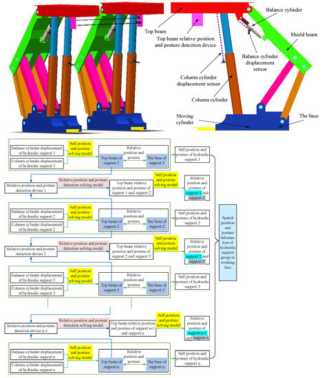
Figure 1.
Schematic diagram of position and posture detection of hydraulic support group.
2.1. Self-Pose Solving Model of Hydraulic Support
When studying the position of the hydraulic support itself, the number of degrees of freedom of the hydraulic support is analyzed to determine the dimension of the control variable. The degree of freedom of hydraulic support can be calculated according to GK formula [26] as shown in Equation (1).
where F is the degrees of freedom of the system; n is the number of elements of the system; m is the number of motion pairs; fi is the relative degrees of freedom of the i-th motion pair; v is the redundant constraints of the system; q is the number of local degrees of freedom of the system.
It can be seen from Equation (1) that this type of hydraulic support has two degrees of freedom, and the balance cylinder and column cylinder are taken as the testing objects. The current position of the hydraulic support can be obtained by calculating the posture control schematic diagram of the hydraulic support, as shown in Figure 2.
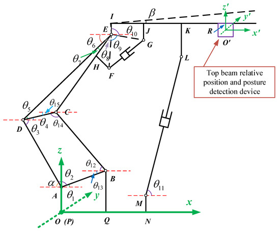
Figure 2.
Schematic diagram of hydraulic support posture control.
Based on this, the coordinates of each hinged point of the hydraulic support can be expressed in which point A, point B, point M, point P, point Q and point N are fixed points, and their coordinate values are as follows: the coordinate of point P is , the coordinate of point Q is , the coordinate of point N is , the coordinate of point A is , the coordinate of point B is , and the coordinate of point M is . Next, the coordinates of the active point will be solved.
Point C is the hinged point between the front rocker and the shield beam, and its coordinates are shown in Equation (2).
where is the angle between front rocker and horizontal plane.
Point D is the hinged point between the rear rocker and the shield beam, and its coordinates are shown in Equation (3).
where is the angle between the rear rocker and the negative direction of the x axis.
Point E is the hinged point between the top beam and the shield beam, and its coordinates are shown in Equation (4).
where is the angle between the connecting rod CD and the positive direction of the x axis; is the angle between the connecting rod DE and the connecting rod DC.
Point F is the hinge point between the balance cylinder and the shield beam, and its coordinates are shown in Equation (5).
where is the angle between the connecting rod ED and the negative direction of the x axis; is the angle between the connecting rod ED and the connecting rod EC; is the angle between the connecting rod EC and the connecting line EF.
Point G is the hinge point between the balancing Jack and the jacking beam, and its coordinates are shown in Equation (6).
where is the angle between the connecting rod EG and the connecting rod EF.
Point H is the fixed point between the connecting rod HF and the shield beam, and its coordinates are shown in Equation (7).
The coordinates of point I are shown in Equation (8).
where is the angle between the connecting rod EI and the connecting rod EG.
The coordinates of point J are shown in Equation (9).
where is the angle between the top beam and the positive direction of the x axis.
The coordinates of point K are shown in Equation (10).
The coordinates of point L are shown in Equation (11).
where is the angle between the column cylinder ML and the positive direction of the x axis.
The coordinates of point R are shown in Equation (12).
Point is the origin of the coordinate system of the top beam relative position and posture detection device, and its coordinates are shown in Equation (13).
Suppose . According to the knowledge of trigonometric functions and algebraic geometry, it can be expressed as Equation (14) to Equation (23).
According to the Euler Formula (26),
Equations (24) and (25) are simplified, respectively, and Equations (27) and (28) can be obtained.
When the real part and the imaginary part are equal, respectively, in Equation (27), Equation (29) can be obtained.
When the real part and the imaginary part are equal, respectively, in Equation (28), Equation (30) can be obtained.
The above equations can be combined to obtain the system of equations shown in Equation (31)
where , , , are known position angles, , , , , , , and are displacement and position angles to be measured. Displacement sensors are used to measure the displacement of bracket posts and balance cylinders, so and can be known. Equation (31) is a set of nonlinear equations about (, , , , , ). When Equation (31) is solved, the position of the hydraulic support itself can be obtained, and the relative-pose detection of two adjacent hydraulic supports can be realized.
2.2. Relative-Pose Solving Model of Hydraulic Support
When taking the top beam of hydraulic support as the research object, a hydraulic support is selected as the reference support, and the adjacent support is the hydraulic support to be tested. The fixed coordinate system is established on the top beam of the reference hydraulic support, and the top beam of the hydraulic support to be tested is defined as points P, A, B, respectively. If the coordinates of points P, A and B in the fixed coordinate system can be solved, the position and posture of the hydraulic support relative to the reference hydraulic support can be obtained. The principle diagram of the top beam position and posture detection of the hydraulic support is shown in Figure 3.
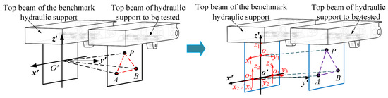
Figure 3.
Schematic diagram of detecting the relative position and posture of the top beam of hydraulic support.
The coordinates of points P, A, B can be obtained through calculating the module length and bearing of the vectors , , . Based on the existing technology, it is not convenient to solve the mode length and bearing of three vectors at the same time. In that way, three coordinate systems are established on the top beam of the benchmark hydraulic support, which are defined as coordinate, coordinate and coordinate, and each coordinate system solves a vector, respectively. After calculating the coordinates of points P, A and B in their respective coordinate systems, they can be transformed into the fixed coordinate system by coordinate transformation from which the coordinates of points P, A and B can be obtained.
As shown in Figure 4, taking the solution of the point P coordinate in as an example, the angle between the projection of the vector in the plane and the y axis is defined as the angle . The angle between the projection of in the plane and the y axis as the angle . The module length of the vector is . Then, the vector coordinates are uniquely determined by them, and the coordinate solution formula of point P is as shown in Equation (32)
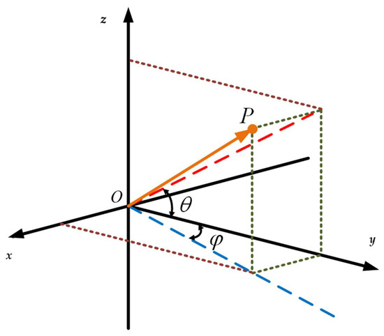
Figure 4.
Schematic diagram of solving point P coordinates.
The coordinates of point P are defined as , the coordinates of point A are , and the coordinates of point B are . When only the coordinate translation transformation is considered and the rotation transformation is not considered, the coordinate solution formulas of points P, A and B are as follows:
where Matrix D is shown in Equation (34)
In the formula, , and are respectively the deflection angles of points P, A and B around the x-axis, and , and are the deflection angles of points P, A and B around the y axis, respectively. From Equation (33), the coordinates of points P, A and B in the coordinate system can be obtained and then the relative positions of the top beam of the hydraulic support and the top beam of the reference hydraulic support can be obtained.
3. Position and Posture Detection and Control System of Hydraulic Support
Based on the mathematical model of hydraulic support pose detection, the pose detection and control system is constructed (as shown in Figure 5). The system mainly consists of the power source of the hydraulic support (pump station and pump station control cabinet), hydraulic support body, pose detection device, signal acquisition device, PC host computer and signal conversion device, intelligent control cabinet of hydraulic support, manual or automatic switching controller of hydraulic support, etc. The process of the hydraulic support position and posture detection and control system is as follows: the position and posture detection device collects the data of the angle sensor and the displacement sensor and transmits them to the MCU. After MCU processing, send the result to the PC host computer. The upper computer runs the mathematical model of the position and posture detection to solve the position. After obtaining the relative position and posture of the support, the current position and posture of the support is displayed on the human–computer interface and compared with the position and posture preset by the host computer. At the same time, the pose error is determined, and the control scheme is chosen. The control information is fed back to the control system to realize the automatic correction and adjustment of the position and posture of the hydraulic support. In order to realize the above process, the physical model should be established first and then the more suitable position and posture solution method and control method of the hydraulic support should be selected.
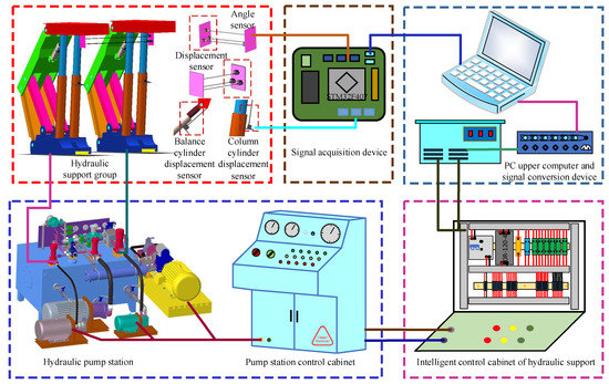
Figure 5.
Schematic diagram of detection and control system of hydraulic support.
3.1. Establishment of Physical Model
According to the mathematical model of the position and posture detection of the hydraulic support, we chose the AS40S6 single-turn absolute type encoder produced by Alwayi manufacturer to measure the angle and the pull wire displacement sensor to measure the length. The specific parameters are shown in Table 1 and Table 2.

Table 1.
Specific parameters of the absolute encoder.
Table 2.
Pull-wire sensor parameters.
An STM32F407 chip is used as the main controller for position and posture detection. The GPIO pin of the chip controls the corresponding components to realize the communication function between the MCU and hydraulic support controller. The position and posture detection signal acquisition board is designed with seven data interfaces of displacement sensors, six data interfaces of angle sensors, a “parameter enable” port, and a “origin enable” port. The hydraulic support controller is controlled by the two-stage relay produced by Schneider, and the optocoupler TLP521-1 was selected to isolate the circuit to avoid interference. The specific parameters are shown in Table 3 and Table 4:
Table 3.
Parameters of optocoupler switch.
Table 4.
Relay parameter description.
3.2. Position and Posture Solution Method
When solving the position of hydraulic support, the traditional numerical analysis method can not meet the needs. In this paper, particle swarm optimization algorithm is used to solve the nonlinear equations. Kennedy and Eberhart presented the particle swarm optimization algorithm [27,28]. In the process of seeking optimal solution, the individual can be seen as a quality and volume but no speed and position “particles”. The process of particle optimization in space is shown in Equations (35) and (36):
where represents the velocity of “particle i” at the kth iteration in the d-dimensional space; represents the position of “particle i” at the kth iteration in the d-dimensional space. and are random numbers; c1 and c2 are acceleration factors; represents the best solution of all particles saved in the process of seeking the optimal solution. refers to the optimal solution obtained by the particle itself in the process of seeking the optimal solution. represents inertia weight [29].
The nonlinear equations can be described as shown in Equation (37)
where X = (x1, x2, x3, x4, x5, x6) = (α, β, θ6, θ11, θ12, θ15), and define the fitness function as . Then, the problem can be transformed into solving the minimum value of , that is,
When , the corresponding X is the solution of the nonlinear equations system.
The hydraulic support ZY21000/38/82 is used to test the solving method of position and posture of hydraulic support. The range of the rotation angle of the rear connecting rod α is (0.62,1.38). The range of the pitch angle of the top beam β is (−0.35, 0.35). The range of the angle between the shield beam and the horizontal direction θ6 is (0.17,1.22). The range of the angle between the column and the horizontal direction θ11 is (0.69, 1.39). The range of the angle between the front connecting rod and the horizontal direction θ12 is (0.52, 0.96). The range of the angle between the line that is connected the front connecting rod and the rear connecting rod and the horizontal direction θ15 is (0.35, 0.87).
The displacement data of column and balance cylinder are selected to test the algorithm. The length of the column and balance cylinder is LML = 1248 mm, LFG = 332 mm. The first step is to record the optimal solution obtained by the particle swarm optimization algorithm and then to analyze the calculation accuracy. The result of the particle swarm optimization algorithm calculation test I is shown in Figure 6. Figure 6a shows the change of fitness function from which it can be seen that the particle swarm optimization algorithm has a good convergence effect for the system of nonlinear equations, and the optimal solution can be achieved after approximately 150 iterations; (b) shows the change of the optimal value of each attitude angle from which it can be seen that the particle swarm optimization algorithm is ideal for solving the optimal solution, and there are small range fluctuations among calculated value and real value.
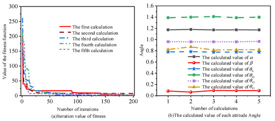
Figure 6.
Experimental results of test I calculated by particle swarm optimization algorithm. (a) shows the change of fitness function in the calculation process of particle swarm optimization algorithm for 5 times. (b) shows the changes of the optimal values of each attitude Angle obtained by 5 calculations.
The experimental data of hydraulic support pose solution test I based on particle swarm optimization algorithm are shown in Table 5. According to the analysis in Table 5, the maximum error ratio of position angle solution is 2.2%, the minimum error ratio is 0.076%, and the average value of maximum error ratio is 0.559%. The solution accuracy can well meet the application requirements.
Table 5.
TestI of hydraulic support pose solution based on particle swarm optimization algorithm.
3.3. Control Method of Hydraulic Support
Bang-Bang control was first proposed by Pontriagin, which is essentially a kind of time-optimal control method. Its control function is on the boundary of the allowable control. As its control function is switched on the boundary, which is also called switching control.
The general form of the Bang-Bang State Control Equation [30] is shown in Equation (39):
where represents an N-dimensional state vector, represents r-dimensional control vector, represents N-dimensional vector function.
The cylinder position control can be described as the shortest time problem of a linear time-invariant system, and the given control system is shown in Equation (40).
where represents order matrix; represents order matrix; represents n-dimensional state vector, represents m-dimensional control vector, the value range of is [−1, 1], p = 1, 2, 3…
Find the control function so that Equation (40) can reach the origin of the state space in the shortest time under the action of the control function . The performance index of this control problem can be expressed as Equation (41).
When the control variable has clear upper and lower boundaries, Equation (41) can be determined, and its function value is obtained at the upper and lower boundaries.
where represents the jth column vector of matrix B.
The core of the time-optimal control is Bang-Bang control, is a piecewise constant value function, which switches back and forth between +1 and −1. The switching time point is:
As can be seen from Equation (44), the function switches back and forth on +1 and −1 in the control process, which is similar to the principle of the valve-controlled hydraulic cylinder.
The key to the position control of the hydraulic support is to realize the accurate displacement control of the hydraulic cylinder. There is a coupling relationship between the hydraulic cylinder and the load, pose detection device, attitude control device, control valve and other components. The position control diagram of the hydraulic cylinder is shown in Figure 7.
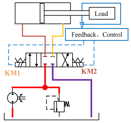
Figure 7.
Schematic diagram of hydraulic cylinder displacement control.
The relationship between the length of the reference cylinder and the cylinder to be tested is shown in Equation (45).
where D represents the displacement difference of the cylinder length; represents the displacement of the hydraulic cylinder preset by the system; represents the displacement of the corresponding cylinder on the hydraulic support to be adjusted.
According to the principle of Bang-Bang control, the support cylinder control strategy is shown in Equation (46)
when , the system is in position mode 1, which indicates the cylinder moves quickly, while in , the cylinder moves fast forward, and in , the cylinder moves in the opposite direction. L2 represents threshold 2, and when , the system is in positioning mode 2, which indicates the cylinder moves at medium speed, and approaches the predetermined position at a faster speed. Ε represents the preset error of the system, and when , the cylinder completes the positioning operation, and stops working. When , the system is in the positioning mode 3, which indicates the cylinder approaches the predetermined position at a slower speed.
4. Experimental Research on Intelligent Control of Hydraulic Support Based on Position and Posture Detection
The intelligent control experiment of hydraulic support based on position and posture detection is completed on the developed three-machine intelligent control simulation experimental platform of the working face, as shown in Figure 8.
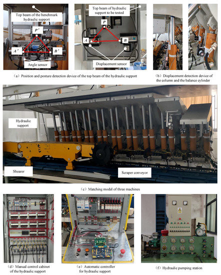
Figure 8.
Hydraulic support relative position and posture detection experimental platform.
In Figure 8, (a) shows the position and posture detection device of the top beam of the hydraulic support; (b) describes the displacement detection device of the column and the balance cylinder; (c) shows the matching model of three machines, including the hydraulic support, the shearer and the scraper conveyor; (d) displays the manual control cabinet of the hydraulic support; (e) illustrates automatic controller for hydraulic support, including main controller, position and posture detection signal acquisition device, signal acquisition card and hydraulic support controller, etc.; and (f) shows the hydraulic pumping station.
4.1. Sampling Experiment of Hydraulic Support Based on Position and Attitude Detection
The movement of the hydraulic support mainly depends on the cooperation of the column, the balance cylinder and the moving cylinder, and the motion status of the cylinder also determines the position and posture of the hydraulic support. In order to analyze the motion characteristics of the cylinder, firstly, sample collection experiments are carried out on the movement of hydraulic support column cylinder, balance cylinder and push cylinder. The sample collection experiment diagram of hydraulic support is shown in Figure 9.
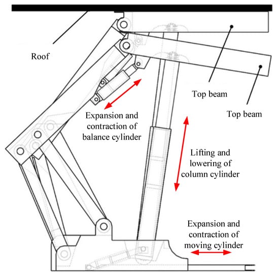
Figure 9.
Schematic diagram of sample collection experiment of hydraulic support.
4.1.1. Displacement Sample Collection Experiment of Hydraulic Support Column Cylinder
The sample collection experiment of column cylinder is shown in Figure 10.
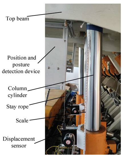
Figure 10.
Sample collection experiment of column cylinder.
The experiment is divided into two parts: the rising column movement and the falling column movement. The opening time of the column control valve is set, and the displacement of the column is analyzed when the time interval is s, s and s.
The displacement of the column lifting movement changes with time variation curves shown in Figure 11. The analysis of Figure 11 reveals that in the process of column lifting movement, when the control valve is electrified for 0.1 s, the displacement of the cylinder is approximately 5 mm, 18 mm when it is electrified for 0.5 s and 37 mm for 1 s.
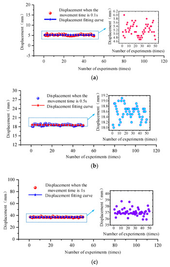
Figure 11.
Variation curve of displacement with time during column lifting movement of the column cylinder of hydraulic support. (a) shows the displacement fitting curve under the condition of multiple experiments and movement time of 0.1 s; (b) shows the displacement fitting curve under the condition of multiple experiments and movement time of 0.5 s; (c) shows the displacement fitting curve under the condition of multiple experiments and movement time of 1 s.
The analysis of Figure 12 reveals that in the process of column falling movement, when the control valve is electrified for 0.1 s, the displacement of the cylinder is approximately 5.4 mm, 15 mm when it is electrified for 0.5 s and 27 mm for 1 s.
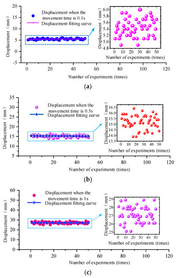
Figure 12.
Variation curve of displacement with time during column lowering movement of the column cylinder of hydraulic support. (a) shows the displacement fitting curve under the condition of multiple experiments and movement time of 0.1 s; (b) shows the displacement fitting curve under the condition of multiple experiments and movement time of 0.5 s; (c) shows the displacement fitting curve under the condition of multiple experiments and movement time of 1 s.
4.1.2. Displacement Sample Collection Experiment of Hydraulic Support Balance Cylinder
The sample collection experiment of the hydraulic support balance cylinder is divided into two parts: the cylinder protruding and retracting. The sample collection experiment of the balance cylinder is shown in Figure 13.
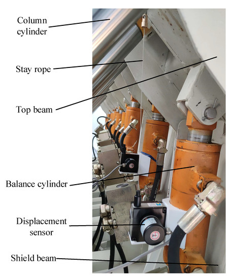
Figure 13.
Sample collection experiment of the balanced cylinder of hydraulic support.
Set the opening time of the balance cylinder control valve; the displacement of the balance cylinder should be measured. As the stroke of the balance cylinder is shorter and the cylinder diameter is smaller, its displacement is larger in the same action time, and this section only studies the displacement of the balance cylinder at s. The displacement data of the hydraulic support balancing cylinder in protruding motion and retraction motion are shown in Figure 14 and Figure 15, respectively.
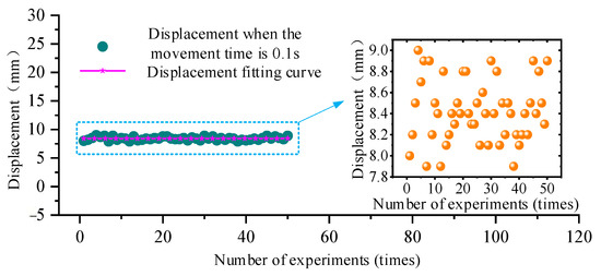
Figure 14.
Variation curve of displacement with time during extension movement of the balance cylinder of hydraulic support.
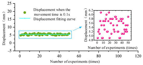
Figure 15.
Variation curve of displacement with time during retraction of the balance cylinder of hydraulic support.
According to the analysis of Figure 14 and Figure 15, when the control valve of the balance cylinder of the hydraulic support is electrified for 0.1 s, the displacement of the balance cylinder in the protruding motion is approximately 8.4 mm, and the displacement of the balance cylinder in retraction motion is approximately 5.4 mm.
4.1.3. Displacement Sample Collection Experiment of Hydraulic Support Moving Cylinder
The schematic diagram of the pushing action of the hydraulic support is shown in Figure 16, which converts the displacement of the measuring cylinder into the displacement of the measuring push rod.
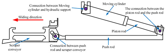
Figure 16.
Schematic diagram of cylinder moving of hydraulic support.
Similar to the sample collection experiment of the balanced cylinder, the sample collection of the push cylinder is divided into two parts: the push rod protruding and the push rod retracted, and it is only the displacement of the cylinder that is measured at s. The sample collection experiment of the push cylinder is shown in Figure 17.
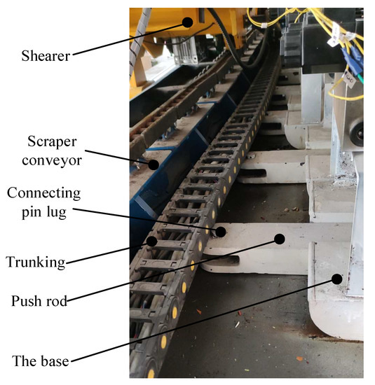
Figure 17.
Sample collection experiment of the moving cylinder of hydraulic support.
The opening time of the control valve of the push cylinder is set, and the displacement of the cylinder at s is analyzed. The displacement data of the cylinder in the protruding motion and retraction motion are shown in Figure 18 and Figure 19, respectively.
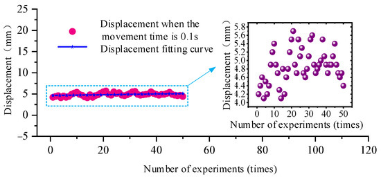
Figure 18.
Variation curve of displacement with time during extension movement of the pushing cylinder of hydraulic support.
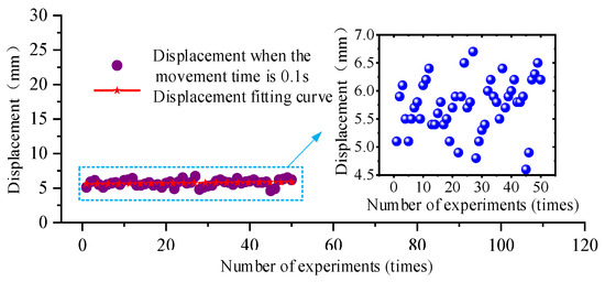
Figure 19.
Variation curve of displacement with time during retraction of the pushing cylinder of hydraulic support.
According to the analysis of Figure 18 and Figure 19, when the control valve of the push cylinder is electrified for 0.1 s, the displacement of the cylinder with the push rod protruding is approximately 8.4 mm, and the displacement of the cylinder with the push rod retracted is approximately 5.4 mm.
Through the displacement sample collection experiment of the hydraulic support column cylinder, the balance cylinder and moving cylinder in unit time, the displacement characteristics of each cylinder of the hydraulic support are determined, which lays a foundation for realizing the accurate position and posture control of the hydraulic support.
4.2. Motion Control Experiment of Hydraulic Support Based on Position and Posture Detection
4.2.1. Following Motion Experiment of the Hydraulic Support
After determining the motion characteristics of the hydraulic support cylinder, the following motion experiment of the hydraulic support is carried out to test and calibrate the motion accuracy. The reference hydraulic support is selected as “manual” mode, and the support to be tested is selected as “automatic” mode. The following motion diagram of hydraulic support is shown in Figure 20. The test includes the following motion test of the column cylinder, balance cylinder and moving cylinder.
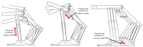
Figure 20.
Schematic diagram of hydraulic support following motion.
The following motion experiment of the column cylinder: firstly, set the balance cylinder and the moving cylinder of the two supports to remain motionless and control the column cylinder of the reference support to move 50 mm, 100 mm, 150 mm and 200 mm. Then, measure and analyze the displacement of the following motion column cylinder to be tested. The following motion experiments of the column cylinder of hydraulic support is shown in Figure 21.
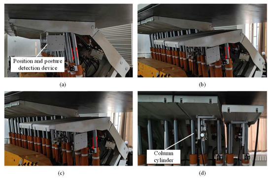
Figure 21.
Following motion experiment of the column cylinder of hydraulic support. (a–d) shows the position of the column cylinder and the expansion trajectory.
The following motion experiment of the balance cylinder: firstly, set the column and moving cylinder of the two supports to remain motionless, control the balance cylinder of the reference support for 20 mm, 40 mm, 60 mm and 80 mm. Then, measure and analyze the displacement of the balance cylinder of the support to be tested in the following motion. The following motion experiments of the balancing cylinder of hydraulic support is shown in Figure 22.
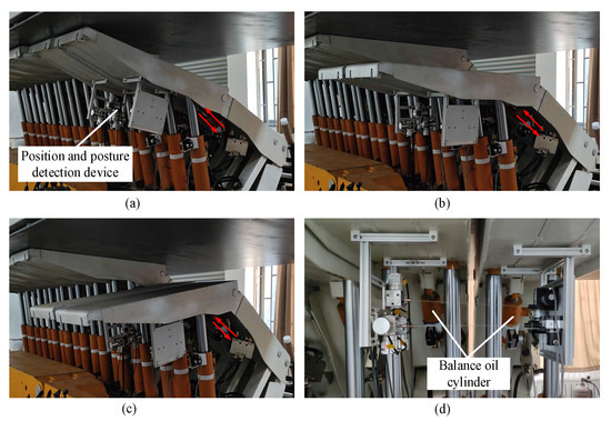
Figure 22.
Following motion experiment of the balancing cylinder of hydraulic support. (a–d) shows the position of the balancing cylinder and the expansion trajectory.
The following motion experiment of the moving cylinder: firstly, set the column and balance cylinder of the two supports to remain motionless, control the moving cylinder of the reference support to move 20 mm, 40 mm, 40 mm, 60 mm and 80 mm. Then, measure and analyze the displacement of the moving cylinder of the support to be tested in the following motion. The following motion experiments of the pushing cylinder of hydraulic support is shown in Figure 23.
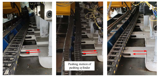
Figure 23.
Following motion experiment of the pushing cylinder of hydraulic support.
The displacement curves of the column cylinder of hydraulic support are shown in Figure 24. According to the analysis of the column cylinder displacement curve shown in Figure 24, the positioning error is ±2 mm when the column cylinder displacement of the reference support is set to 50 mm, from −2 mm to +3 mm when the moving displacement is set to 100 mm, from −3 mm to + 2 mm when the moving displacement is set to 150 mm, and ±2 mm when the moving displacement is set to 200 mm.
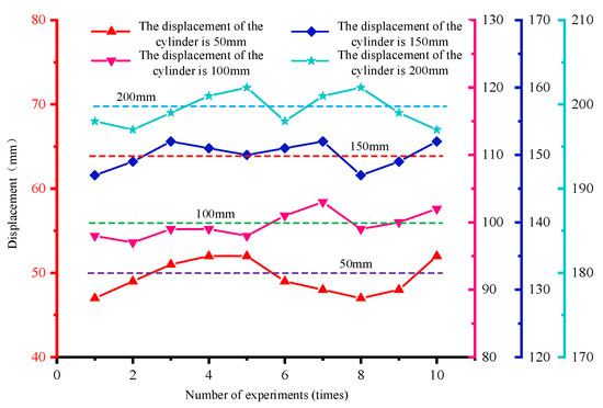
Figure 24.
Displacement curve of the column cylinder of hydraulic support.
The displacement curves of the balancing cylinder of hydraulic support is shown in Figure 25. According to the analysis of the balance cylinder displacement curve shown in Figure 25, the positioning error is ±2 mm when the balance cylinder displacement of the reference support is set to 20 mm, from −3 mm to +2 mm when the moving displacement is set to 20 mm, ±2 mm when the moving displacement is set to 60 mm, and from −1 mm to +2 mm when the moving displacement is set to 80 mm.
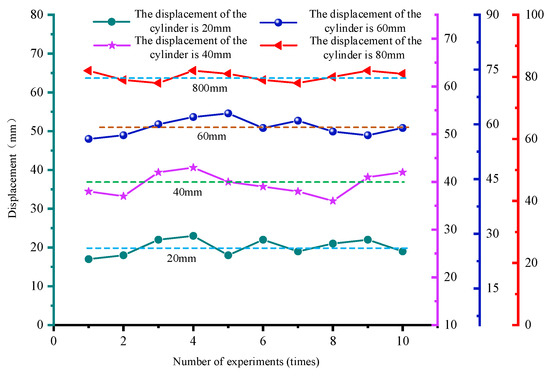
Figure 25.
Displacement curve of the balancing cylinder of hydraulic support.
The displacement curves of the pushing cylinder of hydraulic support is shown in Figure 26. According to the analysis of the moving cylinder displacement curve shown in Figure 26, the positioning error is ±2 mm when the moving cylinder displacement of the reference support is set to 20 mm, ±2 mm when the moving displacement is set to 20 mm, from −1 mm to +2 mm when the moving displacement is set to 60 mm, and from −3 mm to +2 mm when the moving displacement is set to 80 mm.
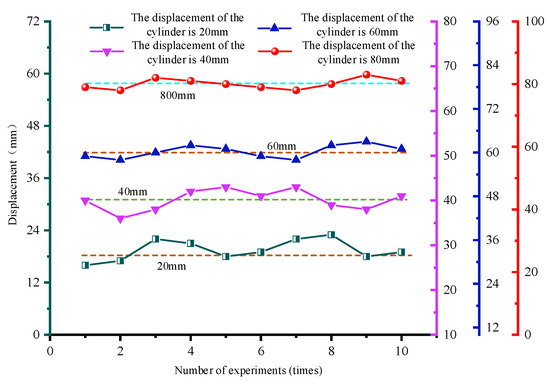
Figure 26.
Displacement curve of the pushing cylinder of hydraulic support.
Through the following motion experiment of each cylinder of the hydraulic support, it is known that the positioning accuracy of the experiments obtained by this experimental platform is high, which meets the requirements of field use.
4.2.2. Hydraulic Support Autonomous following Machine Simulation Experiment
In order to test the hydraulic support position and posture detection device and support control system, the hydraulic support autonomous following simulation experiment is carried out. The experimental process is as follows: the reference support is set to “manual” mode, and the support to be tested is set to “automatic” mode. In the first step: the reference support pushes the scraper conveyor 50 mm; in the second step: the column reduces the 100 mm, and the balance cylinder retracts 30 mm; in the third step: the moving cylinder extends 50 mm in the direction of the scraper conveyor; and in the fourth step: the column and the balance cylinder work at the same time so that the top beam of the reference support is fully topped. After waiting for the completion of the reference support operation, the tested support begins to independently follow the machine. Firstly, measure and record the position of the hydraulic support to be tested, and observe the pose image display interface of the hydraulic support intelligent control system. The process of autonomous machine following experiment of hydraulic support is shown in Figure 27.
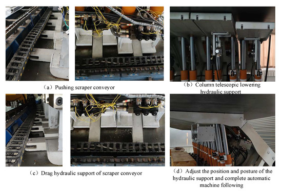
Figure 27.
Autonomous following experiment of hydraulic support. (a) shows pushing scraper conveyor. (b) shows column telescopic lowering hydraulic support. (c) shows drag hydraulic support of scraper conveyor. (d) shows adjust the position and posture of the hydraulic support and complete automatic machine following.
The upper computer in the experiment runs the mathematical model of posture detection and draws the current position of the support in Visual Studio. The position and posture of the hydraulic support at a certain time in the movement process is displayed through the online display interface of the intelligent control system of hydraulic support, as shown in Figure 28.
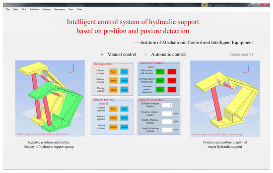
Figure 28.
Online display interface of hydraulic support intelligent control system.
The position and posture of the hydraulic support base directly affects the straightness of the hydraulic support group and then affects the straightness of the scraper conveyor. Taking the displacement of the front end face of the hydraulic support base as the evaluation standard of the hydraulic support autonomous following machine. The displacement data of the hydraulic support base is shown in Figure 29.
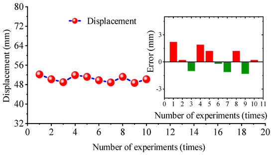
Figure 29.
Displacement data of hydraulic support base.
According to the analysis of Figure 29, after the support to be test automatic following, the intelligent control system can automatically adjust the position of the hydraulic support based on the position and posture detection device. After experiments for 10 times, the displacement of the hydraulic support base fluctuates between 48.7 mm−52.2 mm and the positioning error is −1.3 mm to +2.2 mm, which can meet the needs of actual production in the actual working environment of the coal mine.
5. Conclusions
- Based on the position and posture relationship of two adjacent hydraulic supports and the structural characteristics of the support itself, the mathematical model of relative-pose detection of hydraulic support is established, which provides a theoretical basis for the design of a relative-pose detection device of hydraulic support;
- The particle swarm optimization algorithm is used to solve the position model of hydraulic support, and ZY21000/38/82 hydraulic support is calculated and tested. The test results show that the average maximum error ratio of the algorithm is 0.559%, which can meet the needs of hydraulic support pose detection. The cylinder position control strategy based on Bang-Bang control algorithm meets the position and posture control requirements of the existing hydraulic support and can realize the closed-loop feedback control of the hydraulic support;
- In order to test the hydraulic support position and posture detection device and the hydraulic support automatic control system, the following motion experiment and the following autonomous experiment of the hydraulic support cylinder are carried out with the help of the hydraulic support cylinder sample collection experiment. The experimental results show that the maximum motion positioning error of the hydraulic support moving cylinder is 2.2 mm, and the hydraulic support can follow the machine independently under the action of the intelligent control system, which verifies the feasibility and accuracy of the hydraulic support intelligent control system based on position and posture detection.
The research on the position and posture detection and intelligent control system of hydraulic support provides a train of thought for the straightness detection and automatic control of working face equipment, provides a theoretical support for solving the independent correction and intelligent decision of hydraulic support in the future, and lays a foundation for the development of automatic and intelligent mining technology of coal mines. In view of the limitations of the author’s ability and research time, the following problems remain to be solved in this subject. The future work is as follows:
- (1)
- This topic is to study the position and posture detection and intelligent control of two adjacent hydraulic supports. At present, it is not possible to realize the monitoring of the working face support group. In the future, data fusion can be considered for the pressure of each cylinder of the support, the pressure of each component, the force and deformation of the key hinge point of the support and other parameters, so as to truly realize the intelligent control of the hydraulic support;
- (2)
- The hardware and software system built by this subject has not considered the safety requirements of explosion-proof and dust-proof underground coal mines. In the future, the actual working environment of the hydraulic support should be fully considered, and the necessary safety measures, such as dust-proof and explosion-proof, should be taken.
Author Contributions
Conceptualization, Y.Z., K.G., J.C. and Q.Z.; methodology, H.Z. and K.G.; software, H.Z.; validation, H.Z. and K.G.; formal analysis, H.Z.; writing—original draft preparation, Y.Z. and K.G.; writing—review and editing, Y.Z. and F.M.; supervision, Y.Z., K.G. and Q.Z. All authors have read and agreed to the published version of the manuscript.
Funding
This work was supported by the National Natural Science Foundation of China Program (No. 51974170 and No. 52274132) and the Shandong Provincial Key Research and Development Project (No. 2019SDZY01).
Institutional Review Board Statement
Not applicable.
Informed Consent Statement
Informed consent was obtained from all subjects involved in the study.
Data Availability Statement
All data is from the experiment and no external data is involved.
Conflicts of Interest
The authors declare no conflict of interest.
Abbreviation
The interpretation of symbols in formulas.
| Symbol | meaning |
| Relay_control | The motion state of the valve |
| (keep_on)+ | The movement mode of the valve is 01, that is, the control valve is open in the positive direction |
| (keep_on)− | Valve motion mode 02, that is, the control valve is normally open in the reverse |
| (on_and_off_1)+ | The movement mode of the valve is 11, that is, the valve controls the forward movement of the cylinder with mode 1 |
| (on_and_off_1)− | The movement mode of the valve is 12, that is, the valve controls the reverse movement of the cylinder with mode 1 |
| (on_and_off_2)+ | The movement mode of the valve is 21, that is, the valve controls the forward movement of the cylinder with mode 2 |
| (on_and_off_2)− | The movement mode of the valve is 22, that is, the valve controls the reverse movement of the cylinder with mode 2 |
| off | The movement mode of the valve is 3, that is, the valve stops and the cylinder stops moving |
| L1 | Indicates the threshold value 1 |
References
- Fu, X.; Wang, R.; Zhao, Y. Intelligent decision-making model on the of hydraulic supports group advancing behavior to follow shearer. China Coal Soc. 2020, 45, 2065–2077. [Google Scholar]
- Sandstrom, K.; Norstrom, C. Managing complex temporal requirements in real-time control system: Engineering of computer-based systems. In Proceedings of the Ninth Annual IEEE International Conference and Workshop on the Engineering of Computer-Based Systems, Lund, Sweden, 8–11 April 2002; pp. 103–109. [Google Scholar]
- Young, C.P.; Juang, W.L.; Devaney, M.J. Real-time intranet-controlled virtual instrument multiple-circuit power monitoring. IEEE Trans. Instrum. Meas. 2000, 49, 579–584. [Google Scholar] [CrossRef]
- Lu, T.; Ma, P.; Feng, Z. Design on Posture Dynamic Monitoring and Control System of Hydraulic Support. Coal Sci. Technol. 2014, 42, 169–172. [Google Scholar]
- Liang, M.; Fang, X.; Li, S.; Wu, G.; Ma, M.; Zhang, Y. A fiber Bragg grating tilt sensor for posture monitoring of hydraulic supports in coal mine working face. Measurement 2019, 138, 305–313. [Google Scholar] [CrossRef]
- Wang, X.W.; Xie, J.C.; Hao, S.Q.; Li, J.L.; Yang, Z.J.; Ren, F.; Bao, Q.B. Key technologies of real-time virtual monitoring method for an intelligent fully mechanized coal-mining face. J. China Coal Soc. 2020, 45, 1984–1996. [Google Scholar]
- Xie, J.; Wang, X.; Yang, Z.; Hao, S. Attitude-aware method for hydraulic support groups in a virtual reality environment. Proc. Inst. Mech. Eng. Part C-J. Mech. Eng. Sci. 2019, 233, 4805–4818. [Google Scholar] [CrossRef]
- Lian, Z.S.; Yuan, X.; Gao, F.; Liao, Y.Y.; Guo, Y.C. Networked intelligent sensing method for powered support. J. China Coal Soc. 2020, 45, 2078–2089. [Google Scholar]
- Du, Y. Supporting condition acquisition and fuzzy comprehensive evaluation method for hydraulic support. J. China Coal Soc. 2017, 42, 260–266. [Google Scholar]
- Li, S.; Xie, J.; Wang, X.; Ren, F.; Zhang, X.; Bao, Q. Path planning of hydraulic support pushing mechanism based on extreme learning machine and descartes path planning. Symmetry 2021, 13, 97. [Google Scholar] [CrossRef]
- Hu, B. Study on the Intelligent Control System of Hydraulic Support. Ph.D. Thesis, Taiyuan University of Technology, Taiyuan, China, 2014. [Google Scholar]
- Wang, J.; Wang, Z.; Zhang, L. Research on electro-hydraulic control system of hydraulic support based on Ethernet and CAN-Bus. J. China Coal Soc. 2016, 41, 1575–1581. [Google Scholar]
- Niu, J. Study on automatic and intelligent following control system of hydraulic powered support in fully mechanized coal mining face. Coal Sci. Technol. 2015, 43, 85–91. [Google Scholar]
- Mao, J.; Guo, H.; Guo, J. Research on hydraulic support slip system based on fuzzy sliding mode control. Meas. Control. Technol. 2017, 36, 67–70. [Google Scholar]
- Wang, G.; Pang, Y.; Ren, H. Intelligent coal mining pattern and technological path. J. Min. Strat. Control. Eng. 2020, 2, 5–19. [Google Scholar]
- Hu, X. Cooperative automatic control for the canopy posture of a four-leg hydraulic support. Int. J. Simul. Model. 2020, 19, 713–724. [Google Scholar] [CrossRef]
- Song, H. Design of Intelligent Shift Control System for Coal Mine Hydraulic Support. Mech. Electr. Eng. Technol. 2019, 48, 49–51. [Google Scholar]
- Zhang, S. Research on Straightness Measurement Method of Hydraulic Support Based on Multi-Sensor Fusion. Master’s Thesis, Xi’an University of Science and Technology, Xi’an, China, 2020. [Google Scholar]
- Fan, Q.; Li, W. Research on Equipment Positioning and Task Coordination in “Three Machines” Control of Fully Mechanized Face. J. Mech. Eng. 2015, 51, 152. [Google Scholar]
- Yan, H. Study on Key Technology of Hydraulic Support Virtual Monitoring System. Ph.D. Thesis, China University of Mining and Technology, Xuzhou, China, 2011. [Google Scholar]
- Hu, B.; Lian, Z. Study on Hydraulic Support Straightening System Based on Support Vector Machine and Genetic Algorithm. Coal Mine Mach. 2014, 35, 39–41. [Google Scholar]
- Xu, X. Research on Key Technologies of Posture Monitoring for Hydraulic Support. Master’s Thesis, China University of Mining and Technology, Xuzhou, China, 2017. [Google Scholar]
- Meng, Z. Adaptability Analysis and Intelligent Control Technology of Hydraulic Support with Super-Large Mining Height. Ph.D. Thesis, Shandong University of Science and Technology, Qingdao, China, 2018. [Google Scholar]
- Gao, K.; Xu, W.; Zhang, H.; Zhang, Y.; Zeng, Q.; Sun, L. Relative position and posture detection of hydraulic support based on particle swarm optimization. IEEE Access 2020, 8, 200789–200811. [Google Scholar] [CrossRef]
- Wang, G. Theory system of working face support system and hydraulic roof support technology. J. China Coal Soc. 2014, 39, 1593–1601. [Google Scholar]
- Meng, Z.; Zeng, Q.; Wan, L.; Liu, P. Pose adjusting simulation of hydraulic support based on mechanical-electrical-hydraulic coordination. Teh. Vjesn. 2018, 25, 1110–1118. [Google Scholar]
- Kennedy, J.; Eberhart, R. Particle Swarm Optimization. In Proceedings of the Icnn95-International Conference on Neural Networks, Perth, WA, USA, 27 November–1 December 1995; IEEE: Piscataway, NJ, USA, 2002. [Google Scholar]
- Zhang, Q. Research on the Particle Swarm Optimization Algorithm and Differential Evolution Algorithm. Ph.D. Thesis, Shandong University, Jinan, China, 2017. [Google Scholar]
- León, O.D.; Aceves-Fernandez, M.A.; Fernandez-Fraga, S.M.; Ramos-Arreguín, J.M.; Gorrostieta-Hurtado, E. An improved particle swarm optimization (PSO): Method to enhance modeling of airborne particulate matter (PM10). Evol. Syst. 2019, 11, 615–624. [Google Scholar] [CrossRef]
- Huang, Z.; Guan, L.; Tu, L. Study on a Large-signal Transient Stability Controller for HVDC Based on Bang-Bang Control. High Volt. Eng. 2016, 42, 127–135. [Google Scholar]
Disclaimer/Publisher’s Note: The statements, opinions and data contained in all publications are solely those of the individual author(s) and contributor(s) and not of MDPI and/or the editor(s). MDPI and/or the editor(s) disclaim responsibility for any injury to people or property resulting from any ideas, methods, instructions or products referred to in the content. |
© 2022 by the authors. Licensee MDPI, Basel, Switzerland. This article is an open access article distributed under the terms and conditions of the Creative Commons Attribution (CC BY) license (https://creativecommons.org/licenses/by/4.0/).