

Design, Analysis and Experimental Research of Dual-Tendon-Driven Underactuated Gripper


Abstract
:1. Introduction
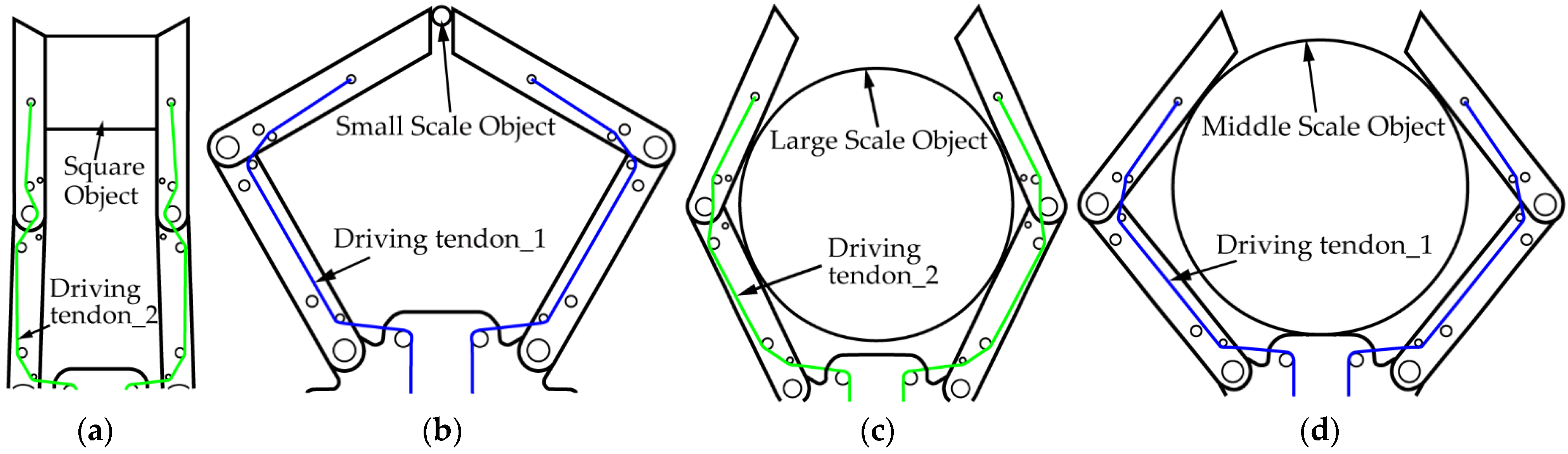
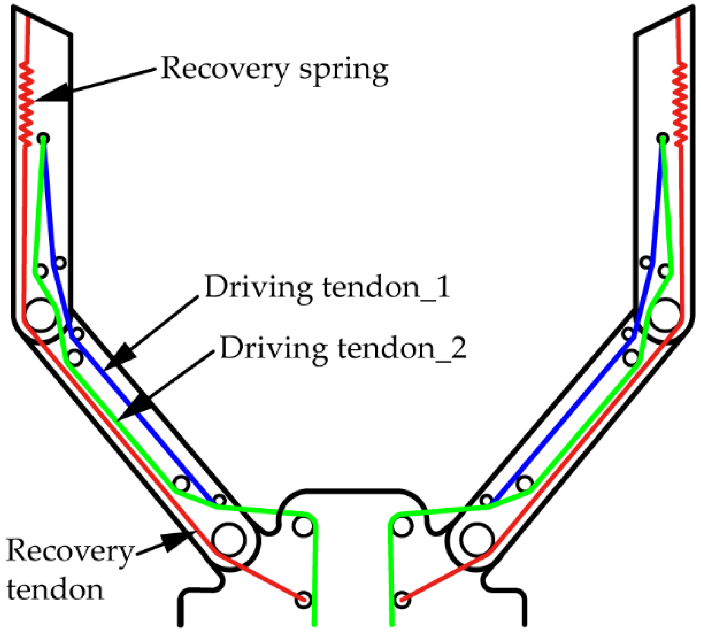
- We designed a novel dual-tendon-driven underactuated gripper, which is driven by two independent tendons with different winding paths and can achieve four kinds of clamping postures.
- We calculated and compared the resultant moments of end knuckle rotary joints driven by different tendons and analysed the conditions of knuckles moving when driven by different tendons.
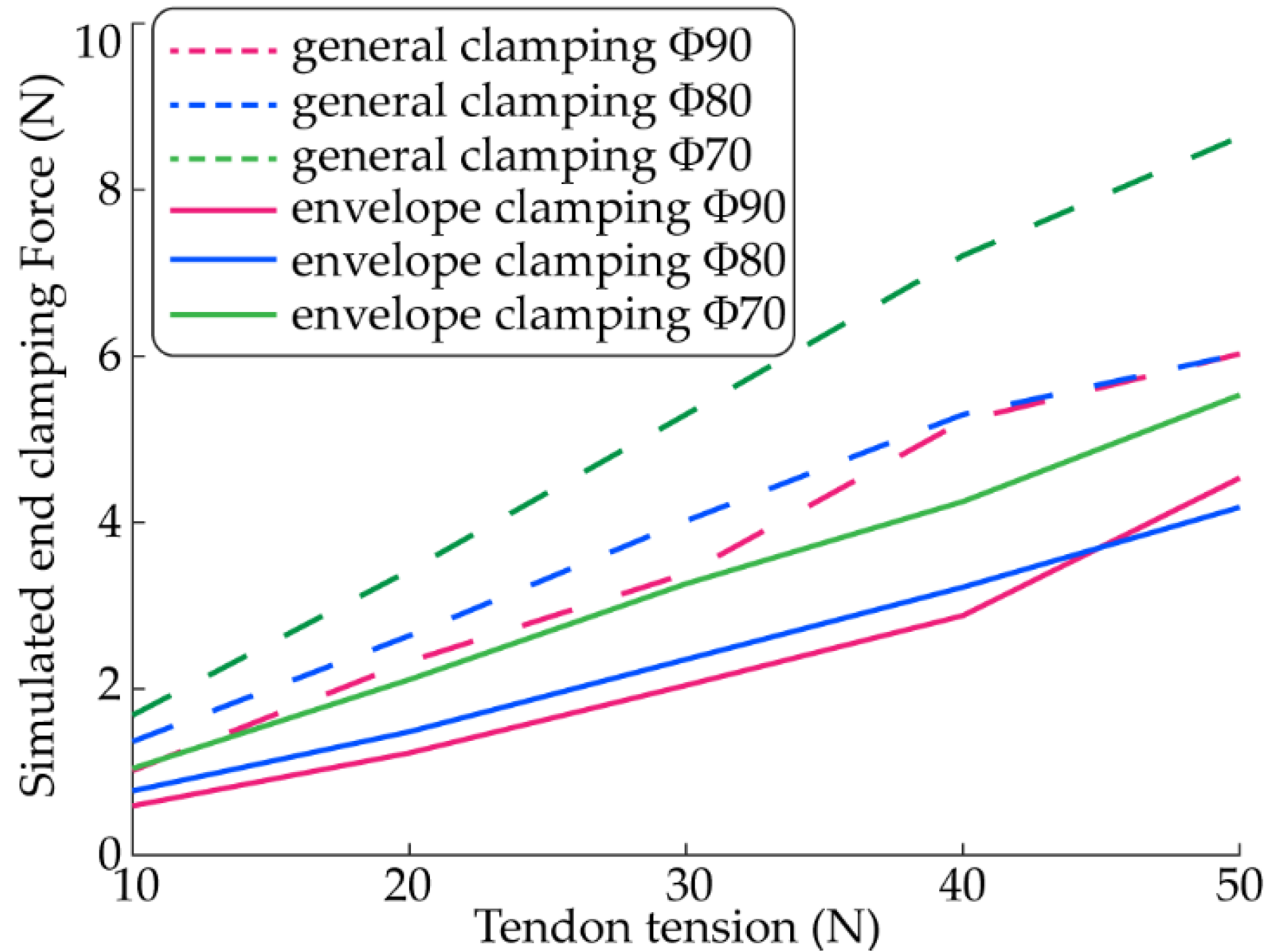
- We simulated the end clamping force and movement of gripper knuckles with different clamping postures and verified the validation of the structure and tendon winding path design.
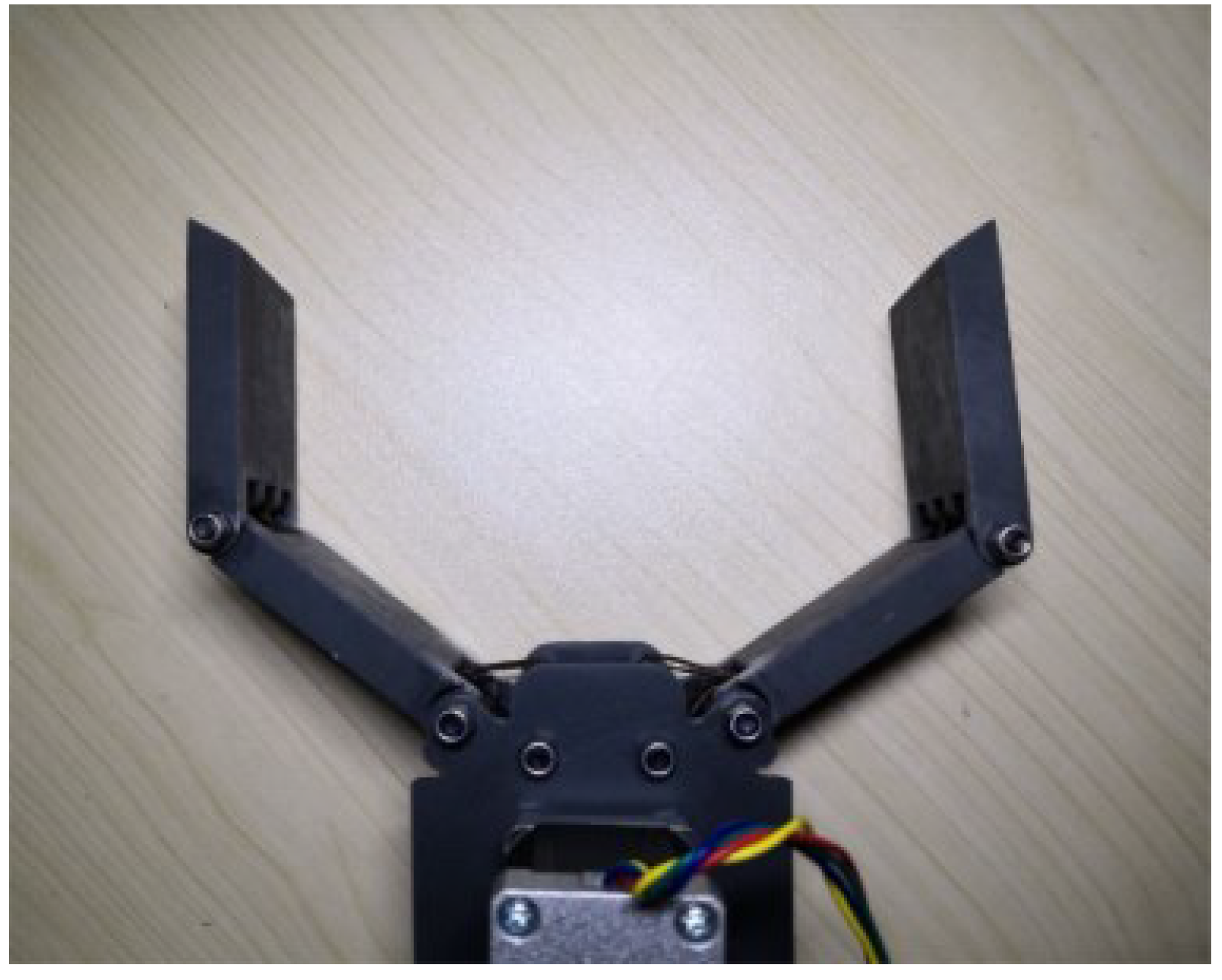
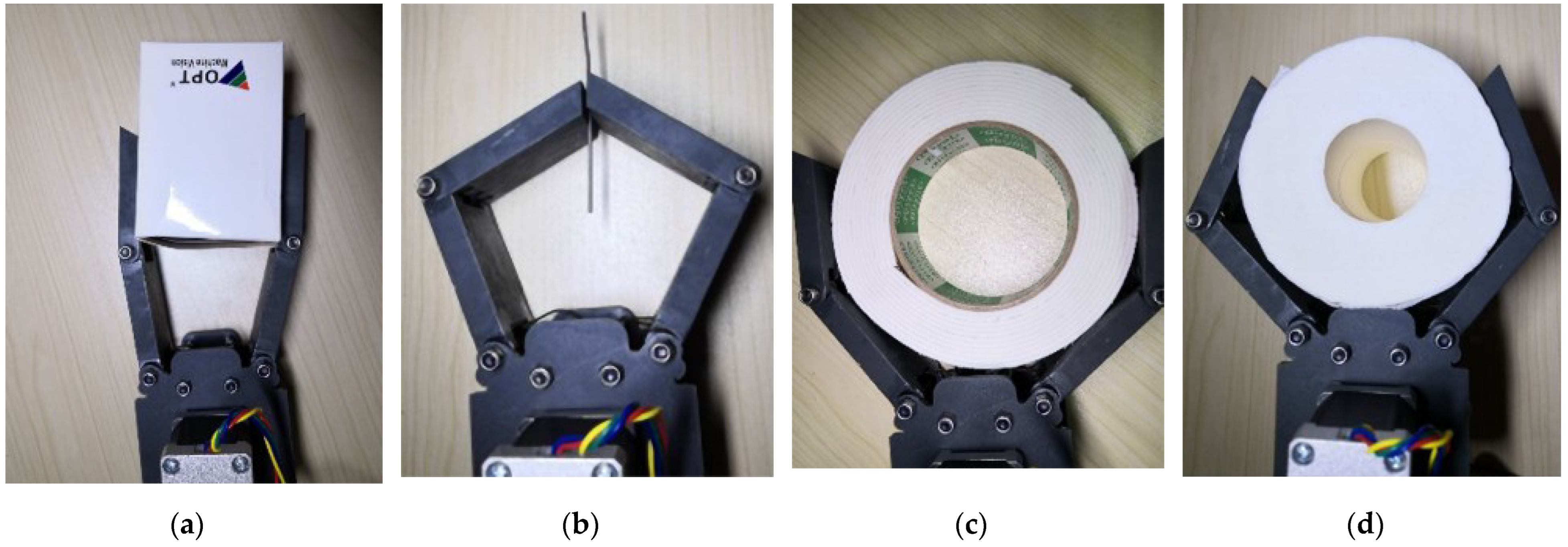
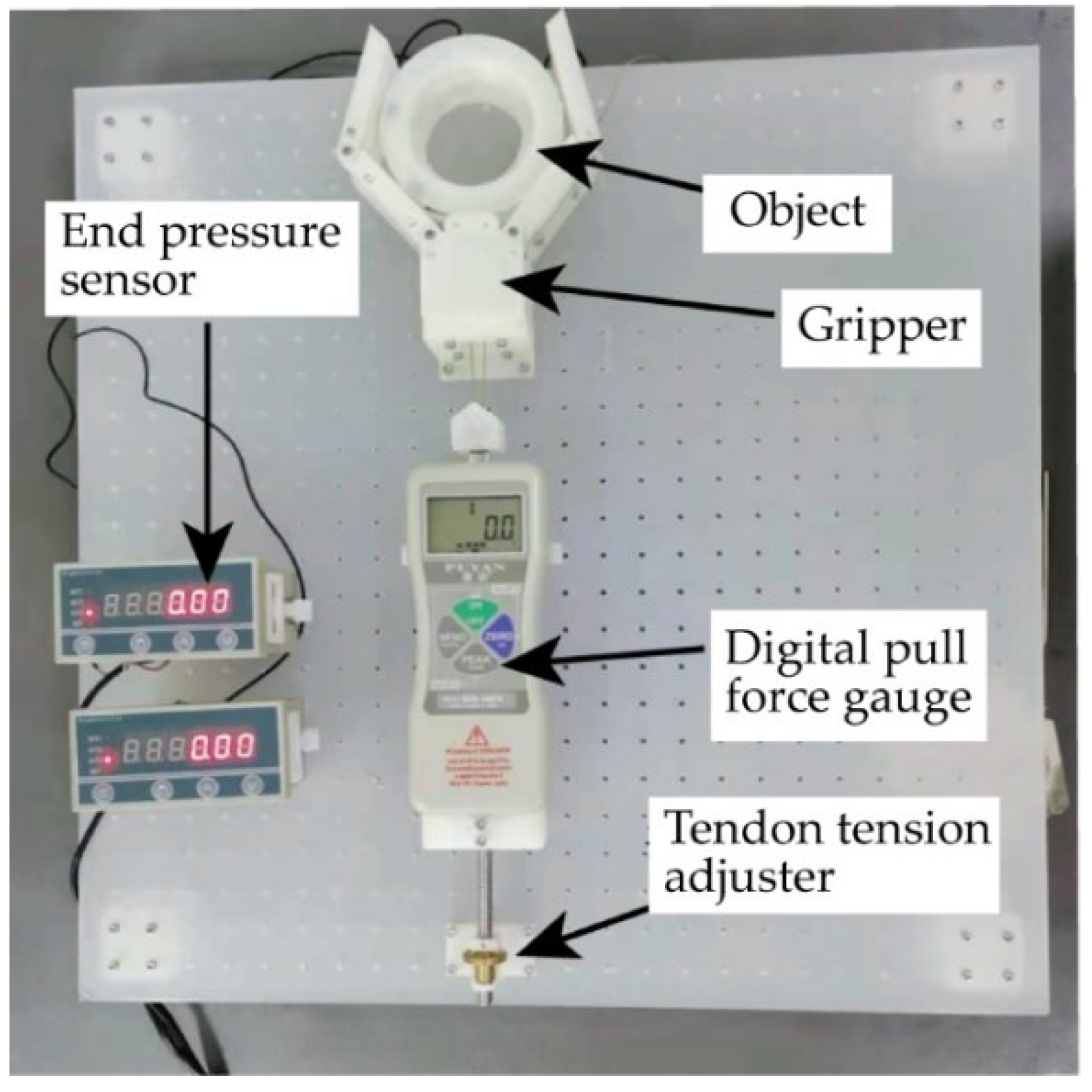
- We manufactured a prototype of the novel gripper and conducted some grasping experiments. The experimental result shows that four kinds of objects can be clamped tightly by the gripper proposed in this paper.
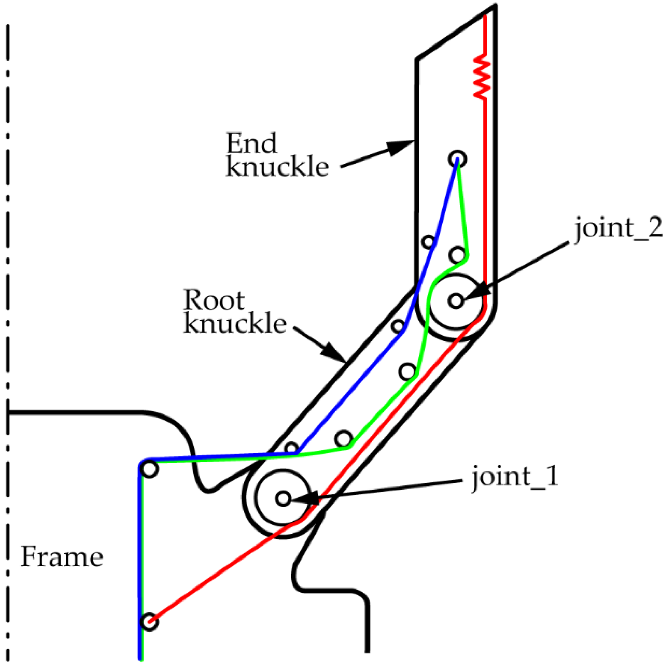
2. Gripper Structure Design
2.1. Calculate the Degrees of Freedom
2.2. Calculation of the Moment Acted on the Joint
2.3. Force Analysis of End Knuckle at joint_2
2.4. Movement Sequence Analysis
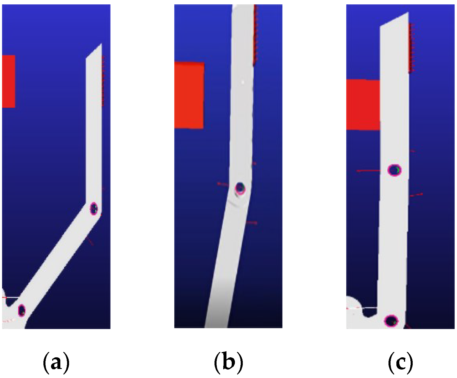
- If , the resultant moment acting on the end knuckle at joint_2 is counter clockwise. Under this condition, the movement sequence of two knuckles is: the end knuckle first rotates counterclockwise around joint_2, while the root knuckle remains stationary. When the end knuckle moves to the limit position, the relative position of the root knuckle and the end knuckle no longer changes. Then, the root knuckle and the end knuckle rotate counterclockwise around joint_1 synchronously to achieve the grasping of the object.
- If , the resultant moment acting on the end knuckle at joint_2 is clockwise. Under this condition, the movement sequence of two knuckles is: the root knuckle rotates counterclockwise around joint_1, while the end knuckle rotating clockwise around joint_2 simultaneously, so that the relative posture of the end knuckle to the frame remains constant. When the root knuckle is in contact with the object, the root knuckle stops rotating and the end knuckle rotates counterclockwise around joint_2 until the object is clamped.
2.5. Tendon Winding Path Design
3. Dynamic Simulation of Gripper
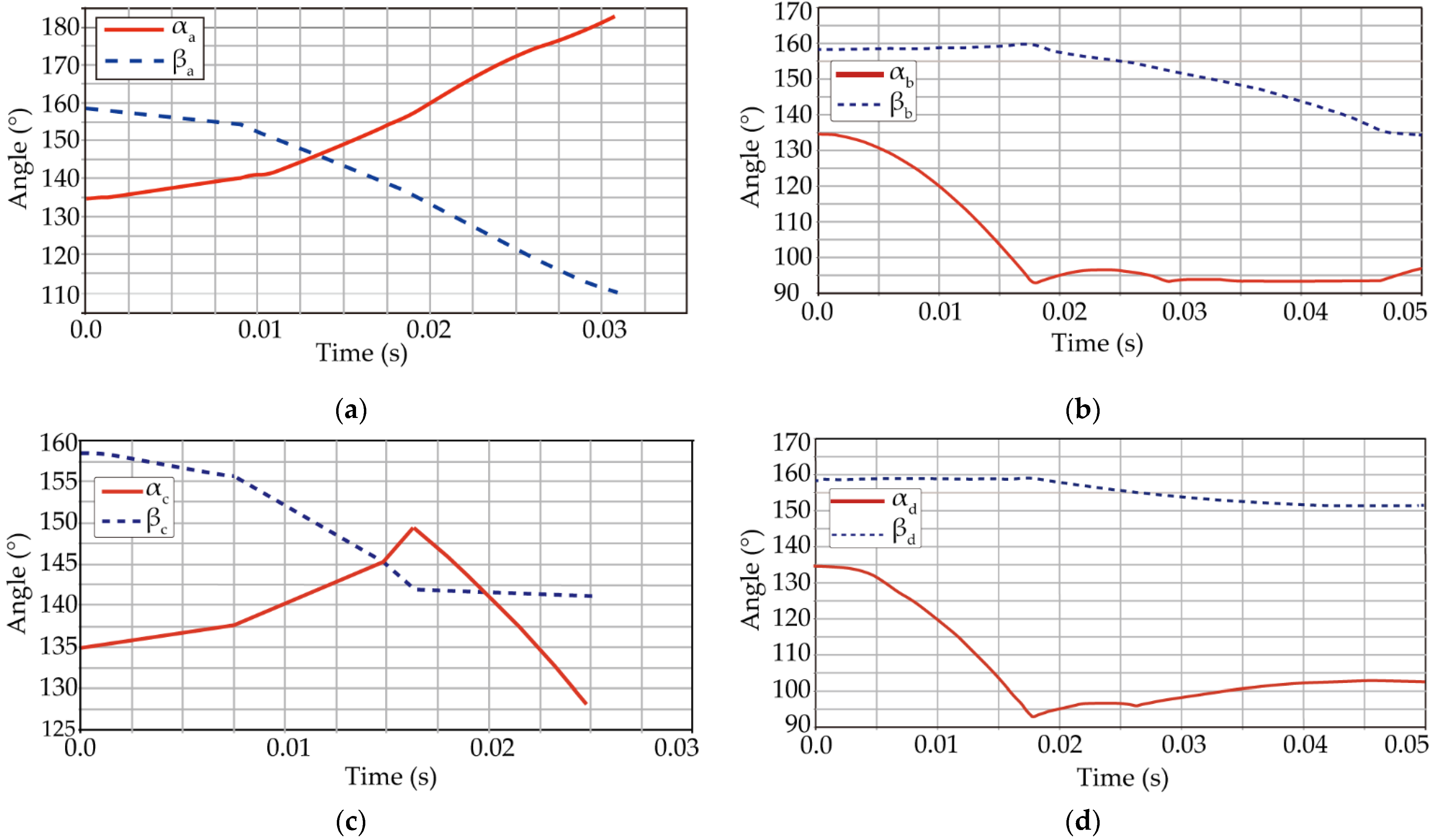
3.1. Movement Sequence Simulation
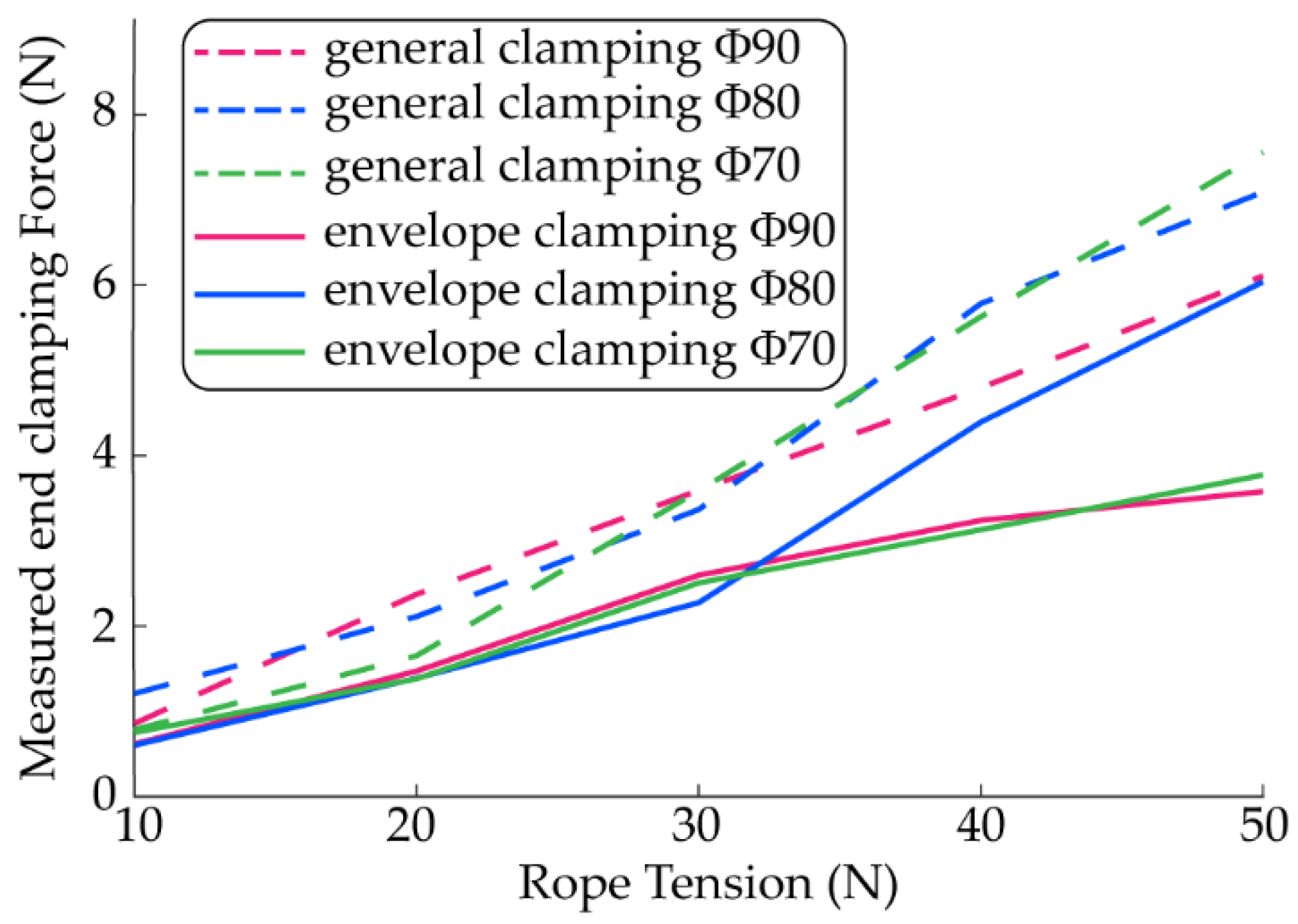
3.2. Simulation of End Clamping Force
4. Prototype Experimental Testing
4.1. Measurement of End Clamping Force
4.2. Test of Grasping Objects
5. Conclusions
- Although the resultant moment at the rotating joint of the end knuckle can be adjusted by switching the driving tendon, this kind of method is a little discrete; a more stepless adjusting method should be studied in the future.
- The end clamping force of a tendon-driven gripper can also be enlarged by optimising the geometric parameters of the gripper, such as the length and width of the knuckle, which is another area of research and has already been studied for some time.
- The end clamping force of a tendon-driven gripper is hardly influenced by the magnitude of a tendon tension; slight fluctuations in tendon tension may cause a sudden release by the gripper. Therefore, a kind of anti-loosen mechanism should be added to the gripper.
- The grasping operation of the gripper is not smooth enough, so it is necessary to improve the rotating joint structure of each knuckle to improve the clamping efficiency.
Author Contributions
Funding
Institutional Review Board Statement
Informed Consent Statement
Data Availability Statement
Conflicts of Interest
Appendix A

| Name | Meaning | Position |
|---|---|---|
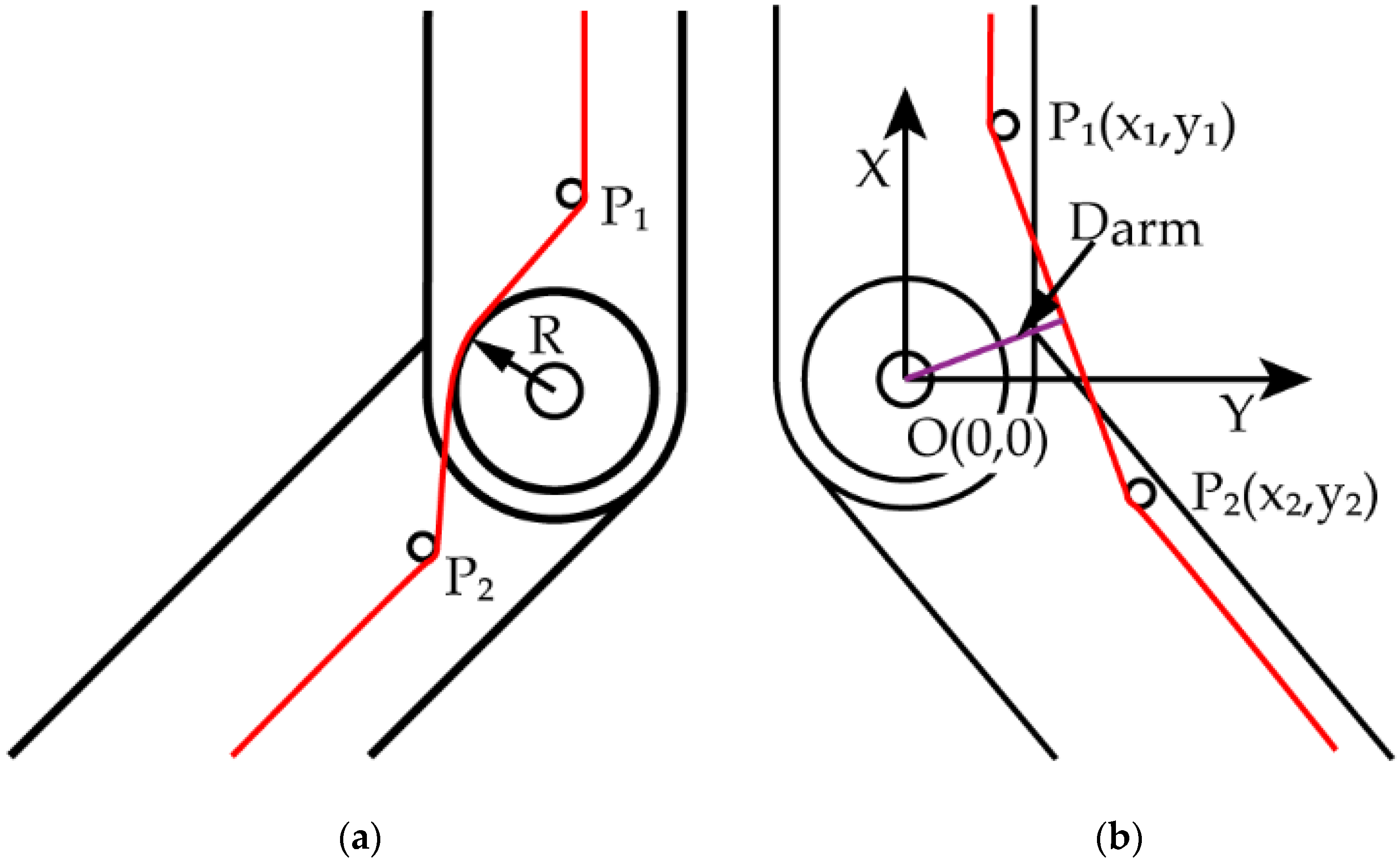
| R | The radius of guide wheel at the rotary joint of knuckle | Figure 2a |
| Darm | The moment arm of driving tendon tension at rotatory joint | Figure 2b |
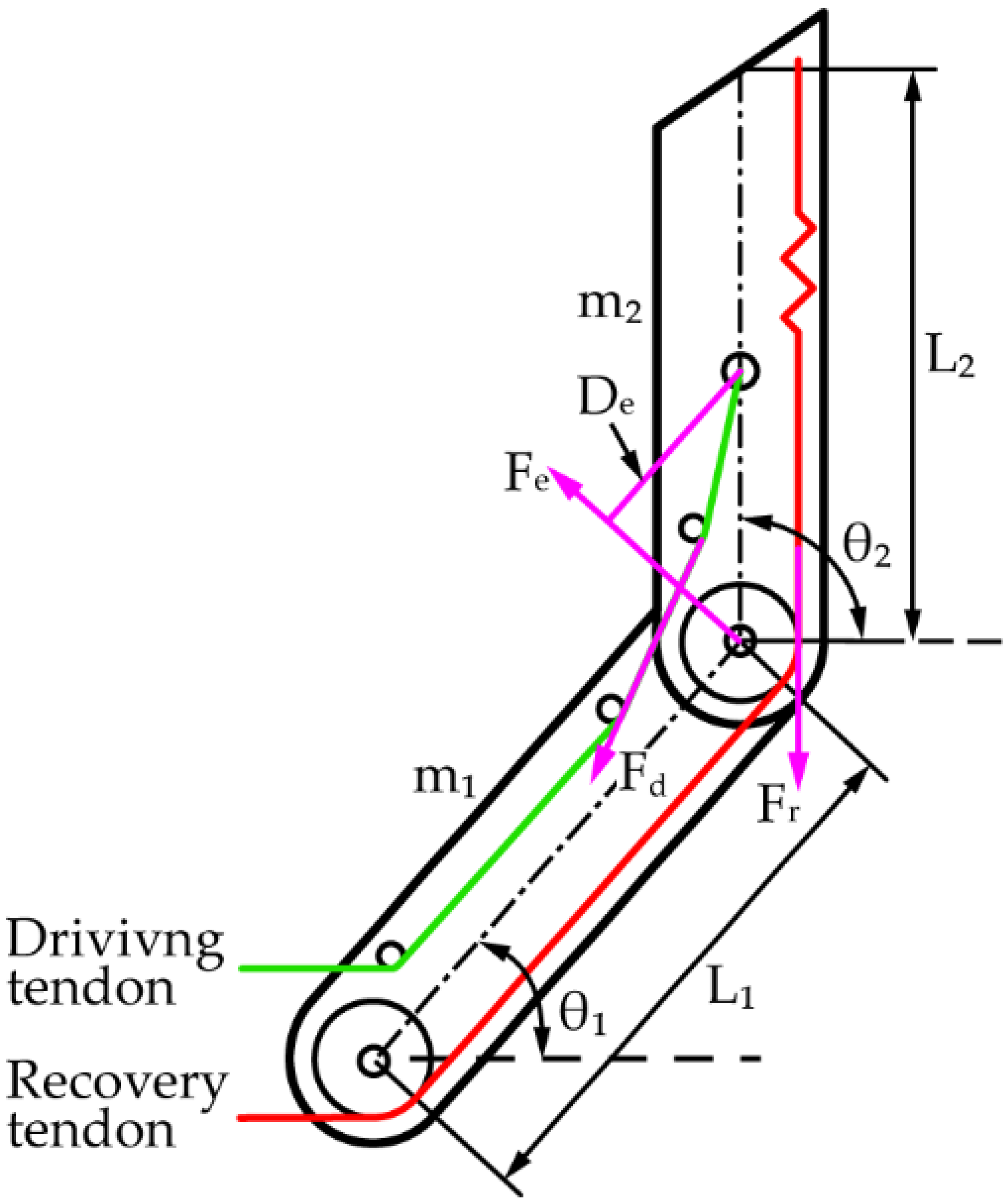
| m1(m2) | The mass of root knuckle (end knuckle) | Figure 3 |
| L1(L2) | The length of root knuckle (end knuckle) | Figure 3 |
| θ1(θ2) | The angle between the root (end) knuckle and the horizontal line | Figure 3 |
| Fd(Fr) | The tension of driving tendon (recovery tendon) | Figure 3 |
| Fe | The reaction force of root knuckle acting on the end knuckle | Figure 3 |
| Dd(Dr, De) | The moment arm of Fd (Fr, Fe) | Figure 3 |
| Td(Tr, Te) | The torque at joint_2 generated by Fd (Fr, Fe) | Section 2.4 |
| α | The angle between the centrelines of end knuckle and root knuckle | Section 3.1 |
| β | the obtuse angle between the root knuckle and the horizontal line | Section 3.1 |
| FoE | End Clamping Force of Envelope Clamping | |
| FoG | End Clamping Force of General Clamping |
References
- Agnieszka, R.; Arne, B.; Marcel, B.; Erik, S.M. The Smart Factory: Exploring Adaptive and Flexible Manufacturing Solution. Procedia. Eng. 2014, 69, 1184–1190. [Google Scholar]
- Laliberte, T.; Birglen, L.; Gosselin, C. Underactuation in robotic grasping hands. Jpn. J. Mach. Intell. Robot. Control. 2002, 4, 1–11. [Google Scholar]
- Nazma, E.; Suhaib, M. Tendon driven robotic hands: A review. Int. J. Mech. Eng. Robot. Res. 2012, 3, 350–357. [Google Scholar]
- Licheng, W.; Yanxuan, K.; Xiali, L. Review and Research Issues on Underactuated Finger Mechanism. In Proceedings of the 2015 Chinese Intelligent Automation Conference, Fuzhou, China, 8–10 May 2015. [Google Scholar]
- Vincent, B.; Clement, G. Mechanisms for Robotic Grasping and Manipulation. Annu. Rev. Control. Robot. Autom. Syst. 2021, 4, 573–593. [Google Scholar]
- Qinghua, L.; Junmeng, L.; Lufeng, L.; Yunzhi, Z.; Wenbo, Z. A supervised approach for automated surface defect detection in ceramic tile quality control. Adv. Eng. Inf. 2022, 53, 101692. [Google Scholar]
- Lufeng, L.; Wei, Y.; Zhengtong, N.; Jinhai, W.; Huiling, W.; Weilin, C.; Qinghua, L. In-field pose estimation of grape clusters with combined point cloud segmentation and geometric analysis. Comput. Electron. Agric. 2022, 200, 107197. [Google Scholar]
- Hirose, S.; Umetani, Y. The development of soft gripper for the versatile robot hand. Mech. Mach. Theory 1978, 13, 351–359. [Google Scholar] [CrossRef]
- Gosselin, C.; Pelletier, F.; Laliberte, T. An anthropomorphic underactuated robotic hand with 15 dofs and a single actuator. In Proceedings of the IEEE International Conference on Robotics and Automation, Pasadena, CA, USA, 19–23 May 2008. [Google Scholar]
- Odhner, L.U.; Jentoft, L.P.; Claffee, M.R.; Corson, N.; Tenzer, Y.; Ma, R.R.; Buehler, M.; Kohout, R.; Howe, R.D.; Dollar, A.M. A compliant, underactuated hand for robust manipulation. Int. J. Robot. Res. 2014, 33, 736–752. [Google Scholar] [CrossRef]
- Odhner, L.U.; Dollar, A.M. Dexterous manipulation with underactuated elastic hands. In Proceedings of the IEEE International Conference on Robotics and Automation, Shanghai, China, 9–13 May 2011. [Google Scholar]
- Aukes, D.M.; Kim, S.; Garcia, P.; Edsinger, A.; Cutkosky, M.R. Selectively compliant underactuated hand for mobile manipulation. In Proceedings of the IEEE International Conference on Robotics and Automation, St. Paul, MN, USA, 14–18 May 2012. [Google Scholar]
- Aukes, D.M.; Heyneman, B.; Ulmen, J.; Stuart, H.; Cutkosky, M.R.; Kim, S.; Garcia, P.; Edsinger, A. Design and testing of a selectively compliant underactuated hand. Int. J. Robot. Res. 2014, 33, 721–735. [Google Scholar] [CrossRef]
- Ciocarlie, M.; Hicks, F.M.; Stanford, S. Kinetic and dimensional optimization for a tendon-driven gripper. In Proceedings of the 2013 IEEE International Conference on Robotics and Automation, Karlsruhe, Germany, 6–10 May 2013. [Google Scholar]
- Ciocarlie, M.; Hicks, F.M.; Holmberg, R.; Hawke, J.; Schlicht, M.; Gee, J.; Stanford, S.; Bahadur, R. The Velo gripper: A versatile single-actuator design for envelopeing, parallel and fingertip grasps. Int. J. Robot. Res. 2014, 33, 753–767. [Google Scholar] [CrossRef]
- Firouzeh, A.; Paik, J. Grasp mode and compliance control of an under-actuated origami gripper using adjustable stiffness joints. IEEE-Asme Trans. Mechatron. 2017, 22, 2165–2173. [Google Scholar] [CrossRef]
- Firouzeh, A.; Salehian, S.S.M.; Billard, A.; Paik, J. An under actuated robotic arm with adjustable stiffness shape memory polymer joints. In Proceedings of the IEEE International Conference on Robotics and Automation, Seattle, WA, USA, 26–30 May 2015. [Google Scholar]
- Palli, G.; Melchiorri, C. Friction compensation techniques for tendon-driven robotic hands. Mechatronics 2014, 24, 108–117. [Google Scholar] [CrossRef]
- Dong, H.; Asadi, E.; Qiu, C.; Dai, J.; Chen, I.-M. Grasp analysis and optimal design of robotic fingertip for two tendon-driven fingers. Mech. Mach. Theory 2018, 130, 447–462. [Google Scholar] [CrossRef]
- Dong, H.; Asadi, E.; Qiu, C.; Dai, J.; Chen, I.-M. Geometric design optimization of an under-actuated tendon-driven robotic gripper. Robot. Comput. Manuf. 2018, 50, 80–89. [Google Scholar] [CrossRef]
- Ma, T.; Yang, D.; Zhao, H.; Ai, N. Grasp analysis and aptimal design of a new underactuated manipulator. Chin. J. Robot. 2020, 42, 354–364. [Google Scholar]
- Bao, J.; Han, K.; Zheng, C.; Cao, Y.; Sun, K. Design of underactuated manipulator based on metamorphic theory. Chin. J. Mech. Drive 2020, 44, 90–93. [Google Scholar]
- Li, X.; Guo, J.; Sun, W.; Shang, D.; Wen, B. Design and Contact Force Analysis of Under-actuated Manipulator with Hybrid Working Mode. Chin. J. Mech.-Eng. 2021, 57, 8–18. [Google Scholar]
- Schee, J.Y.; Minsik, C.; Bomin, J.; Yong, L.P. Elongatable Gripper Fingers With Integrated Stretchable Tactile Sensors for Underactuated Grasping and Dexterous Manipulation. IEEE Trans. Robot. 2022, 38, 2179–2193. [Google Scholar]


| Equipment | Type |
|---|---|
| End pressure sensor | (DYHW-108, DAYSEN-SOR, China) |
| Digital pull force gauge | (DS2-500N, PUYAN, China) |
| Driving motor | (42BYG34-401A, China) |
| Object Size | Tendon Tension (N) | FoE (N) | FoG (N) | Increase |
|---|---|---|---|---|
| Φ70 | 10 | 0.76 ± 0.05 | 0.85 ± 0.07 | 11.8% |
| 20 | 1.38 ± 0.21 | 1.57 ± 0.13 | 13.8% | |
| 30 | 2.51 ± 0.17 | 3.26 ± 0.46 | 29.9% | |
| 40 | 3.13 ± 0.25 | 5.68 ± 0.74 | 81.5% | |
| 50 | 3.77 ± 0.41 | 7.44 ± 0.98 | 97.3% | |
| Φ80 | 10 | 0.60 ± 0.04 | 1.21 ± 0.13 | 101.7% |
| 20 | 1.38 ± 0.16 | 2.13 ± 0.18 | 54.3% | |
| 30 | 2.51 ± 0.32 | 3.38 ± 0.27 | 34.7% | |
| 40 | 3.14 ± 0.25 | 5.78 ± 0.81 | 84.1% | |
| 50 | 3.76 ± 0.41 | 7.09 ± 0.89 | 88.6% | |
| Φ90 | 10 | 0.61 ± 0.09 | 0.86 ± 0.09 | 41.0% |
| 20 | 1.47 ± 0.12 | 2.37 ± 0.21 | 61.2% | |
| 30 | 2.59 ± 0.19 | 3.59 ± 0.47 | 38.6% | |
| 40 | 3.25 ± 0.49 | 4.80 ± 0.43 | 47.7% | |
| 50 | 3.58 ± 0.27 | 6.11 ± 0.86 | 70.7% |
Publisher’s Note: MDPI stays neutral with regard to jurisdictional claims in published maps and institutional affiliations. |
© 2022 by the authors. Licensee MDPI, Basel, Switzerland. This article is an open access article distributed under the terms and conditions of the Creative Commons Attribution (CC BY) license (https://creativecommons.org/licenses/by/4.0/).
Share and Cite
Zhang, Y.; Xia, D.; Lu, Q.; Zhang, Q.; Wei, H.; Chen, W. Design, Analysis and Experimental Research of Dual-Tendon-Driven Underactuated Gripper. Machines 2022, 10, 761. https://doi.org/10.3390/machines10090761
Zhang Y, Xia D, Lu Q, Zhang Q, Wei H, Chen W. Design, Analysis and Experimental Research of Dual-Tendon-Driven Underactuated Gripper. Machines. 2022; 10(9):761. https://doi.org/10.3390/machines10090761
Chicago/Turabian StyleZhang, Yunzhi, Dingkun Xia, Qinghua Lu, Qinghua Zhang, Huiling Wei, and Weilin Chen. 2022. "Design, Analysis and Experimental Research of Dual-Tendon-Driven Underactuated Gripper" Machines 10, no. 9: 761. https://doi.org/10.3390/machines10090761
APA StyleZhang, Y., Xia, D., Lu, Q., Zhang, Q., Wei, H., & Chen, W. (2022). Design, Analysis and Experimental Research of Dual-Tendon-Driven Underactuated Gripper. Machines, 10(9), 761. https://doi.org/10.3390/machines10090761