Article

Wear Mechanisms and Performance of PET Shredder Blade with Various Geometries and Orientations

by
Jin Hoong Wong
1,
Wong Min Jin Karen
1,
Saffuan Awg Bahrin
2,
Bih Lii Chua
1,
Gan Jet Hong Melvin
3,* and
Nancy Julius Siambun
3,*
1
Faculty of Engineering, Universiti Malaysia Sabah, Jalan UMS, Kota Kinabalu 88400, Sabah, Malaysia
2
Mechanical Engineering Department, Politeknik Kota Kinabalu, Jalan Politeknik, Kota Kinabalu Industrial Park, Kota Kinabalu 88460, Sabah, Malaysia
3
Centre of Research in Energy and Advanced Materials, Faculty of Engineering, Universiti Malaysia Sabah, Jalan UMS, Kota Kinabalu 88400, Sabah, Malaysia
*
Authors to whom correspondence should be addressed.
Machines 2022, 10(9), 760; https://doi.org/10.3390/machines10090760
Submission received: 29 July 2022 / Revised: 30 August 2022 / Accepted: 30 August 2022 / Published: 2 September 2022
(This article belongs to the Section Advanced Manufacturing)

Abstract

:
Shredder blade is the main component of a shredder machine used in plastic recycling. A comparative performance study was conducted on the shredder blade with different geometries and orientations to understand its wear and shredding mechanism. Identification of the loading distribution along the shredder blades was observed in different orientations. The microstructure and hardness of the worn cutting edge and as-received shredder blade were characterised by optical microscopy, scanning electron microscopy along with the energy dispersive X-ray, X-ray diffraction analysis and hardness testing. The wear mechanism in the shredder blades was categorised as progressive wear. The progressive wear was due to the abrasive, adhesive, and oxidation wear. Recycling efficiency, shredding efficiency, and percentage retention are the parameters used to evaluate the performance of the machine with various geometries and orientations. The best combination of the geometry and orientation is the double-edge shredder blade with spiral orientation, which exhibited recycling efficiency at 97.39 ± 0.04%, shredding efficiency at 69.53 ± 1.32%, and retention at 2.61 ± 0.04%, along with a smaller number of blades recorded severe wear.

1. Introduction

Production of plastics has been increasing globally due to its burgeoning applications, including food and beverage packaging, textile, automotive, and manufacturing, along with medical devices such as surgical equipment, drips, and blister packs for pills [1,2,3]. The increasing use of plastics has caused land and water pollution [4]; hence, it requires adequate attention to solve the plastic waste management and disposal processes [4,5].
Several intricate processes are involved in plastic recycling prior to the further processing step into a new product, such as sorting, crushing, shredding, and washing. Commonly, the plastic recycling process is carried out through centralised networks [6], which leads to a low recycling rate due to the challenge in the collection, separation, and sorting processes together with the transportation of the plastic waste that requires significant capital and extensive operating investment [7,8,9]. Therefore, a shredder machine was proposed at the recycling centre as the primary machine for the recycling process [10]. The shredder machine was utilised to shred the waste plastic into tiny sizes for a further recycling process.
The shredder machine mainly consisted of four fundamental components: (i) a shaft and set of blades, (ii) a motor, gears, bearing, and transmission, (iii) a hopper, and (iv) a framework. The most complicated consideration is the geometry and orientations of the blades, which directly influence the efficiency [10]. The shredding action occurs when the single shaft rotates, and the plastic workpieces are shredded by the rotating and fixed shredder blades. Examples of plastic workpieces are Polyethylene Terephthalate (PET), High-Density Polyethylene (HDPE), Polyvinyl Chloride (PVC), Low-Density Polyethylene (LDPE), Polypropylene (PP) and Polystyrene (PS).
The number of cutting edges changes the point of contact during shredding and the loading distribution along the shredder blades, thus affecting machine performance [11]. Rathnam et al. [12] compared double and sextuple-edge shredder blades and discovered that the greater number of edges reduced the shredding performance and increased the risk of workpieces skipping and winding up on the shredder blade [12]. Similar occurrences were observed by Ekman [13] and Ravi [14], where the greater number of cutting edges does not improve the shredding performance. Meanwhile, VijayAnanth et al. [15] utilised a triple-edge blade in a double-shafted shredding machine and reported their machine works well and can shred plastics [15].
During the shredding operation, the shredder blade generally directs the workpieces to be shredded between two sets of blades arranged along with two parallel axles. Shredding occurs at the intersection of the two opposing sets of blades that are interlaced with overlapping radii of the opposite axes [16]. Several orientations, such as spiral [14], zigzag [17], series [18], and V-orientation [13], were utilised on the shredder blades for the shredding process. Various blade geometries and orientations in the shaft might constrain the efficiency of the shredding, which creates inconsistent load distribution, resulting in certain sections of the blades experiencing higher load compared to the others [19].
The shredding process primarily involved a dry impact/sliding, which induced a shear deformation on the workpieces, such as PET. It may cause severe wear on the shredder blades, especially at the sharp cutting edges [20,21,22]. Consequently, the shredder blades required regular maintenance due to wear and tear during the shredding process. Thus, a precise design of the shredder blade geometry was vital in controlling and improving the wear resistance during the shredding processes [21]. This has driven the demand for further studies into the wear behaviour of shredder blades in various geometries and blades’ orientations during the shredding process (e.g., sliding wear and impact wear) [23,24].
Although several investigations on the shredding performance have been conducted, fewer studies have been performed for the analysis of the wear behaviour of the shredder blades [10,19,25]. Due to the wear conditions between the blades and PET plastic during the shredding process being complicated to observe and quantify, it is challenging to estimate the wear mechanisms of the blades from the laboratory scale simulations [5,23,24].
Therefore, the purpose of this study is to investigate the wear mechanism of shredder blade cutting edges with different geometries and orientations, respectively, and the blade’s performance. Evaluation of the performance of the shredder machine was according to the recycling efficiency, shredding efficiency, and percentage retention.

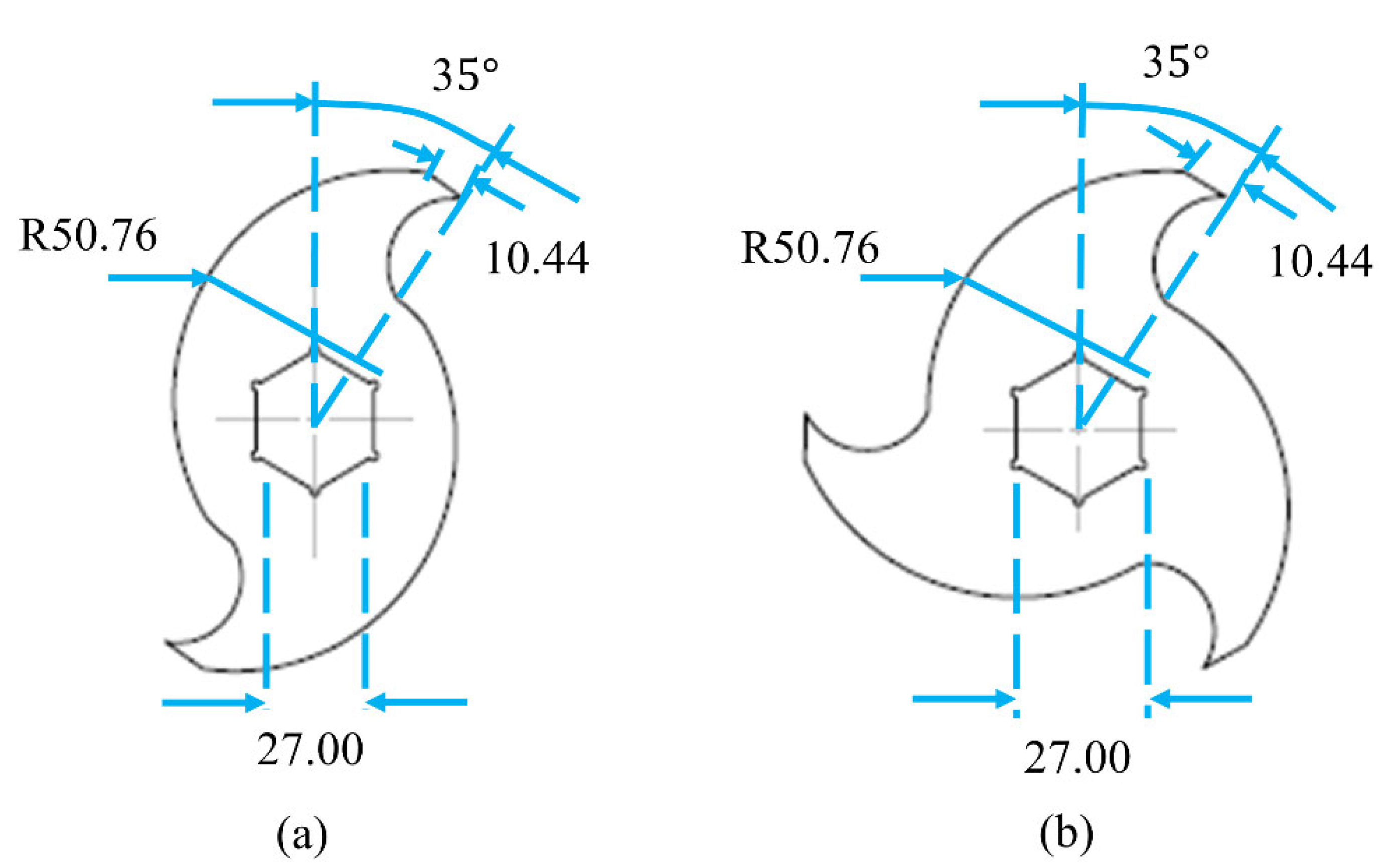
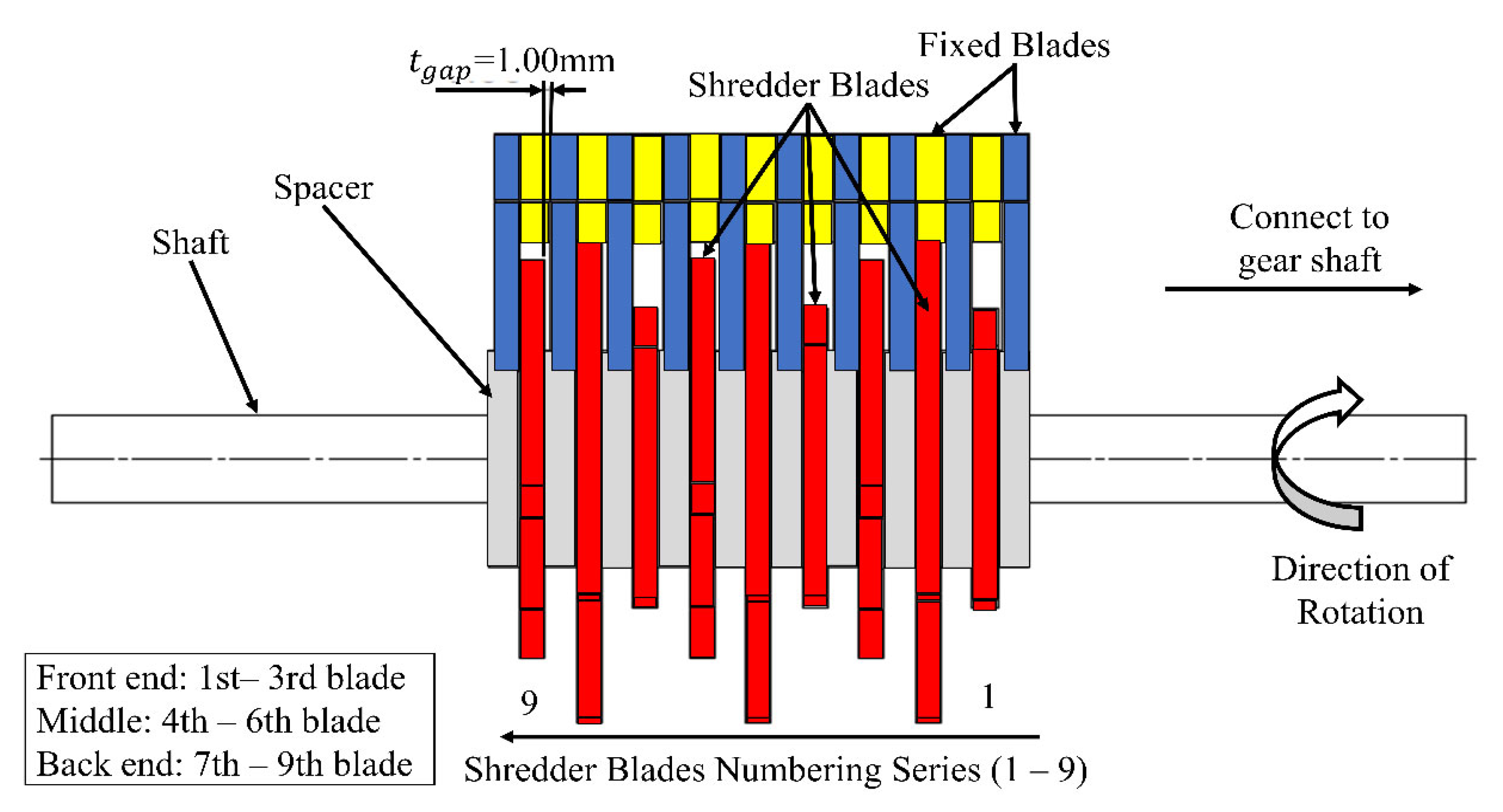
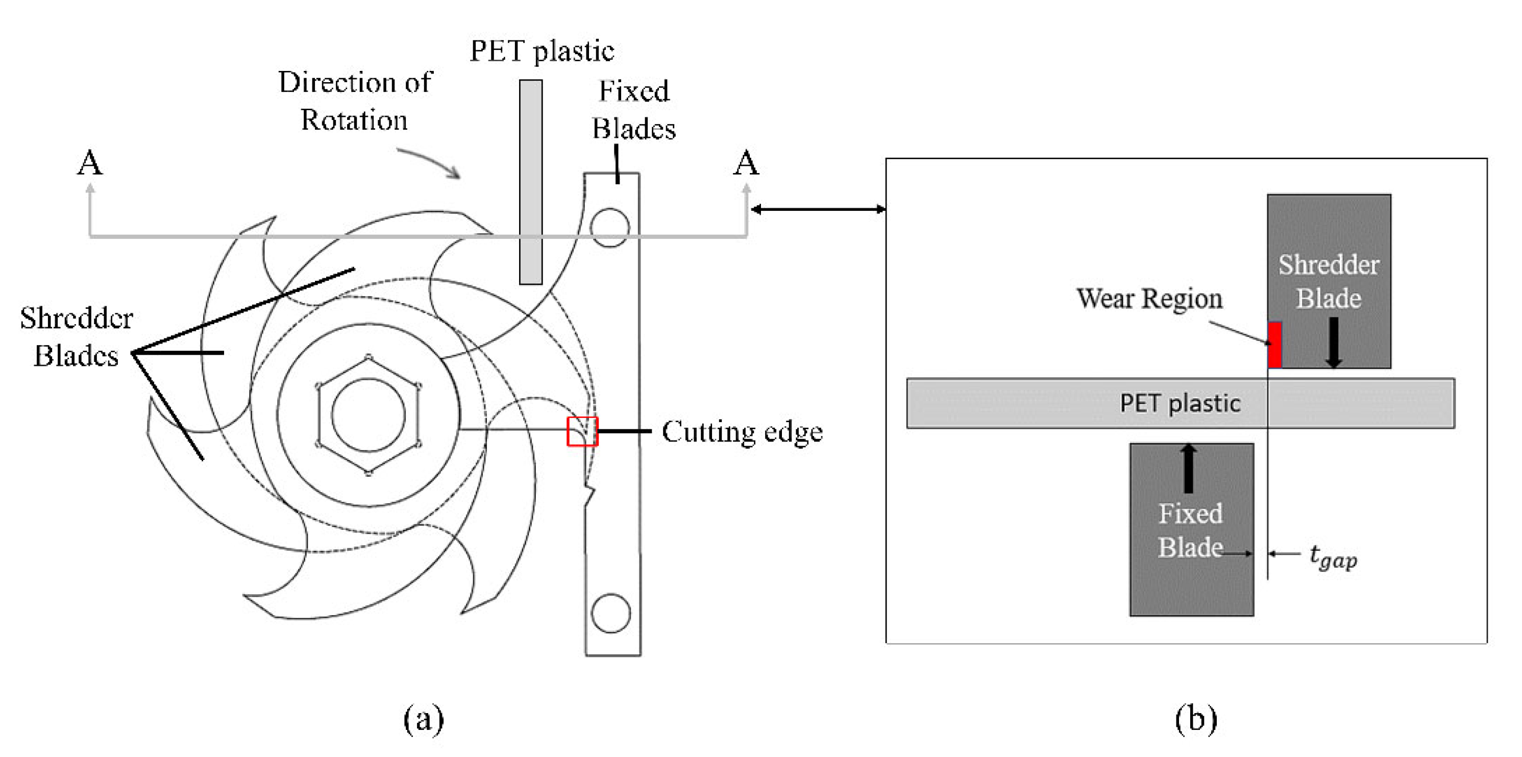
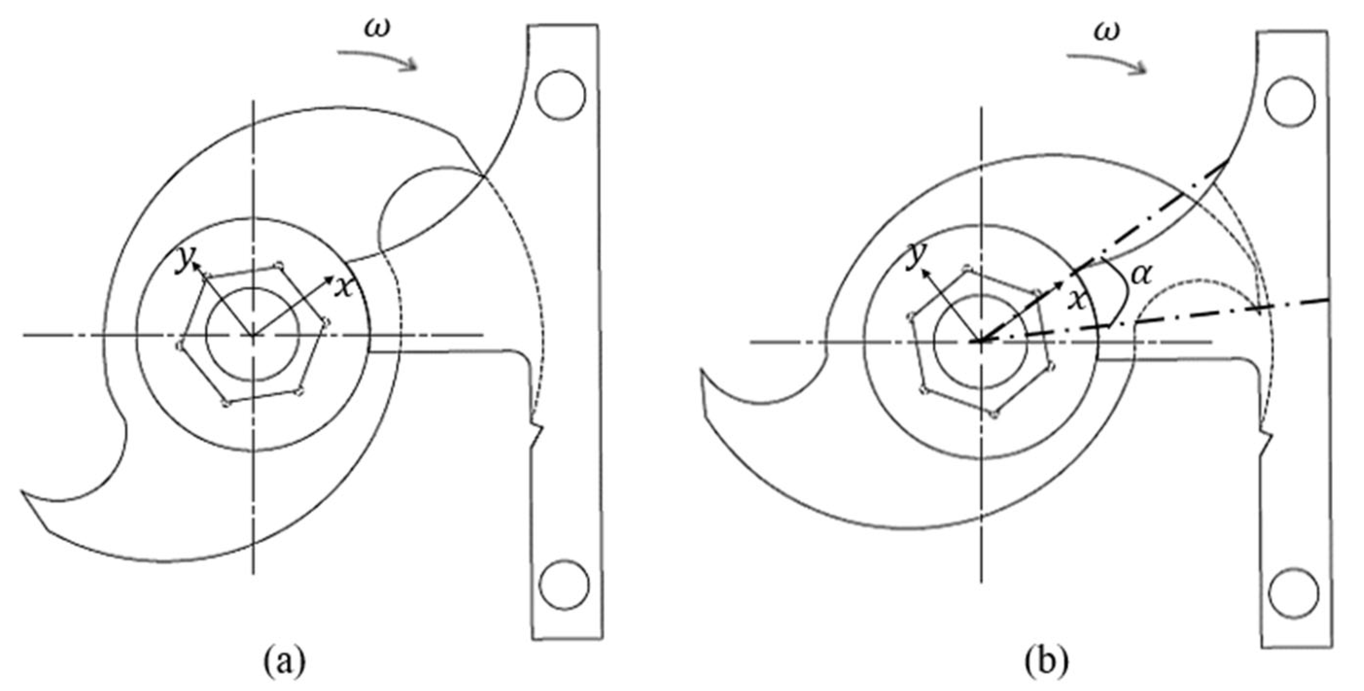
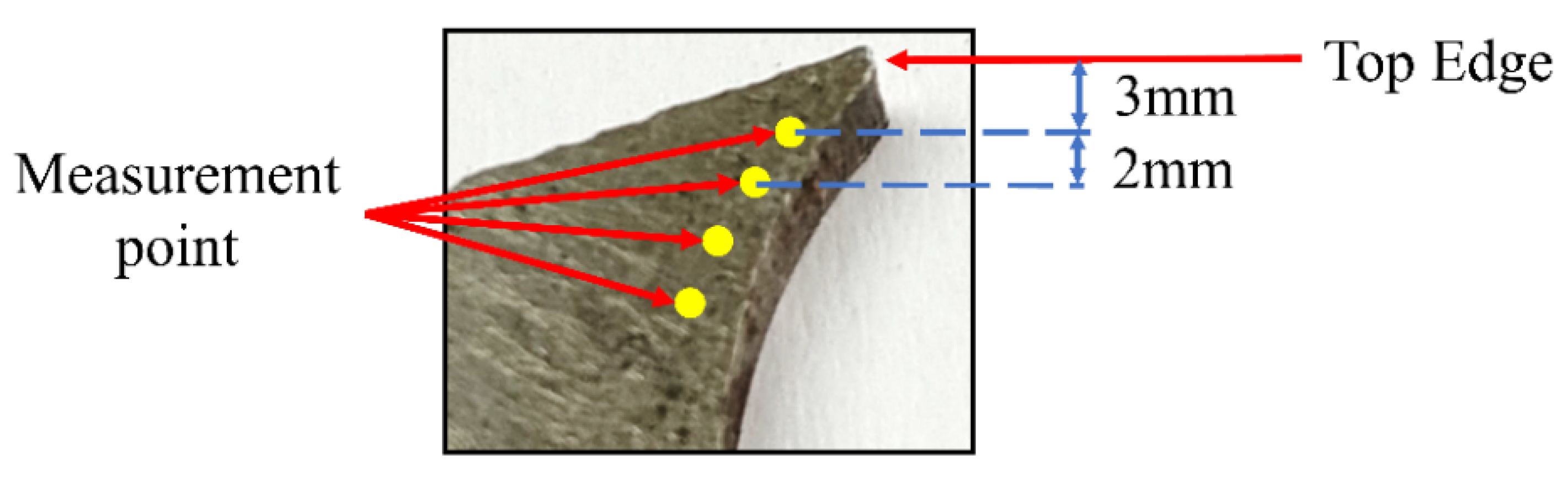
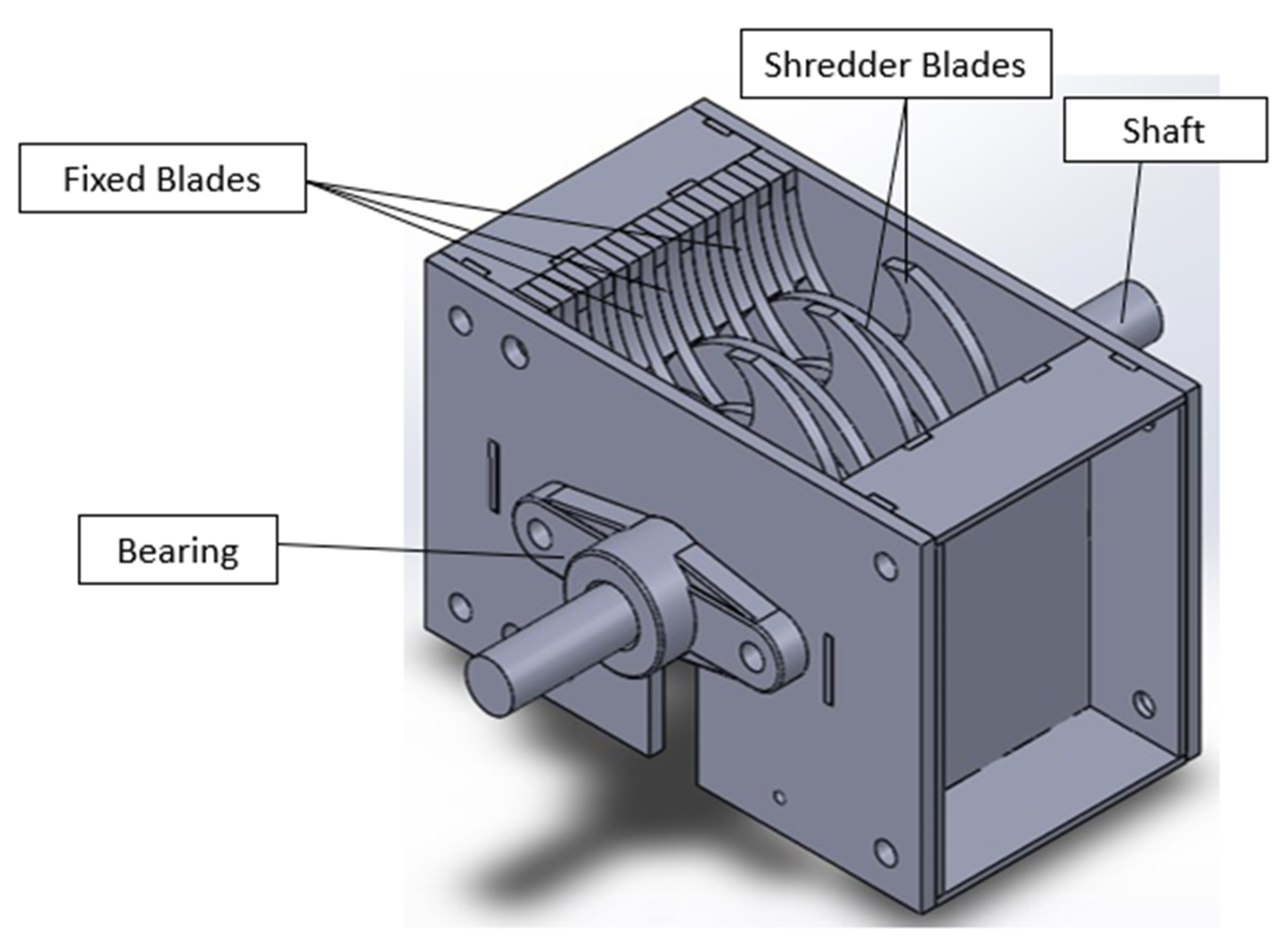
2. Experimental Section

A small-scale shredding machine for PET plastic was fabricated, and a performance test was conducted using a 3 hp single phase electric motor (rotational speed at 2800 rpm) as the prime mover. The motor was connected to a 1:60 ratio gearbox to reduce the rotational speed (about 47 rpm) and increase the torque of the rotating shaft to improve the shredding force of the shredder blades. The utilised geometrical design in this study, double-edge and triple-edge blades, is shown in Figure 1a and Figure 1b, respectively.
Design of the small-scale shredder machine was adopted from Precious Plastic Group [26]. The single-shaft plastic shredder was invented by Dave Hakkens, and the design is available on the Precious Plastic website [19,26]. In small-scale shredder machines, there are several geometries of shredder blades, including double-edge [12,19,27] and triple-edge shredder blades [15,28]. In this study, the shredder blade design was adjusted to certain detail, i.e., the cutting angle was fixed at 35°, and the cutting edge length was fixed at 10.44 mm for both double and triple-edge shredder blades to suit the shredder machine. The fabricated double-edge and triple-edge blades were mounted to a hexagonal shaft in spiral and V-orientation before the blades were installed in the shredder machine. Figure 2 illustrates the orientations of the double-edge and triple-edge blades. The abbreviations of the shredder blades in different geometries and orientations are summarised in Table 1.
The shredder machine was assembled by welding the parts together while the detachable parts were bolted. Figure 3 depicts the schematic diagram of the small-scale plastic shredder machine with throughput of approximately 10 kg/h. The throughput of a shredder machine is defined as the ratio of output mass of shredded workpieces to the time taken for the shredding process
Figure 4 illustrates the configuration of the shredder blades in the shredder machine, where the shaft consisted of 10 removable spacers and 9 shredder blades made of low carbon steel or mild steel. Low carbon steel or mild steel generally comprises 0.05 wt.% to 0.25 wt.% of carbon, where its hardness is between 10 HRC to 34 HRC [29,30]. Hence the as-received low carbon steel was tested for its hardness using Rockwell Hardness Tester, and the hardness was measured at 17 HRC. Typically chemical composition of low carbon steel is C: 0.16 wt.%, Si: 0.40 wt.%, Mn: 0.70 wt.%, S: 0.03 wt.%, P: 0.03 wt.% and Fe: 98.68 wt.%, and our recorded hardness correspond accordingly [31,32,33]. Based on the finding from Ravi et al. [14] and Nasr et al. [28], low carbon steel is the most suitable material in the fabrication of the shredder blades for plastic shredder machines because it is available at minimal cost, and ease of welding due to its specific properties. Low carbon steel is unresponsive to heat treatments intended to form martensite, relatively soft and weak but has outstanding ductility and toughness; in addition, they are machinable [34]. Thus, in this study, low-carbon steel was utilised as the shredder blade and fixed blade material.
The numbering series of the shredder blades starts from the shaft end that is connected to the gear shaft. The gap between one side of the rotating shredder blades and the fixed blades, t g a p , was fixed at 1.00 mm. The gap was implemented in order to prevent the shredded workpieces from becoming stuck during the shredding process, as well as to obtain a specific size of the workpiece pellets after it was shredded [10,35,36]. The gap provides a slight shift in the shredder blade and the loading concentration of PET during the shredding process. Whilst the other surface of the shredder blades is in contact with the subsequently fixed blade to avoid misalignment during the shredding process. However, the shredder blades are not necessarily always in contact with the fixed blades since the gap at one side provides a slight shift of the shredder blades during the shredding process.
Figure 5 illustrates the side view of the shredder blades, fixed blades, and the cross-section of the PET plastic, along with the cross-section of A-A, which depicts two tool blades and the gap, t g a p .
According to Figure 5a, the shredding action was generated from the narrow gap, t g a p , between the shredder blade and fixed blade. Based on Figure 5b, the wear region of the shredder blades was at the edge of the blades where it occurred, adjacent to the gap between the shredder blades and fixed blades. Thus, the wear performance of the shredder blade was focused on the cutting edge of the shredder blade. PET plastic was selected as the workpiece. It was cut to a rectangular shape with dimensions of around 90 mm length × 40 mm width and fed into the shredder machine. The workpiece length was approximately the same as the length of blades 1 to 9 along the shredding shaft to ensure the workpiece was uniformly fed to the shredder blades. The workpiece was gradually fed into the shredding chamber during the shredding process. Determination of the loading distribution of each shredder blade for different orientations was based on the wear rate of each blade.
Two adjacent shredder and fixed blades are used as a set to shred PET plastic. Figure 6 shows the front view of the arrangement of the shredder and fixed blades. The shredder blades rotate at a mean angular speed, ω , of 47 rpm. An offset angle, α , is used to specify the relative orientation of the shredder and fixed blades. The offset angle α , as shown in Figure 6b, is defined as the angle that shredder blade rotates from the α = 0 position in Figure 6a. The change in offset angle will alter the wear pattern on the worn cutting edges of shredder blade, as will be demonstrated in the following analysis.
The wear mechanism of the double-edge and triple-edge blades in different orientations was investigated based on the blade’s material wear rate. The wear rate was defined as the volume loss (mm3), where the volume loss was achieved by the mass loss divided by the density of the low-carbon steel. The density of the low-carbon steel used in this experiment is 7850 kg/m3. The shredder blade’s wear was initially compared between same geometry with different orientations, followed by the wear effect on different blade geometries. Mass of the blades was weighed before and after the shredding process using an analytical balance with precision of 0.001 g (Ohaus Pioneer PA413C, Ohaus Corp., Parsippany, NJ, USA, 410 g). The microstructure of the worn cutting edge of the shredder blades was examined under optical microscopic (5× magnification) (Olympus BX60M, Olympus, Tokyo, Japan) and scanning electron microscopic (SEM, Hitachi S3400N, Hitachi, Tokyo, Japan) along with the elemental composition by energy dispersive X-ray (EDX, QUANTEX Esprit 1.9) microanalysis before and after shredding about 1.25 kg of PET plastic. Crystalline structure of the worn cutting edge was observed using the X-ray diffractometer (XRD, Rigaku SmartLab) with Cu Kα radiation, λ = 1.5406 Å and operating at 40 kV and 50 mA.
The hardness properties of the shredder blades were measured using Rockwell hardness scale C with 150 kg load (Mitutoyo ATK F-1000, Mitutoyo, Kawasaki, Japan). XRD and hardness analysis were carried out on the fourth blade (DS4, TS4, DV4 and TV4) for all geometries and orientations and compared with the as-received shredder blades (P). The measurement point of the hardness is displayed in Figure 7. The first measurement was taken 3 mm from the top edge, and the following measurement points were taken at 2 mm intervals. The hardness at the edge of the as-received shredder blades (P) was found at average of 17HRC.
The cutting edges of each as-received shredder blade were ground to obtain similar initial wear before the shredding process. Furthermore, the running-in time wear phase [37] involves the time-dependent and scale-dependent. In this study, the scale of crushed material was set to 1.25 kg, where the time of the shredding process was not mainly considered. Small amount of workpiece load was utilised in this experiment as the working load range 1.2 kg–2.5 kg of workpieces is suitable with the machine throughput of 15 to 75 kg/h [5,25,27]. Various approaches have been reported to determine the shredder machine’s performance, including recycling efficiency, retention, and shredding efficiency [5,10,25]. Performance of the shredder machine was determined by the recycling efficiency (RE), which is the ratio of the output mass of the recycled PET plastic (Q) to the input mass of PET plastic (I), as shown in Equation (1). The retained mass (R), also known as the PET plastic that was left uncut in the shredder machine, was shown in Equation (2). In fact, low R value indicates good shredding process. Percentage of retention was determined using Equation (3) [5,10,25]. The shredding efficiency is the measure of the percentage of recyclable shredded PET plastic, with area size less than or equal to 1 cm × 1 cm (Ms1), relative to the total shredded PET plastic (Q) shown in Equation (4) [5,38]. A screen/mesh was used to filter and control the shredded PET plastic size.
R e c y c l i n g   E f f i c i e n c y   ( R E ) = O u t p u t   m a s s   o f   r e c y c l e d   w a s t e   P E T   p l a s t i c   ( Q ) I n p u t   m a s s   o f   w a s t e   P E T   p l a s t i c   ( I ) × 100 %
R = I Q
R e t e n t i o n   ( % ) = R I × 100 %
S h r e d d i n g   E f f i c i e n c y   ( S E ) = M s 1 Q × 100 %

3. Results and Discussion

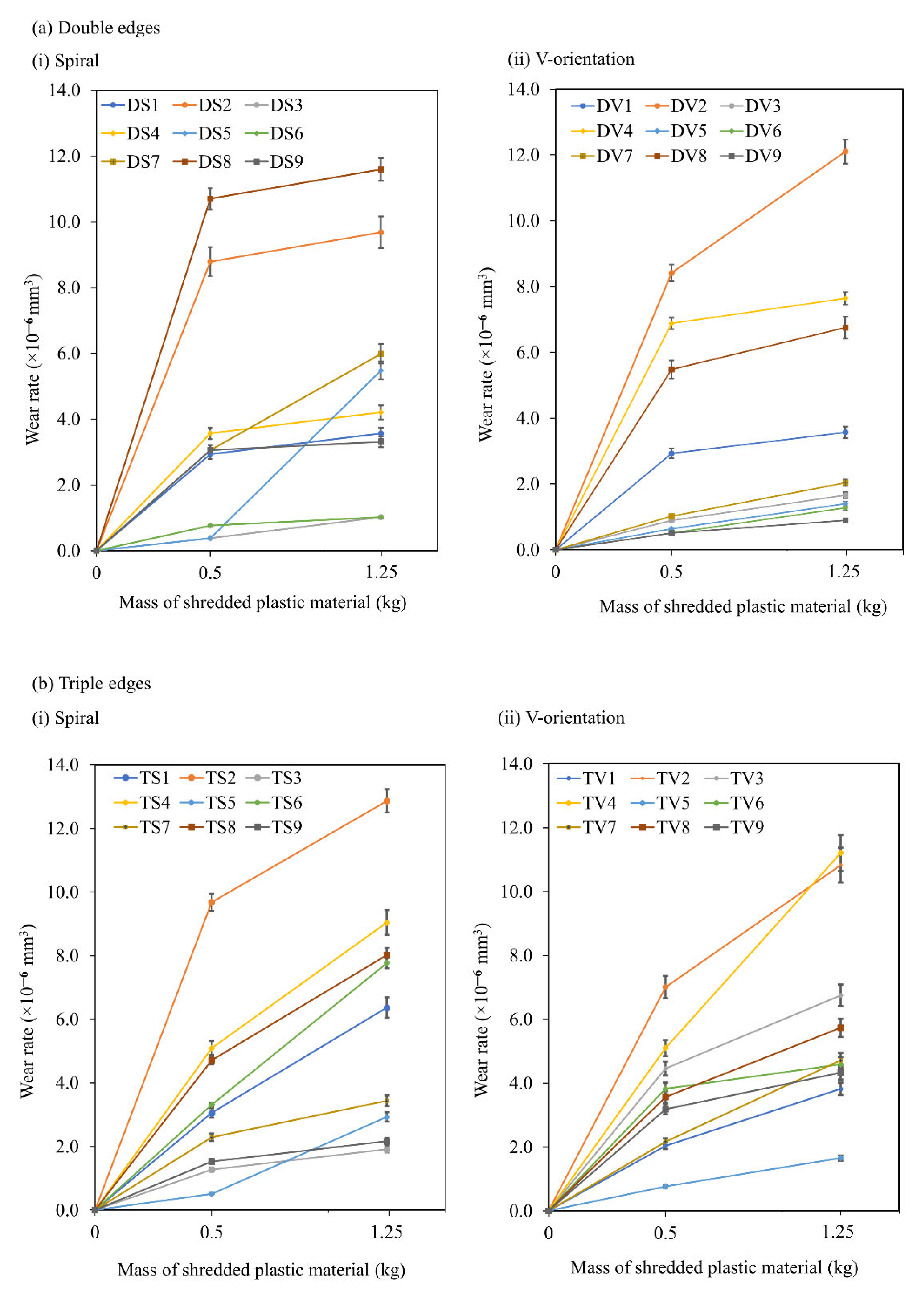
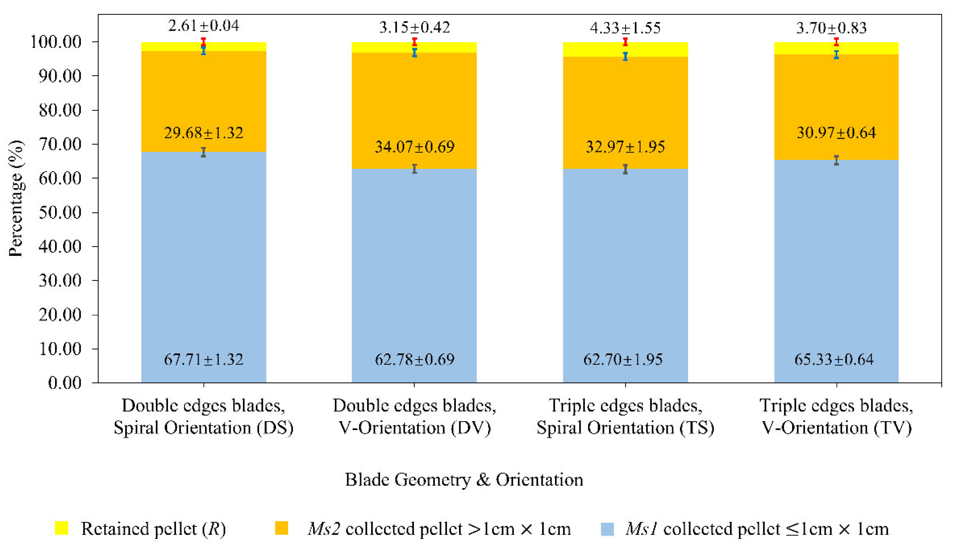
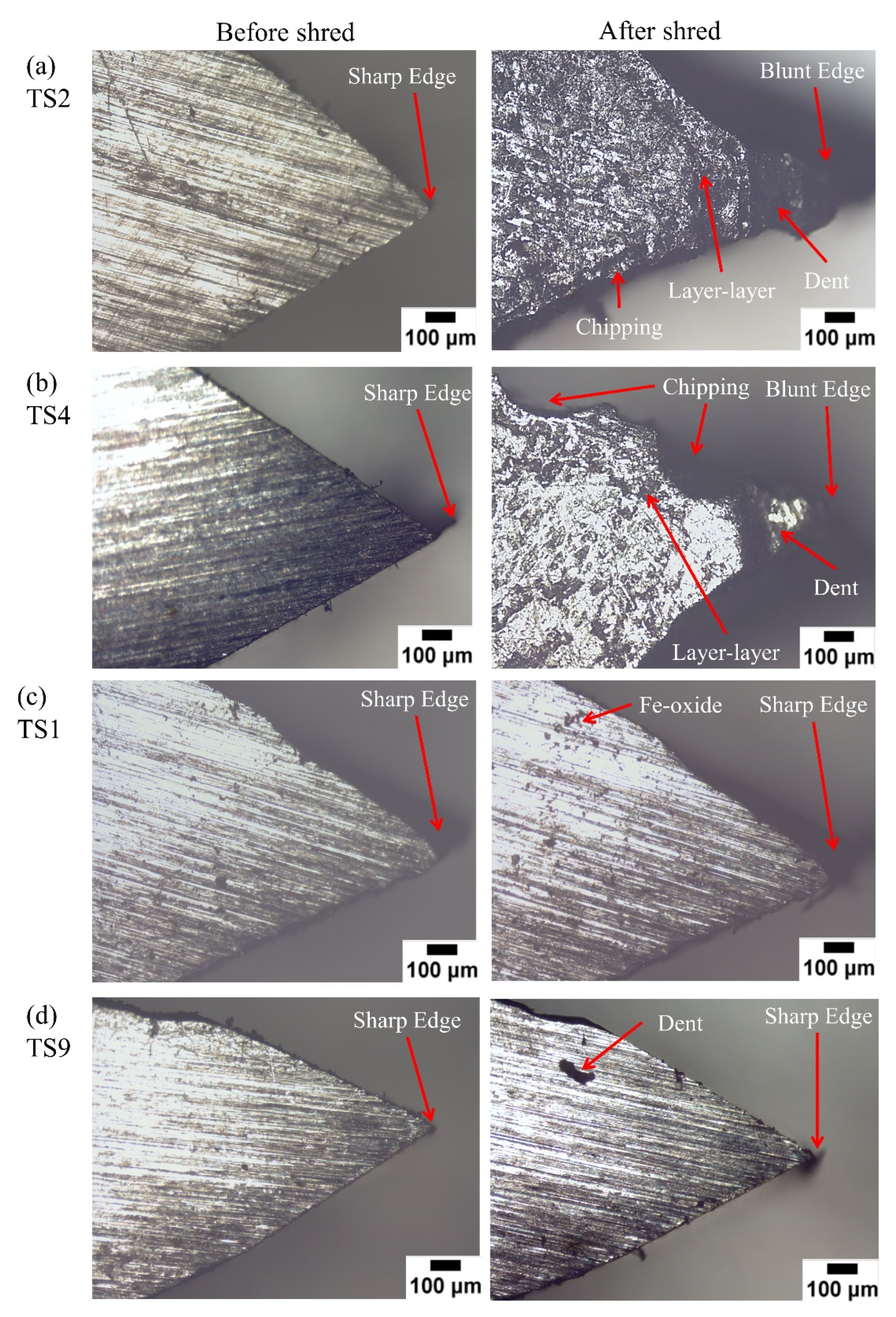
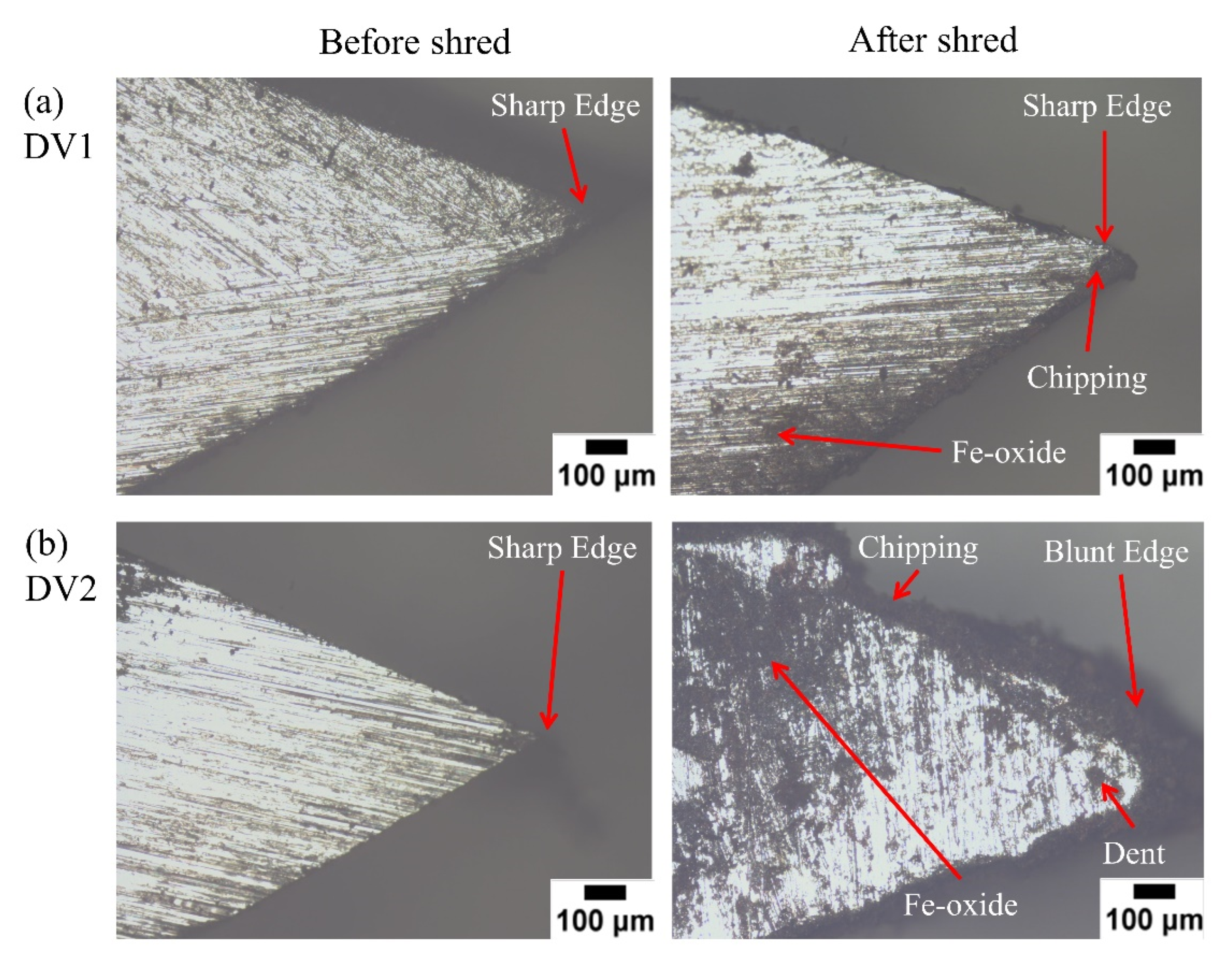
3.1. Blade Wear Rate

Figure 8 shows the wear rate of the blade’s materials after shredding 0.50 kg and 1.25 kg of waste PET plastic materials. The wear rate of the blades might be due to the removal of the oxide layer and material associated with the crack formation on the cutting edge during the shredding process [39]. The loading concentration of the rotating blades during the shredding process was observed based on the blades’ wear rate after the 1.25 kg PET plastic shredding process. The greater wear rate of the blade’s material indicates a higher shredding workload during the process, leading to severe wear on the cutting edge of the shredder blades. The geometry and orientation of the shredder blades with a fewer number of blades recorded a severe wear rate indicating a longer life span and providing a greater cyclical shredding process.
The wear rate of the double edge and triple edge blades are shown in Figure 8a and Figure 8b, respectively. In general, each blade might experience chipping that causes a reduction in its mass. The wear rate for each blade is dependent on the position of the blade inside the shredder machine and the shape or geometry of the blade.
According to Figure 8, the increase in the wear rate of the shredder blades was in accordance with the increase in the mass of the shredded PET plastic. In all blade geometries and orientations, the second and fourth blades consistently experienced the highest wear rate, except for the double edge blade in the spiral orientation, where the highest wear rate was recorded at the eighth and second blades. This indicates the loading was concentrated at the front end of the shredder blades in DV, TS and TV, whilst the workpieces in DS diverged to both ends of the shredder blades during the shredding process. In addition, a small deviation of wear rate was observed on each blade after three repetitions of the shredding process. This indicates the marginal friction due to the contact between the fixed blades and the cutting edge of the shredder blades only led to a minimal influence on the wear rate of the cutting edge during the shredding process.
When double-edge blades were arranged in spiral orientation, the eighth (DS8) blade experienced the highest material wear rate, followed by the second (DS2) blade. The blade in the middle, which is the sixth (DS6) blade, experienced the least mass reduction, as shown in Figure 8a(i). During the shredding process, the workpieces were directly crumbled and shifted to both ends, causing a higher impact at DS2 and DS8. These leads to severe wear rate of DS2 and DS8 due to the higher shredding workload. The experiment was repeated three times, and similar results were obtained where DS2 and DS8 exhibited the highest wear. Optical microscope images in Figure 9 show the sign of wear on the eighth (DS8) and second (DS2) blades after it was used to shred 1.25 kg of PET plastic material. Chipping occurred when there was a removal of material on the shredder blades due to the shredding process [40].
It is visible that the wear on DS8 (Figure 9a) and DS2 (Figure 9b) is relatively severe. The sharp edge of the blade has become blunt, indicating the high-stress distribution and reaction force from the workpieces to the sharp blades during the shredding process [28]. Examination under an optical microscope shows visible chipping, scratches, and dent on the surfaces of both blades. A dent is a small hollow mark on the surface of the material [41,42]. The denting may occur as the workpiece accumulates and jammed at the curve edge resulting in higher dents in the region. On the other hand, the optical microscope image of the sixth (DS6) blade (Figure 9c) remains sharp, with some scratches and debris visible on the edge of the blade. Wear debris is formed due to the abrasion and adhesion induced by the shredding process [43,44]. During the initial stage of the shredding, an asperity is striped and becomes a debris particle when the asperity is not strong enough, and the debris usually is tiny [23]. The debris is not visible at DS8 and DS2, which is due to severe wear during the shredding process.
Different results were obtained when the triple-edge blades in spiral orientation were used to shred PET plastic material (Figure 10). The interval blades: second (TS2), fourth (TS4), sixth (TS6) and eighth (TS8), exhibit higher blade wear rate, with TS2 displaying the highest mass reduction as shown in Figure 8b(i). In contrast, less mass reduction was observed in the first (TS1), third (TS3), seventh (TS7), and ninth (TS9) blades, increasing the number of edges of the shredder blade from the double-edge to triple edges and the contact point between the shredding edge with the workpieces. This might reduce the possibility of the workpieces shifting away from the front end of the shredder blades and immediately shredded by the middle blades (TS6) and back-end blades (TS8).
Optical microscope images (Figure 10a,b) confirmed the TS2 and TS4 blades’ wear-offs were more visible, where the sharp edge became blunt. Chipping, scratches, and dent are also visible. On the other hand, TS1 and TS9 edges remain sharp, as shown in Figure 10c,d.
Changing the orientation of the double-edge and triple-edge blades on the shredding machine shifts the loading concentration of PET plastic waste material. As the double-edge blades were arranged in V-orientation, the blade wear rate is high for the second (DV2), fourth (DV4) and eighth (DV8) blades, with DV2 experiencing the highest wear rate, as shown in Figure 8a(ii). While DV1, DV3, DV5, DV6, DV7, and DV9 blades experienced minimal wear rates. Optical microscope images shown in Figure 11 confirmed that DV2 has prominent damage compared to DV1. Changing from spiral to V-orientation in double-edge blades caused the second, fourth, and eighth blades to experience high loading. Nevertheless, an insignificant wear rate was observed on the remaining six blades.
When triple edge blades are arranged in V-orientation, the mass reduction for TV6 and TV8 blades is lower as compared to the spiral arrangement. With the triple edges V-orientation shredder blade, the loading was concentrated at the front end of the shaft, causing TV2, TV3, and TV4 to experience a higher wear rate. Subsequent characterisations will further support the findings associated with the blade wear rate.
Microstructure and elemental composition characterisation of the shredder blades were performed by scanning electron microscope (SEM) and energy dispersive X-ray (EDX), respectively, for the as-received (P), DS4, DV4, TS4, and TV4, as presented in Figure 12. The SEM images revealed the presence of Fe-oxide accumulated debris and a non-continuous tribo-oxide layer on these regions of shredder blades, suggesting oxidation wear. The EDX elemental microanalysis region was focused on the darker region and crack or dent area of the worn cutting edge after the shredding process, as the oxidation rate is higher in the presence of the crack and dent region [45]. The dark region implies the oxygen-rich area, indicating where the Fe-oxide accumulated.
According to the EDX analysis shown in Figure 12, the as-received cutting edges originally had an oxygen element with 18.12 wt.%. After the shredding process, the EDX analysis revealed a higher weight percentage of oxygen (ranging from 20 wt.% to 30 wt.%) which proved the occurrences of the tribo-oxidation at the crack or dent area during the shredding process. The elemental composition for DS4 changed drastically (Figure 12b) when it was less worn (Figure 8a(i)) because the EDX elemental analysis focused on the layer of cracks or dents for DS4 to confirm the occurrences of oxidation wear. In this case, the increase in oxygen element on the cracks and dent layer in DS4, DV4, TS4 and TV4 indicate the oxidation wear of the shredder blades. The thickness of the oxide layer increases gradually with time and might reduce the hardness of the blade’s surface, causing a high possibility of abrasive and adhesive wear progression [46,47]. This would probably increase the risk of chipping through the cracks or dents. Progressive wear, which was relative to abrasive wear, adhesive wear, and tribo-oxidation, was observed in the wear mechanisms of the shredder blades. Abrasive wear is a wear mechanism that results in material loss from a surface because of hard particles [48,49]. Whilst adhesive wear is a phenomenon that occurs due to a material transfer and subsequent shearing off during adhesive contacts [50,51]. The tribo-oxidation was due to the formation of Fe-oxide on the surface of the shredder blades after the shredding process, as shown in Figure 12.
The abrasive and adhesive wear was identified through the wear rate of each blade (Figure 8) and the optical microstructure image (Figure 9, Figure 10 and Figure 11). The formation of dents, cracks, debris, and scratches was due to the abrasive and adhesive wear induced by the shredding process [43,44]. Chipping occurred as severe damage (broken away) at the tip and nearby surfaces due to the dent, scratches, or cracks. During the shredding process, the stress might concentrate at the cutting edge, which causes chipping to occur and leads to a higher wear rate of the blade’s material. Similar research was performed by Abbasi et al. [23] suggested that the wear mechanism of shredder blades was progressive wear due to abrasive, adhesive and oxidation wear [23]. The wear (dent, scratches, debris) is not only visible at the tip of the blades but also observed on the surface of the blades located nearby the blade’s tip. This indicates the abrasive and adhesive wear owing to the sliding or rubbing of debris or workpieces during the shredding process between the contact surface caused the formation of dents or scratches on the surfaces of the shredder blades.
In short, abrasive wear as a major progressive wear mechanism has been confirmed based on the shredding mechanism, and the microstructure analysis on the blades was used in PET plastic shredding. Based on the blade wear rate implications, the double-edge blade in spiral orientation would have a longer life span, providing a greater cyclical shredding process due to less number of blades recorded severe wear rate as compared to other blades’ geometries and orientations.

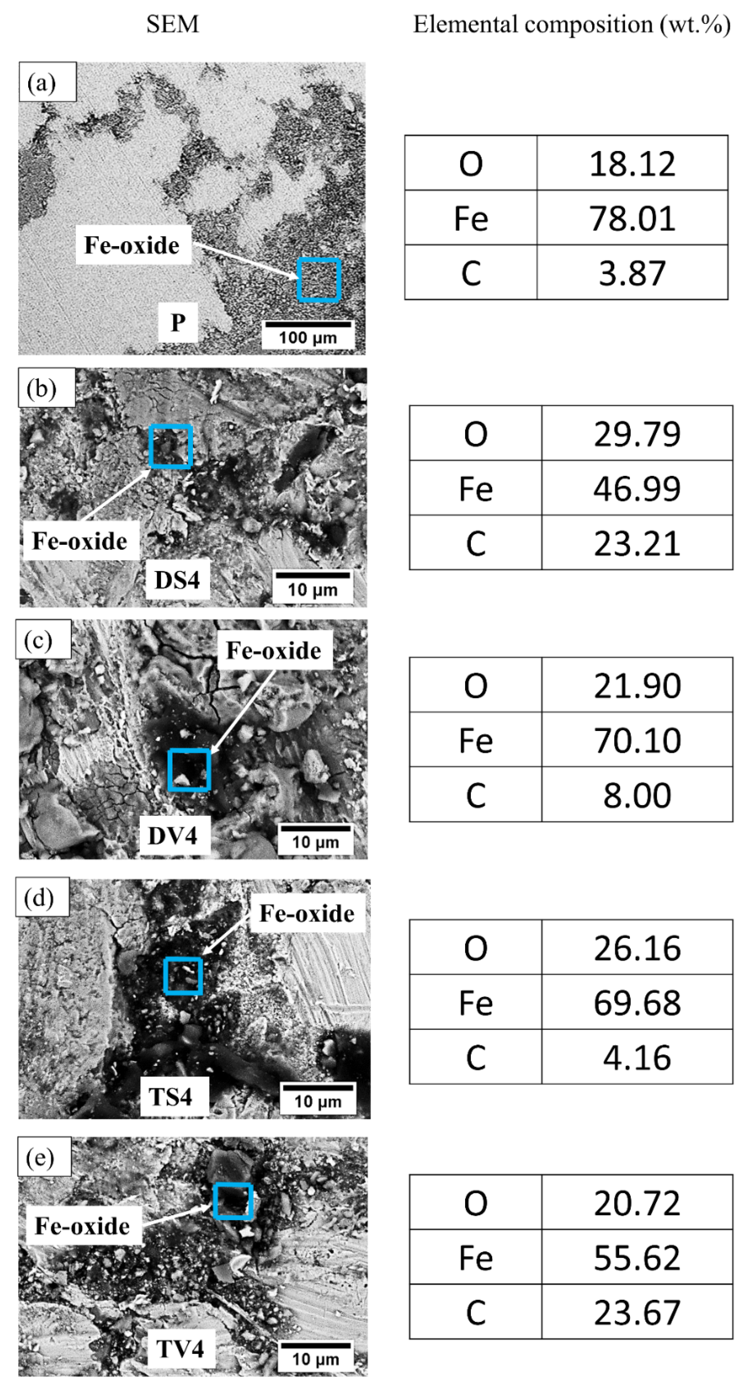
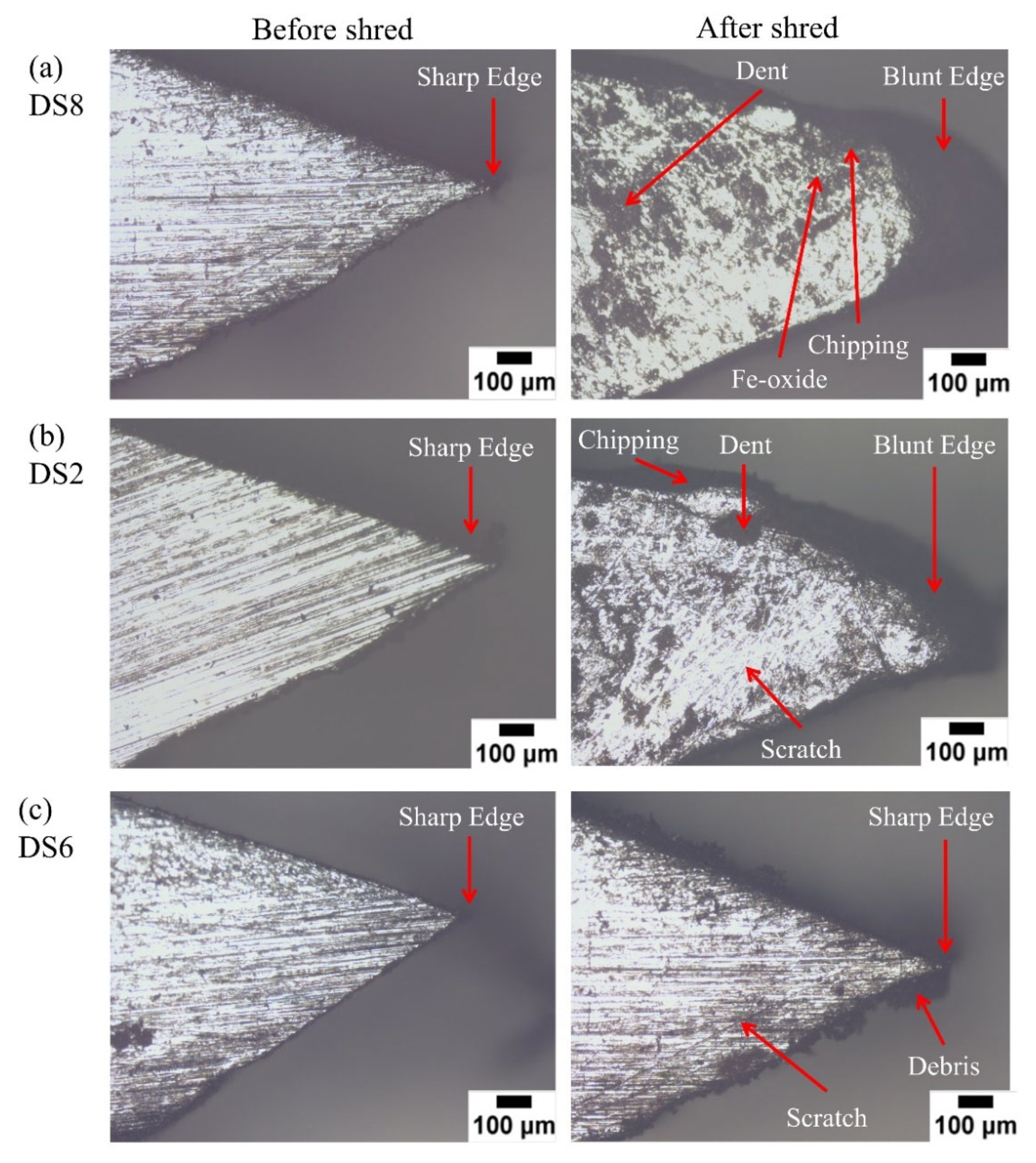
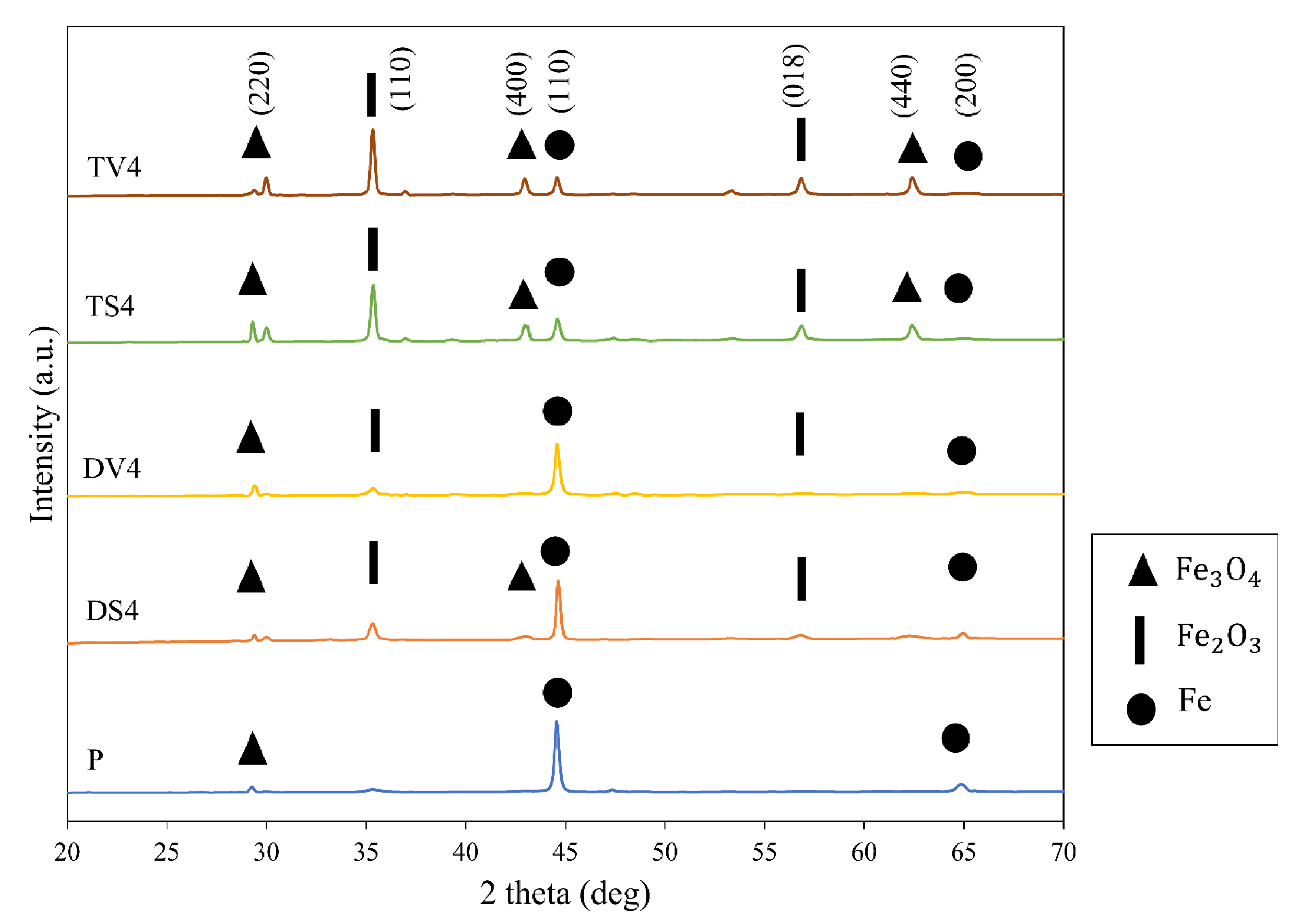
3.2. XRD Analysis on Worn Cutting Edge of Blades

Figure 13 shows the XRD spectra, showing peaks corresponding to ferrite (Fe) (JCPDS 65-4899) [52], magnetite (Fe3O4) (JCPDS 65-3107) [53], and hematite (Fe2O3) (JCPDS 33-0664) [54] in the as-received (P) and worn cutting edges of blades. The as-received blades revealed the presence of low-intensity of magnetite ( Fe 3 O 4 ) and ferrite (Fe), whilst the element of ferrite (Fe), magnetite ( Fe 3 O 4 ), and hematite ( Fe 2 O 3 ) compounds were discovered on the worn cutting edge [23,55]. This is in accordance with the SEM-EDX microanalysis where the oxygen element (18.12 wt.%) was found at the as-received shredder blades. After the shredding process, both EDX and XRD analysis revealed the increase in oxygen element, and the presence of Fe-oxide peak at 35.63° and 57.42°, respectively, proved the occurrence of tribo-oxidation. The slight peak shift from 29.4° to 29.8° for DV4 was primarily attributed to the residual stresses at the worn surfaces from the topmost surface [23]. Nevertheless, the peak splitting (29.4°, 30.0°) for TV4, (29.3°, 30.0°) TS4 and (29.3°, 29.4°) DS4 indicate the distortions of   Fe 3 O 4 crystal lattice [56,57,58]. Lattice distortion might be due to chemical substitution or mechanical dilation/contraction during the shredding process [59].
According to Cui et al. [60], oxidation wear occurred during the dry sliding of ferroalloy resulting in the formation of three basic iron oxides (Fe2O3, Fe3O4, and FeO) [60]. Oxidation wear is featured with the presence of Fe-oxide debris/layer on the worn surfaces. Fe-oxide layer on the worn surfaces was discovered in SEM–EDX analysis of the shredder blades (Figure 12) which suggested the possible rise in the frictional temperature during the shredding process.
XRD analysis revealed a different amount of ferrite and ferrite oxide (magnetite and hematite) on the topmost surface of the worn cutting edges in the double-edge and triple-edge blades. The presence of Fe-oxide indicates the oxidation wear of the shredder blades. Oxidation of ferrite during the shredding process leads to the reduction of the intensity of the ferrite peak at 44.54° and 64.82° in both blade geometry and orientation as compared to P (Figure 13).
Higher peak of Fe 2 O 3 at 35.63° and 57.42° in the triple-edge blades compared to the double-edge blades were mainly due to the geometry of the blades. The presence of Fe 3 O 4 at 44.56° and 62.39° in triple-edge blades indicates a high oxidation rate as compared to double-edge blades. The oxide was formed because of the mutual interaction between the rotating and fixed blade surfaces. At the stable stage of the shredding process, the triple-edge blades have a higher contact rate with the fixed blades as compared to the double-edge blade at a fixed rotational speed. Asperity contacts increased the interfacial temperature due to the frictional heat, leading to the oxide layer formation on the worn surface where a high temperature combined with ambient humidity [23,61]. The asperities were smeared, and debris was developed at the initial stage of wear by abrasion or adhesive spalling of mating surface asperities [23]. An abrasion owing to sliding or rubbing the trapped debris or detached wear particles (e.g., hard oxides) between the contact surfaces, on the other hand, scratched on the worn surfaces [62].
Researchers have reported that frictional heat dissipated due to the asperity contact could rise to over 700 °C [23,63]. Hence, thermal softening could probably occur due to frictional temperature rises at the shredder blades’ surface, which could encourage local deformations during wear.

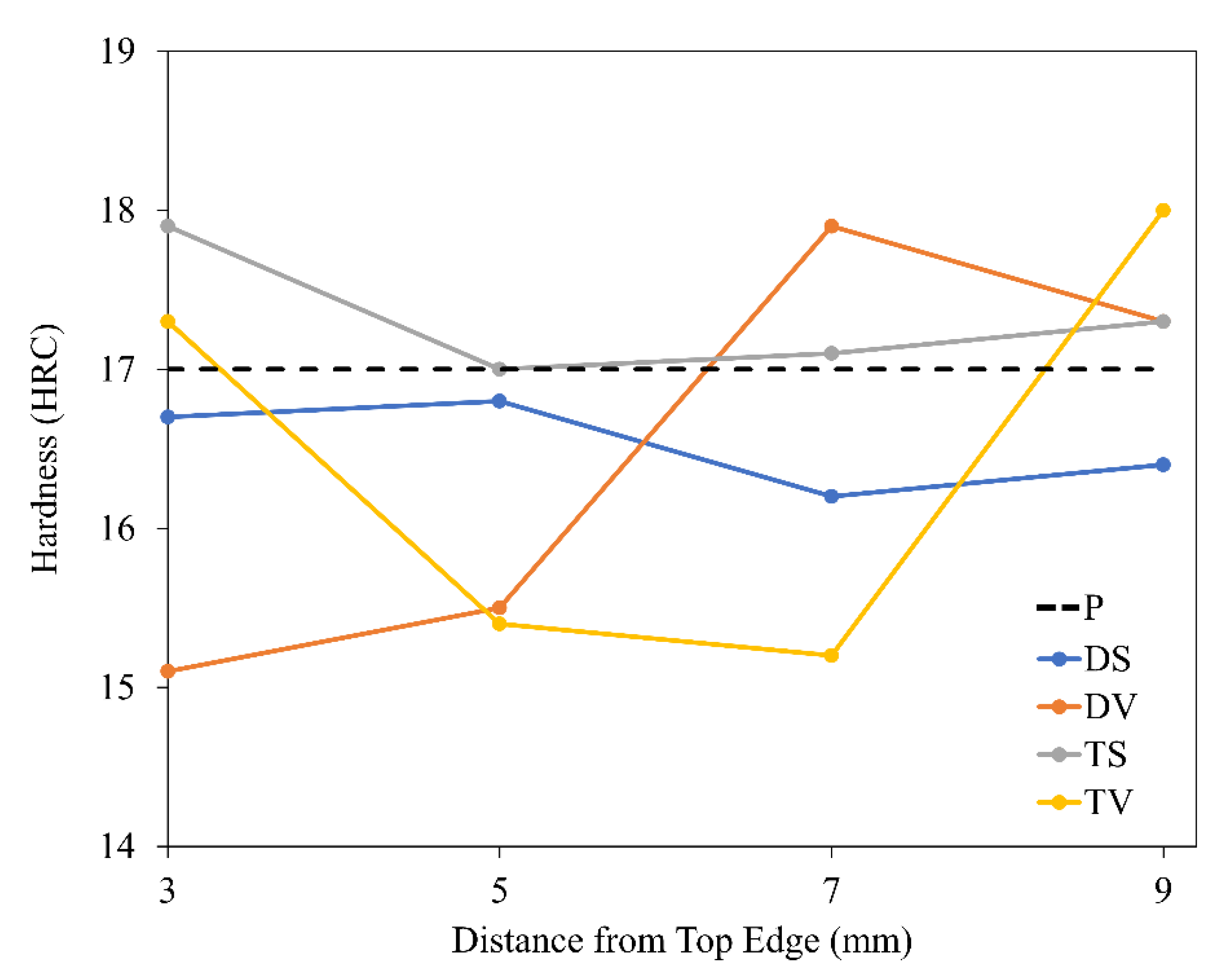
3.3. Hardness of Blades

Generally, the frictional heat due to the asperity contact would reduce the hardness of the worn surface [64]. Thus, thermal softening could take place at the surface close to the worn surface when hardness was greatly reduced. A significant decrease in the hardness indicates the substrate is unable to maintain the original strength.
Figure 14 depicts the hardness profile on the worn cutting edges in double-edge and triple-edge blades with different orientations. Evaluation of the property of the mild steel after the shredding process was obtained from the hardness distribution on the surface of the worn cutting edge. The hardness of the shredder blades after the shredding process is between 15 HRC and 18 HRC, compared to the as-received blade with a hardness of approximately17 HRC. The hardness profile achieved a comparatively stabilised range of values along the worn cutting edges. Additionally, no significant changes were observed in the hardness of fixed blades after the shredding process, too, ranging from 16 HRC to 19 HRC.
After the shredding process, no significant changes were viewed on the hardness profile at the worn cutting surface and fixed blade surface compared to the as-received blade (P). This indicates the heat dissipated due to frictional force between the fixed and rotating blades during the shredding process has minimal influence on the surface hardness of the blades. Therefore, the frictional heat generated during the shredding process was below the critical temperature, which could trigger a drastic change in the hardness of the mild steel [65].

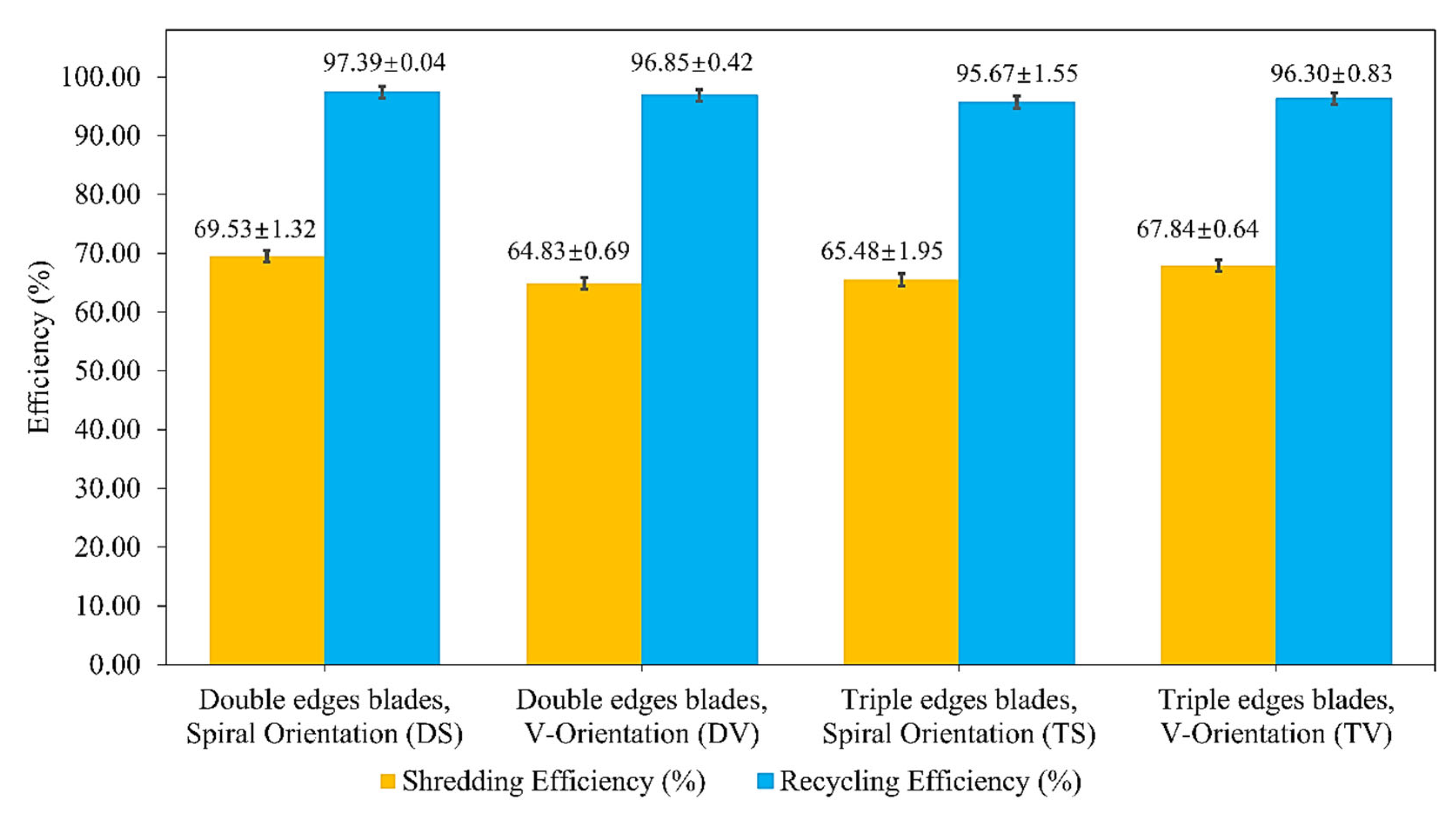
3.4. Evaluation of Performance

The shredded PET plastic was found in irregular shape and size after the shredding process. The shape of the PET plastic tends to be in long strands, as shown in Figure 15a. This possibility was due to the cross-shredding between the shredder blades led to the shredded PET plastic being in long strands in shape [25].
The large size range of the shredded PET grain made it incompatible for re-melting in subsequent machines for the further recycling process. Hence, a mesh/screen with a size of 1 cm × 1 cm was utilised to separate the desired shredded PET plastic grain. The PET plastic grain using the screen is shown in Figure 15b. For each experiment, an initial mass, I, of 1.25 kg was fed into the machine, and the output mass of the shredded PET plastic, Q , was measured, where it was later sieved with a 1 cm × 1 cm screen. The mass of the shredded PET plastic grain with sizes smaller or equal to 1 cm × 1 cm, Ms1 and the mass larger than 1 cm × 1 cm, Ms2, were measured. The experiment was performed in three replicates, and the results were analysed for an average of ten minutes for each experiment. The mass of the retained PET plastic, R , in the shredding chamber is calculated as the difference between the mass input, I, and machine output, Q .
Figure 16 shows the mass percentage of the retained pellet (R) and pellets with sizes less or equal to 1 cm × 1 cm (Ms1) and bigger than 1 cm × 1 cm (Ms2) that were obtained from shredding using: (i) DS; (ii) DV; (iii) TS and (iv) TV.
The output of the collected pellet with the desired grain size at 1 cm × 1 cm was in the range of 62.70 ± 1.95% for TS to 67.71 ± 1.32% for DS. Slightly higher retention was observed at triple-edge blades in spiral orientation; this is attributed to the clogging of the shredding, while retention of 2.61 ± 0.04% was recorded in double-edge blades in spiral orientation. The results showed that retention occurred in all variations of shredder blades. This further indicated that partially the shredded PET crumbled and stuck between the fixed blades and the shredder blades, which definitely impacted the cutting edge of the shredder blades. The increase in the number of cutting edges would marginally increase the retention as this will lead to a higher risk of winding PET plastic during the shredding process [12,13,14].
The shredding efficiency is the shredding machine’s functionality to produce shredded PET plastic grain of 1 cm2 area. According to Figure 17, the shredding efficiency ranged between 64.83 ± 0.69% at DV and 69.53 ± 1.32% at DS, and the machine is highly efficient in the recycling of PET plastic as the recycling efficiency was found at approximately above 95% in all blades’ geometries and orientations.
Comparable research was performed by Oyebade et al. [25] with a sample feeding size of 1.2 kg using a 12 cutting edges single blade in a small-scale shredder machine. The authors found that at different feeding rates and rotational speeds (273.8 rpm), the shredder machine recorded an average shredding efficiency of 60.01%, recycling efficiency at 93.73% and highest retention at 17.90%. A greater number of cutting edges leads to higher retention, which is in accordance with the findings of several previous studies [12,13,14]. In this study, the application of a lower rotational speed significantly improves the shredding and recycling efficiency to 69.53 ± 1.32% and 97.39 ± 0.04%, respectively, as compared to Oyebade et al. [25], even though the setting was slightly different. Higher rotational speed could prevent the grabbing of PET plastic from the shredder blades, which caused a rise in the risk of skipping the PET plastic.
The shifting from double-edge shredder blades to triple-edge shredder blades in the same orientation marginally increases the risk of skipping and winding in PET plastic, causing a trivial reduction in recycling efficiency [12,13,14]. However, the shredding efficiency is correlated to the wear of blades in different geometries and orientations. Severe wear on the shredder blades leads to a slightly lower shredding efficiency. Shredding efficiency of both DV and TS was recorded in the range of 65%, which is slightly lower than DS (69.53 ± 1.32%) and TV (67.84 ± 0.64%). A greater number of blades recorded severe wear rate in triple-edge blades in spiral orientation (e.g., TS2, TS4, TS6, and TS8) and double-edge blades in V-orientation (e.g., DV2, DV4 and DV8), implying marginally lower shredding efficiency. The severe wear of the blade led to the increased gap width between the shredder and fixed blade t g a p , which will slightly deteriorate the shredding process [66].
In short, a similar range of shredding and recycling efficiency was observed for all the blades’ geometries and orientations. However, marginal wear was observed in double-edge shredder blades with spiral orientation since a fewer number of blades recorded a severe wear rate, indicating a longer life span and providing a greater cyclical shredding process.

4. Conclusions

In conclusion, the workpieces were concentrated at the front end of the shredder blades in DV, TS and TV, whilst the workpieces in DS diverged to both ends of the shredder blades during the shredding process. The concentration of workpieces at the front end in DV, TS and TV led to higher wear rates in DV2, TS2 and TV2, whereas blades in the middle and back end had marginal wear. The diversion of workpieces to both ends in DS led to severe wear occurring in DS2 and DS8, where blades in the middle (DS4, DS5, DS6) had minimal wear. The wear mechanism observed on the shredder blade in different geometries and orientations was mainly categorised by progressive wear, which was the abrasive, adhesive, and oxidation wear. Abrasive wear as a major progressive wear mechanism has been confirmed based on the shredding mechanism and the microstructure analysis on the blades. An increase in the oxygen element in EDX and the presence of magnetite and hematite in XRD analysis at the cracks and dents proved that oxidation wear occurred on the blade’s surface. The frictional heat generated during the shredding process was below the critical temperature and therefore had a minimal influence on the blade’s surface hardness. The optimum combination of the blade’s geometry and orientation is the double-edge blade with spiral orientation, which exhibited recycling efficiency at 97.39 ± 0.04%, shredding efficiency at 69.53 ± 1.32%, and retention at 2.61 ± 0.04%, along with less number of blades recorded severe wear indicating longer life span with greater cyclical shredding process.

Author Contributions

Conceptualization, J.H.W., G.J.H.M. and N.J.S.; methodology, J.H.W., G.J.H.M. and N.J.S.; validation, W.M.J.K., B.L.C., G.J.H.M. and N.J.S.; formal analysis, J.H.W.; investigation, J.H.W.; resources, S.A.B., B.L.C., G.J.H.M. and N.J.S.; data curation, J.H.W., G.J.H.M. and N.J.S.; writing—original draft preparation, J.H.W.; writing—review and editing, W.M.J.K., S.A.B., B.L.C., G.J.H.M. and N.J.S.; visualization, J.H.W., G.J.H.M. and N.J.S.; supervision, G.J.H.M. and N.J.S.; project administration, G.J.H.M. and N.J.S.; funding acquisition, G.J.H.M. and N.J.S. All authors have read and agreed to the published version of the manuscript.

Funding

This work was supported by the Ministry of Higher Education, Malaysia (FRGS/1/2020/TK0/UMS/02/17).

Institutional Review Board Statement

Not applicable.

Informed Consent Statement

Not applicable.

Data Availability Statement

Not applicable.

Conflicts of Interest

The authors declare no conflict of interest.

References

  1. Okiy, S.; Emagbetere, E.; Oreko, B.U.; Okwu, M. Design and Fabrication of Polythene Pelletizing Machine for Urban Communities in Nigeria. Am. J. Eng. Res. 2018, 7, 32–41. [Google Scholar]
  2. Andrady, A.L.; Neal, M.A. Applications and Societal Benefits of Plastics. Philos. Trans. R. Soc. B Biol. Sci. 2009, 364, 1977–1984. [Google Scholar]
  3. Cheng, C.S.; Lin, K.W.; Qing, T.Y. Effect of Outsole Thickness on Running Biomechanics. Malays. J. Sci. 2022, 41, 23–34. [Google Scholar] [CrossRef]
  4. Thompson, R.C.; Moore, C.J.; Vom Saal, F.S.; Swan, S.H. Plastics, The Environment and Human Health: Current Consensus and Future Trends. Philos. Trans. R. Soc. B Biol. Sci. 2009, 364, 2153–2166. [Google Scholar]
  5. Ayo, A.W.; Olukunle, O.; Adelabu, D. Development of a Waste Plastic Shredding Machine. Int. J. Waste Resour. 2017, 7, 1–4. [Google Scholar]
  6. Santander, P.; Sanchez, F.A.C.; Boudaoud, H.; Camargo, M. Closed Loop Supply Chain Network for Local And Distributed Plastic Recycling For 3D Printing: A MILP-based optimization approach. Resour. Conserv. Recycl. 2020, 154, 104531. [Google Scholar] [CrossRef]
  7. Jadhav, N.; Patil, A.; Lokhande, H.; Turambe, D. Development of Plastic Bottle Shredding Machine. Int J. Waste Resour. 2018, 8, 2. [Google Scholar] [CrossRef]
  8. D’Ambrières, W. Plastics Recycling Worldwide: Current Overview and Desirable Changes. Field Actions Sci. Rep. J. Field Actions 2019, 19, 12–21. [Google Scholar]
  9. Kreiger, M.A.; Mulder, M.; Glover, A.G.; Pearce, J.M. Life Cycle Analysis of Distributed Recycling of Post-Consumer High Density Polyethylene For 3-D Printing Filament. J. Clean. Prod. 2014, 70, 90–96. [Google Scholar]
  10. Wong, J.; Gan, M.; Chua, B.; Gakim, M.; Siambun, N. Shredder Machine for Plastic Recycling: A Review Paper. In IOP Conference Series: Materials Science and Engineering; IOP Publishing: Bristol, UK, 2022; p. 012007. [Google Scholar]
  11. Pedraza-Yepes, C.; Pelegrina-Romero, M.A.; Pertuz-Martinez, G.J. Analysis by Means of the Finite Element Method of the Blades of a PET Shredder Machine with Variation of Material and Geometry. Contemp. Eng. Sci. 2018, 11, 4113–4120. [Google Scholar]
  12. Rathnam, A.V.; Babu, U.H. Optimal Design and Analysis of Twin Shaft Shredder. Int. J. Res. Innov. 2017, 4, 805–813. [Google Scholar]
  13. Ekman, R. Development of a Plastic Shredder; LUND University: Lund, Sweden, 2018. [Google Scholar]
  14. Ravi, S. (Ed.) Utilization of Upgraded Shredder Blade and Recycling the Waste Plastic and Rubber Tyre. In International Conference on Industrial Engineering and Operations Management; IEOM Society International: Paris, France, 2018. [Google Scholar]
  15. VijayAnanth, S.; Sureshkumar, T.; Dhanasekaran, C.; Kumar, A. Design and Fabrication of Plastic Shredder Machine for Clean Environment. Int. J. Manag. Technol. Eng. 2018, 8, 4601–4606. [Google Scholar]
  16. Dattatraya, R.P.; Bhalgat, S.M. Cutter Blade Design for Shredder Machine. Int. J. Sci. Res. Publ. 2020, 10, 1022–1027. [Google Scholar] [CrossRef]
  17. Siddiqui, F.; Patil, H.; Raut, S.; Wadake, O.; Tandel, S. Design and Fabrication of Paper Shredder Machine. Int. Res. J. Eng. Technol. (IRJET) 2017, 4, 770–775. [Google Scholar]
  18. Kumaran, P.; Lakshminarayanan, N.; Martin, A.V.; George, R.; JoJo, J. Design and Analysis Of Shredder Machine for e-Waste Recycling using CATIA. In IOP Conference Series: Materials Science and Engineering; IOP Publishing: Bristol, UK, 2020; p. 012013. [Google Scholar]
  19. Hakkens, D. Forum: Shredder Design Has Major Flaw. 2020. Available online: https://davehakkens.nl/community/forums/topic/shredder-design-has-major-flaw/ (accessed on 22 June 2022).
  20. Neugebauer, R.; Bouzakis, K.-D.; Denkena, B.; Klocke, F.; Sterzing, A.; Tekkaya, A.; Wertheim, R. Velocity Effects in Metal Forming and Machining Processes. CIRP Ann. 2011, 60, 627–650. [Google Scholar] [CrossRef]
  21. Ezugwu, E.; Bonney, J.; Yamane, Y. An Overview of The Machinability of Aeroengine Alloys. J. Mater. Processing Technol. 2003, 134, 233–253. [Google Scholar] [CrossRef]
  22. Tao, Y.; Bai, Y.; Wu, Y. Influence of Blade Thickness on Solid–Liquid Two-Phase Flow and Impeller Wear in a Ceramic Centrifugal Slurry Pump. Processes 2021, 9, 1259. [Google Scholar] [CrossRef]
  23. Abbasi, E.; Luo, Q.; Owens, D. Case study: Wear mechanisms of NiCrVMo-steel and CrB-steel scrap shear blades. Wear 2018, 398, 29–40. [Google Scholar] [CrossRef]
  24. Tomita, Y. Development of Fracture Toughness Of Ultrahigh Strength, Medium Carbon, Low Alloy Steels for Aerospace Applications. Int. Mater. Rev. 2000, 45, 27–37. [Google Scholar] [CrossRef]
  25. Oyebade, D.; Okunola, O.; Olanrewaju, O. Development of Shredding and Washing Machine for Polyethylene Terephthalate (PET) Bottles Pelletizer. Int. J. Eng. Sci. Appl. 2019, 3, 102–109. [Google Scholar]
  26. Precious Plastic Universe. Precious Plastic 2020. Available online: https://preciousplastic.com/ (accessed on 30 April 2022).
  27. Suliman, M.S.; Johar, M.A. Development of Shredding Machine for Plastic Recycling. Res. Prog. Mech. Manuf. Eng. 2022, 3, 160–169. [Google Scholar]
  28. Nasr, M.F.; Yehia, K.A. Stress Analysis of a Shredder Blade for Cutting Waste Plastics. J. Int. Society Sci. Eng. 2019, 1, 9–12. [Google Scholar] [CrossRef]
  29. Cardona, D.M.M.; Wongsa-Ngam, J.; Jimenez, H.; Langdon, T.G. Effects on Hardness and Microstructure of AISI 1020 Low-carbon Steel Processed by High-pressure Torsion. J. Mater. Res. Technol. 2017, 6, 355–360. [Google Scholar] [CrossRef]
  30. Salleh, M.; Ishak, M.; Aiman, M.; Zaifuddin, Q.; Quazi, M. (Eds.) The Effect of Laser Surface Hardening on the Surface Hardness Of Mild Steel. In IOP Conference Series: Materials Science and Engineering; IOP Publishing: Bristol, UK, 2020. [Google Scholar]
  31. Khan, M.; Dewan, M.W.; Sarkar, M.Z. Effects of Welding Technique, Filler Metal and Post-Weld Heat Treatment on Stainless Steel and Mild Steel Dissimilar Welding Joint. J. Manuf. Processes 2021, 64, 1307–1321. [Google Scholar] [CrossRef]
  32. Aondona, I.P.; Azoro, K.U. The Development of Ecofriendly Energizers as Replacement for Industrial Chemical Energizers in the Case Hardening of Mild Steel Materials. Int. J. Mech. Civ. Eng. 2019, 2, 14–27. [Google Scholar]
  33. Borisade, S.; Ajibola, O.; Adebayo, A.; Oyetunji, A. Development of Mathematical Models for the Prediction of Mechanical Properties of Low Carbon Steel (LCS). Mater. Today Proc. 2021, 38, 1133–1139. [Google Scholar] [CrossRef]
  34. Callister, W.D. Materials Science and Engineering an Introduction; John Wiley: New York, NY, USA, 2007. [Google Scholar]
  35. Tegegne, A.; Tsegaye, A.; Ambaye, E.; Mebrhatu, R. Development of Dual Shaft Multi Blade Waste Plastic Shredder for Recycling Purpose. Int. J. of Res. and Sci. Innov. (IJRSI) 2019, 6, 49–55. [Google Scholar]
  36. Hopewell, J.; Dvorak, R.; Kosior, E. Plastics Recycling: Challenges and Opportunities. Philos. Trans. R. Soc. B Biol. Sci. 2009, 364, 2115–2126. [Google Scholar] [CrossRef]
  37. Blau, P.J. On the Nature of Running-in. Tribol. Int. 2005, 38, 1007–1012. [Google Scholar] [CrossRef]
  38. Ikechukwu, O. Design of Used PET Bottles Crushing Machine for Small Scale Industrial Applications. Int. J. of Eng. Technol. IJET 2017, 3, 157–168. [Google Scholar]
  39. Maranho, O.; Rodrigues, D.; Boccalini, M., Jr.; Sinatora, A. Mass Loss and Wear Mechanisms of HVOF-Sprayed Multi-Component White Cast Iron Coatings. Wear 2012, 274, 162–167. [Google Scholar] [CrossRef]
  40. Mabrouki, T.; Courbon, C.; Zhang, Y.; Rech, J.; Nélias, D.; Asad, M.; Hamdi, H.; Belhadi, S.; Salvatore, F. Some Insights on the Modelling of Chip Formation and its Morphology During Metal Cutting Operations. Comptes Rendus Mec. 2016, 344, 335–354. [Google Scholar] [CrossRef]
  41. Sheng, J.; Zhou, J.; Huang, S.; Mei, Y.; Mu, D.; Meng, X.; Fan, J. Characterization and Tribological Properties of Micro-Dent Arrays Produced by Laser Peening on ZCuSn10P1 alloy. Int. J. Adv. Manuf. Technol. 2015, 76, 1285–1295. [Google Scholar] [CrossRef]
  42. Nakatsuji, T.; Mori, A. The Tribological Effect of Mechanically Produced Micro-Dents by a Micro Diamond Pyramid on Medium Carbon Steel Surfaces in Rolling-Sliding Contact. Meccanica 2001, 36, 663–674. [Google Scholar] [CrossRef]
  43. Zmitrowicz, A. Wear Debris: A Review of Properties and Constitutive Models. J. Theor. Appl. Mech. 2005, 43, 3–35. [Google Scholar]
  44. Kim, B.; Jiang, J.C.; Aswath, P.B. Mechanism of Wear at Extreme Load and Boundary Conditions with Ashless Anti-Wear Additives: Analysis of Wear Surfaces and Wear Debris. Wear 2011, 270, 181–194. [Google Scholar] [CrossRef]
  45. Wen, J.; Cao, R.; Che, H.; Dong, H.; Zhang, H.; Yan, Y.; Liaw, P.K. The Oxidation Effect on the Cracking Behavior of a Co-Based Alloy under Thermal Shocks. Corros. Sci. 2020, 173, 108828. [Google Scholar] [CrossRef]
  46. Wang, F.; Cui, X.; Yang, Z.; Wei, M.; Wang, S. Oxidation and Tribo-Oxidation of An Alloy Steel H13 at Elevated Temperature. Proc. Inst. Mech. Eng. Part J J. Eng. Tribol. 2009, 223, 881–885. [Google Scholar] [CrossRef]
  47. Mishra, A. Influence of Oxidation on the Wear of Alloys. Int. J. Mech. Eng. Robot. Res. 2014, 3, 583. [Google Scholar]
  48. Lewis, R.; Olofsson, U. Wheel-Rail Interface Handbook; Elsevier: Amsterdam, The Netherlands, 2009. [Google Scholar]
  49. Wei, H.; Wenjian, C.; Shaoping, W.; Tomovic, M.M. Mechanical Wear Debris Feature, Detection, and Diagnosis: A Review. Chin. J. Aeronaut. 2018, 31, 867–882. [Google Scholar]
  50. Dwivedi, D.K. Adhesive Wear Behaviour of Cast Aluminium–Silicon Alloys: Overview. Mater. Des. (1980–2015) 2010, 31, 2517–2531. [Google Scholar] [CrossRef]
  51. Sousa, V.F.; Silva, F.J.; Lopes, H.; Casais, R.C.; Baptista, A.; Pinto, G.; Alexandre, R. Wear Behavior and Machining Performance of TiAlSiN-Coated Tools Obtained by dc MS and HiPIMS: A Comparative Study. Materials 2021, 14, 5122. [Google Scholar] [CrossRef] [PubMed]
  52. Choi, C.H.; Lee, S.Y.; Park, S.H.; Woo, S.I. Highly Active N-Doped-Cnts Grafted on Fe/C Prepared by Pyrolysis Of Dicyandiamide On Fe2O3/C For Electrochemical Oxygen Reduction Reaction. Appl. Catal. B Environ. 2011, 103, 362–368. [Google Scholar] [CrossRef]
  53. Mishra, A.; Sardar, M. Isolation of Genomic DNA by Silane-Modified Iron Oxide Nanoparticles. In Nanotechnology: Novel Perspectives and Prospects; McGraw Hill Education: New York, NY, USA, 2015; pp. 309–315. [Google Scholar]
  54. Sun, Z.; Xiao, C.; Hussain, F.; Zhang, G. Synthesis of Stable And Easily Recycled Ferric Oxides Assisted by Rhodamine B for Efficient Degradation Of Organic Pollutants In Heterogeneous Photo-Fenton System. J. Clean. Prod. 2018, 196, 1501–1507. [Google Scholar] [CrossRef]
  55. Hutchinson, B.; Hagström, J.; Karlsson, O.; Lindell, D.; Tornberg, M.; Lindberg, F.; Thuvander, M. Microstructures and Hardness of As-Quenched Martensites (0.1–0.5% C). Acta Mater. 2011, 59, 5845–5858. [Google Scholar] [CrossRef]
  56. Shishonok, E.; Luhin, V.; Steeds, J. XRD Doping Control of Light-Emitting Cbn with a Large Size Mismatch between the Dopant and Intrinsic Atoms. World J. Eng. Technol. 2016, 4, 174–185. [Google Scholar] [CrossRef]
  57. Darul, J. (Ed.) Thermal Instability of The Tetragonally Distorted Structure of Copper-iron. In Eleventh European Powder Diffraction Conference: Warsaw, 19–22 September 2008; Walter de Gruyter GmbH & Co KG: Berlin, Germany, 2015. [Google Scholar]
  58. Le Bihan, T.; Idiri, M.; Heathman, S. New Investigation of Pressure-Induced Rhombohedral Distortion of Uranium Nitride. J. Alloys Compd. 2003, 358, 120–125. [Google Scholar] [CrossRef]
  59. Zhao, Y.; Lei, Z.; Lu, Z.; Huang, J.; Nieh, T. A Simplified Model Connecting Lattice Distortion with Friction Stress of Nb-Based Equiatomic High-Entropy Alloys. Mater. Res. Lett. 2019, 7, 340–346. [Google Scholar] [CrossRef] [Green Version]
  60. Cui, X.; Wang, S.; Wang, F.; Chen, K. Research on Oxidation Wear Mechanism of The Cast Steels. Wear 2008, 265, 468–476. [Google Scholar] [CrossRef]
  61. Pujilaksono, B.; Jonsson, T.; Halvarsson, M.; Svensson, J.-E.; Johansson, L.-G. Oxidation of Iron at 400–600 C in Dry and Wet O2. Corros. Sci. 2010, 52, 1560–1569. [Google Scholar] [CrossRef]
  62. Gronostajski, Z.; Kaszuba, M.; Hawryluk, M.; Zwierzchowski, M. A Review of the Degradation Mechanisms of the Hot Forging Tools. Arch. Civ. Mech. Eng. 2014, 14, 528–539. [Google Scholar] [CrossRef]
  63. Katsuki, F. Subsurface Characteristics of a Fe–0.4 wt% C Martenstic Steel Abraded with Nanoindentation and Cross-sectional TEM Techniques. Wear 2013, 303, 92–97. [Google Scholar] [CrossRef]
  64. Wei, M.; Chen, K.; Wang, S.; Cui, X. Analysis for Wear Behaviors of Oxidative Wear. Tribol. Lett. 2011, 42, 1–7. [Google Scholar] [CrossRef]
  65. Winkelmann, H.; Badisch, E.; Varga, M.; Danninger, H. Wear Mechanisms at High Temperatures. Part 3: Changes of The Wear Mechanism in The Continuous Impact Abrasion Test with Increasing Testing Temperature. Tribol. Lett. 2010, 37, 419–429. [Google Scholar] [CrossRef]
  66. Shih, A.J.; McCall, R.C. Kinematics and Wear of Tool Blades for Scrap Tire Shredding. Mach. Sci. Technol. 2004, 8, 193–210. [Google Scholar] [CrossRef]
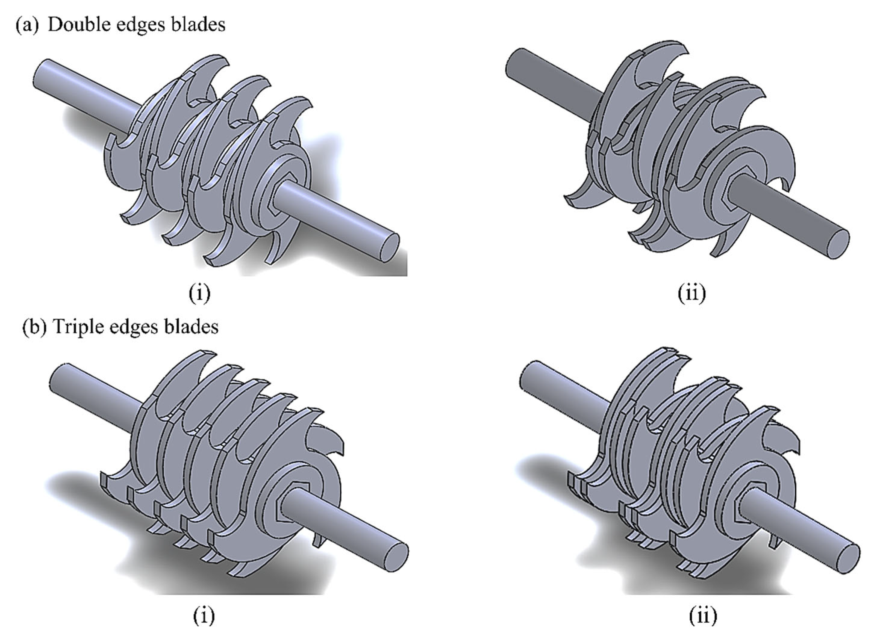
Figure 1. Geometrical design of the (a) double-edge blade and (b) triple-edge blade.
Machines 10 00760 g001
Figure 2. (a) Double-edge, and (b) triple-edge blades in (i) spiral, and (ii) V-orientation.
Machines 10 00760 g002
Figure 3. Single-shaft shredder machine.
Machines 10 00760 g003
Figure 4. The configuration and numbering of the shredder blades in the shredder machine.
Machines 10 00760 g004
Figure 5. (a) Shredding action on the PET plastic by the shredder blades from side view, and (b) the cross section of the two blades and the gap, t g a p .
Machines 10 00760 g005
Figure 6. Definition of the offset angle α . (a) Shredder blade with offset angle, α = 0 and (b) Shredder blade with offset angle, α .
Machines 10 00760 g006
Figure 7. Measurement points of hardness on the worn cutting edge.
Machines 10 00760 g007
Figure 8. Wear rate of (a) double and (b) triple-edge blade’s material after shredding of PET plastic in (i) spiral and (ii) V-orientation.
Machines 10 00760 g008
Figure 9. Optical microscope images of the double-edge blades in spiral orientation, before and after shredding of PET plastic: (a) DS8, (b) DS2, (c) DS6.
Machines 10 00760 g009
Figure 10. Optical microscope images of triple-edge blades arranged in spiral orientation, before and after shredding of PET plastic: (a) TS2, (b) TS4, (c) TS1, (d) TS9.
Machines 10 00760 g010
Figure 11. Optical microscope images of double-edge blades arranged in V-orientation, before and after shredding of the PET plastic: (a) DV1, (b) DV2.
Machines 10 00760 g011
Figure 12. (ae) SEM micrographs and EDX elemental composition corresponding to the worn cutting edge showing the presence of oxygen rich areas.
Machines 10 00760 g012
Figure 13. XRD spectra, showing peak corresponding to ferrite, magnetite, and hematite in the original and worn cutting edges of blades.
Machines 10 00760 g013
Figure 14. Hardness profile on the surface of the worn cutting edges in double-edge and triple edges with spiral and V-orientation shredder blades.
Machines 10 00760 g014
Figure 15. Shredded PET plastic grain with (a) long strands and (b) PET plastic grain after screen/mesh.
Machines 10 00760 g015
Figure 16. Mass percentage of retained pellet (R) and pallets with size >1 cm × 1 cm (Ms2), and ≤1 cm × 1 cm (Ms1) obtained from shredding using DS, DV, TS, and TV blades and orientations.
Machines 10 00760 g016
Figure 17. The percentage of shredding and recycling efficiency obtained from shredding using DS, DV, TS, and TV blades and orientations.
Machines 10 00760 g017
Table 1. Abbreviations of shredder blades in different geometries and orientations.
Abbreviations of Shredder BladesGeometriesOrientations
DSDouble edgesSpiral
DVDouble edgesV-orientation
TSTriple edgesSpiral
TVTriple edgesV-orientation
Publisher’s Note: MDPI stays neutral with regard to jurisdictional claims in published maps and institutional affiliations.

